user adjustable stroke range to 175 inches (3 meters) easy ... · easy push-button zero and span...
TRANSCRIPT

SR1M | 1
tel: 800.423.5483 • +1.818.701.2750 • fax: +1.818.701.279920630 Plummer Street • Chatsworth, CA 91311
celesco.com • [email protected]
SR1MUser Adjustable Stroke Range to 175 inches (3 meters)Easy Push-Button Zero and Span AdjustDesigned for Outdoor & IP67 environmentsIn Stock for Quick Delivery!
Industrial • User Scalable 4–20mA Output
ORDERING INFORMATION
SPECIFICATIONS
Full Stroke Range, SR1M-125 125 inches (3175 mm), maximum
Full Stroke Range, SR1M-175 175 inches (4445 mm), maximum
Minimum Full Stroke Range 1 inches (25 mm)
Output Signal Settings 4...20mA, 20...4mA
Input Voltage 10-30 VDC
Accuracy, full stroke range ≥ 10 inches (254 mm) .5% FS.
Accuracy, full stroke range < 10 inches (254 mm) consult factory
Repeatability .1% FS.
Resolution .0015% FS.
Output Signal Update Rate 1 msec
Maximum Velocity 80 inches (2 meters) per second
Maximum Acceleration 10 g (retraction)
Measuring Cable Tension 23 oz. (6,4 N) ±30%
Sensor plastic-hybrid precision potentiometer
Cycle Life 250,000 (potentiometer)
Enclosure polycarbonate
Measuring Cable .034-inch dia. nylon-coated stainless
Electrical Connection M12 Connector (mating plug included)
Environmental Suitability NEMA 6, IP67
Operating Temperature -40˚ to 185˚ F (-40˚ to 85˚ C)
Weight 2.5 lbs. (1.3 Kg)
6” [152 mm] 4” [100 mm]4.75” [120 m
m]
9036810-0040
13 ft (4 m)22 AWG (.34mm²)
125-inch stroke range,4–20mA output,4-pin M12 mating plug & mounting bracket included.
Order No.
SR1M-125175-inch stroke range,4–20mA output,4-pin M12 mating plug &mounting bracket included.
Order No.
SR1M-175for short-run connections,optional 13-ft cordset with 4-pin M12 matingplug.
Order No.
Output Signal:
4...20mA
(0% fs.) (100% fs.)
The SR1M is part of a series of rugged, low-cost, high perfor-mance string pots built for wet environments and outdoor applications. Designed for the rigors of outdoor construc-tion equipment or the demands of a factory floor, the SR1M is the perfect low-cost solution for OEM and stocking dis-tributors.
What sets this sensor apart from other string pots, is the internal programmable digital circuitry that gives the cus-tomer a one-size-fits-all approach for many applications. The SR1M ships factory calibrated to the full stroke range but the output signal can be easily re-scaled to match any stroke down to 1 inch (25 mm).
175-inch model shown

2 | SR1M
tel: 800.423.5483 • +1.818.701.2750 • fax: +1.818.701.2799
now part of Measurement Specialties, Inc.celesco.com • [email protected]
1.7” [45 mm]
13.6 ft. [4 M]
22 AWG (.34mm2)
contact view
2
3
1
4
Electrical Connection
Cable Exit Direction Options
Changing the Cable Exit
2.4” [60mm]
.25 in [6 mm]max. cable dia.
contact view
2
3
1
4
Measuring Cable
Mounting Bracket
Electrical Connector
Rear Cover
see fig. 1
see fig. 2
see fig. 3
see fig. 4
Changing Measuring Cable ExitTo change the direction of the measuring cable, remove the 4 mounting bracket screws and rotate bracket to one of four available positions. See figures 1 - 4 on the following pages for mounting dimensions.
Changing Electrical Connector DirectionTo change the position of the electrical connector, remove the 4 rear cover screws and carefully sepa-rate rear cover from the sensor body.
Rotate the rear cover to desired position being care-ful to not tangle the wiring harness that runs to the connector.
Factory Calibrated Stroke Range
10...30 vdc 1 brown n/c 2 white output signal 3 blue n/c 4 black
i/o connector colorcode signal pin (cordset)
The full scale output signal is set at the factory to the maximum full stroke range of the sensor. The ZERO point (output = 4mA) is set at the beginning* of the stroke range (0 inches) and the SPAN point (output = 20mA) is set to the end of the range (125 inches or 175 inches depending on model).
*Important — The ZERO point is set at the factory with the measuring cable pulled out .125 inches from full retraction. If the measuring cable becomes fully retracted at any time when the sensor is under power, the output signal will begin to fluctuate. This is normal and fluctuation will stop as soon as the cable is extended greater than .125 inches.
This is for the factory setting only and the ZERO may be repro-grammed at full retraction at any time.
Full Stroke Range
4 mA
20 mA
.125-in (3,2 mm)
Factory Set ZERO
Factory Set SPAN
SR1M | 3
tel: 800.423.5483 • +1.818.701.2750 • fax: +1.818.701.2799
now part of Measurement Specialties, Inc. celesco.com • [email protected]
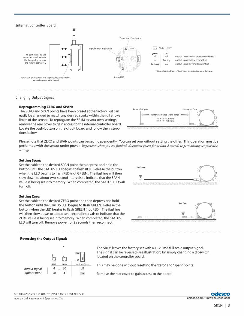
Changing Output Signal
ON
Signal Reversing Switch
Status LED
Zero / Span Pushbutton
to gain access to the controller board, remove the four phillips screws and remove rear cover.
zero/span pushbutton and signal selection switcheslocated on controller board
Internal Controller Board
Setting Span:Set the cable to the desired SPAN point then depress and hold the button until the STATUS LED begins to flash RED. Release the button when the LED begins to flash RED (not GREEN). The flashing will then slow down to about two-second intervals to indicate that the SPAN value is being set into memory. When completed, the STATUS LED will turn off.
Setting Zero:Set the cable to the desired ZERO point and then depress and hold the button until the STATUS LED begins to flash GREEN. Release the button when the LED begins to flash GREEN (not RED). The flashing will then slow down to about two-second intervals to indicate that the ZERO value is being set into memory. When completed, the STATUS LED will turn off. Remove power for 2 seconds then reconnect.
Set Span
Set Zero
Reprogramming ZERO and SPAN:The ZERO and SPAN points have been preset at the factory but can easily be changed to match any desired stroke within the full stroke limits of the sensor. To reprogram the SR1M to your own settings, remove the rear cover to gain access to the internal controller board. Locate the push-button on the circuit board and follow the instruc-tions below.
Please note that ZERO and SPAN points can be set independently. You can set one without setting the other. This operation must be performed with the sensor under power. Important: when you are finished, disconnect power for at least 2 seconds to permanently set your new settings.
Factory Set Span Factory Set Zero
Factory Calibrated Stroke Range
SR1M-125 = 125 inchesSR1M-175 = 175 inches
4 ... 20 o�
20 ... 4 onoutput signaloptions (mA)
switch settingszero span
o�
on
The SR1M leaves the factory set with a 4...20 mA full scale output signal. The signal can be reversed (see illustration) by simply changing a dipswitch located on the controller board.
This may be done without resetting the “zero” and “span” points.
Remove the rear cover to gain access to the board.
Reversing the Output Signal:
green red
Status LED**
o� o�
on �ashing
�ashing on
output signal within programmed limitsoutput signal below zero setting
output signal beyond span setting
**Note: Flashing Status LED will cause the output signal to �uctuate.

4 | SR1M
tel: 800.423.5483 • +1.818.701.2750 • fax: +1.818.701.2799
now part of Measurement Specialties, Inc.
A
Ø 4
.49
[114
,0]
5.50 [139,7]
4.76 [120,9]
3.61 [91,7]
3.64 ±.13[92,5 ±3,3]
1.391 [35,32]
3.85 [97,8] max.
1.18 [30,0]
Ø.265 [6,73]4 places
.84 [21,3]
.96 [24,4]
.65 [16,5]
6.00 [152,4]
.75 [19,0]
.60 [15,2] 1.59 [40,4]
AModel
175-inch 4.54 ±.13[115,3 ±3,3]
125-inch
Fig. 2 - “Up” Cable Exit Direction
Fig. 1 - Outline Drawing (as shipped)
A
B
Ø 4
.49
[114
,0]
* tolerance = +.005 –.001 [+.13 –.03] ** tolerance = +.005 –.005 [+.13 –.13]
Eyelet Detail
Cable Guide Detail
Ø.191 [4,85]*Ø.375 [9,52]**
.165 [4,19]
2.00 ±.13[50,8 ±3,3]
5.50 [139,7]
4.76 [120,9]
2.37 ±.13[60,22 ±3,3]
2.91 [73,9]
0.70 [17,8]
2.50[63,5]
1.39[35,3]
3.85 [97,8] max.
1.18 [30,0]6.00 [152,4]
Ø.265 [6,73]4 places
.84 [21,3]
.65 [16,5]
.75 [19,0]
units are in inches [mm] tolerances are ± .04 [1,0] unless otherwise noted
2.87 ±.13[72,8 ±3,2]
3.24 ±.13[82.2 ±3,2]
A B
125-inch
Model
175-inch
.90[22,8]
.52[13,2]
2.37[60,1]1.50[38]
Ø.53[13,4]
175-inch
62-inch & 125-inch
celesco.com • [email protected]

SR1M | 5
tel: 800.423.5483 • +1.818.701.2750 • fax: +1.818.701.2799
now part of Measurement Specialties, Inc.
A
Ø 4
.49
[114
,0]
5.50 [139,7]
4.76 [120,9]
2.25 ±.13[57,2 ±3,3]
1.39 [35,3]
3.85 [97,8] max.
1.18 [30,0]
Ø.265 [6,73]4 places
.84 [21,3]
.95 [24,1]
3.61 [91,7]
.65 [16,5]
bottom cable exit location
.75 [19,0]
.58 [14,7] 1.59 [40,4]
AModel
175-inch3.17 ±.13
[80,5 ±3,3]
125-inch
Fig. 3 - “Down” Cable Exit Direction
1.59 [40,4]
Ø 4
.49
[114
.0]
5.50 [139,7]
4.76 [120,9]
4.30
[10
9,2]
2.50
[63
,5]
1.39 [35,3]
3.85 [97,8] max.
1.18 [30,0]
Ø.265 [6,73]4 places
.84 [21,3]
.65 [16,5]
6.00 [152,4]
3.61
[91
,7]
.75 [19,0]
2.00 ±.13[50,8 ±3,3]
2.37 ±.13[60,22 ±3,3]
2.87 ±.13[72,8 ±3,2]
3.24 ±.13[82.2 ±3,2]
AA B
B
Model
175-inch
125-inch
units are in inches [mm] tolerances are ± .04 [1,0] unless otherwise noted
Fig. 4 - “Rear” Cable Exit Direction
celesco.com • [email protected]
version: 4.0 last updated: March 5, 2013