usemaintancemanual nef mechinjection l31900009e oct05
TRANSCRIPT
1
EN
GL
ISH
NEF SERIESMECHANICAL INJECTION SYSTEM N45 MNA - N45 MSA (TIER 2)N45 MNS - N45 MSS (TIER 2/3)N45 MNT - N45 MST (TIER 2/3)N67 MNT - N67 MST (TIER 2/3)NEF 45 TM1 NEF 45 TM2NEF 67 SM1NEF 67 TM2NEF 67 TM3
USE AND MAINTENANCE
INTRODUCTIONWe would like to thank you for buying an IVECO MOTORS product,and compliment you on your choice of engine.Before you carry out any operation involving the engine or its fittings,please read the contents of this manual carefully; compliance with theinstructions provided in the manual is the best way to guaranteetrouble-free, long term operation of the engine.
The contents of this manual refer to the standard configuration of theengine, and the illustrations are purely indicative. Some instructions areprovided by giving the sequence of operations to be carried out inorder to allow the engine and/or its fittings to perform in a certain way.In some cases they will be dependent on the configuration of thecommands and the set-up of the machine on which the engine isinstalled; for any points that differ from the contents of this manual,please consult the instructions provided by the machine Manufactureror a specific manual.The information provided below was current at the date ofpublication.The Manufacturer reserves the right to make modifications at any timewithout prior notice, for technical or commercial reasons or to updatethe engines to comply with legal requirements in the variousCountries.The Manufacturer declines all liability for any errors or omissions.
Please remember that the IVECO MOTORS Technical ServiceNetwork is available to offer you its experience and professional skills,wherever you may be.
2
TABLE OF CONTENTS PageGENERAL INFORMATION . . . . . . . . . . . . . . . . . . . . . . . . . . . . . .3Guarantee . . . . . . . . . . . . . . . . . . . . . . . . . . . . . . . . . . . . . . . . . . . . . .3Spare Parts . . . . . . . . . . . . . . . . . . . . . . . . . . . . . . . . . . . . . . . . . . . . .3Liability . . . . . . . . . . . . . . . . . . . . . . . . . . . . . . . . . . . . . . . . . . . . . . . . .3Safety . . . . . . . . . . . . . . . . . . . . . . . . . . . . . . . . . . . . . . . . . . . . . . . . . .3Engine technical data N45 MNA - N45 MSA. . . . . . . . . . . . . . . . .4Engine technical data N45 MNS / MSS / MNT / MST . . . . . . . . . .6Engine technical data N67 MNT - N67 MST . . . . . . . . . . . . . . . . .8Engine technical data NEF 45 TM1 / TM2. . . . . . . . . . . . . . . . . . .10Engine technical data NEF 67 SM1. . . . . . . . . . . . . . . . . . . . . . . . .12Engine technical data NEF 67 TM2 / TM3. . . . . . . . . . . . . . . . . . .14Signs . . . . . . . . . . . . . . . . . . . . . . . . . . . . . . . . . . . . . . . . . . . . . . . . . .16USE . . . . . . . . . . . . . . . . . . . . . . . . . . . . . . . . . . . . . . . . . . . . . . . . . . .17Preliminary checks. . . . . . . . . . . . . . . . . . . . . . . . . . . . . . . . . . . . . . .17 Starting and stopping the engine . . . . . . . . . . . . . . . . . . . . . . . . . . .17Recognising alarms . . . . . . . . . . . . . . . . . . . . . . . . . . . . . . . . . . . . . .20Engine pre-heating . . . . . . . . . . . . . . . . . . . . . . . . . . . . . . . . . . . . . .21For proper use of the engine . . . . . . . . . . . . . . . . . . . . . . . . . . . . .21Special warnings . . . . . . . . . . . . . . . . . . . . . . . . . . . . . . . . . . . . . . . .22 Running in . . . . . . . . . . . . . . . . . . . . . . . . . . . . . . . . . . . . . . . . . . . . .23 Refuelling . . . . . . . . . . . . . . . . . . . . . . . . . . . . . . . . . . . . . . . . . . . . . .24 CONTROLS AND MAINTENANCE . . . . . . . . . . . . . . . . . . . . .25Maintenance personnel . . . . . . . . . . . . . . . . . . . . . . . . . . . . . . . . . .25Accident prevention . . . . . . . . . . . . . . . . . . . . . . . . . . . . . . . . . . . . .25Frequency . . . . . . . . . . . . . . . . . . . . . . . . . . . . . . . . . . . . . . . . . . . . .26Requirements . . . . . . . . . . . . . . . . . . . . . . . . . . . . . . . . . . . . . . . . . .27How to proceed. . . . . . . . . . . . . . . . . . . . . . . . . . . . . . . . . . . . . . . .28Moving the engine . . . . . . . . . . . . . . . . . . . . . . . . . . . . . . . . . . . . . .36Disposal of waste . . . . . . . . . . . . . . . . . . . . . . . . . . . . . . . . . . . . . . .36
PageLONG PERIODS OF INACTIVITY . . . . . . . . . . . . . . . . . . . . . . .37
Preparing the engine for a long period of inactivity . . . . . . . . . . .37Restarting the engine after a long period of inactivity . . . . . . . . .38BEHAVIOUR IN AN EMERGENCY. . . . . . . . . . . . . . . . . . . . . . .39IN APPENDIX . . . . . . . . . . . . . . . . . . . . . . . . . . . . . . . . . . . . . . . . . . .Oil viscosity level according to surrounding temperatures . . . . . . .
3
EN
GL
ISH
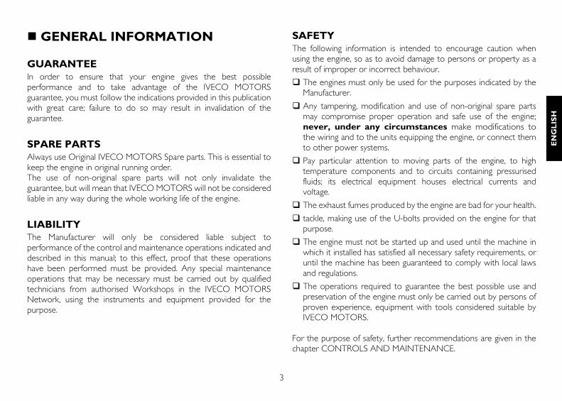
GENERAL INFORMATION
GUARANTEEIn order to ensure that your engine gives the best possibleperformance and to take advantage of the IVECO MOTORSguarantee, you must follow the indications provided in this publicationwith great care; failure to do so may result in invalidation of theguarantee.
SPARE PARTSAlways use Original IVECO MOTORS Spare parts. This is essential tokeep the engine in original running order.The use of non-original spare parts will not only invalidate theguarantee, but will mean that IVECO MOTORS will not be consideredliable in any way during the whole working life of the engine.
LIABILITYThe Manufacturer will only be considered liable subject toperformance of the control and maintenance operations indicated anddescribed in this manual; to this effect, proof that these operationshave been performed must be provided. Any special maintenanceoperations that may be necessary must be carried out by qualifiedtechnicians from authorised Workshops in the IVECO MOTORSNetwork, using the instruments and equipment provided for thepurpose.
SAFETYThe following information is intended to encourage caution whenusing the engine, so as to avoid damage to persons or property as aresult of improper or incorrect behaviour.
The engines must only be used for the purposes indicated by theManufacturer.
Any tampering, modification and use of non-original spare partsmay compromise proper operation and safe use of the engine;never, under any circumstances make modifications tothe wiring and to the units equipping the engine, or connect themto other power systems.
Pay particular attention to moving parts of the engine, to hightemperature components and to circuits containing pressurisedfluids; its electrical equipment houses electrical currents andvoltage.
The exhaust fumes produced by the engine are bad for your health.
tackle, making use of the U-bolts provided on the engine for thatpurpose.
The engine must not be started up and used until the machine inwhich it installed has satisfied all necessary safety requirements, oruntil the machine has been guaranteed to comply with local lawsand regulations.
The operations required to guarantee the best possible use andpreservation of the engine must only be carried out by persons ofproven experience, equipment with tools considered suitable byIVECO MOTORS.
For the purpose of safety, further recommendations are given in thechapter CONTROLS AND MAINTENANCE.
4
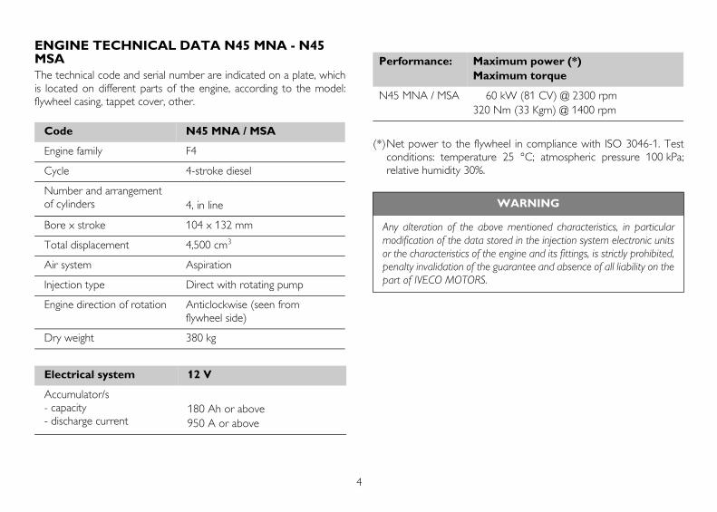
ENGINE TECHNICAL DATA N45 MNA - N45 MSAThe technical code and serial number are indicated on a plate, whichis located on different parts of the engine, according to the model:flywheel casing, tappet cover, other.
(*)Net power to the flywheel in compliance with ISO 3046-1. Testconditions: temperature 25 °C; atmospheric pressure 100 kPa;relative humidity 30%.
Code N45 MNA / MSA
Engine family F4
Cycle 4-stroke diesel
Number and arrangement of cylinders 4, in line
Bore x stroke 104 x 132 mm
Total displacement 4,500 cm3
Air system Aspiration
Injection type Direct with rotating pump
Engine direction of rotation Anticlockwise (seen from flywheel side)
Dry weight 380 kg
Electrical system 12 V
Accumulator/s- capacity- discharge current
180 Ah or above950 A or above
Performance: Maximum power (*)Maximum torque
N45 MNA / MSA 60 kW (81 CV) @ 2300 rpm320 Nm (33 Kgm) @ 1400 rpm
WARNING
Any alteration of the above mentioned characteristics, in particularmodification of the data stored in the injection system electronic unitsor the characteristics of the engine and its fittings, is strictly prohibited,penalty invalidation of the guarantee and absence of all liability on thepart of IVECO MOTORS.
5
EN
GL
ISH
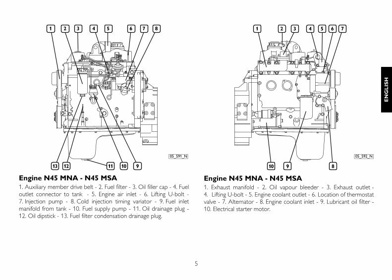
Engine N45 MNA - N45 MSA1. Auxiliary member drive belt - 2. Fuel filter - 3. Oil filler cap - 4. Fueloutlet connector to tank - 5. Engine air inlet - 6. Lifting U-bolt -7. Injection pump - 8. Cold injection timing variator - 9. Fuel inletmanifold from tank - 10. Fuel supply pump - 11. Oil drainage plug -12. Oil dipstick - 13. Fuel filter condensation drainage plug.
Engine N45 MNA - N45 MSA1. Exhaust manifold - 2. Oil vapour bleeder - 3. Exhaust outlet -4. Lifting U-bolt - 5. Engine coolant outlet - 6. Location of thermostatvalve - 7. Alternator - 8. Engine coolant inlet - 9. Lubricant oil filter -10. Electrical starter motor.
05_591_N 05_592_N

6
ENGINE TECHNICAL DATA N45 MNS/MSS/MNT/MSTThe technical code and serial number are indicated on a plate, whichis located on different parts of the engine, according to the model:flywheel casing, tappet cover, other.
(1) Only for N45 MNT / MST engines
(*)Net power to the flywheel in compliance with ISO 3046-1. Testconditions: temperature 25 °C; atmospheric pressure 100 kPa;relative humidity 30%.
Code N45 MNS / MSS / MNT / MST
Engine family F4
Cycle 4-stroke diesel
Number and arrangement of cylinders 4, in line
Bore x stroke 104 x 132 mm
Total displacement 4,500 cm3
Air system Supercharged - Aftercooled (1)
Injection type Direct with rotating pump
Engine direction of rotation Anticlockwise (seen from flywheel side)
Dry weight 390 kg
Electrical system 12 V
Accumulator/s- capacity- discharge current
180 Ah or above950 A or above
Performance: Maximum power (*)Maximum torque
N45 MNS / MSS 74 kW (100 CV) @ 2300 rpm398 Nm (40.5 Kgm) @ 1400 rpm
N45 MNT / MST 94 kW (128 CV) @ 2300 rpm500 Nm (50.9 Kgm) @ 1400 rpm
WARNING
Any alteration of the above mentioned characteristics, in particularmodification of the data stored in the injection system electronic unitsor the characteristics of the engine and its fittings, is strictly prohibited,penalty invalidation of the guarantee and absence of all liability on thepart of IVECO MOTORS.
7
EN
GL
ISH
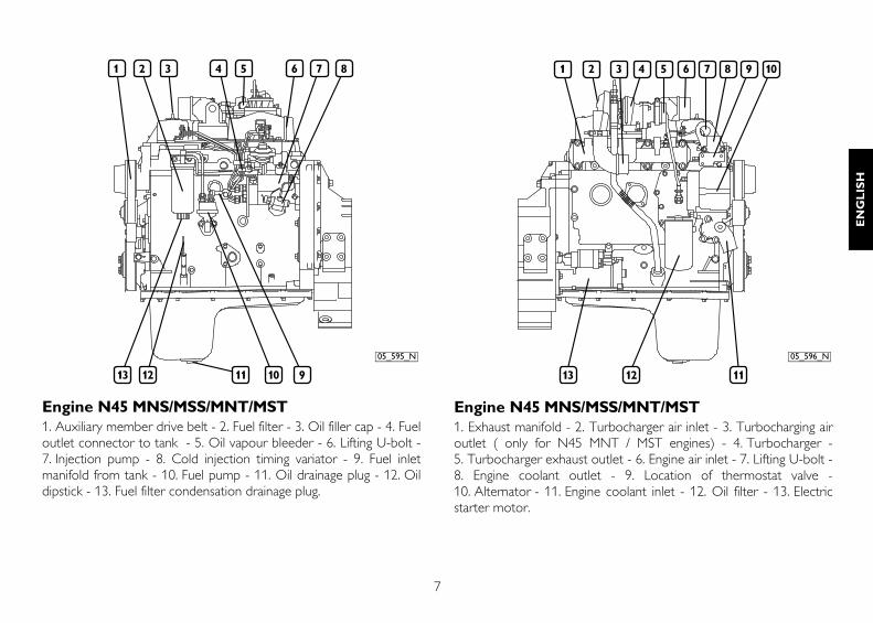
Engine N45 MNS/MSS/MNT/MST1. Auxiliary member drive belt - 2. Fuel filter - 3. Oil filler cap - 4. Fueloutlet connector to tank - 5. Oil vapour bleeder - 6. Lifting U-bolt -7. Injection pump - 8. Cold injection timing variator - 9. Fuel inletmanifold from tank - 10. Fuel pump - 11. Oil drainage plug - 12. Oildipstick - 13. Fuel filter condensation drainage plug.
Engine N45 MNS/MSS/MNT/MST1. Exhaust manifold - 2. Turbocharger air inlet - 3. Turbocharging airoutlet ( only for N45 MNT / MST engines) - 4. Turbocharger -5. Turbocharger exhaust outlet - 6. Engine air inlet - 7. Lifting U-bolt -8. Engine coolant outlet - 9. Location of thermostat valve -10. Alternator - 11. Engine coolant inlet - 12. Oil filter - 13. Electricstarter motor.
05_595_N 05_596_N
8
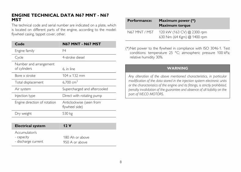
ENGINE TECHNICAL DATA N67 MNT - N67 MSTThe technical code and serial number are indicated on a plate, whichis located on different parts of the engine, according to the model:flywheel casing, tappet cover, other.
(*)Net power to the flywheel in compliance with ISO 3046-1. Testconditions: temperature 25 °C; atmospheric pressure 100 kPa;relative humidity 30%.
Code N67 MNT - N67 MST
Engine family F4
Cycle 4-stroke diesel
Number and arrangement of cylinders 6, in line
Bore x stroke 104 x 132 mm
Total displacement 6,700 cm3
Air system Supercharged and aftercooled
Injection type Direct with rotating pump
Engine direction of rotation Anticlockwise (seen from flywheel side)
Dry weight 530 kg
Electrical system 12 V
Accumulator/s- capacity- discharge current
180 Ah or above950 A or above
Performance: Maximum power (*)Maximum torque
N67 MNT / MST 120 kW (163 CV) @ 2300 rpm630 Nm (64 Kgm) @ 1400 rpm
WARNING
Any alteration of the above mentioned characteristics, in particularmodification of the data stored in the injection system electronic unitsor the characteristics of the engine and its fittings, is strictly prohibited,penalty invalidation of the guarantee and absence of all liability on thepart of IVECO MOTORS.
9
EN
GL
ISH
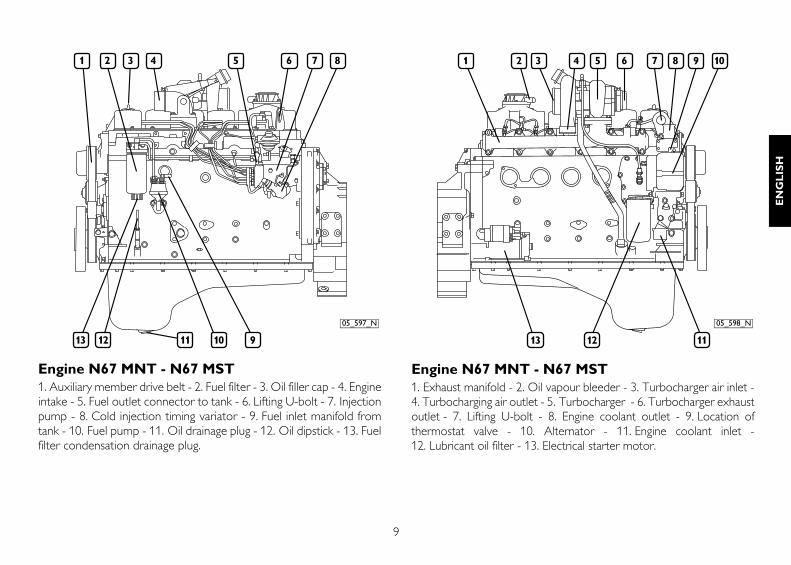
Engine N67 MNT - N67 MST1. Auxiliary member drive belt - 2. Fuel filter - 3. Oil filler cap - 4. Engineintake - 5. Fuel outlet connector to tank - 6. Lifting U-bolt - 7. Injectionpump - 8. Cold injection timing variator - 9. Fuel inlet manifold fromtank - 10. Fuel pump - 11. Oil drainage plug - 12. Oil dipstick - 13. Fuelfilter condensation drainage plug.
Engine N67 MNT - N67 MST1. Exhaust manifold - 2. Oil vapour bleeder - 3. Turbocharger air inlet -4. Turbocharging air outlet - 5. Turbocharger - 6. Turbocharger exhaustoutlet - 7. Lifting U-bolt - 8. Engine coolant outlet - 9. Location ofthermostat valve - 10. Alternator - 11. Engine coolant inlet -12. Lubricant oil filter - 13. Electrical starter motor.
05_597_N 05_598_N
10
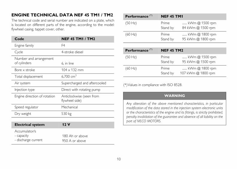
ENGINE TECHNICAL DATA NEF 45 TM1 / TM2The technical code and serial number are indicated on a plate, whichis located on different parts of the engine, according to the model:flywheel casing, tappet cover, other.
(*)Values in compliance with ISO 8528.
Code NEF 45 TM1 / TM2
Engine family F4
Cycle 4-stroke diesel
Number and arrangement of cylinders 6, in line
Bore x stroke 104 x 132 mm
Total displacement 6,700 cm3
Air system Supercharged and aftercooled
Injection type Direct with rotating pump
Engine direction of rotation Anticlockwise (seen from flywheel side)
Speed regulator Mechanical
Dry weight 530 kg
Electrical system 12 V
Accumulator/s- capacity- discharge current
180 Ah or above950 A or above
Performance (*) NEF 45 TM1
(50 Hz) Prime ....... kWm @ 1500 rpmStand by 84 kWm @ 1500 rpm
(60 Hz) Prime ....... kWm @ 1800 rpmStand by 95 kWm @ 1800 rpm
Performance (*) NEF 45 TM2
(50 Hz) Prime ....... kWm @ 1500 rpmStand by 95 kWm @ 1500 rpm
(60 Hz) Prime ....... kWm @ 1800 rpmStand by 107 kWm @ 1800 rpm
WARNING
Any alteration of the above mentioned characteristics, in particularmodification of the data stored in the injection system electronic unitsor the characteristics of the engine and its fittings, is strictly prohibited,penalty invalidation of the guarantee and absence of all liability on thepart of IVECO MOTORS.
11
EN
GL
ISH
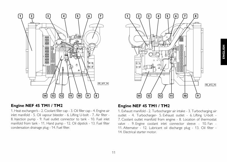
Engine NEF 45 TM1 / TM21. Heat exchanger/s - 2. Coolant filler cap - 3. Oil filler cap - 4. Engine airinlet manifold - 5. Oil vapour bleeder - 6. Lifting U-bolt - 7. Air filter -8. Injection pump - 9. Fuel outlet connector to tank - 10. Fuel inletmanifold from tank - 11. Hand pump - 12. Oil dipstick - 13. Fuel filtercondensation drainage plug - 14. Fuel filter.
Engine NEF 45 TM1 / TM21. Exhaust manifold - 2. Turbocharger air intake - 3. Turbocharging airoutlet - 4. Turbocharger- 5. Exhaust outlet - 6. Lifting U-bolt -7. Coolant outlet manifold from engine - 8. Location of thermostatvalve - 9. Engine coolant inlet connector sleeve - 10. Fan -11. Alternator - 12. Lubricant oil discharge plug - 13. Oil filter -14. Electrical starter motor.
05_611_N 05_612_N
12
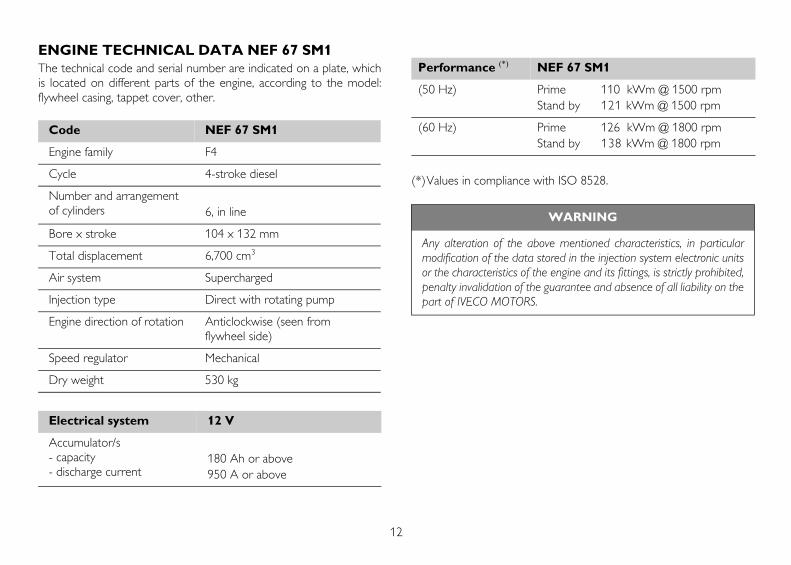
ENGINE TECHNICAL DATA NEF 67 SM1The technical code and serial number are indicated on a plate, whichis located on different parts of the engine, according to the model:flywheel casing, tappet cover, other.
(*)Values in compliance with ISO 8528.
Code NEF 67 SM1
Engine family F4
Cycle 4-stroke diesel
Number and arrangement of cylinders 6, in line
Bore x stroke 104 x 132 mm
Total displacement 6,700 cm3
Air system Supercharged
Injection type Direct with rotating pump
Engine direction of rotation Anticlockwise (seen from flywheel side)
Speed regulator Mechanical
Dry weight 530 kg
Electrical system 12 V
Accumulator/s- capacity- discharge current
180 Ah or above950 A or above
Performance (*) NEF 67 SM1
(50 Hz) Prime 110 kWm @ 1500 rpmStand by 121 kWm @ 1500 rpm
(60 Hz) Prime 126 kWm @ 1800 rpmStand by 138 kWm @ 1800 rpm
WARNING
Any alteration of the above mentioned characteristics, in particularmodification of the data stored in the injection system electronic unitsor the characteristics of the engine and its fittings, is strictly prohibited,penalty invalidation of the guarantee and absence of all liability on thepart of IVECO MOTORS.
13
EN
GL
ISH
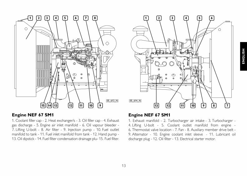
Engine NEF 67 SM11. Coolant filler cap - 2. Heat exchanger/s - 3. Oil filler cap - 4. Exhaustgas discharge - 5. Engine air inlet manifold - 6. Oil vapour bleeder -7. Lifting U-bolt - 8. Air filter - 9. Injection pump - 10. Fuel outletmanifold to tank - 11. Fuel inlet manifold from tank - 12. Hand pump -13. Oil dipstick - 14. Fuel filter condensation drainage plu- 15. Fuel filter.
Engine NEF 67 SM11. Exhaust manifold - 2. Turbocharger air intake - 3. Turbocharger -4. Lifting U-bolt - 5. Coolant outlet manifold from engine -6. Thermostat valve location - 7. Fan - 8. Auxiliary member drive belt -9. Alternator - 10. Engine coolant inlet sleeve - 11. Lubricant oildischarge plug - 12. Oil filter - 13. Electrical starter motor.
05_613_N 05_614_N

14
ENGINE TECHNICAL DATA NEF 67 TM2 / TM3The technical code and serial number are indicated on a plate, whichis located on different parts of the engine, according to the model:flywheel casing, tappet cover, other.
(*)Values in compliance with ISO 8528.
Code NEF 67 TM2 - NEF 67 TM3
Engine family F4
Cycle 4-stroke diesel
Number and arrangement of cylinders 6, in line
Bore x stroke 104 x 132 mm
Total displacement 6,700 cm3
Air system Supercharged and aftercooled
Injection type Direct with rotating pump
Engine direction of rotation Anticlockwise (seen from flywheel side)
Speed regulator Mechanical
Dry weight 530 kg
Electrical system 12 V
Accumulator/s- capacity- discharge current
180 Ah or above950 A or above
Performance (*) NEF 67 TM2
(50 Hz) Prime 114 kWm @ 1500 rpmStand by 125 kWm @ 1500 rpm
(60 Hz) Prime 127 kWm @ 1800 rpmStand by 140 kWm @ 1800 rpm
Performance (*) NEF 67 TM3
(50 Hz) Prime 138 kWm @ 1500 rpmStand by 152 kWm @ 1500 rpm
(60 Hz) Prime 150 kWm @ 1800 rpmStand by 165 kWm @ 1800 rpm
WARNING
Any alteration of the above mentioned characteristics, in particularmodification of the data stored in the injection system electronic unitsor the characteristics of the engine and its fittings, is strictly prohibited,penalty invalidation of the guarantee and absence of all liability on thepart of IVECO MOTORS.
15
EN
GL
ISH
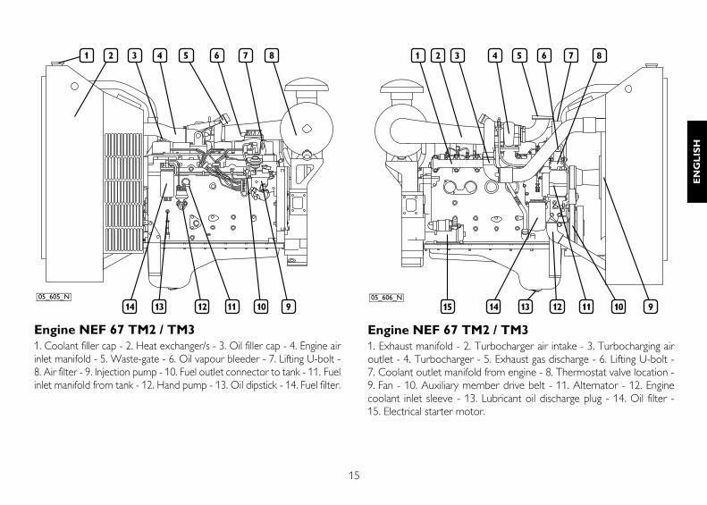
Engine NEF 67 TM2 / TM31. Coolant filler cap - 2. Heat exchanger/s - 3. Oil filler cap - 4. Engine airinlet manifold - 5. Waste-gate - 6. Oil vapour bleeder - 7. Lifting U-bolt -8. Air filter - 9. Injection pump - 10. Fuel outlet connector to tank - 11. Fuelinlet manifold from tank - 12. Hand pump - 13. Oil dipstick - 14. Fuel filter.
Engine NEF 67 TM2 / TM31. Exhaust manifold - 2. Turbocharger air intake - 3. Turbocharging airoutlet - 4. Turbocharger - 5. Exhaust gas discharge - 6. Lifting U-bolt -7. Coolant outlet manifold from engine - 8. Thermostat valve location -9. Fan - 10. Auxiliary member drive belt - 11. Alternator - 12. Enginecoolant inlet sleeve - 13. Lubricant oil discharge plug - 14. Oil filter -15. Electrical starter motor.
05_605_N 05_606_N
16
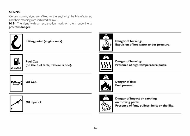
SIGNSCertain warning signs are affixed to the engine by the Manufacturer,and their meanings are indicated belowN.B. The signs with an exclamation mark on them underline apotential danger.
Lifting point (engine only).
Fuel Cap (on the fuel tank, if there is one).
Oil Cap.
Oil dipstick.
Danger of burning: Expulsion of hot water under pressure.
Danger of burning: Presence of high temperature parts.
Danger of fire: Fuel present.
Danger of impact or catching on moving parts: Presence of fans, pulleys, belts or the like.
17
EN
GL
ISH
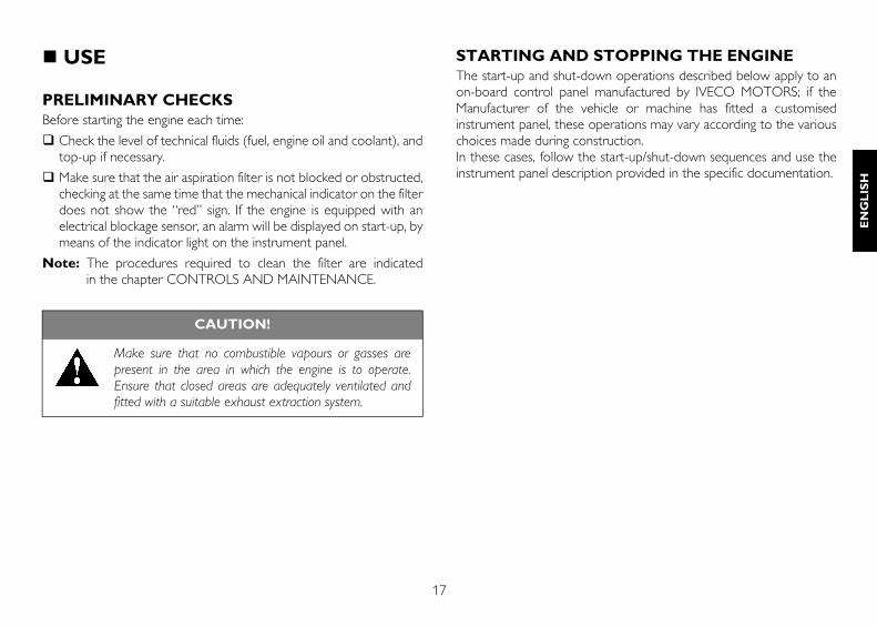
USE
PRELIMINARY CHECKSBefore starting the engine each time:
Check the level of technical fluids (fuel, engine oil and coolant), andtop-up if necessary.
Make sure that the air aspiration filter is not blocked or obstructed,checking at the same time that the mechanical indicator on the filterdoes not show the “red” sign. If the engine is equipped with anelectrical blockage sensor, an alarm will be displayed on start-up, bymeans of the indicator light on the instrument panel.
Note: The procedures required to clean the filter are indicated in the chapter CONTROLS AND MAINTENANCE.
STARTING AND STOPPING THE ENGINE The start-up and shut-down operations described below apply to anon-board control panel manufactured by IVECO MOTORS; if theManufacturer of the vehicle or machine has fitted a customisedinstrument panel, these operations may vary according to the variouschoices made during construction.In these cases, follow the start-up/shut-down sequences and use theinstrument panel description provided in the specific documentation.
CAUTION!
Make sure that no combustible vapours or gasses arepresent in the area in which the engine is to operate.Ensure that closed areas are adequately ventilated andfitted with a suitable exhaust extraction system.
18
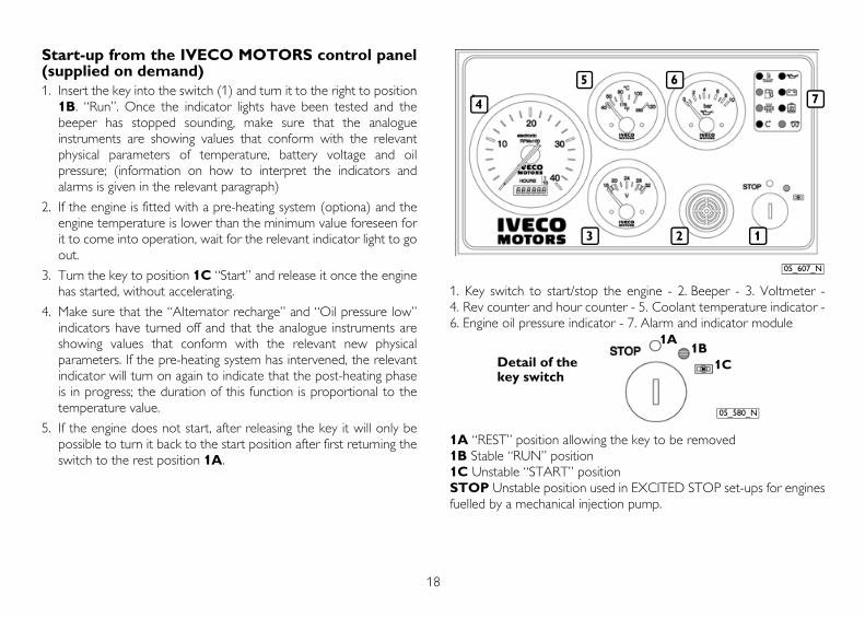
Start-up from the IVECO MOTORS control panel(supplied on demand)1. Insert the key into the switch (1) and turn it to the right to position
1B. “Run”. Once the indicator lights have been tested and thebeeper has stopped sounding, make sure that the analogueinstruments are showing values that conform with the relevantphysical parameters of temperature, battery voltage and oilpressure; (information on how to interpret the indicators andalarms is given in the relevant paragraph)
2. If the engine is fitted with a pre-heating system (optiona) and theengine temperature is lower than the minimum value foreseen forit to come into operation, wait for the relevant indicator light to goout.
3. Turn the key to position 1C “Start” and release it once the enginehas started, without accelerating.
4. Make sure that the “Alternator recharge” and “Oil pressure low”indicators have turned off and that the analogue instruments areshowing values that conform with the relevant new physicalparameters. If the pre-heating system has intervened, the relevantindicator will turn on again to indicate that the post-heating phaseis in progress; the duration of this function is proportional to thetemperature value.
5. If the engine does not start, after releasing the key it will only bepossible to turn it back to the start position after first returning theswitch to the rest position 1A.
1. Key switch to start/stop the engine - 2. Beeper - 3. Voltmeter -4. Rev counter and hour counter - 5. Coolant temperature indicator -6. Engine oil pressure indicator - 7. Alarm and indicator module
1A “REST” position allowing the key to be removed1B Stable “RUN” position1C Unstable “START” positionSTOP Unstable position used in EXCITED STOP set-ups for enginesfuelled by a mechanical injection pump.
123
4
5 6
7
05_607_N
1A1B
1C
05_580_N
Detail of the key switch
19
EN
GL
ISH
Start-up of a power generatorThe start-up method described above may vary, depending on thesolutions used to create the electric panels and the system control andrunning boards; so you should always comply with the indicationsprovided by the Fitter of the power generating plants or theManufacturer of the machine, even if the panels and control stationshave been created using the same components used for IVECOMOTORS panels.In any case, after start-up the engine will automatically revert to theselected running speed.It is suggested that the engine be warmed up with a reduced loadbefore applying the full load (*).
(*) With the exception of the emergency power generators, for whichthe operating limits indicated in the commercial documentationapply and for which the use of a pre-heating device is required (seefollowing pages).
Stopping the engine from the IVECO MOTORScontrol panel Before stopping the engine it is recommended you run it for a fewminutes at minimum speed with no load; this will allow thetemperature to drop evenly and will avoid harmful thermal shocks.
The shutdown method will depend on the type of equipment installed.
With “unexcited” stop circuit
- Turn the key switch to position 1A - REST. With “excited” stop circuit
- Turn the key switch to the STOP position.
In the absence of IVECO MOTORS control panels, always follow theinstructions provided by the Manufacturer of the machine.
Should you intend to re-start the engine:
1. Return the key switch to the rest position 1A, thus resetting all theon-board panel functions (only essential for electronicallycontrolled engines).
2. Turn the key to position 1C “Start” and release it once the enginehas started, without accelerating.
3. Proceed as described previously.
CAUTION!
The emergency power generator may start up at any time.During maintenance operations it is therefore essentialthat all the safety precautions set down by theManufacturer of the generator or the Preparer of thesystem in which it is fitted be closely followed.
20
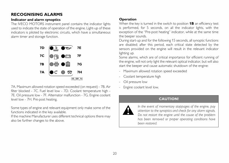
RECOGNISING ALARMSIndicator and alarm synopticsThe IVECO MOTORS instrument panel contains the indicator lightsused to indicate the state of operation of the engine. Light-up of theseindicators is piloted by electronic circuits, which have a simultaneousalarm timer and storage function.
7A. Maximum allowed rotation speed exceeded (on request) - 7B. Airfilter blocked - 7C. Fuel level low - 7D. Coolant temperature high -7E. Oil pressure low - 7F. Alternator malfunction - 7G. Engine coolantlevel low - 7H. Pre-post heating.
Some types of engine and relevant equipment only make some of thefunctions indicated in the key available.If the machine Manufacturer uses different technical options there mayalso be further changes to the above.
OperationWhen the key is turned in the switch to position 1B an efficiency testis performed, for 5 seconds, on all the indicator lights, with theexception of the “Pre-post heating” indicator, while at the same timethe beeper sounds.During start-up and for the following 15 seconds, all synoptic functionsare disabled; after this period, each critical state detected by thesensors provided on the engine will result in the relevant indicatorlighting up.Some alarms, which are of critical importance for efficient running ofthe engine, will not only light the relevant optical indicator, but will alsostart the beeper and cause automatic shutdown of the engine:
- Maximum allowed rotation speed exceeded
- Coolant temperature high
- Oil pressure low
- Engine coolant level low.
7D
7C
7B
7A 7H
7G
7F
7E
05_581_N
CAUTION!
In the event of momentary stoppages of the engine, payattention to the synoptics and check for any alarm signals.Do not restart the engine until the cause of the problemhas been removed or proper operating conditions havebeen restored.
21
EN
GL
ISH
ENGINE PRE-HEATING (optional)(220 V, single phase electrical device)The engines for which low temperature start-up and immediatedelivery of power are required may be fitted with a 220 V single phaseelectrical heating device, which allows the temperature of the coolantto be raised to or maintained at suitable values. The device is fittedwith a thermostat to cut the power supply when the requiredtemperature is reached.
FOR PROPER USE OF THE ENGINE (with the exception of power generator engines)
Do not leave the key turned to the start position 1C, when theengine has started.
It is not efficient to leave the engine running at minimum speedwhile waiting for it to reach the proper working temperature; it ispreferable that, after approximately one minute from start-up, yougradually increase the engine load.
Do not leave the engine running at minimum speed for long, as thisincreases the production of harmful emissions and does notguarantee the best performance.
The engine speed must be increased and decreased gradually, toallow regular combustion and proper operation of all enginecomponents.
The running speed and power values must comply with thespecifications on the technical and commercial documentation.
During use, periodically check that:
1. The engine coolant temperature does not reach the alarmthreshold.
2. The oil pressure remains within normal values.
If the temperature is considered too high, reduce speed and stop tocheck the state of the cooling system circuits; also check and havechecked:
a) the tension of the auxiliary member drive belt;
b) operation of the thermostat valve;
c) whether or not the heat exchanger is clean.
22
SPECIAL WARNINGS
Coolant circuitWhen a state of “Coolant temperature high” and “Engine coolant levellow” is found, this triggers stoppage of the engine; in these cases, checkthe efficiency of the circuit components, remembering that when theengine is warm, a pressure liable to cause hot liquid to be expelledwith extreme violence is created within the cooling circuits. Thisresults in a danger of burning.
Lubrication circuitWhen a state of “Oil pressure low”, is found, this triggers stoppage ofthe engine; in this case, check the oil level and top up if necessary,following the instructions given in the chapter on CONTROLS ANDMAINTENANCE.If the condition persists, contact an Authorised Service Centre.
Fuel circuitAvoid using the engine with only a small reserve of fuel in the fuel tank;this encourages the formation of condensation and makes it morelikely you will suck up dirt or air, resulting in engine stoppage.
Air intake and exhaust discharge circuitsInspect the cleanliness of the air intake circuit on a regular basis. Themaintenance intervals indicated in this manual vary according to theconditions in which the engine is used.In particularly dusty environments it is necessary to carry outmaintenance at more frequent intervals; with respect to the indicationsprovided in the chapter CONTROLS AND MAINTENANCE.
CAUTION!
Only open the coolant tank cap if strictly necessary, andonly when the engine is cold.
CAUTION!
When refuelling, always pay great care to ensure that nosolid or liquid pollutants enter the fuel tank; you must alsoremember that smoking and live flames are prohibitedwhen refuelling.
CAUTION!
Never loosen the circuit connectors in any way.
23
EN
GL
ISH
Electrical starter systemPeriodically check, particularly during the winter, to ensure that thebatteries are clean and in full working order, checking and topping upas indicated in the chapter CONTROLS AND MAINTENANCEShould it be necessary to replace the batteries, always respect thecapacity and minimum discharge current intensity requirements.
RUNNING INThanks to modern engine construction technology, no particularrunning in procedure is required. However, it is recommended that,for the first 50 hours, you do not use the engine at high power for longperiods.
CAUTION!
Visually check that the exhaust circuit is not blocked ordamaged, so as to prevent dangerous fumes.
CAUTION!
The batteries contain an acid solution that will burn theskin and corrode clothing; when checking them, alwayswear protective clothing, gloves and goggles, do not smokeor use live flames in the vicinity, and make sure that theroom they are housed in is adequately ventilated.
24
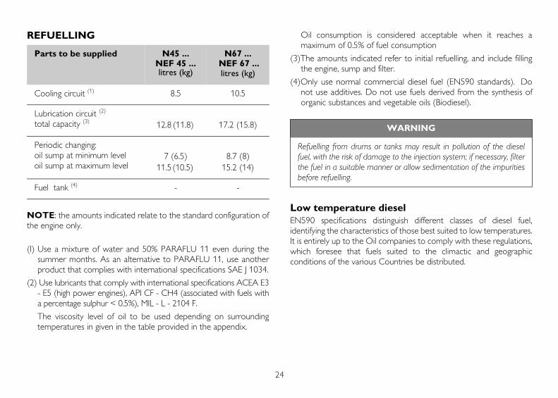
REFUELLING
NOTE: the amounts indicated relate to the standard configuration ofthe engine only.
(I) Use a mixture of water and 50% PARAFLU 11 even during thesummer months. As an alternative to PARAFLU 11, use anotherproduct that complies with international specifications SAE J 1034.
(2) Use lubricants that comply with international specifications ACEA E3- E5 (high power engines), API CF - CH4 (associated with fuels witha percentage sulphur < 0.5%), MIL - L - 2104 F.
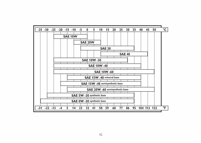
The viscosity level of oil to be used depending on surroundingtemperatures in given in the table provided in the appendix.
Oil consumption is considered acceptable when it reaches amaximum of 0.5% of fuel consumption
(3)The amounts indicated refer to initial refuelling, and include fillingthe engine, sump and filter.
(4)Only use normal commercial diesel fuel (EN590 standards). Donot use additives. Do not use fuels derived from the synthesis oforganic substances and vegetable oils (Biodiesel).
Low temperature dieselEN590 specifications distinguish different classes of diesel fuel,identifying the characteristics of those best suited to low temperatures.It is entirely up to the Oil companies to comply with these regulations,which foresee that fuels suited to the climactic and geographicconditions of the various Countries be distributed.
Parts to be supplied N45 ...NEF 45 ...litres (kg)
N67 ... NEF 67 ...litres (kg)
Cooling circuit (1) 8.5 10.5
Lubrication circuit (2)
total capacity (3) 12.8 (11.8) 17.2 (15.8)
Periodic changing:oil sump at minimum leveloil sump at maximum level
7 (6.5)11.5 (10.5)
8.7 (8)15.2 (14)
Fuel tank (4) - -
WARNING
Refuelling from drums or tanks may result in pollution of the dieselfuel, with the risk of damage to the injection system; if necessary, filterthe fuel in a suitable manner or allow sedimentation of the impuritiesbefore refuelling.
25
EN
GL
ISH
CONTROLS AND MAINTENANCE
MAINTENANCE PERSONNELThe engine control and maintenance operations described in thefollowing chapter require training, experience and compliance withcurrent safety regulations; for this reason they must be carried out byspecial technicians, as indicated below.
Controls: by workshop technicians or the machine user ifnecessary.
Periodic maintenance: by qualified personnelequipped with suitable equipment and adequate meansof protection. Operations marked by the key symbol(see illustration).
Special maintenance: by qualified AuthorisedService Centre staff with specific technical informationand equipment. Operations marked by the key symbol(see illustration).
The Authorised Service Centres are the ones in the IVECO MOTORSTechnical Service Network.
ACCIDENT PREVENTIONAlways wear heavy-duty footwear and overalls.
Never wear loose, flapping garments, rings, bracelets and/ornecklaces in the vicinity of engines or moving parts.
Always wear protective gloves and goggles when:
• filling up batteries with acid solution
• refuelling with inhibitors or antifreeze
• replacing or topping up lubricant (hot engine oil may cause burns andscalds. Only carry out these operations when the oil has dropped toa temperature of below 50°C).
When working in the engine compartment, pay particular attentionto how you move, to avoid contact with moving parts or hightemperature components.
Wear goggles and use high pressure air jets (maximum air pressureused to clean is 200 kPa (2 bar, 30 psi, 2 kg/cm2).
Wear a protective helmet when working in an area were there aresuspended loads or systems installed at head-height.
Use protective hand cremes.
Immediately replace wet overalls.
Always keep the engine clean, removing oil, grease and coolantstains.
Store cloths in flame-proof containers.
Do not leave foreign bodies on the engine.
Use suitable, safe containers for used oil.
When completing a repair, make suitable provisions to stop theengine taking in air if, after start-up, an uncontrolled increase in enginespeed were to occur.
26
FREQUENCY
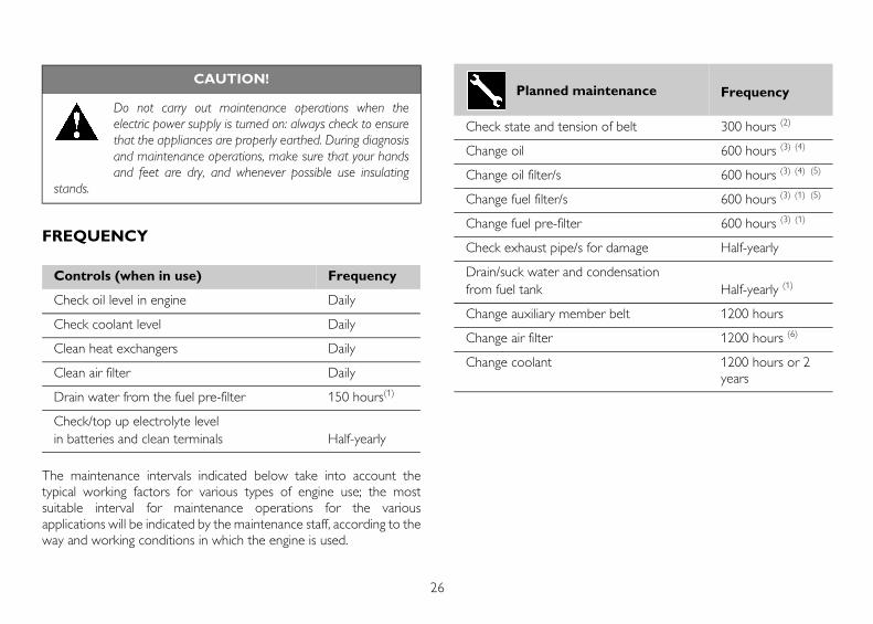
The maintenance intervals indicated below take into account thetypical working factors for various types of engine use; the mostsuitable interval for maintenance operations for the variousapplications will be indicated by the maintenance staff, according to theway and working conditions in which the engine is used.
CAUTION!
Do not carry out maintenance operations when theelectric power supply is turned on: always check to ensurethat the appliances are properly earthed. During diagnosisand maintenance operations, make sure that your handsand feet are dry, and whenever possible use insulating
stands.
Controls (when in use) Frequency
Check oil level in engine Daily
Check coolant level Daily
Clean heat exchangers Daily
Clean air filter Daily
Drain water from the fuel pre-filter 150 hours(1)
Check/top up electrolyte level in batteries and clean terminals Half-yearly
Planned maintenance Frequency
Check state and tension of belt 300 hours (2)
Change oil 600 hours (3) (4)
Change oil filter/s 600 hours (3) (4) (5)
Change fuel filter/s 600 hours (3) (1) (5)
Change fuel pre-filter 600 hours (3) (1)
Check exhaust pipe/s for damage Half-yearly
Drain/suck water and condensationfrom fuel tank Half-yearly (1)
Change auxiliary member belt 1200 hours
Change air filter 1200 hours (6)
Change coolant 1200 hours or 2 years

27
EN
GL
ISH
1) Maximum period when using good quality fuel, (EN 590 standard);this is reduced if the fuel is contaminated and alarms are triggereddue to blockage of the filters and presence of water in the pre-filter.When blockage of the filter is indicated, it must be replaced. If thewater in pre-filter indicator does not go out after drainage, the pre-filter must be replaced.
2) Refers to engines with traditional and automatic tensioning devices
3) Must be performed annually, even if the required number ofworking hours are not reached
4) Replace lubricants according to the frequency indicated in theREFUELLING table.
5) Only use filters with the following characteristics:
- filtration level < 12 µm - filtering efficiency ß > 200.
6) The frequency with which operations are carried out will dependon the working conditions and efficiency/wear of the product.
7) Required by oil vapour recirculation.
REQUIREMENTS1. Do not disconnect the batteries with the engine running.
2. Do not carry out arc welding operations in the vicinity of the enginewithout first removing electrical cables.
3. After each maintenance operation involving disconnection of thebattery/batteries, make sure that the terminals have been properlylocked onto the poles.
4. Do not use battery chargers to start the engine.
5. Disconnect the on-board network battery/batteries whenrecharging.
6. Do not paint the appliances, components and electrical connectorsequipping the engine.
7. Disconnect the battery/batteries before any electrical operations.
8. Contact the Manufacturer before installing electronic equipmenton board (two-way radios and the like).
Special maintenance Frequency
Clean the turbocharger 1200 hours (7)
Check the efficiency of the pre-post heating system (if there is one)
1200 hours
Injector calibration 1800 hours
Overhaul injection pump 3000 hours
Adjust play in valves-rocker arms 3000 hours
28
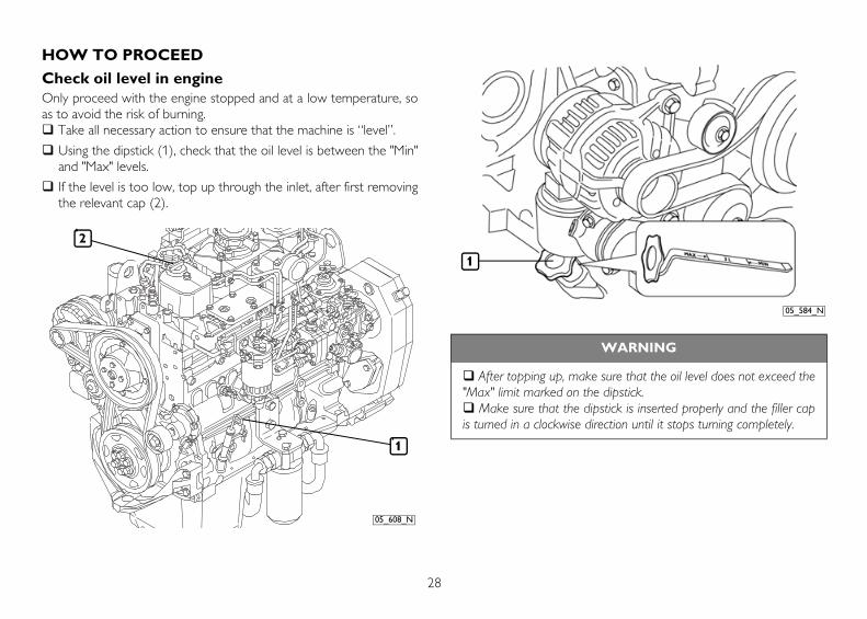
HOW TO PROCEED
Check oil level in engineOnly proceed with the engine stopped and at a low temperature, soas to avoid the risk of burning.
Take all necessary action to ensure that the machine is “level”.
Using the dipstick (1), check that the oil level is between the "Min"and "Max" levels.
If the level is too low, top up through the inlet, after first removingthe relevant cap (2).
05_608_N
2
1
WARNING
After topping up, make sure that the oil level does not exceed the"Max" limit marked on the dipstick.
Make sure that the dipstick is inserted properly and the filler capis turned in a clockwise direction until it stops turning completely.
05_584_N
1
29
EN
GL
ISH
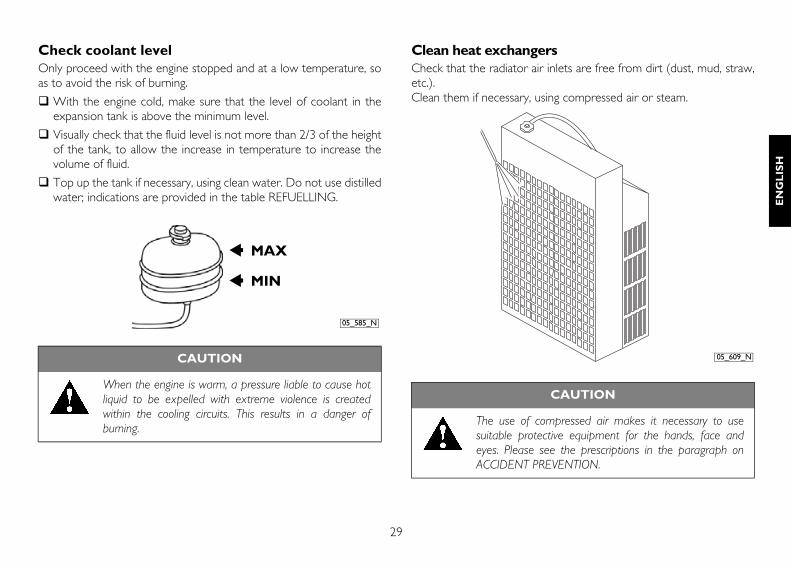
Check coolant levelOnly proceed with the engine stopped and at a low temperature, soas to avoid the risk of burning.
With the engine cold, make sure that the level of coolant in theexpansion tank is above the minimum level.
Visually check that the fluid level is not more than 2/3 of the heightof the tank, to allow the increase in temperature to increase thevolume of fluid.
Top up the tank if necessary, using clean water. Do not use distilledwater; indications are provided in the table REFUELLING.
Clean heat exchangersCheck that the radiator air inlets are free from dirt (dust, mud, straw,etc.). Clean them if necessary, using compressed air or steam.
CAUTION
When the engine is warm, a pressure liable to cause hotliquid to be expelled with extreme violence is createdwithin the cooling circuits. This results in a danger ofburning.
MAX
MIN
05_585_N
CAUTION
The use of compressed air makes it necessary to usesuitable protective equipment for the hands, face andeyes. Please see the prescriptions in the paragraph onACCIDENT PREVENTION.
05_609_N
30
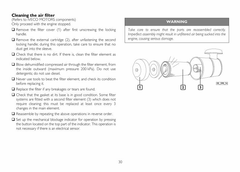
Cleaning the air filter(Refers to IVECO MOTORS components)Only proceed with the engine stopped.
Remove the filter cover (1) after first unscrewing the lockinghandle.
Remove the external cartridge (2), after unfastening the secondlocking handle; during this operation, take care to ensure that nodust get into the sleeve.
Check that there is no dirt. If there is, clean the filter element asindicated below.
Blow dehumidified compressed air through the filter element, fromthe inside outward (maximum pressure 200 kPa). Do not usedetergents; do not use diesel.
Never use tools to beat the filter element, and check its conditionbefore replacing it.
Replace the filter if any breakages or tears are found.
Check that the gasket at its base is in good condition. Some filtersystems are fitted with a second filter element (3) which does notrequire cleaning; this must be replaced at least once every 3changes in the main element.
Reassemble by repeating the above operations in reverse order.
Set up the mechanical blockage indicator for operation by pressingthe button located on the top part of the indicator. This operation isnot necessary if there is an electrical sensor.
WARNING
Take care to ensure that the parts are reassembled correctly.Imperfect assembly might result in unfiltered air being sucked into theengine, causing serious damage.
05_590_N
1 2 3
31
EN
GL
ISH
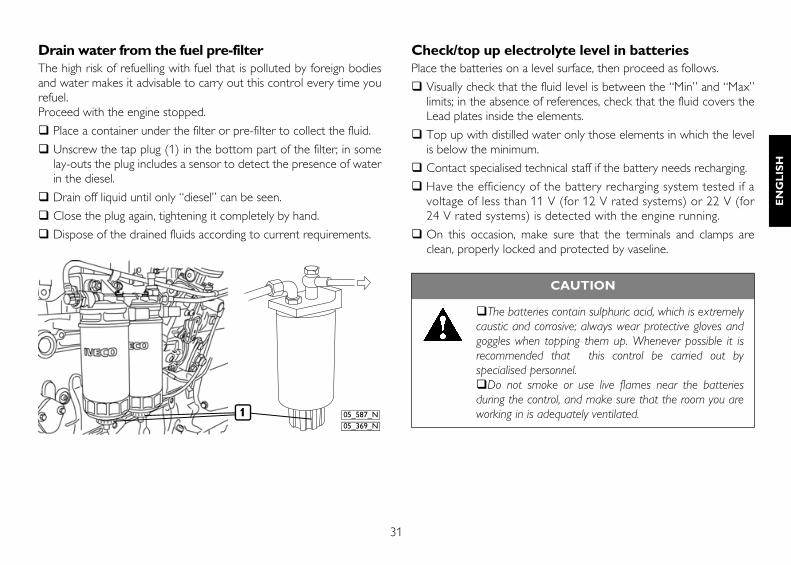
Drain water from the fuel pre-filterThe high risk of refuelling with fuel that is polluted by foreign bodiesand water makes it advisable to carry out this control every time yourefuel.Proceed with the engine stopped.
Place a container under the filter or pre-filter to collect the fluid.
Unscrew the tap plug (1) in the bottom part of the filter; in somelay-outs the plug includes a sensor to detect the presence of waterin the diesel.
Drain off liquid until only “diesel” can be seen.
Close the plug again, tightening it completely by hand.
Dispose of the drained fluids according to current requirements.
Check/top up electrolyte level in batteries Place the batteries on a level surface, then proceed as follows.
Visually check that the fluid level is between the “Min” and “Max”limits; in the absence of references, check that the fluid covers theLead plates inside the elements.
Top up with distilled water only those elements in which the levelis below the minimum.
Contact specialised technical staff if the battery needs recharging.
Have the efficiency of the battery recharging system tested if avoltage of less than 11 V (for 12 V rated systems) or 22 V (for24 V rated systems) is detected with the engine running.
On this occasion, make sure that the terminals and clamps areclean, properly locked and protected by vaseline.
1 05_587_N05_369_N
CAUTION
The batteries contain sulphuric acid, which is extremelycaustic and corrosive; always wear protective gloves andgoggles when topping them up. Whenever possible it isrecommended that this control be carried out byspecialised personnel.
Do not smoke or use live flames near the batteriesduring the control, and make sure that the room you areworking in is adequately ventilated.
32
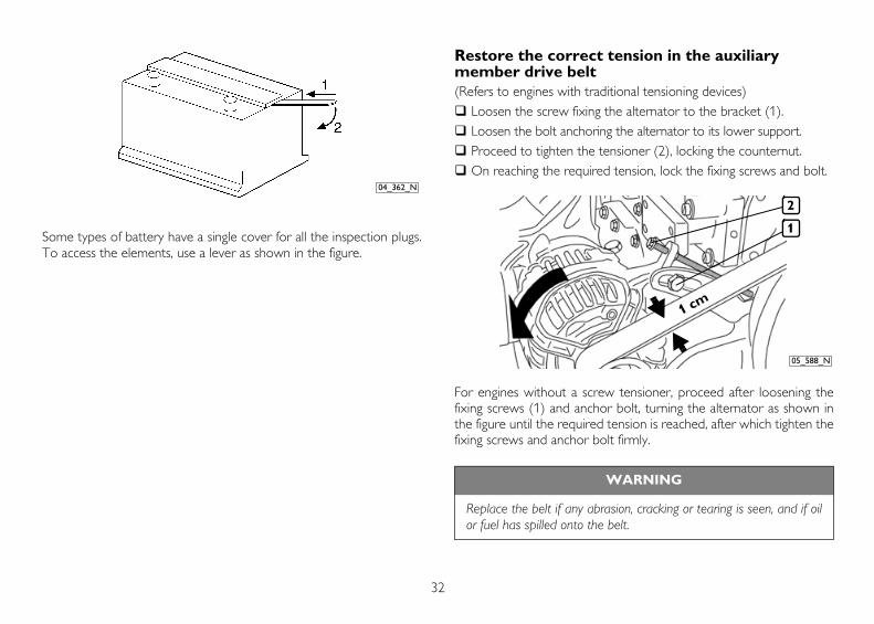
Some types of battery have a single cover for all the inspection plugs.To access the elements, use a lever as shown in the figure.
Restore the correct tension in the auxiliary member drive belt(Refers to engines with traditional tensioning devices)
Loosen the screw fixing the alternator to the bracket (1).Loosen the bolt anchoring the alternator to its lower support.Proceed to tighten the tensioner (2), locking the counternut.On reaching the required tension, lock the fixing screws and bolt.
For engines without a screw tensioner, proceed after loosening thefixing screws (1) and anchor bolt, turning the alternator as shown inthe figure until the required tension is reached, after which tighten thefixing screws and anchor bolt firmly.
04_362_N
WARNING
Replace the belt if any abrasion, cracking or tearing is seen, and if oilor fuel has spilled onto the belt.
05_588_N
2
1
1 cm

33
EN
GL
ISH
Change oilOnly proceed with the engine stopped and at a low temperature, soas to avoid the risk of burning.
Place a container under the drainage plug to collect the used oil(see illustrations in the chapter ENGINE TECHNICAL DATA).
Unscrew the plug and wait until the sump has emptied completely,then fasten the plug in place again.
Fill up through the feeder hole (1) on the timer cover or elsewhere(opt.), using the types and amounts of oil indicated in the tableREFUELLING.
Using the dipstick (2), check that the oil level is between the "Min"and "Max" levels.
Dispose of used oil according to current requirements.
Change oil filterOnly proceed with the engine stopped and at a low temperature, soas to avoid the risk of burning.Only use filters with a filtration level equivalent to the ones you arereplacing (see section FREQUENCY).
Place a container under the filter support (1), to collect the used oil.
Unscrew the filter and remove it (2).
Carefully clean the surfaces of the support that are in contact withthe seal gasket.
Damp the new seal gasket with a thin layer of oil.
Hand screw the new filter into place until the seal gasket touchesthe support, then lock by a further 3/4 of a turn.
Dispose of the old filter according to current requirements.
1
205_583_N
1
2
05_610_N
34
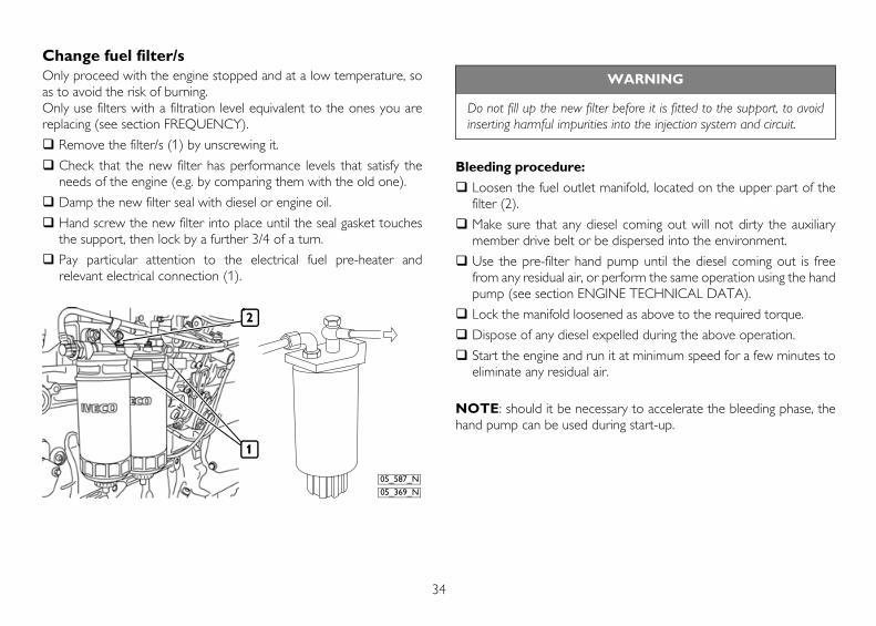
Change fuel filter/sOnly proceed with the engine stopped and at a low temperature, soas to avoid the risk of burning.Only use filters with a filtration level equivalent to the ones you arereplacing (see section FREQUENCY).
Remove the filter/s (1) by unscrewing it.
Check that the new filter has performance levels that satisfy theneeds of the engine (e.g. by comparing them with the old one).
Damp the new filter seal with diesel or engine oil.
Hand screw the new filter into place until the seal gasket touchesthe support, then lock by a further 3/4 of a turn.
Pay particular attention to the electrical fuel pre-heater andrelevant electrical connection (1).
Bleeding procedure:
Loosen the fuel outlet manifold, located on the upper part of thefilter (2).
Make sure that any diesel coming out will not dirty the auxiliarymember drive belt or be dispersed into the environment.
Use the pre-filter hand pump until the diesel coming out is freefrom any residual air, or perform the same operation using the handpump (see section ENGINE TECHNICAL DATA).
Lock the manifold loosened as above to the required torque.
Dispose of any diesel expelled during the above operation.
Start the engine and run it at minimum speed for a few minutes toeliminate any residual air.
NOTE: should it be necessary to accelerate the bleeding phase, thehand pump can be used during start-up.
05_587_N
05_369_N
1
2
WARNING
Do not fill up the new filter before it is fitted to the support, to avoidinserting harmful impurities into the injection system and circuit.

35
EN
GL
ISH
Changing the fuel pre-filterOnly proceed with the engine stopped.
Remove the pre-filter byunscrewing it.
Check that the new filter hasperformance levels that satisfy theneeds of the engine (e.g. bycomparing them with the oldone).
Damp the new filter seal withdiesel or engine oil.
Hand screw the new filter intoplace until the seal gasket touchesthe support, then lock by a further3/4 of a turn.
Loosen the bleeder screw (2) onthe pre-filter support and activatethe hand pump (1) until the supplycircuit is full. Ensure that any fuelcoming out is not dispersed intothe environment.
Lock the bleeder screw tightly.
Start the engine and run it at minimum speed for a few minutes toeliminate any residual air.
NOTE: should it be necessary to accelerate the bleeding phase, thehand pump can be used during start-up.
Check exhaust pipe/s for damageVisually check that the exhaust system is not blocked or damaged.
Make sure that there is no risk of dangerous fumes within themachine. Contact the Manufacturer if necessary.
Change auxiliary member beltPlease refer to the information provided for checking the belt tension.
Change coolantOnly proceed with the engine stopped and at a low temperature, soas to avoid the risk of burning.
Provide suitable containers to ensure that no coolant is dispersedinto the environment.
Loosen the seal elements, remove the sleeves connecting theengine circuit to the heat exchanger and wait until it has emptiedcompletely. When empty, repair the circuit making sure that thesleeves are perfectly sealed.
Fill up the circuit as indicated in the table REFUELLING.
Bleed the circuit and top-up if necessary.
04_361_N
2
1

36
Drain/suck condensation from fuel tankClean the turbochargerCheck the efficiency of the pre-post heating system Adjust play in valves-rocker armsInjector calibrationOverhaul injection pump
MOVING THE ENGINEThe operations necessary to disconnect and subsequently reconnectthe engine must only be carried out by technicians from AuthorisedService Centres.When lifting the engine only, use the U-bolts indicated in this manualin the section ENGINE TECHNICAL DATA and marked on the enginewith special stickers.Lifting must be carried out using a rocker arm that keeps the metalcables supporting the engine parallel, using all the U-bolts providedsimultaneously; the use of a single U-bolt only is not allowed.The engine lifting system must have a capacity and size suited to theweight and dimensions of the engine; check that there is nointerference between the lifting system and the engine components.Do not lift the engine before removing the transmission members thatare coupled to it.
DISPOSAL OF WASTEThe engine is made up of parts and elements that, if discarded, maycause damage to the environment.The materials listed below must be handed over to specialisedCollection Centres; the laws in force in the various Countries foreseesevere penalties for transgressors:
Starter batteries.
Used lubricants.
Mixtures of water and antifreeze.
Filters.
Additional cleaning materials (e.g. greasy or fuel-soaked cloths).
WARNING
The operations listed below must only be carried out by qualified stafffrom the IVECO MOTORS Service Centres or by the Manufacturer'sstaff.The methods used to perform them are described in the Technicaland Repair Manuals.
37
EN
GL
ISH
LONG PERIODS OF INACTIVITY
PREPARING THE ENGINE FOR A LONGPERIOD OF INACTIVITYIn order to prevent oxidation of the internal parts of the engine andof certain components in the injection system, when the engine isexpected to be inoperative for periods of more than two months, thefollowing operations must be carried out in preparation for this:
1. Drain the lubricant from the sump, after first warming up theengine.
2. Fill the engine with protective oil type 30/M (or alternatively oil thatcomplies with MIL 2160B type 2 specifications), up to the"minimum" level indicated on the dipstick. Start the engine and keepit running for approximately 5 minutes.
3. Drain the fuel from the injection circuit, from the filter and from theinjection pump pipes.
4. Connect the fuel circuit to a tank containing CFB (ISO 4113)protective fluid, and feed in the fluid by putting the circuit underpressure and running the engine for approximately 2 minutes, afterfirst disabling the injection system. This operation can be performedby polarising terminal 50 of the starter motor with a positivevoltage equivalent to the rated voltage of the system, using aconductor provided for that purpose.
5. Nebulise approximately 80 g of 30/M protective oil (10 g per litredisplacement) into the turbocharger suction inlet, during thepressurised filling operation described in the previous point.
6. Close all the suction, delivery, ventilation and bleeder openings inthe engine with suitable plugs, or seal them with adhesive tape.
7. Drain the residual 30/M protective oil from the sump. This oil canbe used again for a further 2 preparation operations.
8. Fit signs reading "ENGINE WITHOUT OIL" to the engine and tothe on-board control panel.
9. Drain the coolant, if it has not been mixed with suitable antifreezeand corrosion inhibitors, and affix a sign to indicate the fact.
In the event of prolonged inactivity, the operations described must berepeated every 6 months, following the procedure given below:
A) drain the 30/M protective oil from the sump;
B) repeat the operations described from point 2 to point 7.
Should you intend to protect external parts of the engine, proceed byspraying OVER 19 AR protective liquid on unpainted metal parts, suchas the flywheel, pulleys and the like, avoiding belts, connector cablesand electrical equipment.
38
RESTARTING THE ENGINE AFTER A LONGPERIOD OF INACTIVITY1. Drain the residual 30/M protective oil from the sump.
2. Fill the engine, as prescribed, with lubricant of the type and amountindicated in the table REFUELLING.
3. Drain the CFB protective fluid from the fuel circuit, carrying out thisoperation as indicated under point 3. of PREPARING THEENGINE FOR A LONG PERIOD OF INACTIVITY.
4. Remove the plugs and/or seals from the suction, delivery,ventilation and bleeder openings in the engine, restoring it to anormal state of use. Connect the turbocharger suction inlet to theair filter.
5. Connect the fuel circuits to the machine’s fuel tank, completing theoperations as indicated in point 4. of PREPARING THE ENGINEFOR A LONG PERIOD OF INACTIVITY. During filling operations,connect the fuel return pipe to a collection tank, so as to preventany residual CFB protective fluid from flowing into the machine'sfuel tank.
6. Check the engine and fill it up with coolant as prescribed, bleedingit if necessary.
7. Start the engine and keep it running until the idling speed rate hasstabilised completely.
8. Check that the instruments on the on-board control panel/s areshowing plausible values, and that no alarms are shown.
9. Stop the engine.
10.Remove the "ENGINE WITHOUT OIL" signs from the engine andfrom the on-board control panel.
39
EN
GL
ISH
BEHAVIOUR IN AN EMERGENCY
The user of a machine that has been constructed according to safetyregulations, when following the instructions provided in this manualand the indications given on the engine labels, will be working in safeconditions.Should improper conduct result in accidents, always request theintervention of trained first aid specialists immediately.In an emergency and while awaiting the arrival of first aid specialists,follow the instructions given below.
Engine malfunctionsWhen operating with a malfunctioning engine, take the greatestpossible care when manouevering and make sure that all those aboardare holding firmly to safe hand-holds (see section on ENGINEMALFUNCTIONS)
In case of fireExtinguish the fire using the fire-fighting equipment foreseen, and inthe manner indicated by Fire prevention authorities (fire-fightingequipment for certain machines and equipment is compulsory undercurrent safety legislation).
Burns and scalds1. Extinguish any flames on the burned person's clothing, by:
• throwing water over them;
• using a powder fire-extinguisher, without directing the jet at theperson's face;
• covering with blankets or rolling the victim on the ground.
2. Do not attempt to remove pieces of clothing that may have stuckto the skin;
3. In the case of scalding, immediately but carefully remove anyclothing that may be soaked in the hot liquid;
4. Cover the burn with a special burn dressing or sterile bandage.
Carbon monoxide intoxication (CO)Carbon monoxide from the engine exhaust is without smell, and isdangerous both because it causes intoxication, and because whencombined with air it forms an explosive mixture.In closed rooms, carbon monoxide is extremely dangerous, as it canreach critical concentrations within a very short time.When assisting an intoxicated person in a closed room:
1. Ventilate the room immediately, to reduce the concentration ofgas.
2. When entering the room, hold your breath, do not light flames,lights or ring electric doorbells or phones, to avoid the risk ofexplosion.
3. Carry the intoxicated person out into the fresh air or into a wellventilated room, resting him on one side if he is unconscious.

40
ElectrocutionA. The engine's electrical 12 V or 24 V electrical system does not
involve the risk of electrocution, however, in the event of a short-circuit caused, for example, by a metal tool, there is a risk of burningdue to overheating of the object through which the electricalcurrent runs. In these circumstances:
1. Remove the object that caused the short-circuit, using means thatprovide sufficient heat insulation.
2. Switch off the power at the main switch, if there is one.
B. The electric generator systems (generator units) normally producehigh voltages that are liable to result in extremely dangerouscurrent levels. In the event of medium or high voltage electrocution:
1. Turn off the power supply at the main switch before touching thevictim. If this is not possible, use equipment that is both safe andadequately insulated when touching the victim; remember thattouching a victim of electrocution is also extremely dangerous forthe person giving aid.
2. Proceed as indicated by the competent authorities (cardiacmassage, mouth-to-mouth resuscitation, etc...)
Injuries and fracturesThe vast number of possible circumstances and the specific nature ofoperations required means that the intervention of a medical team isnecessary.
1. In the event of bleeding, keep the edges of the wound pressedtogether until help arrives.
2. If there is any suspicion of a fracture, do not move the injured partand only move the patient if absolutely necessary.
Caustic burnsCaustic skin burns are caused by contact with extremely acid oralkaline substances.For electric maintenance technicians these are typically caused by acidfrom batteries; in these circumstances, proceed as follows:
1. Remove any clothing soaked in the caustic substance.
2. Wash the area with lots of running water, avoiding parts that havenot been burned.
If either battery acid, lubricants or diesel come into contact with theeyes: wash the eyes with water for at least 20 minutes, keeping theeyelids open so that the water flows over the eyeball (move the eyein all directions to wash more thoroughly).

41
EN
GL
ISH
42