use rgu i de - cae healthcare · front matter pn: 905k400652 iii 3. consent to use of collection...
TRANSCRIPT
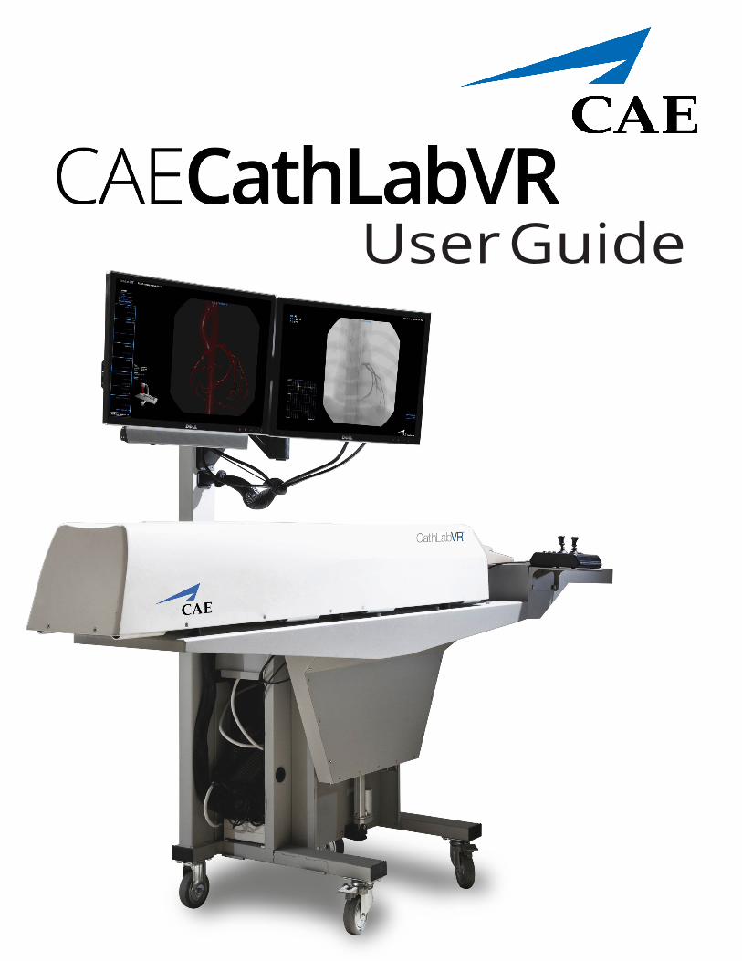
User Guide

Front Matter
END USER LICENSE AGREEMENT FOR CAE PRODUCTSCAREFULLY READ THE FOLLOWING LICENSE. YOU ACCEPT AND AGREE TO BE BOUND BY THIS END USER LICENSE AGREEMENT BY CLICKING THE BUTTON LABELED "ACCEPT" THAT IS DISPLAYED. IF YOU DO NOT AGREE TO THIS END USER LICENSE AGREEMENT, CLICK THE BUTTON LABELED "DECLINE" AND THE SOFTWARE ACCESS WILL BE PROHIBITED.
The software you are about to access is provided to you pursuant to the purchase of the Product by the legal entity which employs you, or which you represent (the “licensee” or “You”), from CAE. This purchase of the Product is subject to CAE’s Healthcare Education Products General Terms and Conditions (the “HEPGTC”) and this End-User License agreement (“Licensee”). The HEPGTC can be found at
1. Interpretations and Definitions
Whenever used in this License, the following terms shall have the meaning set out below:
“Authorized Users” shall mean any person authorized to access the Produce, which shall include the Licensee’s employees, agents, representatives, medical staff and students.
“Confidential Information” means any and all scientific and technical information which is in the possession of, or belonging to, CAE and relating to the Product, including without limitation, all Data, Software, trade secrets, know-how, processes, methodologies, samples, components, analyses, compilations, guides and other information or documents prepared by CAE, its subsidiaries and affiliates and/or their officers, servants, agents, representatives, employees or advisers which contain or are otherwise generated from or reflect any CAE proprietary information, whether or not covered by intellectual property rights or explicitly designated as confidential or proprietary, which is disclosed by any means in written, oral, electronic, or any other form.
“Data” means any documentation or other information provided to Licensee in relation with the Product.
“Product” means any equipment, components, parts, and materials purchased by the Licensee.
“Purpose” means the use of the Software and the Data solely for the operation and maintenance of the Product, and the use of the Product solely as an educational tool.
“Software” means the software, in object code only, embedded in or bundled with the Product or required to operate the Product
“Work” means any images created by the Products which may have the option to be save or reproduced by the Licensee.
iPN: 905K400652

Front Matter CAECathLabVR
2. License
2.1 In consideration of Licensee’s agreement and compliance with the terms and conditions contained in the HEPGTC and in this License, CAE grants to Licensee a personal, non-exclusive, non-transferable license to use the Software and Data exclusively with the Product, and with the device on which this License appears.
2.2 Without limiting the foregoing or any other terms in this License, Licensee shall, and shall ensure that any Authorized Users:
2.3 Except for the License granted herein, CAE grants no express or implied right under any patent, copyright, mask work right, trademark, know how or other intellectual property rights. The Licensee shall not obtain any rights to CAE’s property, or any part thereof, by implication, estoppel or otherwise. Title to and full ownership of any trade secrets and other intellectual property rights related to the Product and components thereof shall remain with CAE and, if applicable, its suppliers. For clarification, Licensee agrees that the source code for the Software is a trade secret of CAE and only CAE shall have the right to alter, maintain, enhance or otherwise modify the Software.
a. not copy (save and except for normal back up and disaster recovery purposes provided such copy shall include CAE’s copyright and any other proprietary notices indicated on the Software and Data), ghost, export or produce any derivative works from the Product, or any part thereof, not network the Product without CAE’s prior written approval, or make it available for concurrent use;
b. not sell, attempt to sell or transfer (unless in compliance with the HEPGTC), sub-license, encumber the Software or Data;
c. not modify the Product in any way, combine with other programs, or reverse engineer, screen scratch, decompile or disassemble any Software nor otherwise attempt to create or derive the source code related thereto;
d. not deface or remove any copyright or proprietary notices;
e. not use the Product without the key, if provided with the Product, or attempt to develop or develop any means or technology which would enable Licensee to bypass the use of the key to operate the Product;
f. prevent anyone other than Authorized Users from accessing or using the Product;
g. not incorporate the Product, in whole or in part, to any product or service that Licensee would make available to a third party, on a commercial basis or not.
2.4 Notwithstanding anything else contained in this License, in no event shall Licensee use the Product and/or Confidential Information to enable, support, or otherwise aid Licensee or a third party to develop any product, software or service competitive with any of CAE’s products.
2.5 CAE reserves the right to embed a software security mechanism within the Product to monitor usage of the Product to verify Licensee’s compliance with this Agreement, as well as to control access to the Software through use of license administration software.
2.6 Licensee hereby recognizes that the entire rights, title and interests in and to Work remain the exclusive property of CAE. Licensee shall not modify such Work in any way whatsoever and shall not remove or alter any CAE notices. However, Licensee is permitted to produce and reproduce such Work only for non-commercial educational purposes.
ii PN: 905K400652

Front Matter
3. Consent to Use of Collection Data and Feedback
3.1 Licensee agrees that CAE may collect and use technical data and related information, times (“Collection Data”), including but not limited to technical information about your Product that is gathered periodically to facilitate the provision of Software updates, Product support and other services related to your Product such as Software feature usage and run times. Such Collected Data shall be anonymous, and shall not personally identify any individual users. In the event that Licensee wishes to opt-out of permitting CAE from having access to Collected Data, Licensee must inform CAE of this requirement..
3.2 Upon the request of CAE, Licensee agrees to provide CAE, from time to time, with comments, suggestions, data, information or feedback (“Feedback”) on the Product.
3.3 Licensee acknowledges and agrees that such Feedback and Collected Data may be freely used by CAE, at its sole discretion, for the design, development, improvement, marketing and commercialization of its products and services, without any restrictions based on confidentiality or intellectual property rights.
4. Term and Termination
4.1 This License shall become effective as of the date of your acceptance of this License and shall remain in effect until terminated as provided hereafter.
4.2 This License terminates immediately upon termination of the HEPGTC.
4.3 CAE may terminate this License immediately, upon written notice, should Licensee (a) attempt to, directly or indirectly, assign or transfer any of the rights granted to it pursuant to this License without CAE’s prior written authorization, (b) disclose, in whole or in part, any Confidential Information, (c) use the Software otherwise than as authorized herein, or (d) is otherwise in breach of its obligations to protect the intellectual property contained in the Product. In addition, should Licensee fail to comply with any other terms and conditions of this Agreement and such failure is not cured within thirty (30) days after receipt of CAE’s written notice, CAE may terminate this Agreement immediately.
4.4 Upon termination of this License, Licensee agrees to immediately discontinue use of the Confidential Information and the Product, and to return same to CAE as well as any copies.
4.5 The following shall survive and continue in full force and effect notwithstanding any termination of this License: the obligations of Licensee under Sections 2 (License), 5 (Non-Disclosure); as well as any other clauses which by their nature and context are intended to survive.
5. Non-Disclosure
5.1 Licensee agrees to keep this License and all Confidential Information obtained hereunder in strict confidence, and shall only disclose same a) to Authorized Users solely for the Purpose and provided such access to the Product conforms, at all times, to the terms and conditions governing the use of the Product contained herein, or b) if required to be disclosed by law, and only to the extent of such disclosure and limited to the purpose requested, with prior notice to CAE to permit it to seek an appropriate remedy to prevent the disclosure, or alternatively to agree to the terms of such disclosure.
iiiPN: 905K400652

Front Matter CAECathLabVR
5.2 The obligations of confidentiality, use and non-disclosure referred to in this Section 5 shall not apply to information which: (i) is or becomes publicly available through no fault of Licensee; (ii) was already in the rightful possession of Licensee prior to its receipt from CAE; (iii) is independently developed by Licensee, provided it is not, in whole or in part, related to the Product; and (iv) is obtained by Licensee in good faith and on a non-confidential basis and without a use restriction from a third party who lawfully obtained and disclosed such information. However, Confidential Information does not come within the foregoing exceptions merely because features of it may be found separately or within a general disclosure in the public domain.5.3 Licensee agrees to be responsible for enforcing the terms of this Section 5 and to take such action, legal or otherwise, to the extent necessary to cause anyone having access to the Confidential Information to comply with the terms and conditions set forth herein (including all actions that Licensee would take to protect its own trade secrets and confidential information but with not less than reasonable care). Licensee shall be responsible and indemnify, defend and hold harmless CAE for any default caused by any such persons.
6. Irreparable Harm
6.1 Licensee acknowledges that the Software and Data constitute a special, irreplaceable asset of great value to CAE, and that a breach, in any way, of any of Licensee’s obligations under Sections 2 (License), and 5 (Non-Disclosure) hereof would cause serious and irreparable harm to CAE which may not be adequately compensated for in damages. If the Licensee breaches any of such provisions, Licensee consents to an injunction being issued against it restraining it from any further breach of such provision, without derogation from any other remedy which CAE may have in the event of such a breach.
7. Warranty
7.1 THE SOLE WARRANTIES PROVIDED BY CAE ARE LIMITED TO THE WARRANTIES PROVIDED IN THE HEPGTC. ANY WARRANTIES PROVIDED ARE PERSONAL AND NOT TRANSFERABLE.
8. Limitation of Liability
8.1 CAE’S LIABILITY SHALL IN NO CIRCUMSTANCES EXCEED THE LIMITATION OF LIABILITY INDICATED IN THE HEPGTC.
8.2 IN NO EVENT WILL CAE BE LIABLE FOR ANY LOSS OF USE, LOSS OF PROFIT, INTERRUPTION OF BUSINESS, OR ANY INDIRECT, SPECIAL, INCIDENTAL, PUNITIVE OR CONSEQUENTIAL DAMAGES OF ANY KIND (INCLUDING LOST PROFITS), REGARDLESS OF THE FORM OF ACTION, WHETHER IN CONTRACT, TORT (INCLUDING NEGLIGENCE), STRICT PRODUCT LIABILITY, OR OTHERWISE, EVEN IF CAE HAS BEEN ADVISED OR SHOULD HAVE BEEN AWARE OF THE POSSIBILITY OF SUCH DAMAGES. IN NO EVENT WILL CAE’S LIABILITY TO LICENSEE FOR ANY CLAIM, WHETHER IN CONTRACT, TORT OR ANY OTHER THEORY OF LIABILITY, EXCEED THE PURCHASE PRICE OF THE PRODUCT PAID BY LICENSEE.
iv PN: 905K400652

Front Matter
9. Third-Party Software
9.1 The Software may come bundled or otherwise be distributed with open source or other third party software, which is subject to the terms and conditions of the specific license under which it is distributed. OPEN SOURCE SOFTWARE IS PROVIDED BY CAE "AS IS" WITHOUT ANY WARRANTY, EXPRESS, IMPLIED, OR OTHERWISE, INCLUDING BUT NOT LIMITED TO THE IMPLIED WARRANTY OF MERCHANTABILITY, FITNESS FOR A PARTICULAR PURPOSE AND NON-INFRINGEMENT. NOTWITHSTANDING ANYTHING TO THE CONTRARY IN THIS EULA, AS IT RELATES TO ANY AND ALL CLAIMS ARISING OUT OF OR IN CONNECTION WITH OPEN SOURCE SOFTWARE, DELL SHALL HAVE NO LIABILITY FOR ANY DIRECT, INDIRECT, INCIDENTAL, PUNITIVE, SPECIAL OR CONSEQUENTIAL DAMAGES, HOWEVER CAUSED AND ON ANY THEORY OF LIABILITY, WHETHER IN CONTRACT, STRICT LIABILITY, OR TORT (INCLUDING NEGLIGENCE OR OTHERWISE) ARISING IN ANY WAY OUT OF THE USE OF OPEN SOURCE SOFTWARE, EVEN IF ADVISED OF THE POSSIBILITY OF SUCH DAMAGES.
10. Administrative Positions
10.1 Applicable Law and Jurisdiction: This License shall be governed by, subject to, and interpreted according to the laws of the State of Florida, U. S. A., without regard to its conflict of law rules. In all cases, the Parties expressly exclude and waive the application of the United Nations Convention on Commercial Agreements for the International Sale of Goods (1980) (Vienna Sales Convention) as amended. The exclusive jurisdiction for the resolution of any and all disputes arising out of or in connection with this Agreement shall be a court of appropriate jurisdiction located in the State of Florida, U.S.A. Each Party hereby waives any right that it might otherwise have to object to such venue or seek dismissal of the action on the basis of forum non-conveniens. EACH PARTY HERETO IRREVOCABLY WAIVES, TO THE FULLEST EXTENT PERMITTED BY APPLICABLE LAW, ANY AND ALL RIGHT TO TRIAL BY JURY IN ANY LEGAL PROCEEDING ARISING OUT OF OR RELATING TO THIS LICENSE. Notwithstanding the foregoing, if a party seeks injunctive proceedings to preserve confidentiality obligations or intellectual property rights, then it is entitled to seek relief before the competent court/body of any jurisdiction.
10.2 United States Government Licensee: If Licensee is the United States Government (“U.S. Government”) or a unit or agency of the U.S. Government, the Software and Data are deemed to be “commercial computer software” and “commercial computer software documentation”, respectively, pursuant to DFAR Section 227.7202 and FAR Section 12.212 b) as applicable. Any use, modification, reproduction, release, performance, display, or disclosure of the Software and/or Data by the U. S. Government, or any of its units or agencies shall be governed solely by the terms of this License and the HEPGTC. Any technical data provided by CAE with the Product that is not covered by the above provisions is deemed to be "technical data-commercial items" pursuant to DFAR Section 252.227.7015(a).
10.3 Export Controls: Licensee acknowledges that the laws and regulations of the United States may restrict the export and re-export of commodities and technical data of United States origin, including the Software. Licensee agrees that it will not export or re-export Software of, or containing items of, United States origin, in any form, without the appropriate United States and foreign governmental licenses.
vPN: 905K400652
Front Matter CAECathLabVR
10.4 Excluded Data: Licensee acknowledges that Software provided under this License are not designed with security and access management for the processing and/or storage of the following categories of data: (1) data that is classified and or used on the U.S. Munitions list, including software and technical data; (2) articles, services and related technical data designated as defense articles and defense services; (3) ITAR (International Traffic in Arms Regulations) related data; and (4) other personally identifiable information that is subject to heightened security requirements as a result of Licensee's internal policies or practices or by law (collectively referred to as “Excluded Data”). Licensee hereby agrees that Licensee is solely responsible for reviewing its data that will be provided to CAE (or to which CAE will have access) to ensure that it does not contain Excluded Data.10.5 No Waiver: No omission or delay by either party at any time to enforce a right or remedy reserved to it or to require performance of any of the terms of this License at the times designated, shall be a waiver of such right or remedy to which the party is entitled, nor shall it in any way affect the right of the party to subsequently enforce such provisions.
10.6 Modification: No provision of this License shall be deemed waived, amended or modified by either party unless the waiver, amendment or modification is in writing and signed by each of the parties to this License.
10.7 Severity: If any one or more of the provisions of this License is for any reason held invalid, illegal or unenforceable, the remaining provisions of this Agreement will be unimpaired.
End of End User License Agreement
vi PN: 905K400652
Front Matter
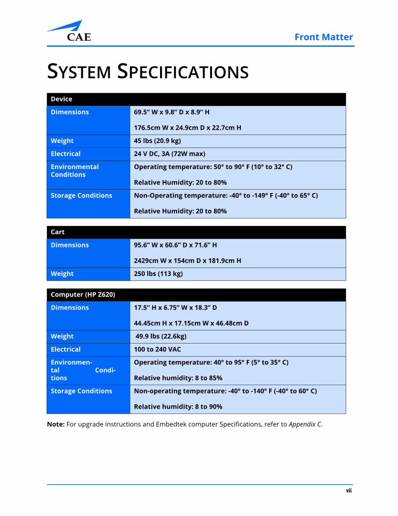
SYSTEM SPECIFICATIONS
Note: For upgrade instructions and Embedtek computer Specifications, refer to Appendix C.
Device
Dimensions 69.5” W x 9.8” D x 8.9” H
176.5cm W x 24.9cm D x 22.7cm H
Weight 45 lbs (20.9 kg)
Electrical 24 V DC, 3A (72W max)
Environmental Conditions
Operating temperature: 50° to 90° F (10° to 32° C)
Relative Humidity: 20 to 80%
Storage Conditions Non-Operating temperature: -40° to -149° F (-40° to 65° C)
Relative Humidity: 20 to 80%
Cart
Dimensions 95.6” W x 60.6” D x 71.6” H
2429cm W x 154cm D x 181.9cm H
Weight 250 lbs (113 kg)
Computer (HP Z620)
Dimensions 17.5” H x 6.75” W x 18.3” D
44.45cm H x 17.15cm W x 46.48cm D
Weight 49.9 lbs (22.6kg)
Electrical 100 to 240 VAC
Environmen-tal Condi-tions
Operating temperature: 40° to 95° F (5° to 35° C)
Relative humidity: 8 to 85%
Storage Conditions Non-operating temperature: -40° to -140° F (-40° to 60° C)
Relative humidity: 8 to 90%
vii

Front Matter CAECathLabVR
CAUTIONS AND WARNINGSPlease read and understand these cautions and warnings before you begin using the simulator.
• Keep all electronic equipment free from high humidity or liquids
• Avoid weighing down the equipment with any tools or accessories not relevant to the immediately exercise
• Do not operate your equipment with any covers removed
• Do not use your equipment in a wet environment. Protect equipment for liquid intrusion
• Do not put any object on top of the bottom platform. Movement of the lift mechanism can cause crush hazard, resulting in possible bodily injuries and damaged equipment.
• Do not jam the motor lift mechanism onto an object. This is a misuse and subjects the motor to burn out. It can also result in possible bodily injuries and damaged equipment.
• Tip-over hazard: Do not move your equipment without fully lowering the lift mechanism. Failure to do so can result in possible bodily injury and damaged equipment.
• Improper or prolonged keyboard use may results in injury
• Viewing a monitor screen for extended period of time may result in eye strain
• Ensure that the equipment relies on circuit protection in the building supple
• Install equipment near an electric socket. Ensure cables do not represent a hazard
viii

Table of Contents
End User License Agreement For CAE Products .................................... i
System Specifications ............................................................................. vii
Cautions and Warnings ......................................................................... viii
Introduction............................................................................................... 1Contained in this User Guide .......................................................................2
Equipment Overview ................................................................................ 3CathLabVR Simulator ....................................................................................4
Anatomy Plate................................................................................................4
CathLabVR Computer....................................................................................4
CathLabVR Cart ..............................................................................................5
Monitor Pole...................................................................................................5
Extension Tray................................................................................................5
CathLabVR Shelf.............................................................................................5
Control Box.....................................................................................................5
Keyboard and Mouse....................................................................................5
Monitors .........................................................................................................6
Monitor Power Cable ....................................................................................6
Monitor DVI Cables........................................................................................6
Foot Pedals .....................................................................................................6
Accessories .....................................................................................................6
Embolic Protection Tool Kit ..........................................................................7
CRDM Tool Kit ................................................................................................7
Vascular Tool Kit .......................................................................................8
Before Using the Simulator ..........................................................................8
Using the Simulator .................................................................................. 9Starting the Software ..................................................................................10
Interface Overview.................................................................................12
Selecting a Simulation.................................................................................15
Reviewing the Didactic Content............................................................18
Training Objectives......................................................................................19
Running a Simulation..................................................................................24
1

Table of Contents
Using the Simulation Tips .....................................................................27
Selecting a Tool ......................................................................................28
Inserting a Tool.......................................................................................30
Removing a Tool.....................................................................................32
Using the Pedals.....................................................................................33
Calibrating the Measurement Feature ................................................35
Using the Control Box............................................................................36
Using the Contrast Syringe ...................................................................37
Using the Physio Feature ......................................................................39
Using the Roadmapping Feature .........................................................40
Customizing a Wire or Stylet.................................................................41
Fixating an Active-Fixation Lead...........................................................43
Using the Venogram Balloon................................................................44
Using the Balloon Inflation Feature .....................................................45
Using the Embolic Protection Devices.................................................47
Using the Adjunct Therapy Feature .....................................................48
Using the Analyzer Function .................................................................49
Accessing the Cine Gallery ....................................................................50
Accessing the Stills Gallery....................................................................51
Ending a Simulation.....................................................................................51
Viewing Results ............................................................................................52
Viewing Personal Data...........................................................................53
Viewing Usage Summaries .........................................................................54
Viewing Reports ...........................................................................................55
Printing Data from the Simulator ..............................................................58
Printing Data to a Network Printer ......................................................58
Printing Data to a PDF File ....................................................................60
Modifying Language Preferences ..............................................................62
Adjusting the Volume..................................................................................63
Hiding the Available Tasks Panel ...............................................................63
Exiting the Software ....................................................................................64
Frequently Asked Questions..................................................................65
2

Table of Contents
Software Questions.....................................................................................65
Module Instruments and Required Equipment.......................................72
Cardiac Rhythm Disease Management (CRDM) .................................72
Cardiac Surgery ......................................................................................72
Percutaneous Coronary Interventions (PCI) .......................................73
Percutaneous Peripheral Interventions (PPI) .....................................74
Appendix B - Keyboard Shortcuts .........................................................75
Introduction.............................................................................................76Contained in this User Guide .....................................................................77
Appendix C - ............................................................................................79
Upgrade Instructions and Embedtek Computer Specifications........79Medtronic CathLab VR™ Upgrade instructions........................................79
3

Table of Contents
4

Introduction
INTRODUCTIONThis CathLabVRTM Simulator User Guide provides information about setting up the simulator, navigating the user interface, and maintaining the system.
The CathLabVR System allows physicians, nurses and technicians to practice endovascular diagnostic and intervention procedures in a highly realistic, reproducible and safe training environment. Trainees can navigate realistically modified endovascular tools through a virtual anatomy based on actual patient data. 3-D graphics, auditory and state-of-the-art haptic feedback enhance the virtual reality.
IMPORTANT: The CathLabVR Simulator is a training tool. The simulator is not intended to diagnose the condition of a live human being or identify a life-threatening situation. The CathVR Simulator is one of a series of didactic tools that can be used to improve training for endovascular diagnostic and intervention procedures. This simulator is not intended to replace any courses or hands-on sessions with live subjects, but should be implemented as part of a blended learning solution.
The CathLabVR Simulator
1PN: 905K400652

Introduction CAECathLabVR
Contained in this User GuideThis User Guide has been designed for quick access to information on how to use and maintain the CathLabVR Simulator. Please be sure to read and follow the Cautions and Warnings on the pages preceding the Table of Contents. This is for the safety of users as well as for the protection of the simulator.
The Equipment Overview outlines the items that come standard with the purchase of a CathLabVR base unit.
The Using the Simulator section provides instructions on the use of the various tools and hardware features integrated into the simulated experience. This section also includes information on how the simulator and software components work and the functionality that each supports. Various surgical procedures are explained, along with how these procedures isolate critically important learning objectives.
The Frequently Asked Questions section addresses some of the more common troubleshooting concerns.
The Module Descriptions appendix outlines the specific tools and accessories that should be used in each of the procedures for the CathLabVR.
The Keyboard Shortcuts appendix describes the shortcut keys and their functions for the CathLabVR.
2 PN: 905K400652

Equipment Overview
EQUIPMENT OVERVIEWThe CathLabVRTM Simulator comes standard with the necessary equipment and accessories for using the base unit.
Note: As you would with any shipment, check the inventory against the packing invoice to verify that all components have been received.
Standard Equipment
CathLabVR Simulator
Anatomy Plate
CathLabVR Computer
CathLabVR Cart
Monitor Pole
Extension Tray
Shelf
Control Box
Keyboard and Mouse
Monitors (2)
Monitor Power Cable
DVI Monitor Cables (2)
Dual Foot Pedals
Accessories
3PN: 905K400652
Equipment Overview CAECathLabVR
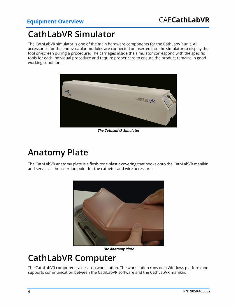
CathLabVR SimulatorThe CathLabVR simulator is one of the main hardware components for the CathLabVR unit. All accessories for the endovascular modules are connected or inserted into the simulator to display the tool on-screen during a procedure. The carriages inside the simulator correspond with the specific tools for each individual procedure and require proper care to ensure the product remains in good working condition.
The CathLabVR Simulator
Anatomy PlateThe CathLabVR anatomy plate is a flesh-tone plastic covering that hooks onto the CathLabVR manikin and serves as the insertion point for the catheter and wire accessories.
The Anatomy Plate
CathLabVR ComputerThe CathLabVR computer is a desktop workstation. The workstation runs on a Windows platform and supports communication between the CathLabVR software and the CathLabVR manikin.
4 PN: 905K400652
Equipment Overview
CathLabVR CartThe CathLabVR cart is the structure upon which the CathLabVR manikin, computer and shelves is secured. The monitor pole is attached to the back of the cart and the computer is stored inside the cart. The manikin, shelf and trays attach to the top of the cart.
Monitor PoleThe monitor pole attaches to the cart structure and contains a monitor arm for mounting the two flat screen monitors.
Extension TrayThe extension tray attaches to the main cart structure and serves as a resting place for accessories prior to use or insertion.
CathLabVR ShelfThe CathLabVR contains a shelf upon which the Control Box is placed.
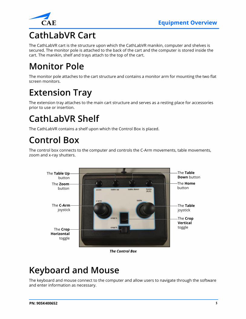
Control BoxThe control box connects to the computer and controls the C-Arm movements, table movements, zoom and x-ray shutters.
The Control Box
Keyboard and MouseThe keyboard and mouse connect to the computer and allow users to navigate through the software and enter information as necessary.
The Zoombutton
The C-Armjoystick
The CropHorizontal
toggle
The Home button
The Table joystick
The Crop Vertical toggle
The Table Upbutton
The Table Down button
5PN: 905K400652

Equipment Overview CAECathLabVR
MonitorsThe CathLabVR comes standard with two flat screen monitors. This dual monitor setup allows users to view their progress and different functions during the simulation with efficiency and accuracy.
Monitor Power CableThe CathLabVR contains one monitor power cable with two female receptors, each connecting to a separate monitor.
Monitor DVI CablesThe CathLabVR includes two monitor DVI cables which connect the monitors to the computer.
Foot PedalsThe dual foot pedals connect directly to the back of the manikin and serve as a necessary tool for completing most simulations on the CathLabVR. The Cine (pronounced “sin-nee”) pedal captures video clips of actions being performed during a procedure. The Fluro pedal controls the distribution of x-ray from the C-Arm during a procedure.
Note: In all procedures of the CRDM module, the Fluoro feature is activated by the RIGHT pedal and the Cine feature is activated by the LEFT pedal.
The Foot Pedals
AccessoriesThe CathLabVR base unit comes with three tool kits of accessories: the Embolic Protection Tool Kit, Vascular Tool Kit and the CRDM Tool Kit. The accessories are provided for use in the different learning modules.
6 PN: 905K400652

Equipment Overview
Embolic Protection Tool KitThe Embolic Protection Tool Kit contains the following accessories:
• Filter Basket EPD Handle
• Occlusive Ballon EPD Handle
• Self-expanding Stent Handle
• 0.014” Guardwire wire
• Embolectomy aspiration catheter
• Syringe
CRDM Tool KitThe CRDM Tool Kit contains the following accessories:
• Accessory handles for deflectable catheters (2)
• Guidewire steering handle (torque tool)
• Deflectable (guide) catheters
• 0.035” Diagnostic guidewire
• 0.016” Nitinol guidewire
• Cook introducer valve
• Left heart module, hybrid lead 2187
• 0.016” gray stylet
• Left heart module hyrbid lead 4193
• 55cm Attain (green) catheter
• Modified Attain 6215 venogram balloon catheter
• Venogram balloon syringe
• Inner deflectable catheter
• Left heart module, hybrid lead 4194
• Attain II (outer and inner) subselecting catheters
7PN: 905K400652
Equipment Overview CAECathLabVR
Vascular Tool KitThe vascular tool kit contains the following accessories:
• Guidwire steering handle
• 30 ATM inflation device
• Diagnostic catheter
• Guide catheter
• Modified OTW therapeutic catheter
• Modified RX therapeutic catheter
• .035” diagnostic guidewire
• .035” stiff guidewire
• .016” guidewire
• .14” interventional guidewire
• Modified MX2 therapeutic catheter
• Contrast syringe
Before Using the SimulatorProper operation of the CathLabVR simulation requires correct configuration. Before setting up the system, keep in mind these basic guidelines:
• Read and understand the Cautions and Warnings in the beginning of this User Guide
• Do not power on any components until instructed in the text
• Do not install any Windows updates or anti-virus software when connecting to the network
8 PN: 905K400652

Using the Simulator
USING THE SIMULATORNote: For optimal use, no other software programs should be open while the simulator software is running.
Note: To use the printing functions in the software, a network connection must be established. For further assistance, contact your system administrator.
9PN: 905K400652

Using the Simulator CAECathLabVR
Starting the SoftwareOnce the CathLabVR simulator is powered on, the software launches automatically and the Login screen appears.
The Login Screen
To log in to the software:
1. Enter the assigned username in the Username field. To log in as a guest, enter guest.
Note: Any tasks performed while using the guest login will be recorded in the guest account only if the administrator selected Data Recorded in the guest personal data screen.
2. Enter the assigned password in the Password field. To log in as a guest, enter guest.
3. Click Login
The Usernamefield
The Password field
The Login button
10 PN: 905K400652

Using the Simulator
The CathLabVR Home screen appears.
The Home Screen
From the Home screen, users can select and start a simulation exercise, view personal data and print usage summaries and reports. Users are also able to modify language preferences and access the user guide from the Home screen.
11PN: 905K400652

Using the Simulator CAECathLabVR
Interface OverviewThe CathLabVR user interface contains a dashboard of icons that represent the tools available to users.
The Icon Dashboard
When an icon is selected, the icon will appear blue and the associated content will appear in the main screen on the interface. The left panel contains is a list of options for users.
The My Tasks icon is selected by default and referred to as the Home screen when users first login to the software.
The Home Screen
The My Tasksicon
The My Profileicon
The Usageicon
The Reportsicon
The main screen
The AvailableTasks panel
12 PN: 905K400652

Using the Simulator
My TasksFrom the My Tasks screen, users can choose a simulation, review didactic content, run a simulation and review results.
The My Tasks Screen
My ProfileFrom the My Profile screen, users can review their personal data including username, registration and contact information and privileges.
The My Profile Screen
The My Tasksicon
The My Profileicon
13PN: 905K400652
Using the Simulator CAECathLabVR
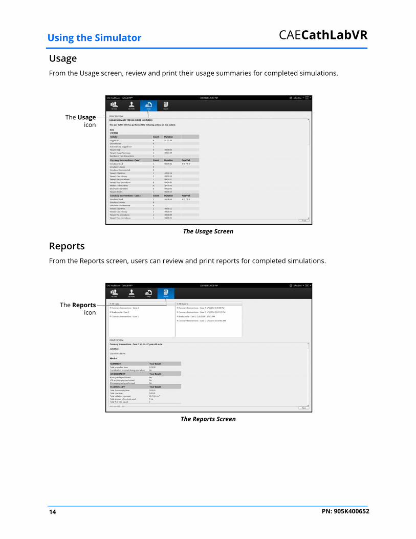
UsageFrom the Usage screen, review and print their usage summaries for completed simulations.
The Usage Screen
ReportsFrom the Reports screen, users can review and print reports for completed simulations.
The Reports Screen
The Usageicon
The Reportsicon
14 PN: 905K400652

Using the Simulator
Selecting a SimulationEach module in the software contains a specially-developed curriculum to test learners on their ability to perform acute endovacular procedures. Based on the courses and tasks assigned to the learner by the administrator, the training experience is customized to help the learner meet the necessary educational objectives.
Note: Learners only have access to the curriculum assigned to them by the administrator.
To select a simulation:
1. Ensure the My Tasks icon is selected and the Home screen is displayed
The Home Screen
Note: When selected, the icon on the dashboard is highlighted blue.
The Icon Dashboard
15PN: 905K400652

Using the Simulator CAECathLabVR
2. From the Available Tasks panel on the left side of the screen, click the desired moduleThe Home Screen
3. Click the desired course
The Home Screen
The desiredmodule
The desiredcourse
16 PN: 905K400652
Using the Simulator
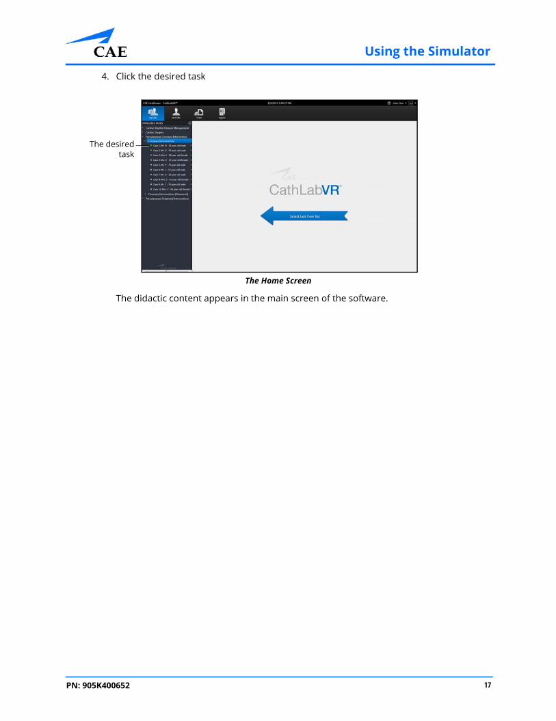
4. Click the desired task
The Home Screen
The didactic content appears in the main screen of the software.
The desiredtask
17PN: 905K400652

Using the Simulator CAECathLabVR
Reviewing the Didactic ContentBefore beginning a simulation, users should review the didactic content for the selected procedure. The didactic content contains information users need to know before and after performing a specific procedure.
The didactic content for tasks may include Training Objectives, Case History, Pre-Procedures, Post-Procedures, and Collaborators. The Results screen is only accessible after a task is completed. The content included in each module varies depending on the procedure.
Didactic Content Screen for Percutaneous Coronary Interventions
Note: Parameters can only be changed for specific tasks when the user parameters are unlocked by an administrator.
18 PN: 905K400652

Using the Simulator
Training ObjectivesTo access the Training Objectives screen, click the Training Objectives tab. When selected, the tab appears blue and the Training Objectives screen appears.
The Training Objectives Screen
The Training Objectives screen outlines the training goals and objectives users meet upon successful completion of the procedure.
TheTraining
Objectivestab
19PN: 905K400652
Using the Simulator CAECathLabVR
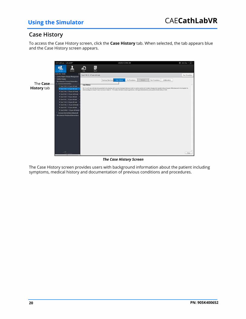
Case HistoryTo access the Case History screen, click the Case History tab. When selected, the tab appears blue and the Case History screen appears.
The Case History Screen
The Case History screen provides users with background information about the patient including symptoms, medical history and documentation of previous conditions and procedures.
The CaseHistory tab
20 PN: 905K400652
Using the Simulator
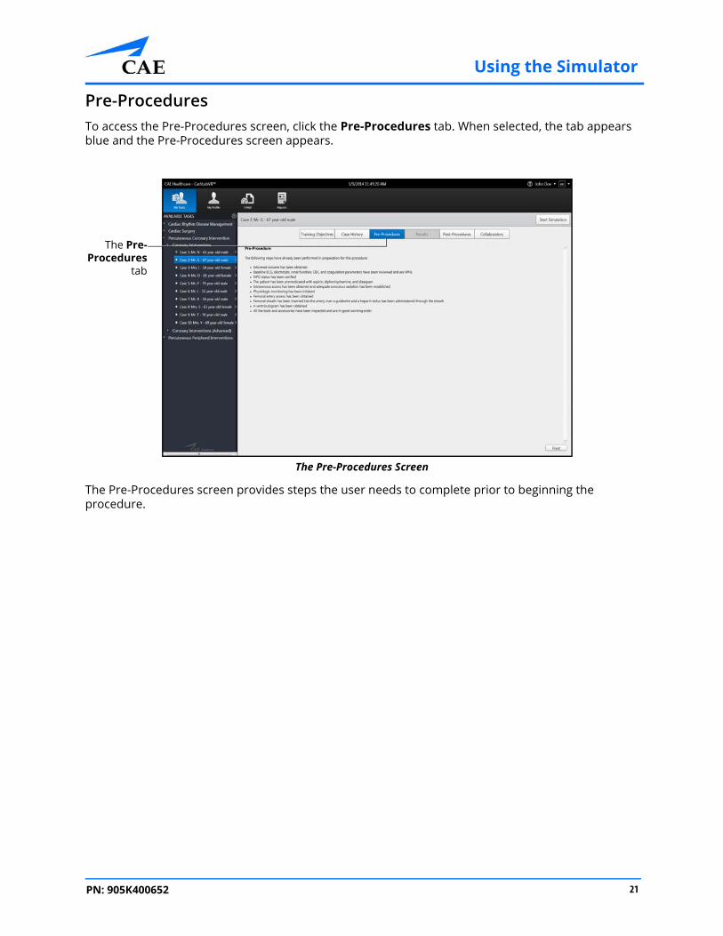
Pre-ProceduresTo access the Pre-Procedures screen, click the Pre-Procedures tab. When selected, the tab appears blue and the Pre-Procedures screen appears.
The Pre-Procedures Screen
The Pre-Procedures screen provides steps the user needs to complete prior to beginning the procedure.
The Pre-Procedures
tab
21PN: 905K400652

Using the Simulator CAECathLabVR
Post-ProceduresTo access the Post-Procedures screen, click the Post-Procedures tab. When selected, the tab appears blue and the Post-Procedures screen appears.
The Post-Procedures Screen
The Post-Procedures screen provides actions users should perform after the procedure is complete.
The Post-Procedures tab
22 PN: 905K400652

Using the Simulator
CollaboratorsTo access the Collaborators screen, click the Collaborators tab. When selected, the tab appears blue and the Collaborators screen appears.
The Collaborators Screen
The Collaborators screen credits the individuals and institutions who contributed to the development of the module task.
23PN: 905K400652

Using the Simulator CAECathLabVR
Running a SimulationPrior to running a simulation, prepare for the simulation by completing the following steps:
1. Select the desired task
2. Review the associated didactic content
After the preparation steps are complete, start the simulation.
To start a simulation:
1. Click the Start Simulation button from any screen within the selected task
The Case History Screen
The Start Simulation button
24 PN: 905K400652

Using the Simulator
The simulation launches and the initialization screen appears.
The Initialization Screen
Once the initialization is complete, the simulation start screen appears.
The right monitor displays the Fluoro imaging, vital signs and ECG for the simulated patient.
The Simulation Start Screen -Right Monitor
25PN: 905K400652

Using the Simulator CAECathLabVR
The left monitor displays the tool selection panel, C-Arm glyph and coordinates, and the feature options list: Physio, Cine, Still and Case History.The Simulation Start Screen - Left Monitor
Note: Be sure to observe the content on both monitors while performing procedures.
When learners choose a feature from the features list, the content populates the left monitor.
The featureoptions list
The toolselection
panel
The C-Armglyph
The C-Armcoordinates
26 PN: 905K400652

Using the Simulator
Using the Simulation TipsThe simulation tips feature guides the learner through a procedure with tips for completing the next required action during a running simulation. The simulation tips are present by default.
The simulation tips appear in the bottom-left corner of the left monitor.
The Simulation Screen - Simulation Tips On
To turn off the simulation tips, click the Simulation Tips feature. The simulation tips off message appears.
The Simulation Screen - Simulation Tips Off
TheSimulation
Tips feature
The Simulation Tips message
TheSimulation
Tips feature
The Simulation Tips message
27PN: 905K400652
Using the Simulator CAECathLabVR
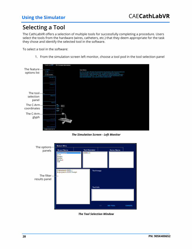
Selecting a ToolThe CathLabVR offers a selection of multiple tools for successfully completing a procedure. Users select the tools from the hardware (wires, catheters, etc.) that they deem appropriate for the task they chose and identify the selected tool in the software.
To select a tool in the software:
1. From the simulation screen left monitor, choose a tool pod in the tool selection panel
The Simulation Screen - Left Monitor
The Tool Selection Window
The featureoptions list
The toolselection
panel
The C-Armglyph
The C-Armcoordinates
The optionspanels
The filterresults panel
28 PN: 905K400652

Using the Simulator
2. Select different options from the options panel to narrow the tool options in the filter results panel
The Tool Selection Window
Users can also select a tool directly from the filter results panel without selecting different options.
3. Click OK to select the tool
The Simulation Screen - Guidewire Selected
The physical tool can now be inserted into the simulator.
The optionspanels
The filterresults panel
The OK button
The selectedguidewire
The toolselection
panel
29PN: 905K400652

Using the Simulator CAECathLabVR
Inserting a ToolGuide wires and catheters are the selected tools that can be physically inserted inside the simulator.
Note: Prior to inserting a tool into the simulator, select the tool in the software using the tool selection panel.
To insert a tool in the simulator:
1. Align the tool with the hole and gently feed the tool into the hole
The Tool Insertion
The Smart Capture feature initiates on screen.
Note: The Smart Capture feature appears on the right monitor.
2. Depress the Fluoro foot pedal to activate the x-ray feature
3. Continue to slowly insert the tool until all four lights on the Smart Capture feature turn green
The cathetertool
The simulator
30 PN: 905K400652

Using the Simulator
This indicates that the simulator has engaged the tool properly.
The Simulation Screen
4. Activate the Fluoro feature intermittently to view the path of the tool and navigate appropriately
To manipulate the tool, twist the end of the tool slowly until the to ensure no damage or perforation occurs.
Note: If the inserted tool conflicts with any of the previous selected tools, the Tool Diameter Discrepancy message will appear. To select the inserted tool, from the Tool Selection panel, deselect the conflicting tool and choose the inserted tool.
The SmartCapture
lights
31PN: 905K400652

Using the Simulator CAECathLabVR
Removing a ToolTo remove a tool form the simulator:
1. From the simulation screen left monitor, choose a tool pod in the tool selection panel
The Simulation Screen - Guidewire Selected
The Tool Selection Window
2. Click NO TOOL to deselect the tool
The selectedguidewire
The toolselection
panel
The optionspanels
The filterresults panel
The NO TOOL button
32 PN: 905K400652

Using the Simulator
The Simulation Screen - Left Monitor
The physical tool can now be removed into the simulator.
Using the PedalsThe dual foot pedals are used to control the x-ray and video capture tools.
The Foot Pedals
The featureoptions list
The toolselection
panel
The C-Armglyph
The C-Armcoordinates
33PN: 905K400652

Using the Simulator CAECathLabVR
Activating the Fluoro FeatureTo activate the Fluoro (x-ray) feature, depress the Fluoro pedal. Upon starting a simulation, the right monitor will prompt the learner to press the pedal and activate the Fluoro feature to view the x-ray.
The Fluoro Activation Message
Note: In all procedures of the CRDM module, press down on the RIGHT pedal (labeled Cine) to use the Fluoro feature.
Activating the Cine FeatureTo capture a video of the procedure, depress the Cine pedal and hold for desired length of recording.
Once the pedal is released, the Cine review screen appears.
On the Cine review screen, the selected recording will display in a loop on the Left monitor until another feature from the features list is selected.
The Simulation Screen - Cine Feature
Note: In all procedures of the CRDM module, depress the LEFT pedal (labeled Fluoro) to use the Cine feature.
34 PN: 905K400652

Using the Simulator
Calibrating the Measurement FeatureQCA (Quantitative Cine Angiometrics) allows the user to record a Cine Angiogram, pause the Cine and make detailed measurements from the still image. Prior to any measurements, the user should calibrate so that measurements are accurate in the chosen angle and zoom magnification.
QCA calibration should be performed prior to obtaining any measurements from a Still cine image. It is best to select a catheter or tool with a known dimension, (such as the diameter of the guide catheter), and use this to calibrate the QCA measurement.
To calibrate a measurement:
1. Record a cine image
2. Pause the cine loop to obtain a “still” image
3. Right-click on one side of the catheter and right-click again on the opposite side of the catheter
A blue line appears, representing the diameter of the catheter.
4. From the Cine feature options, select Calibrate
The QCA dialog box will prompt the user to input the desired measurement, (the known diameter of the catheter, in millimeters).
5. Once this valued is entered, any new measurements will be correct in the current view and magnification
Note: If the anatomy is viewed in a new Fluoro angle, or a different Zoom magnification, the QCA measurements should be re-calibrated in the new view prior to any new measurements.
35PN: 905K400652
Using the Simulator CAECathLabVR
Using the Control BoxThe control box allows users to adjust different C-Arm and Table settings.
The Control Box
• Push the Zoom button to zoom in on an x-ray image
• Push the Table Up button to raise the height of the table in the c-arm glyph
• Push the Table Down button to lower the height of the table in the c-arm glyph
• Push the Home button to return the C-arm and table to the home position
• Use the Crop V toggle switch to widen or narrow the shutter opening with respect to the cranial/caudal axis
• Use the Crop H toggle switch to widen or narrow the shutter opening with respect to the left/right axis
• Use the Table joystick to rotate the table position
• Use the C-Arm joystick to rotate the c-arm position
The crop vertical toggle switch
The crop horizontal toggle switch
The table joystick
The c-armjoystick
The zoombutton
The home button
The table down buttonThe table up button
36 PN: 905K400652

Using the Simulator
Using the Contrast SyringeThe contrast syringe accessory tool allows learners to see a vascular structure more clearly on the x-ray by injecting contrast dye into the vessels.
To use the contrast syringe:
1. Ensure the contrast syringe is connected to the back of the simulator
The Accessory Ports
2. Pull back on the syringe
3. Press the Fluoro pedal to activate the x-ray feature and show a live x-ray of the anatomy
4. Push the contrast syringe to “inject” the contrast dye
The contrast syringe port
37PN: 905K400652

Using the Simulator CAECathLabVR
The contrast dye pulses through the vessels on the x-ray.The Fluoro Image with Contrast Dye - Right Monitor
Note: The Cine feature can be activated in place of the Fluoro feature to use the x-ray during a contrast dye injection. Using the Cine feature allows the learner to record the injection and view it in a loop on the left monitor.
The contrast dye
38 PN: 905K400652

Using the Simulator
Using the Physio FeatureThe Physio feature displays a 3-D image of the anatomy for the module.
The Simulation Screen - Left Monitor
To activate the physio view, from the features options list, click Physio.
The Physio image appears on the left monitor.
The Simulation Screen - Physio View
The anatomy beats in rhythm with the virtual patient’s pulse, and rises and falls according to the patient’s breathing. Other information displayed specifically in the Physio View includes the fluoroscopy angles and cumulative time, fluids and fluoro information and the C-Arm/Table glyph.
The featureoptions list
39PN: 905K400652

Using the Simulator CAECathLabVR
Users may choose to activate the overlay mode and show the Physio view superimposed over the real-time fluoro image.To activate overlay mode:
1. Depress the Fluoro foot pedal
2. Press the O key on the computer keyboard
A faint image of the Physio view appears over the real-time fluoro image.
Note: If the C-arm angles are changed, the overlay of the Physio view will change also.
Using the Roadmapping FeatureThe Roadmapping feature allows users to superimpose a still image over the Fluroscopic view displayed on the right monitor of the simulation screen.
To access the roadmapping feature, from the features list, select STILL.
The Stills screen appears with a still frame of the last video captured and the STILL menu options on the left monitor.
Note: The still frame is the last image frame captured by pausing a Cine recording. The stills feature also captures the frame displaying the most contrast injection from the most recent Cine video or the selected Cine video.
The Roadmapping menu appears with three different options: Create, DSA On/Off, and Disable.
Creating a RoadmapTo create a roadmap, from the Roadmapping menu options, select Create.
The still image is superimposed over the Fluroscopic view displayed on the right monitor of the simulation screen.
Using the Digital SubtractionTo turn the digital subtraction on or off, from the Roadmapping menu options, select DSA On/Off.
Disable a RoadmapTo disable the roadmap, from the Roadmapping menu, select Disable.
40 PN: 905K400652

Using the Simulator
Customizing a Wire or StyletOnce any wire is selected, the Customize button will become available.
To customize a wire or stylet:
1. Select a tool from the Tool Selection panel
The Simulation Screen - Tool Selected
2. Click Customize
The selected tool, in its default 2-D shape will appear on the left monitor.
The Customize Screen - 2D Image
3. Right-click on the bending points
Note: The bending points are indicated by green balls.
TheCustomize
button
A bendingpoint
A bending point
41PN: 905K400652

Using the Simulator CAECathLabVR
4. Click and drag the balls along the wire to the location where would like to move them5. Once the lower ball has been moved to the desired location, (bending point), use the left mouse button to shape the wire by dragging distal bending point in space, forming the desired curve
6. Once the wire’s shape has been changed in 1 set of axis, (XY, YZ or XZ), the user may accept this change and click Save
The user may choose to change the wire’s shape in a different 2-D view and click on the desired axis to change.
To view the wire’s shape in 3-D:
1. Right-click on the small 3-D preview window in the upper right portion of the Customize screen
The Customize Screen - 3-D Image
To minimize the 3-D view, right-click the screen.
2. Once all changes have been made, and saved, click Accept to close the Customize window and keep the saved changes
To delete all changes and return to the default curve shape, click Default to return to the default shape, or click Cancel.
Note: The Customize window will only become available if the wire is captured within the simulator and fully retracted (in the “home” position).
42 PN: 905K400652

Using the Simulator
Fixating an Active-Fixation LeadUsers can select an active-fixation lead for CRDM procedures and fixate the lead.
The Simulation Screen - Active Fixation Lead Selected
To fixate an active-fixation lead tip:
1. Place the active-fixation lead tip in the desired anatomical location
2. Click Fixate
Once Fixate has been selected, rotation of the stylet will not cause the lead body to rotate, but instead will enable the lead’s fixation mechanism.
As the stylet is rotated, the radio opaque markers on the distal portion of the lead will move to indicate that the fixation mechanism has been deployed.
The Fixatebutton
43PN: 905K400652

Using the Simulator CAECathLabVR
Using the Venogram BalloonNote: This feature is only used during the CRDM module.
The venogram balloon is inflated by an syringe during a venogram procedure to identify the anatomy of the veins and properly place a lead. This syringe is connected via tubing to the Venogram port located on the back of the simulator.
To use the venogram syringe:
1. Ensure the venogram syringe is connected to the back of the simulator
The Accessory Ports
2. Pull back on the syringe
3. On the contrast syringe, push the contrast syringe to “inject” the contrast dye
The contrast dye pulses through the vessels on the x-ray.
4. Depress the venogram syringe to inflate the balloon
The venogram port
44 PN: 905K400652

Using the Simulator
Using the Balloon Inflation FeatureThe balloon is inflated by a 20cc syringe, trigger, pressure gauge and piston knob that can be pushed in and out as well as rotated to achieve the desired pressure. during a procedure. This syringe is connected via tubing to the Balloon Inflation port located on the back of the simulator.
The Balloon Inflation Syringe
Note: Prior to using/connecting the inflation device, water must be drawn into the syringe and tube leading from it.
To fill the syringe with water:
1. Pull the trigger to release the lock mechanism
2. Submerge the distal end of the tubing leading from the syringe into water
3. Draw back on the piston knob until the syringe and tubing are full
Remove any air from the syringe and tubing by pushing in gently on the piston knob before connecting the tubing to the balloon inflation port.
45PN: 905K400652

Using the Simulator CAECathLabVR
To use the balloon inflation syringe:1. Ensure the balloon inflation syringe is connected to the back of the simulator
The Accessory Ports
2. Select the virtual balloon or stent from the tools selection panel in the software
3. Rotate the piston knob clockwise until the desired pressure is achieved
The expansion of the balloon/stent is visible on the monitor
4. To reduce pressure quickly, pull the trigger and draw the piston knob back fully
Note: Inflation of the balloon to pressures greater than the indicated “burst pressure” will results in rupture of the balloon within the virtual anatomy.
The ballooninflation port
46 PN: 905K400652

Using the Simulator
Using the Embolic Protection DevicesThe embolic protection devices are used during coronary and carotid intervention procedures. The specific tools are the interceptor, guardwire and export catheter.
The Simulation Screen - Left Monitor
To use an embolic protection tool:
1. Ensure the tool handle is connected to the Instrumented Accessories ports on the back of the simulator
2. Click the Embolic Protection Tools link inside the tools selection panel
3. Select the desired Embolic Protection Tool
4. Click OK
The selected tool name appears in the below the Embolic Protection Tools link in the tools selection panel.
Note: If the Export catheter is selected, the green indicator button next to the Aspirate function will illuminate. When the button turns green, users can select the Aspirate link to aspirate the patient during the simulator. To cease aspiration, click the Aspirate link again.
TheEmbolic
Protection tool
selectionpanel
47PN: 905K400652

Using the Simulator CAECathLabVR
Using the Adjunct Therapy FeatureThe Adjunct Therapy feature allows users to select various pharmacologic and non-pharmacologic therapies. These therapies may be given to prevent or treat complications occurring within the simulation.
The Simulation Screen - Left Monitor
To select an adjunct therapy, click the Adjunct Therapy link inside the tools selection panel.
Note: The adjunct therapy selection may not change the vital signs of the patient during times of non-complications; however, selections of all therapies are tracked by the software and will appear in the Results screen.
TheAdjunctTherapyselection
panel
48 PN: 905K400652

Using the Simulator
Using the Analyzer FunctionFor procedures that require lead placement, the analyzer function tests the pacing and sending thresholds to determine if the location is acceptable.
To use the analyzer function:
1. From the features options list, select Analyzer
The Simulation Screen - Left Monitor
The analyzer function appears on the left monitor.
The Simulation Screen - Left Monitor
Pacing is initially inhibited and sensing thresholds can be evaluated.
2. Select PACE to begin pacing at 125 bpm
The featureoptions list
The toolselection
panel
The C-Armglyph
The C-Armcoordinates
The Analyzerfunction
49PN: 905K400652
Using the Simulator CAECathLabVR
During pacing, the pacing threshold and impedance will be indicated.3. Select Switch ECG Leads to view a different surface ECG, (Lead I and AVF are available)
4. Select Pause Display to freeze the current ECG and ECG tracing
Note: Selecting Pause Display again will resume real-time ECG.
5. Select the desired (cathode) electrode, (distal or proximal) if more than one electrode can be selected for pacing
6. Select Test at 10V to evaluate for extra-cardiac stimulation
7. Once acceptable pacing and sensing thresholds are achieved and no extra-cardiac stimulation is present, deselect PACE
The threshold data from this location will be saved in the Pacing Log on the Case Review Results screen.
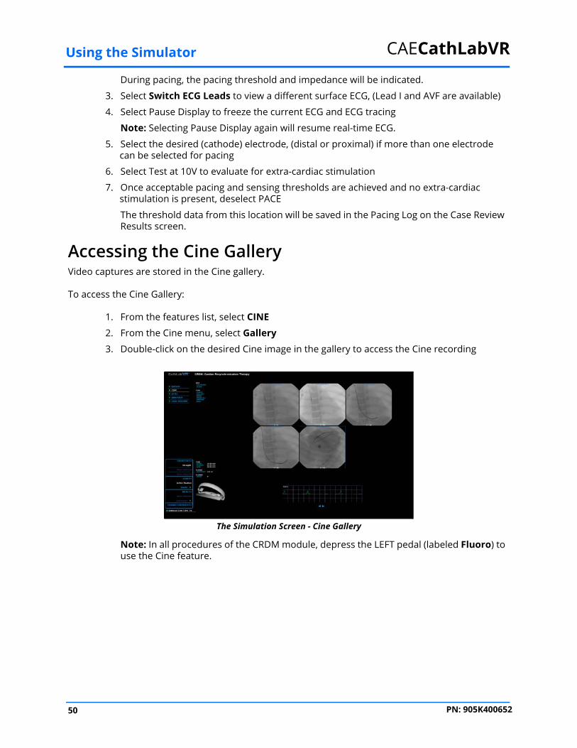
Accessing the Cine GalleryVideo captures are stored in the Cine gallery.
To access the Cine Gallery:
1. From the features list, select CINE
2. From the Cine menu, select Gallery
3. Double-click on the desired Cine image in the gallery to access the Cine recording
The Simulation Screen - Cine Gallery
Note: In all procedures of the CRDM module, depress the LEFT pedal (labeled Fluoro) to use the Cine feature.
50 PN: 905K400652

Using the Simulator
Accessing the Stills GalleryStill images of the video captures are stored in the Stills gallery.
To access the Stills Gallery:
1. From the features list, select STILL
Note: The still frame is the last image frame captured by pausing a Cine recording. The stills feature also captures the frame displaying the most contrast injection from the most recent Cine video or the selected Cine video.
2. From the Stills menu, select Gallery
3. Double-click on the Stills image in the gallery to access the Still frame
Ending a SimulationThe CathLabVR simulator has two ways in which a simulation can end.
In some cases, the learner makes a procedural error and is unable to correct the error within the allotted time for the simulation.If a learner performs a fatal error, the simulation will end before the time expires.
Learners also have the option to stop a simulation at any time during the procedure.
To end a simulation manually, from the simulation screen, click the End Simulation button.
The Simulation Screen
The End Simulation button
51PN: 905K400652

Using the Simulator CAECathLabVR
Viewing ResultsOnce the simulation is complete, the Results screen appears.
The Results Screen
Users can review the different metrics recorded from the procedure, including but not limited to, total fluoroscopy time, times and amounts of contrast dye injections, and other procedure-specific objectives.
52 PN: 905K400652

Using the Simulator
Viewing Personal DataTo view personal data, click the My Profile icon.
The Icon Dashboard
The Personal Data Screen
The MyProfile
icon
53PN: 905K400652

Using the Simulator CAECathLabVR
Viewing Usage SummariesTo view usage summaries, click the Usage icon.
The Icon Dashboard
The Usage Summary Screen
The Usage icon
54 PN: 905K400652

Using the Simulator
Viewing ReportsLearners can view customized reports from the Reports screen.
To view reports:
1. Click the Reports icon
The Icon Dashboard
The Reports Screen
The Reports icon
55PN: 905K400652
Using the Simulator CAECathLabVR
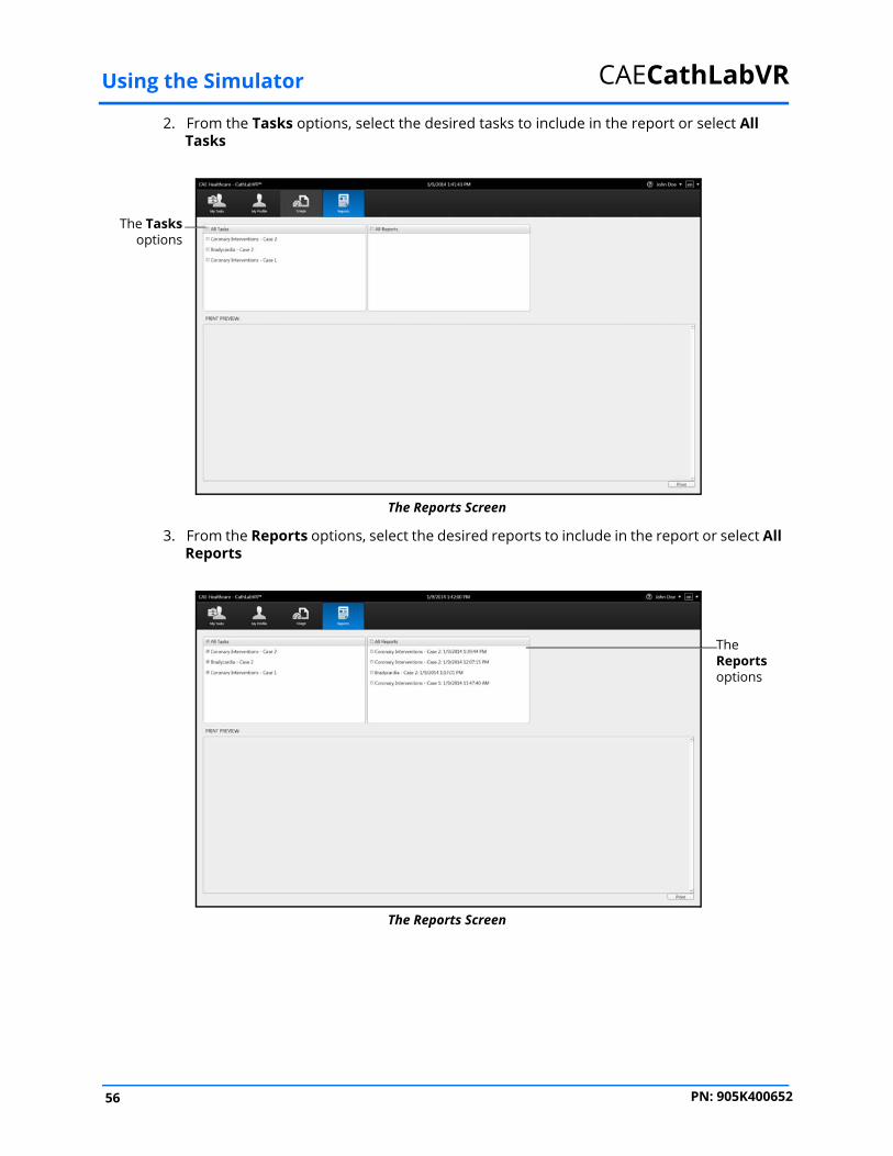
2. From the Tasks options, select the desired tasks to include in the report or select AllTasks
The Reports Screen
3. From the Reports options, select the desired reports to include in the report or select All Reports
The Reports Screen
The Tasksoptions
The Reports options
56 PN: 905K400652
Using the Simulator
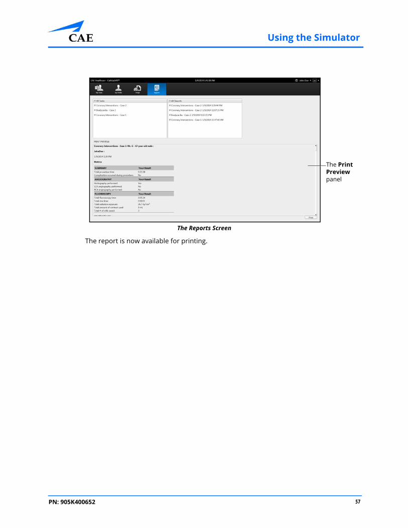
The Reports Screen
The report is now available for printing.
The Print Preview panel
57PN: 905K400652

Using the Simulator CAECathLabVR
Printing Data from the SimulatorLearners can print the data from the Results screen after completing a task. The print feature is also available on the Personal Data, Usage Summaries and Reports screens.
The Reports screen is the only screen that requires the learner to select the data to include in the report and generate a print preview prior to printing.
Printing Data to a Network PrinterA network connection is required for printing to a network printer. Contact your administrator for further assistance.
To print data to a network printer:
1. From the selected screen, click the Print button located near the bottom right corner of the screen
The Results Screen
The Print button
58 PN: 905K400652

Using the Simulator
Note: The Print button on the Personal Data screen is located near the top right corner of the screen.
The Results Screen
The Print Window
2. Select the desired network printer
3. Click Print
The Print button
The Print button
59PN: 905K400652

Using the Simulator CAECathLabVR
Printing Data to a PDF FileIf network connection is not available or no network printers are available, users can print data to a PDF file and save the file to an external device to print on a computer with a network printer connection.
To print the data to a PDF file:
1. From the selected screen, click the Print button located near the bottom right corner of the screen
The Results Screen
The Print Window
2. Select the PDF Complete program
The Print button
The Print button
60 PN: 905K400652
Using the Simulator
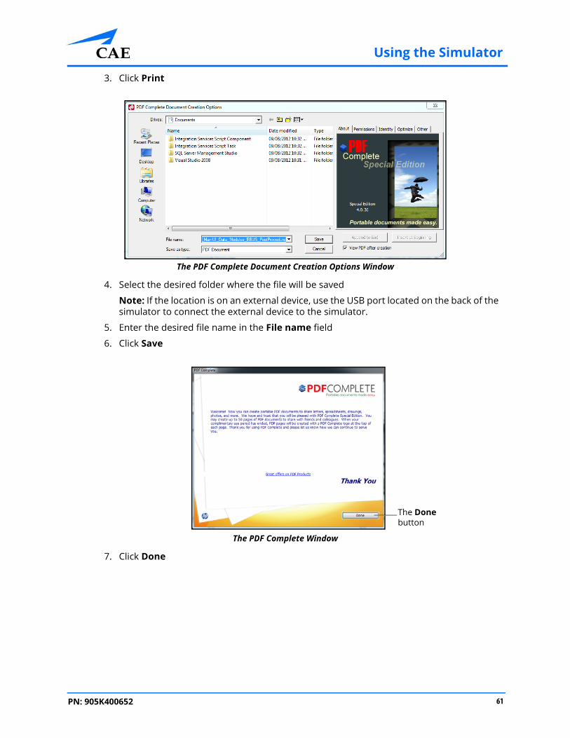
3. Click Print
The PDF Complete Document Creation Options Window
4. Select the desired folder where the file will be saved
Note: If the location is on an external device, use the USB port located on the back of the simulator to connect the external device to the simulator.
5. Enter the desired file name in the File name field
6. Click Save
The PDF Complete Window
7. Click Done
The Done button
61PN: 905K400652

Using the Simulator CAECathLabVR
The PDF Complete Special Edition window appears with the completed PDF.The PDF Complete Window
Modifying Language PreferencesLearners can change the language settings for their personal account using the language preferences menu in the top right corner of the screen.
To modify the language preferences:
1. Click the Language Preferences menu
The Home Screen
2. Select the preferred language from the drop-down menu
A checkmark appears next to the selected language and the language is applied to the software.
Note: Since the CathLabVR software is currently only available in English, no other options are available to set as the default language.
The Language Preferences menu
62 PN: 905K400652

Using the Simulator
Adjusting the VolumeLearners can adjust the volume of the simulator sounds by using the hotkeys on the simulator keyboard.
To increase the volume, press the Ctrl key and the Up arrow on the simulator keyboard simultaneously until the desired volume is achieved.
To decrease, press the Ctrl key and the Down arrow on the simulator keyboard simultaneously until the desired volume is achieved.
Hiding the Available Tasks PanelLearners can hide the Available Tasks panel to view the didactic content in full screen mode.
To hide the Available Tasks panel:
1. From the icon dashboard, click the My Tasks icon
2. From the Available Tasks panel, select the desired task
The Home Screen
3. Click the Hide Available Tasks arrow
The didactic content expands to the width of the full main screen.
The HideAvailable
Tasks icon
The main screen
The AvailableTasks panel
63PN: 905K400652

Using the Simulator CAECathLabVR
Exiting the SoftwareLearners should log out of the software once they are completed with their training session.
To exit the software:
1. Click on the username in the top right corner of the screen
The Home Screen with Logout Drop-Down Menu
2. Select Logout from the drop-down menu
The Login Screen
The Logout drop-down menu
64 PN: 905K400652

Frequently Asked Questions
FREQUENTLY ASKED QUESTIONSThe following tables describe some common user questions and solutions for the CathLabVR simulator.
Software Questions
Why do I receive the message, “Please Remove the Current Tool” when attempting to select a tool from the Tools menu?
This message indicates that the “carriage” that captures that tool is not in the ‘home’ position, or already has a tool, (or something else), inside it.
If you are using the simulator for the 1st time, con-firm that the shipping restraint has been removed from the carriages and restart the simulation. For more information, see the Setup section of this Admin Guide. Restarting the simulation module and case should cause all carriages to return to the ‘home’ position.
If there is no tool in the carriage, open the lid of the device and confirm that the carriage in question is in the ‘home’ position. The ‘home’ position is to the far right of the device, in contact with the carriage pre-ceding it, or, (in the case of carriage 1, against the far right of the device). If the carriage is not in the ‘home’ position, restart the simulation and case. This should automatically return all carriages to the ‘home’ position.
If a tool is present in the carriage, withdraw it until it reaches ‘home’ and continue to pull GENTLY on the tool, keeping it in the ‘home’ position while using the “No Tool” command, to de-select the tool.
If the carriage is in the ‘home’ position, no tool is captured within the carriage, and you have re-started the simulation, and continue to get the “Please Remove the Current Tool” message, there may be a piece of broken tool/wire within the car-riage, or, the simulator is not recognizing when the carriage is ‘home’.
65PN: 905K400652

Frequently Asked Questions CAECathLabVR
Why isn’t the simulator capturing my tools when I insert them?
The tool is damaged, is not entering carriage capture mechanism, or the capture mechanism is not functioning.
Verify that the tool has been selected within the simulation software. Tools must be selected prior to insertion, so that the SmartCapture™ mechanism will know which carriage should ‘capture’ the incoming tool.
If the tool appears not to capture within the carriage, attempt to twist and advance the tool, multiple times, if necessary. The tip of the tool may be ‘catching’ on the transition ‘funnel’ at the entrance of each carriage. This occurs especially when the tool is curved or bent).
If multiple attempts fail to capture, remove the tool and inspect it to verify that the tool is not bent, broken or kinked. Even small curves/kinks may prevent the tool from capturing successfully in the device. Re-test capture with a new/undamaged tool. If this new tool fails to capture;
Open the lid of the CathLabVR™ device and inspect the carriage where the wire/tool is to be captured. If the carriages are not in their ‘home’ positions, (see above), they cannot open and capture a tool. Manually slide the carriage until it is in contact with the carriage to its right or against the far right of the device, (‘home’ position), and try to insert/capture the tool again. Note that between carriages #3 and #4 there is a “guide tube” to help direct the guide wire into carriage #4. If this tube is bent/damaged, the wire may not be able to enter carriage #4. If this occurs, please contact CAE for assistance.
If the tool is inserted into the carriage properly and slowly, and the carriage does not attempt to capture the wire/tool, exit the simulation and reselect the module.
66 PN: 905K400652

Frequently Asked Questions
Hardware QuestionsWhy can’t I remove the wire/tool from the simulator?
The carriage capture mechanism has malfunctioned.
Make sure that the tool has been “de-selected” by going to the appropriate tool menu and selecting “NoTool”. Remember that if several “No Tool” choices are available, the “No Tool” beneath the dialog box where the tool was chosen must be selected to release the tool.
If the tool was “de-selected”, as above, and still does not release, end and quit the case by selecting “Exit”, (lower right corner of right simulation screen). This will return the software to the CAE ‘desktop’. Carriages should automatically release all tools and return to ‘home’ position.
If this fails to release the tool, turn off the power to the CathLabVR™ device. Turn the power back on while applying GENTLE traction to the wire/tool.
If this still fails to release the tool, open the lid of the CathLabVR™ device. Identify the carriage that is ‘holding’ the tool. Make sure that the ‘release lever’ is in the up, (no tool captured), position.
If the lever is not up, carefully raise the lever, using your fingers. This should release the tool. It is possible that another, more proximal carriage has accidentally captured the tool. Inspect and make sure all of the carriages have the release lever in the up position.
If none of the maneuvers described above allow the stuck tool to be removed, please contact CAE Customer Service.
Why doesn’t the Fluoro or Cine features work when I step on the foot pedals?
The foot pedal cable may be plugged into incorrect connector port.
Verify that foot pedal cable is inserted into Foot Pedal port “A”.
67PN: 905K400652

Frequently Asked Questions CAECathLabVR
Why aren’t the instrumented tools functioning properly/at all?
The tools are not plugged-in properly, not recognized by the software or broken.
If any “instrumented” tools are not working properly/at all, first verify that they are connected to their proper accessory connector. Once the tool location has been verified, and the tool properly connected, re-test the tool in a simulation case.
If the above steps do not correct the instrumented accessory tool function, the tool itself may be broken. If possible, replace with another instrumented tool, and return the defective tool to CAE.
Why isn’t the speaker working?
The speaker is not plugged in, is broken or volume turned down/muted in software.
Verify that sound bar is plugged in to proper connection on back of CPU and is connected to power source. Be sure volume is turned ON!
Using the “Windows” key, or from the desktop, selecting the Start Menu > My Computer > Control Panel, select Speaker Volume and make sure volume is high enough, and not muted.
If speaker is properly connected and software enabled, (volume high and not muted), speaker may be broken. In this case, contact CAE Customer Service to return speaker for instructions on returning the speaker for repair/replacement.
Why won’t the tools enter the simulator when using gentle pressure?
The tool is not entering carriage, is not selected in software, or there is a carriage/ “SmartCapture™” malfunction.
Make sure the tool has been selected in the software. Ensure that the tool has no kinks, bends or breaks. If it is damaged, replace with an undamaged tool. If the tool is in good working order, gently rotate it while inserting it into the device. This gentle rotation should facilitate tool insertion into the device.
If the tool will not enter the device after following Steps 1 and 2 above, please contact CAE Customer Service.
68 PN: 905K400652

Module Descriptions
APPENDIX A - MODULE DESCRIPTIONS
The CathLabVR simulator contains several modules for learners to practice performing endovascular procedures using different techniques and tools. Modules are bundled in four separate categories: Cardiac Rhythm Disease Management, Cardiac Surgery, Percutaneous Coronary Intervention and Percutaneous Peripheral Interventions.
The following table outlines the categories and modules offered for the CathLabVR simulator.
Category Module Description
Cardiac Rhythm Disease Management
Bradycardia Complete common tasks involved in resolving bradycardia in a patient.
Cardiac Resynchronization Therapy
Complete common tasks involved in cardiac resynchronization therapy.
Cardiac Surgery Transcatheter Aortic Valve
Complete common tasks associated with a transcatheter aortic valve intervention (TAVI).
Percutaneous Coronary Intervention
Coronary Interventions
Complete common tasks associated with a basic coronary intervention.
Coronary Interventions (Advanced)
Complete common tasks associated with an advanced coronary intervention.
Percutaneous Peripheral Interventions
Carotid Interventions
Complete common tasks associated with a basic carotid intervention.
Carotid Interventions (Advanced)
Complete common tasks associated with an advanced carotid intervention.
71PN: 905K400652

Module Descriptions CAECathLabVR
Module Instruments and Required EquipmentIn each of the modules, different instruments and features are used to complete the selected task.
Cardiac Rhythm Disease Management (CRDM)The Cardiac Rhythm Disease Management (CRDM) modules give learners an opportunity to practice and master techniques required to perform a CRDM corrective procedure.
Cardiac SurgeryThe Cardiac Surgery modules give learners an opportunity to practice and master techniques required to perform a transcatheter aortic valve corrective procedure.
Module Available Instruments Available Features
Bradycardia • Catheters
• Lead
• Wire
• Fluoro
• Analyzer
• Lead Fixation
• Custom Wire
Cardiac Resynchronization
Therapy
• Catheters
• Lead
• Wire
• Fluoro
• Analyzer
• Fixate Lead
• Customize Wire
Module Available Instruments Available Features
Transcatheter Aortic Valve • Catheters
• Wire
• Fluoro
• Customize Wire
72 PN: 905K400652

Module Descriptions
Percutaneous Coronary Interventions (PCI)The Percutaneous Coronary Interventions (PCI) modules give learners an opportunity to practice and master techniques required to perform basic and advanced PCI procedure.
Module Available Instruments Available Features
PCI: Coronary Interventions • Guidewire
• Catheters
• Balloon
• Stent
• Embolic Protection
• Aspirate
• Adjunct Therapy
• Fluoro
• Customize Guidewire
• Customize Embolic Protection
PCI: Advanced Coronary Interventions
• Guidewire
• Catheters
• Balloon
• Stent
• Embolic Protection
• Aspirate
• Adjunct Therapy
• Fluoro
• Customize Guidewire
• Customize Embolic Protection
73PN: 905K400652

Module Descriptions CAECathLabVR
Percutaneous Peripheral Interventions (PPI)The Percutaneous Peripheral Interventions (PPI) modules give learners an opportunity to practice and master techniques required to perform a basic and advanced PPI procedure.
Module Available Instruments Available Features
PPI: Carotid Interventions • Guidewire
• Catheters
• Balloon
• Stent
• Embolic Protection
• Aspirate
• Adjunct Therapy
• Fluoro
• Customize Guidewire
PCI: Advanced Carotid Interventions
• Guidewire
• Catheters
• Balloon
• Stent
• Embolic Protection
• Aspirate
• Adjunct Therapy
• Fluoro
• Customize Guidewire
74 PN: 905K400652
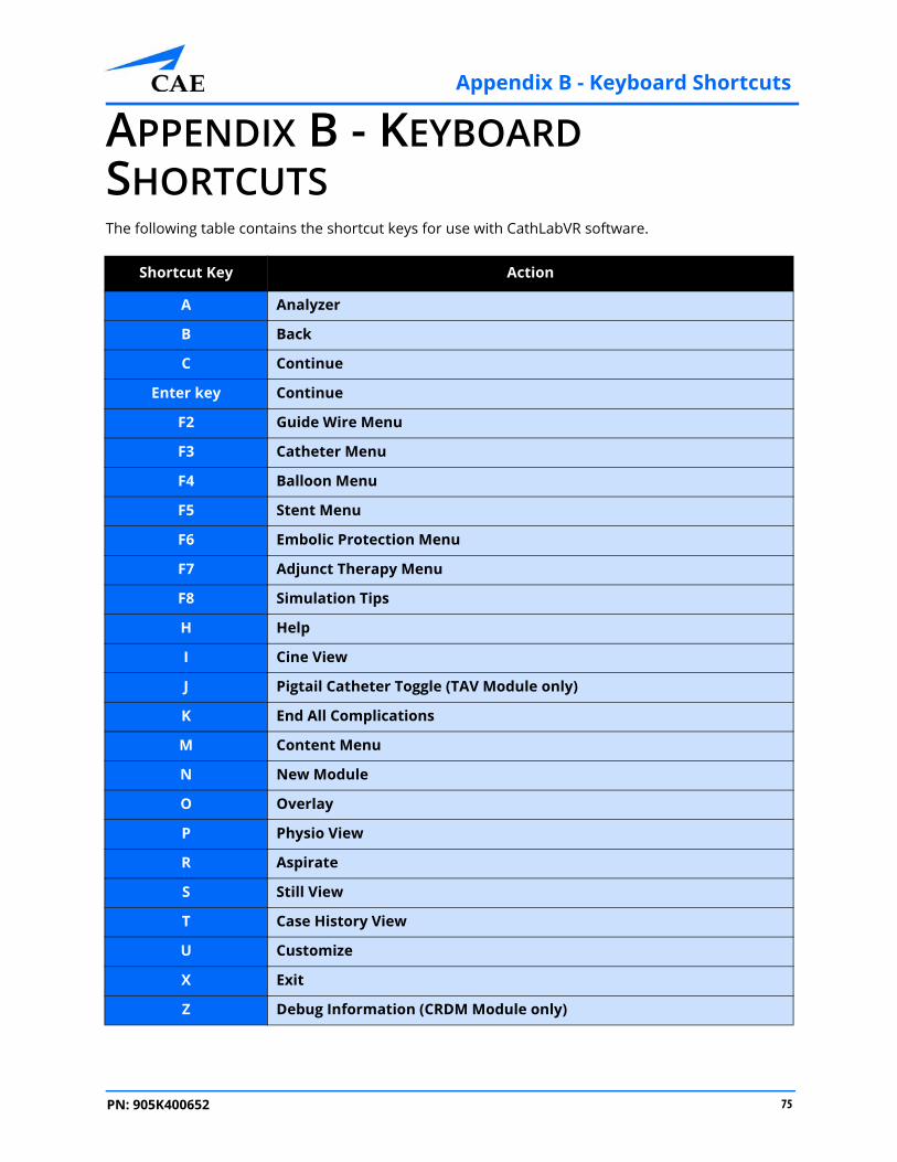
Appendix B - Keyboard Shortcuts
75PN: 905K400652
APPENDIX B - KEYBOARD SHORTCUTSThe following table contains the shortcut keys for use with CathLabVR software.
Shortcut Key Action
A Analyzer
B Back
C Continue
Enter key Continue
F2 Guide Wire Menu
F3 Catheter Menu
F4 Balloon Menu
F5 Stent Menu
F6 Embolic Protection Menu
F7 Adjunct Therapy Menu
F8 Simulation Tips
H Help
I Cine View
J Pigtail Catheter Toggle (TAV Module only)
K End All Complications
M Content Menu
N New Module
O Overlay
P Physio View
R Aspirate
S Still View
T Case History View
U Customize
X Exit
Z Debug Information (CRDM Module only)
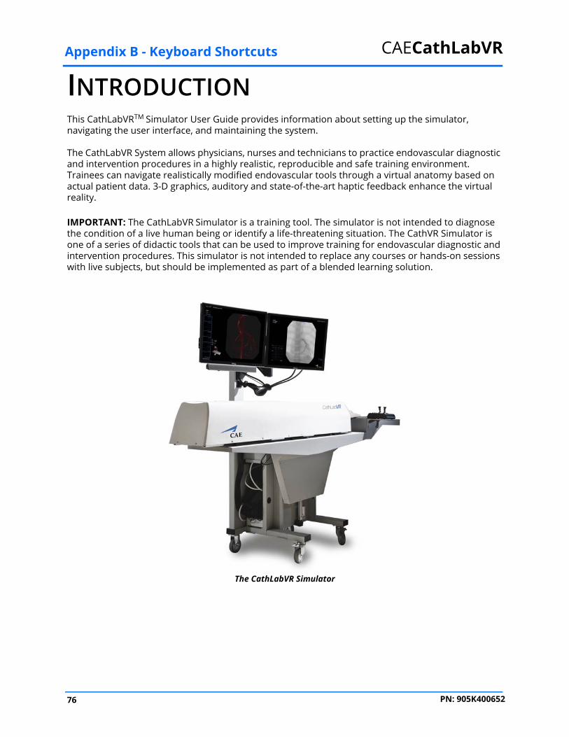
Appendix B - Keyboard Shortcuts CAECathLabVR
INTRODUCTIONThis CathLabVRTM Simulator User Guide provides information about setting up the simulator, navigating the user interface, and maintaining the system.
The CathLabVR System allows physicians, nurses and technicians to practice endovascular diagnostic and intervention procedures in a highly realistic, reproducible and safe training environment. Trainees can navigate realistically modified endovascular tools through a virtual anatomy based on actual patient data. 3-D graphics, auditory and state-of-the-art haptic feedback enhance the virtual reality.
IMPORTANT: The CathLabVR Simulator is a training tool. The simulator is not intended to diagnose the condition of a live human being or identify a life-threatening situation. The CathVR Simulator is one of a series of didactic tools that can be used to improve training for endovascular diagnostic and intervention procedures. This simulator is not intended to replace any courses or hands-on sessions with live subjects, but should be implemented as part of a blended learning solution.
The CathLabVR Simulator
76 PN: 905K400652
Appendix B - Keyboard Shortcuts
Contained in this User GuideThis User Guide has been designed for quick access to information on how to use and maintain the CathLabVR Simulator. Please be sure to read and follow the Cautions and Warnings on the pages preceding the Table of Contents. This is for the safety of users as well as for the protection of the simulator.
The Equipment Overview outlines the items that come standard with the purchase of a CathLabVR base unit.
The Using the Simulator section provides instructions on the use of the various tools and hardware features integrated into the simulated experience. This section also includes information on how the simulator and software components work and the functionality that each supports. Various surgical procedures are explained, along with how these procedures isolate critically important learning objectives.
The Frequently Asked Questions section addresses some of the more common troubleshooting concerns.
The Module Descriptions appendix outlines the specific tools and accessories that should be used in each of the procedures for the CathLabVR.
The Keyboard Shortcuts appendix describes the shortcut keys and their functions for the CathLabVR.
77PN: 905K400652

Appendix B - Keyboard Shortcuts CAECathLabVR
78 PN: 905K400652

Upgrade Instructions & Embedtek Specs
APPENDIX C - UPGRADE INSTRUCTIONS AND EMBEDTEK COMPUTER SPECIFICATIONSMedtronic CathLab VR™ Upgrade instructionsProper operation of the simulator requires correct configuration. Follow this sequence of the steps to upgrade the Medtronic CathLab VR system software from a Windows® XP computer to a Windows® 7 computer.
To connect a Windows 7 computer (that has upgraded Medtronic CathLab VR software) with an existing CathLab VR device:
1. Turn the computer ON
2. Connect the computer to the CathLab VR device with a USB cable
3. Connect the CathLab VR device to a power outlet
4. Turn the CathLab VR device ON
5. Start Calibration of CathLab VR HW:
a.From the computer, select Start > All Programs > CAE Healthcare > Medtronic CRDM > Calibrate CathLab VR HW
The File Location
The calibrate file
79PN: 905K400652

Upgrade Instructions & Embedtek Specs CAECathLabVR
b.Click Start on the EV 3.0 calibration screen to start friction calibrationThe Calibration Window
c.Click OK when the calibration is complete
The Calibration Window
6. Register OCX:a.From the computer, open the C:\Medtronic CRDM folder
The Start button
The OK button
80 PN: 905K400652

Upgrade Instructions & Embedtek Specs
b.Double-click the file Register CRDM.OCX.bat to run the register
The Register File
c.Click OK when the register is complete and succeeded
The Succeeded Window
Repeat the same steps for PCI and EDGE products.For PCI:a.From the computer, open the C:\Medtronic PCI folderb.Double-click the file Register PCI.OCX.bat to run the registerc.Click OK when the register is complete and succeededFor EDGE:a.From the computer, open the C:\Medtronic EDGE folderb.Double-click the file Register EDGE.OCX.bat to run the registerc.Click OK when the register is complete and succeeded
To run Medtronic, click the PCI, SRDM, or EDGE icon on the computer desktop.
The Icons
The register file
81PN: 905K400652

Upgrade Instructions & Embedtek Specs CAECathLabVR
Embedtek Tower Workstation Specifications:• Dimensions
º 17” H x 6.75” W x 18.36” D (43.2 cm H x 17.2 cm W x 46.6 cm D)
• Weight
º 19 lbs (8.6kg)
• C226 Embedded ATX Motherboard
º Super Micro X10SAE
º 2 Open PCI slots
º 1 Gen3 PCIex16 slot
º 6 USB 2.0 (4 front, 2 rear)
º 4 USB 3.0 (rear)
• CPU
º Intel i7 4770
º 3.4 GHz
º 4 Cores
º 8 Threads
º 8 MB cache
• 16 GB Ram (only 4 GB usable on 32 Bit OS)
• Video Card
º Nvidia GTX770 w/4 GB
º EVGA 02G-P4-2270-KR
• Hard Drive
º 1 TB
º 7200 RPM
º SATA 6.0 Gb/s
º 64 MB Cache
º 3.5”
• Windows 7 Professional 32 Bit
• Power Supply
º Seasonic SS600ES
º 600 Watts
82 PN: 905K400652


caehealthcare.com
For more information about CAE products, contact your regional sales manager
or the CAE distributor in your country, or visit caehealthcare.com.
Tel +1 941-377-5562 or 866-233-6384
For customer service, please contact CAE.
Customer Service Headquarters - United States and Latin AmericaMonday - Friday from 7:00 a.m. to 6:00 p.m. ETPhone 1-866-462-7920Email: [email protected]
Customer Service - CanadaMonday - Friday from 8:00 a.m. to 5:00 p.m. ETPhone 1-877-223-6273Email: [email protected]
Customer Service - Europe, Middle East, Africa, India, Asia and AustraliaMonday - Friday from 8:00 a.m. to 5:00 p.m. CETPhone +49 (0) 6131 4950354Email: [email protected]
Customer Service - United Kingdom and IrelandMonday - Friday from 9:00 a.m. to 5:00 p.m. GMTPhone +44 (0)800-917-1851Email: [email protected]
©2018 CAEPart #905K400652