use of the eclipse modeling framework -...
TRANSCRIPT

Use of the Eclipse Modeling Framework
and application to the GeoTools and GeoAPI environmentBryce Nordgren
USDA Forest Service

LegalNOTICE OF RELEASE TO THE PUBLIC DOMAIN
This work was created by employees of the USDA Forest Service's Fire Science Lab on official time funded by public money. It is therefore ineligible for copyright under title 17, section 105 of the United States Code. You may treat it as you would treat any public domain work: it may be used, changed, copied, or redistributed, with or without permission of the authors, for free or for compensation. You may not claim exclusive ownership of this work because it is already owned by everyone. Use this documentation entirely at your own risk. No warranty of any kind is given.
Complete details are provided via the US Government's public websites:
• http://www.copyright.gov/title17/92chap1.html#105
• http://www.gpoaccess.gov/uscode/ (enter "17USC105" in the search box.)
ii

Table of Contents1 Introduction..........................................................................................................................................................12 The GeoTools/GeoAPI environment....................................................................................................................13 Implementation Goals..........................................................................................................................................24 Relevant Characteristics of EMF.........................................................................................................................2
4.1 Distinction between attributes and references.............................................................................................24.2 Distinction between Classes and Data Types..............................................................................................34.3 Distinction between Classes and Interfaces................................................................................................34.4 Inheritance and Interface Implementation....................................................................................................34.5 Distinction between Ecore model and code generator.................................................................................34.6 Interfaces which are not modeled................................................................................................................44.7 Package orientation.....................................................................................................................................44.8 Multiplicitymany structural features.............................................................................................................4
5 Implementation Patterns......................................................................................................................................55.1 Representation of external Interfaces..........................................................................................................5
5.1.1 Indistinguishable Proxy Objects...........................................................................................................55.1.2 Dualusage patterns............................................................................................................................55.1.3 Summary.............................................................................................................................................6
5.2 Gateway Attributes......................................................................................................................................65.3 Associations.................................................................................................................................................7
5.3.1 Naming pattern....................................................................................................................................75.4 Lists and Sets..............................................................................................................................................7
6 Implementation Checklist.....................................................................................................................................86.1 Model proxy objects for interfaces...............................................................................................................86.2 Classify GeoAPI methods ...........................................................................................................................86.3 Model proxy objects for data types..............................................................................................................86.4 Create Ecore model.....................................................................................................................................86.5 Create Generator Model from Ecore model.................................................................................................96.6 Generate implementation code....................................................................................................................9
6.6.1 Automatic code generation..................................................................................................................96.6.2 Manually provide implementations.......................................................................................................9
6.7 Generate unit tests......................................................................................................................................96.7.1 Automatic test generation....................................................................................................................96.7.2 Manual test generation........................................................................................................................9
7 A worked example...............................................................................................................................................97.1 NameSpace Design ....................................................................................................................................97.2 Modeling Prework.....................................................................................................................................11
7.2.1 Interface proxies................................................................................................................................117.2.2 Classification of GeoAPI methods.....................................................................................................127.2.3 Data Type Proxies.............................................................................................................................13
7.3 Create Ecore model...................................................................................................................................147.3.1 Create the proxy objects....................................................................................................................15
iii

7.3.2 Define the implementation classes....................................................................................................16
iv
1 IntroductionThis document outlines the application of the Eclipse Modeling Framework (EMF) to the task of implementing GeoAPI interfaces within the GeoTools library. The initial implementation problem concerns the area of the Coverage family of classes as specified in ISO 19123. This document is intended to establish and document patterns in the implementation, as well as to record lessons learned during this initial effort.
The particular application with which this document concerns itself is relatively unique and is not directly addressed by the existing literature on EMF. In particular, the implementation effort revolves around the modeling of a set of classes which implement nonmodeled interfaces. This document will of course cover the technical details related to such an enterprise.
However, there are additional complications. The GeoAPI interfaces, which are to be implemented, do not contain all the information embodied in the design they represent. The most obvious form of information loss is the total absence of “associations” when the design is expressed in terms of java interfaces. Certainly the original UML designs typically contain associations where relevant. EMF's normal facility for discriminating attributes from associations in modeled classes does not cover the case where the classes and the associations between them are external to the model. This document will also cover the subjective judgments required by the human model makers to recover this missing information for EMF.
Detailed information about EMF is not provided and this document should be viewed as supplementary material to a more thorough EMF reference. This document is not intended to replace a reference of the Eclipse Modeling Framework.
2 The GeoTools/GeoAPI environmentGeoAPI is an open source project administered by the Open Geospatial Consortium (OGC). It is an interfaceonly implementation of various geospatial standards. The intent of developing an interfaceonly implementation (which is usually an oxymoron) is to provide a means of sharing Java implementations among various projects. In other words, the OGC is not concerned with specifying how the standards are to be implemented, but in order to make implementations interoperable, a general structure and nomenclature must be specified. In addition, certain conventions must be adopted regarding the interpretation of data elements if the standards do not supply such an interpretation.
Thus explained, GeoAPI is a core around which implementations may crystallize. This is advantageous primarily because it provides a monolithic, vertically integrated structure. This structure is available to all, regardless of the vantage point from which they are viewing geospatial data. As such, implementors are free to select a specific subset of geospatial concepts of interest, and deal only with those concepts. This allows a group to focus their entire attention on, for instance, the implementation of geometry1, without burdening such a group with the associated concepts of coordinate reference systems or feature models. Permitting the crystallization of implementations around a common core should have the effect of coordinating the crystallization of groups of likeminded individuals around topics in which they have some personal or professional interest. In short, the added value of the GeoAPI library lies in the potential for coordinating development efforts which would
1 While this does not seem very complicated at first, the attendant difficulties of producing correct and robust code which can handle the nuances of computational geometry certainly deserve the undivided attention of dedicated individuals.
Page 1 The GeoTools/GeoAPI environment
otherwise be totally unrelated.
GeoTools is a single implementation of the GeoAPI interfaces. In GeoTools, many different logical subsets of the GeoAPI interfaces are provided with implementations. It should be taken as a given that GeoTools implementation strategies should be isolated from the GeoAPI interfaces.
This section exists solely to make this point: GeoAPI is outside any EMF modeling described in this document. EMF is part of an implementation strategy which is to be firmly contained within the GeoTools library. This statement has two corollaries:
1. GeoAPI interfaces will not be modeled by EMF.
2. GeoAPI interfaces are represented in EMF by “placeholder” classes, marked as interfaces, with the “instanceClass” property set to the fully qualified name of the interface.
EMF will, of course, generate interfaces and implementation classes in the GeoTools namespace. Therefore, the implementation is an implementation of the GeoAPI and GeoTools versions of the same interfaces. This is in contrast to the rest of the GeoTools code base, which tends toward the direct implementation of GeoAPI interfaces without an intervening layer.
3 Implementation GoalsThis section contains a collection of goals which should be aspired to during any GeoTools implementation effort where GeoAPI interfaces are the target. These goals are intended to encourage interoperability.
1. Parameters and return values must match the GeoAPI interfaces exactly. This is, of course, required by Java. The benefit, which it is worthwhile to explicitly state, is that foreign objects
4 Relevant Characteristics of EMFThis chapter collects together relevant characteristics of EMF. These characteristics are described but not interpreted. The following chapter will take the data gathered here and interpret it to establish effective and legitimate patterns of use.
4.1 Distinction between attributes and referencesAttributes and References are both known as “structural features” of a class. Both attributes and references cause the code generator to provide setter and getter methods. As such, the exposed API of both conform to the nomenclature of Java Bean properties.
The crux of the difference between attributes and references is the way that these two structural features are typed. Attributes must be EDataTypes, and references must be EClasses. EDataTypes and EClasses are mutually exclusive groups.
Page 2 Distinction between attributes and references
4.2 Distinction between Classes and Data TypesFor those seeking a quick rule of thumb to determine the difference between classes and data types2, the following quote from Eclipse Modeling Framework does an admirable job of distilling the essence of the distinction: “EDataType models the types of attributes, representing primitive and object data types that are defined in Java, but not in EMF.” Meaning, anything not described by an EMF model is a DataType and anything which is modeled in EMF is a Class. By this rule of thumb, all GeoAPI interfaces should be DataTypes.
4.3 Distinction between Classes and InterfacesEMF uses a single attribute to differentiate between a Class and an Interface. If the “interface” property of the EClass definition is true, then the EClass models an interface. If false, it models a Class.
Both Classes and Interfaces, therefore, are modeled with an EClass.
4.4 Inheritance and Interface ImplementationClasses modeled in EMF may inherit from other classes, or implement interfaces. Both processes are similar, and are accomplished by identical means. Inheriting from a superclass is modeled by specifying the parent class in the “eSuperTypes” property of the child class. Likewise, modeling the implementation of an interface is accomplished by specifying the interface in the “eSuperTypes” property of the implementing class. This is a multivalued property, which permits the modeler to specify multiple parent classes and/or multiple interfaces3.
The “eSuperTypes” property accepts only members which are modeled with EClass, which of course excludes anything modeled as an EDataType.
4.5 Distinction between Ecore model and code generatorThe Ecore model contains exactly what it sounds like it contains: a model of the classes, data types, attributes and references for some subset of code. The code generator, on the other hand, marries the model with some extra metadata in order to adapt the model to the Java programming language.
The code generator, for instance, makes decisions on how to represent “multiplicitymany” attributes and references within the Java language. It has the same options that a human implementor would have. For example, it could use an array, List, Set, or other Collections interface.
The distinction between an Ecore model and the generated code is an extremely important one to make. The generated code is an interpretation of the Ecore model expressed in Java. The two are not identical. In fact, the assumption that constructing an Ecore model is always followed by the generation of code does not alawys hold. This last statement is extremely important because the code generator does make such an assumption. This assumption manifests itself when the code generator interprets references: the code generator considers itself at liberty to cast any modeled EClass object to an EInternalObject.
2 For a more detailed explanation of the difference, see section 5.2 of Eclipse Modeling Framework.3 Modeling multiple inheritance does not present a problem, as this is just a data structure. Generating code to represent
multiple inheritance requires an additional step from the modeler. Namely, since Java is a language which permits only singleinheritance, the modeler must indicate to the codegenerator which superclass occupies the “extends” clause.
Page 3 Distinction between Ecore model and code generator

This assumption is of particular concern to implementors of GeoAPI interfaces because, as will be shown later, implementing nonmodeled interfaces violates this assumption that the code generator relies on. This activity must be undertaken with great care.
4.6 Interfaces which are not modeledHandling an interface which is not present in the ECore model would seem to be a rather esoteric topic, as there are approximately two paragraphs devoted to it in the 670 page Eclipse Modeling Framework book. These paragraphs are not contiguous, but may be found in sections 9.1.4 and 9.5.3. However, as this esoteric topic is the core of GeoAPI implementation using EMF, they are collected here for easy reference:
Referring to an EClass with the interface property set to true: “If an instanceClass is specified, then a Java interface will not be generated, either. Instead, this class will be considered a proxy for an external interface that already exists, in the same way that data types...are used as proxies for external Java classes. This technique is useful for adding external Java interfaces to a generated interface's extends clause...” [Section 9.1.4]
“Recall that we can also model nonEMF interfaces, specifying only the name of the Java interface and not any attributes, references, or operations. In the case where such an interface is implemented by a class, the only thing affected is the extends clause of the interface generated for the implementing class. Since the model specifies nothing about the external interface, we will need to code, by hand, implementations of any methods that it declares.” [Section 9.5.3]
To summarize, in order to implement external interfaces with an EMF model:
1. The external interface must be represented by a proxy inside the model. This proxy is defined by an EClass with the “interface” property set to true, the “instanceClass” property set to the name of the external interface, and which possesses no attributes, references, or operations.
2. Every attribute, reference and operation defined by the external interface must be explicitly declared by the model of the implementing class. EMF has no knowledge of the external interface's structure and cannot automatically fill in the externally declared structural features.
4.7 Package orientationEMF is package driven. There is one Ecore model per java package. Models may refer to other models: this is how classes from other packages are included. Models may refer to external elements, but these external elements must be declared to be classes or data types prior to being used as superclasses, attributes, or references. Each Ecore model, which brings together the definitions of all the model elements contained within a single package, occupies a single file.
4.8 Multiplicitymany structural featuresThe primary difference between a Set and a List is that a Set contains unique, unordered members, and a List contains ordered members which may not be unique. In EMF, the uniqueness of members and whether they are ordered or not are properties of references and attributes. EMF, however, represents all multiplicitymany
Page 4 Multiplicitymany structural features

structural features with an Elist, which is a subinterface of a java.util.List. It does not represent any multiplicitymany features as a Set.
The fact that EMF represents all multiplicitymany features with an Elist does not mean that it disregards the “unique” or “ordered” properties. EMF supplies many implementations of the Elist interface, some of which support a restriction on the members such that they must be unique. The designation of a structural feature as unique informs the code generator as to which particular implementation of Elist is selected for use.
5 Implementation PatternsMany characteristics of EMF have been elicited in the preceding chapter. This chapter concentrates on organizing usage patterns which harness these characteristics in a logical manner. Whereas the previous chapter concentrated on the collection of data, this chapter will focus on data analysis. The objective is the synthesis of a coherent application of EMF to the current problem.
5.1 Representation of external InterfacesThe recommended proxy representation of external interfaces, as described in section 4.6, involves the definition of an EClass with no structural features, and an appropriately set “instanceClass” property. This permits the inclusion of the interface proxy in the “eSuperType” list of the implementing class, as required in section 4.4.
The problem, however, lies in the declaration of the interface's methods, in particular the parameter types and return types of the external interface. GeoAPI is highly selfreferential, as should be expected. However, this selfreferential nature leads directly to the presence of parameter and return types which, to EMF, are proxies for interfaces. Exactly why this is a problem will be shown in the following sections.
5.1.1 Indistinguishable Proxy ObjectsThe interfaceproxy is an EClass. As shown in section 4.2, the main distinguishing factor between an EClass and an EDataType is that an EClass is considered to be modeled with EMF, and an EDataType is considered to be an external definition. This leads to the assumption by the code generator (section 4.5) that any EClass could be cast to an EinternalObject if necessary. Apparently, the codegenerator does not check to ensure that the EClass is not a proxy prior to performing the case.
To summarize, the conceptual problem which leads to all this is that classes and interfaces modeled within EMF are considered to be the same thing: an EClass. However, the proxy object for a class is an EDataType, while the proxy object for an interface is an EClass. This directly leads to EMF's inability to distinguish an intentionally modeled class and a standin for an externally defined interface.
5.1.2 Dualusage patternsThere are two main uses for external interfaces in an EMF model which implements those interfaces:
1. The external interfaces must appear in the “eSuperType” list of the implementing class.
2. The external interfaces must appear as the type of various attributes, references, and operations,
Page 5 Dualusage patterns

defined in the implementing class.
The second point is where error is introduced if a proxy object is used to specify the type of the structural feature. An attribute specified by setter and getter methods in the GeoAPI interface must be modeled as a reference in EMF, due to the fact that the proxy object is an EClass. This is an error, because references are meant to exist between modeled elements only. This is the action which violates the assumptions of the code generator.
To remedy this situation, the two categories of use must be explicitly recognized and accounted for. In the first use case, that of implementing an external interface, an interface proxy is required. In the second case, that of referring to an externally defined type, a class proxy is needed. Modelers need to be aware of the distinction and must use the proxy object appropriate to the context of the use.
5.1.3 SummaryEMF supports two types of proxy objects for externally defined items. One of the proxy objects is indistinguishable from an intentionally modeled class. Inappropriate use of this proxy object outside the context within which it is known to be a proxy leads to violation of some basic assumptions about the interpretation of fundamental objects within the EMF framework. This misinterpretation of EMF objects causes the code generator to emit incorrect code.
All problems with proxy objects may be avoided by recognizing the two categories of proxy objects, recognizing the limitations of each, and carefully using the correct proxy in the correct situation. Namely: interfaceproxy objects belong in the eSuperType property of the implementing class (and only there.) Proxies for external types (e.g., an EDataType) belong wherever a type definition is called for. Both proxy objects are required to correctly implement external interfaces with EMF.
5.2 Gateway AttributesA problem facing implementors of GeoAPI using EMF is that any defined associations will need to be modeled as references between implementation classes. GeoAPI, however, is defined in terms of itself. Therefore, when an implementor chooses to model a relationship between two implementation classes, a corresponding derived attribute must be provided. This derived attribute exists solely to provide a “view” of the association in the terms specified by GeoAPI. The real work of maintaining the reference is done with the generated code.
A derived attribute which performs the function outlined in the previous paragraph will be called a “Gateway Attribute” in this document. This name reflects the fact that the attribute serves as a gateway between the implementation objects and the interfaces they implement.
Typically, to provide a GeoAPI implementation, one need only provide a “getter” method for the Gateway attribute. However, if the implementor has modeled the reference as “changeable,” the corresponding setter method should also be provided for the Gateway Attribute. Failure to provide this setter method will mean that clients will be able to set the property using the implementation objects, but not using the GeoAPI objects. The provided setter method should not assume that the GeoAPI interface is backed by this implementation, but should cause the foreign object to be copied into the corresponding object from this implementation, then set using the implementationspecific means.
Page 6 Gateway Attributes
Note that modeling an attribute in EMF does not involve this extra layer of complexity. Gateway attributes are required only where references are modeled.
5.3 AssociationsAssociations, especially bidirectional associations, benefit most from EMF code generation. Associations have implicit and obvious conceptual meaning, the implementation of which requires mundane template code. Template code, by which I mean code which fulfills a common, wellunderstood, and wellconstrained purpose is tedious to write, repetitive and is easy to write incorrectly. This type of coding is best left to an automated system.
There are three requirements of the human modeler with respect to “associations”:
1. The modeler must recognize the presence of an association in the design from which the GeoAPI interfaces were derived.
2. The modeler must express the association correctly in ecore as a reference between the implementation objects.
3. The modeler must provide the corresponding gateway attribute to properly express the association in terms defined by GeoAPI.
Modelers are encouraged to seek out associations and utilize EMF to model them wherever they are found.
5.3.1 Naming patternAn association causes the presence of two related properties in the implementation class. Each association has a corresponding reference and gateway attribute. These should be named such that their correspondence is obvious. Since the name of the gateway attribute is fixed by the GeoAPI interface, the name of the reference must be generated using the gateway attribute's name as a base.
For the purposes of this document, the implementing reference shall append the string “Ref” to the name of the gateway attribute.
5.4 Lists and SetsMany GeoAPI interfaces return Lists or Sets of specific types. In many cases, a List or Set in a GeoAPI interface represents a multiplicitymany association between two classes. In other cases, this might represent a multiplicitymany attribute. In nearly all cases, GeoAPI specifies readonly data access, leaving decisions concerning the means of setting data elements up to the implementor.
However, as noted in section 4.8, EMF represents all multiplicitymany structural features as an Elist, which is a type of List. That section also notes that if a feature is specified to be “unique”, then EMF will honor that designation, and prevent the addition of duplicate members. The major facility which EMF lacks is the ability to provide a “Set” view of a unique list.
The action to take depends on the context of the reference. If the implementor desires to return an object which is a copy of the current List, the solution becomes simple. A new set is constructed and populated with the
Page 7 Lists and Sets

contents of the Elist managed by EMF, using the constructor or the addAll() method. If the implementor needs to return a set view which is backed by the Elist, there is a problem. This problem must be solved by the implementor using the context provided by the situation.
Implementors are strongly encouraged to seek out the existence of an association whenever a Set or a List is encountered. If such an association can be found, it should be modeled as a reference and the required gateway attribute should be supplied.
6 Implementation Checklist
6.1 Model proxy objects for interfacesDetermine which GeoAPI interfaces are to be implemented by this package. Each interface must be defined as an empty Class with the “instanceClass” property set to the fully qualified name of the GeoAPI interface. This class definition is to be used only in the list of superTypes for the corresponding implementation class.
6.2 Classify GeoAPI methods All methods defined in the GeoAPI interfaces will fall into one of three categories:
1. The method is an accessor method for an attribute.
2. The method is an accessor method for a reference.
3. The method is an operation (anything not related to an attribute or reference).
6.3 Model proxy objects for data typesExamine the GeoAPI interfaces to generate a list of all the parameter types and return types referenced. Each one of these which is not already defined in EMF must be defined in the model as data types. These data type definitions are used whenever an attribute is modeled, gateway or otherwise.
6.4 Create Ecore modelThe ecore model is the target expression of all the work thus far accomplished. EMF is accompanied by default translators capable of converting between Ecore and one of XML Schema, Java Interfaces, or Rational Rose (a specific, commercial UML modeling program.) An entire chapter of the Eclipse Modeling Framework book is devoted to each one of these translation schemes. Of these mechanisms for creating a model which can be translated to ecore, Rational Rose is immediately eliminated because it is unavailable. XML Schema is unwieldy for two reasons: 1] one must learn the syntax; and 2] the predefined data type names are inconveniently long.
The Java interface importer suffers from a showstopping fault: its decision to model an external interface as a class proxy or a data type proxy is ruled by where the external interface is first encountered. If it is encountered in an “extends” clause, it is modeled as an interface proxy; if first encountered as a parameter or return type, it is modeled as a class proxy. This importer will not declare two separate representations of the same interface, as
Page 8 Create Ecore model
dictated by the discussion in section 5.1.
Fortunately, there is a fourth means of creating a model which allows precise control over the expression and settings of ecore properties. The Ecore model may be directly created and edited by the modeler. This may be accomplished in two ways: an XMI file may be created in a text editor, or the Ecore model may be created within Eclipse and edited with the graphical property editor.
Of these two approaches, the direct creation of XMI suffers from the same drawbacks as the XML Schema method. Namely, the syntax must be learned and the predefined type names are awkward. Editing the model in Eclipse using the property editor has the advantage that legal syntax is enforced by the editor. One may only add properties which are allowed to be contained within the containing object. When selecting the type of a property, only the legal values are displayed (e.g., Classes are displayed for references and DataTypes are displayed for attributes.)
6.5 Create Generator Model from Ecore modelTODO: supply description.
6.6 Generate implementation code
6.6.1 Automatic code generation
6.6.2 Manually provide implementations
6.7 Generate unit tests
6.7.1 Automatic test generation
6.7.2 Manual test generation
7 A worked example
7.1 NameSpace Design The class diagram in Figure 1 shows the original design of the NameSpace package. This is the design from which the GeoAPI interfaces are derived. The determination of whether a structural feature is a reference or an attribute will be made from this figure.
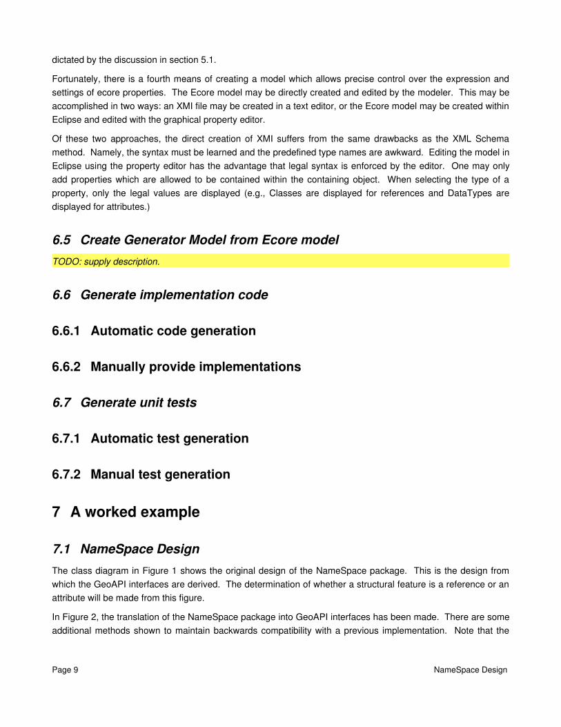
In Figure 2, the translation of the NameSpace package into GeoAPI interfaces has been made. There are some additional methods shown to maintain backwards compatibility with a previous implementation. Note that the
Page 9 NameSpace Design

associations shown in Figure 1 are not present in Figure 2.
Figure 1: Original design of the namespace package.
Page 10 NameSpace Design
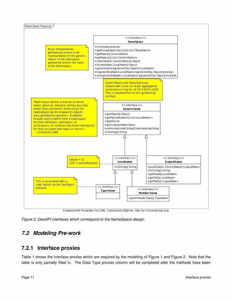
Figure 2: GeoAPI interfaces which correspond to the NameSpace design.
7.2 Modeling Prework
7.2.1 Interface proxiesTable 1 shows the interface proxies which are required by the modeling of Figure 1 and Figure 2. Note that the table is only partially filled in. The Data Type proxies column will be completed after the methods have been
Page 11 Interface proxies

classified.
Table 1: Specification of interface proxies
7.2.2 Classification of GeoAPI methodsThe chart in Table 2 itemizes the contents of the GeoAPI package to be implemented. All of the methods represented in the interfaces should be present here. Note, however, that Table 2 should be a specification of the implementation and not the interfaces. Subtle differences exist between Figure 2 and Table 2. Note, for instance, that the class “GenericName” does not contain the “parsedNames” property, even though the corresponding “GenericName” does have such a property. This is simply because “GenericName” does not know enough to generate this derived parameter. This intelligence is contained in the child classes. In the case of the LocalName, this derived parameter is a List with a single element, derived from the name object itself. In the case of a ScopedName, it is not “derived” at all, but is the actual storage of the list of names. The absence of this parameter is permitted by the fact that GenericName is abstract, therefore it does not have to implement everything in the GenericName interface so long as one of its children does implement it.
It is important to note in the table which parameters are derived and which are not. This saves time later, when generating the model. Derived parameters will need to be marked “derived” and “volatile”, to avoid having the code generator create storage for these calculated parameters. My notation of a “derived” parameter is the presence of a leading slash in the property name.
This is the point at which decisions are made as to whether properties are to be considered references, attributes, or operations. Operations are normally selfexplanatory. The decisionmaking process is required to make the distinction between references and attributes.
Finally, the “Type” column of the table collects in one place all of the DataTypes which require proxies. Of course, if the property has been classified as a “reference”, then the corresponding model of the type within EMF must be present as well (e.g., not an empty class proxy, but the full implementation model.) The type list for operations includes the type of each parameter as well as the return type. Note that generic collection types, where present, are specified in generic notation. This topic will return again later, when the Ecore model is reviewed.
Page 12 Classification of GeoAPI methods
GeoAPI Package: org.opengis.util.ns
Interface Proxies Data Type ProxiesNameSpaceGenericNameLocalNameScopedNameMemberNameTypeName
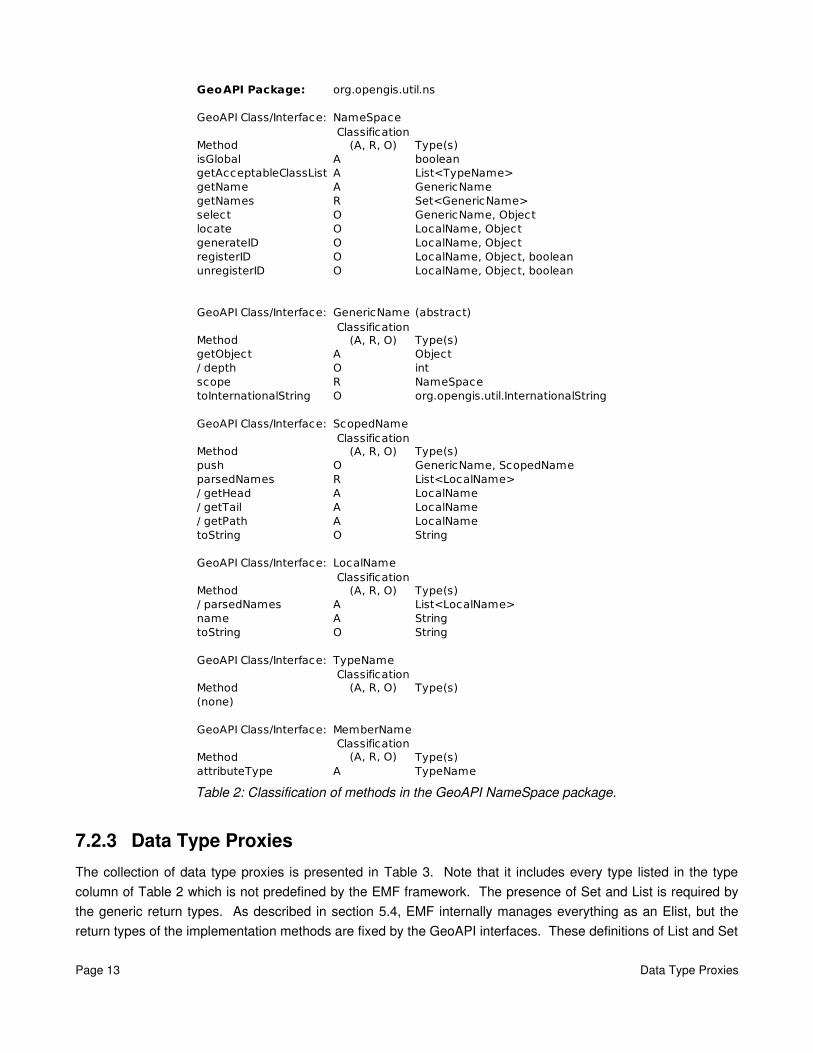
Table 2: Classification of methods in the GeoAPI NameSpace package.
7.2.3 Data Type ProxiesThe collection of data type proxies is presented in Table 3. Note that it includes every type listed in the type column of Table 2 which is not predefined by the EMF framework. The presence of Set and List is required by the generic return types. As described in section 5.4, EMF internally manages everything as an Elist, but the return types of the implementation methods are fixed by the GeoAPI interfaces. These definitions of List and Set
Page 13 Data Type Proxies
GeoAPI Package: org.opengis.util.ns
GeoAPI Class/Interface: NameSpace
Method Type(s)isGlobal A booleangetAcceptableClassList A List<TypeName>getName A GenericNamegetNames R Set<GenericName>select O GenericName, Objectlocate O LocalName, ObjectgenerateID O LocalName, ObjectregisterID O LocalName, Object, booleanunregisterID O LocalName, Object, boolean
GeoAPI Class/Interface: GenericName (abstract)
Method Type(s)getObject A Object/ depth O intscope R NameSpacetoInternationalString O org.opengis.util.InternationalString
GeoAPI Class/Interface: ScopedName
Method Type(s)push O GenericName, ScopedNameparsedNames R List<LocalName>/ getHead A LocalName/ getTail A LocalName/ getPath A LocalNametoString O String
GeoAPI Class/Interface: LocalName
Method Type(s)/ parsedNames A List<LocalName>name A StringtoString O String
GeoAPI Class/Interface: TypeName
Method Type(s)(none)
GeoAPI Class/Interface: MemberName
Method Type(s)attributeType A TypeName
Classification (A, R, O)
Classification (A, R, O)
Classification (A, R, O)
Classification (A, R, O)
Classification (A, R, O)
Classification (A, R, O)

are required by the gateway attributes.
Table 3: Completed proxy table for NameSpace package
7.3 Create Ecore modelThis example creates an Ecore model using the Eclipse editor, for reasons described in section 6.4. To pursue other means of creating an Ecore model, consult the correct documentation for that means.
The first step is to create a blank Ecore model. This is accomplished by clicking on File>New>Other... This brings up the dialog in Figure 3.
Figure 3: Creation of an Ecore model in Eclipse, Step 1
Page 14 Create Ecore model
GeoAPI Package: org.opengis.util.ns
Interface Proxies Data Type ProxiesNameSpace NameSpaceGenericName GenericNameLocalName LocalNameScopedName ScopedNameMemberName TypeNameTypeName org.opengis.util.InternationalString
java.util.Setjava.util.List

On the next screen, choose a location to store the ecore model on disk. The screen following the selection of storage location allows the selection of the “Model Object”. This is the top level (root) object in the generated XMI file. Select “Epackage,” as shown in Figure 4, then click on “Finish”.
Figure 4: Creation of an Ecore model in Eclipse, Step 3
The new ecore model is entirely blank. It has no name and it has no knowledge of the package location in the namespace. Both these problems are fixed in Figure 5. The Ns URI parameter specifies the package name for the implementation, and the Name parameter gives the package a short name for reference. The two items are not necessarily related. Note that the property list in the figure is displayed when the package is highlighted in the “Resource Set” window.
Figure 5: Naming the package and setting the package's namespace.
7.3.1 Create the proxy objectsUsing Table 3, create all proxy objects in the model, as shown in Figure 6. Note the symbology. The top six items are interface proxies, and the remainder are class proxies. The symbology of an interface proxy is identical to the symbology of a modeled class. This is in accordance with the discussion in section 5.1. Note that the instance class for each proxy object is listed right next to the name. I have adopted a nomenclature for this model such that interface proxies have the word “Interface” appended to the name, and class proxies have the word “Type” appended to the name. This is far from required, but some deterministic naming scheme should be adopted in every model for clarity.
Page 15 Create the proxy objects
Figure 6: Definition of Proxies in the new Ecore model
Note that none of the defined proxies have any properties other than the instanceClass. There are no methods, attributes or references defined, and neither is inheritance specified. EMF is to treat these proxies as placeholders, so no attempt is made to model them.
7.3.2 Define the implementation classesTo this point, we have been laying the groundwork for the actual content of the model: the implementation classes. A portion of the completed model is shown in Figure 7. Note that the implementation classes are fully fleshed out with the properties specified in Table 2.
In addition, Figure 7 demonstrates the presence and utility of gateway attributes. The “namesRef” property is associated with the “names” gateway attribute. As shown, the namesRef property has the type of an implementation class (and not one of the proxy types). The associated gateway property uses one of the proxy objects as a type, and is defined as volatile and derived (not shown.)
7.3.2.1 Bidirectional referencesNote that the “names” reference is defined as a bidirectional reference in Figure 1. This is handled in Figure 7 by the fact that the “EOpposite” property is set. To form a bidirectional reference, the modeler must first define both oneway references. (In this case, NameSpace contains a “namesRef” reference and GenericName contains a “scopeRef” reference, as specified in Figure 1.) When both references are defined, a bidirectional reference is formed by clicking on either reference, bringing up the EOpposite popup in the properties window, and selecting the other reference. The two oneway references are now linked as a bidirectional reference.
Page 16 Define the implementation classes
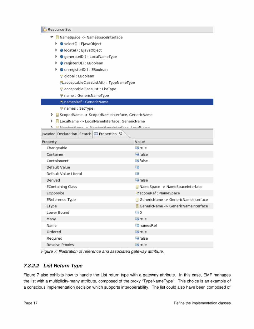
Figure 7: Illustration of reference and associated gateway attribute.
7.3.2.2 List Return TypeFigure 7 also exhibits how to handle the List return type with a gateway attribute. In this case, EMF manages the list with a multiplicitymany attribute, composed of the proxy “TypeNameType”. This choice is an example of a conscious implementation decision which supports interoperability. The list could also have been composed of
Page 17 Define the implementation classes
the TypeName implementation class. However, there was no need to specify the implementation class in this case. Whenever possible, choose to type structural features with the GeoAPI proxy objects, as this reduces the tendency to exclude objects from other implementations.
Note that the gateway attribute in this case is a multiplicity1 structural feature which returns a list. The intention is to supply an implementation for the getter of this method which creates and returns a copy of the internally managed list. Specifying the gateway attribute as derived and transient ensures that the generated getter method is blank.
7.3.2.3 SymbologyNote the symbology of structural features in Figure 7. An indication of multiplicity is given in each symbol. A symbol with no numbers or associated numeric range indicates that lower bound is 0 and upper bound is 1. The difference between an attribute and a reference can be seen in the symbol used. A box with an arrow represents a reference, and a box with no arrow represents an attribute. A gear represents an operation and a gear with an arrow represents a parameter to an operation.
Page 18 Define the implementation classes