use of rogowski coil as current transducer for distance...
TRANSCRIPT

International Journal on Electrical Engineering and Informatics - Volume 8, Number 4, December 2016
Use of Rogowski Coil as Current Transducer for Distance
Relay Reach Correction
Avinash Namdeo Sarwade1, Pradeep K. Katti
2, and Jayant G. K. Ghodekar
3
1.2
Department of Electrical Engineering, Dr. BATU, Lonere, Raigarh, India 3Retd. Principal, GCOE, Karad, India
[email protected], [email protected], [email protected]
Abstract: Conventional iron core CT gets saturated with increase in system X/R ratio, burden
connected across it under normal condition and presence of DC component in symmetrical
current waveform under faulty condition. CT saturation causes distance relay (DR) to under
reach and operate it with certain time delay. The problem becomes more critical when fault
takes place near to the boundary of first zone of DR. RC has become more popular for
measurement of normal and complex transient current due to its inherent linearity, wide
operating current range, reduced size, cost and its flexibility in operation. With the
development of today’s microprocessor/numerical relay, Rogowski coil (RC) has become more
suitable for protective relaying applications. This paper presents use of RC for measurement of
current in distance protection scheme (DPS). Case study for validation of use of RC is carried
out on Electric furnace system. The simulation results of DPS used for protection of part of
220kV IEEE 9 Bus system shows excellent performance of RC over conventional CT during
normal and abnormal conditions.
Keywords: Distance Relay; Under-reach; Rogowski coil; Current Transformer Saturation;
PSCAD/EMTDC.
1. Introduction
Distance relays (DRs) are used for protection of high voltage transmission line as they
provide more secure, faster and reliable protection [1]. Fault rate is usually much higher in
transmission lines as compared to other components of the power system. The occurrence of
the different types of the faults produces very large currents in the power system [2].
Conventional Current Transformer (CT) utilize an iron core and winding ratio to step down
these currents to a more manageable level for the secondary devices such as protective relays
and meters[3]. Adequate CT’s are essential because of security and selectivity in distance
protection application. CT experience errors in magnitude and phase angles. The most serious
errors are those attributable to severe saturation of the CT core. CT saturation, in general cause
distance relay to see lower effective current than they would see and causes them to reach a
shorter distance than they would, if there were no CT saturation. This also causes the distance
protection scheme to provide its trip decision with certain time delay [4].
CT performance characteristics are specified by American National Standard Institute
(ANSI)/Institute of Electrical and Electronics Engineers (IEEE) Standard [5]. This standard
contains some steps to avoid CT saturation. Many of these steps result in large size CTs which
is unacceptable from commercial and economical point of view [6]. Now days the trend in the
switchgear industry is to work on reduction of current and voltage transducers size and their
delivery times at consumer premises. To specify CTs, the manufacturers also need detailed
information regarding electrical system, where the transducers are going to be used. The
process of collection of detailed and correct information for CT design requires more effort and
is time consuming [7]. These CTs need to be replaced with high rating CTs in case of future
expansion of an electrical system. Therefore it is necessary to select transducer which operates
with wide current range without saturation.
Received: July 11st
, 2016. Accepted: December 7th
, 2016
DOI: 10.15676/ijeei.2016.8.4.8
803

The behavior of distance relay with CT saturation is analyzed with an algorithm proposed
in [8]. The algorithm calculates phasors of the current with variable data window for
unsaturated CT. The amplitude and phase angle errors are approximately 10% and 40. This
method is not consistent when CT secondary carries highly inductive element in its burden. In
[9], proposed method helps to reconstruct CT secondary current based on mathematically
adding magnetizing current to the measured CT secondary current. This method is practicable,
if the winding impedance, CT secondary burden, magnetization characteristics and remanent
flux are accurately available.
CT nonlinear model is identified by means of a separable least squares method [10]. In this
method primary current is estimated from distorted secondary current. This method is a good
solution for offline waveform reconstruction but not suitable for applications associated with
online protection and control equipments used in power system where a decision has to be
taken as fast as possible. In [11], a methodology capable of converting a sampled current
waveform that is distorted by CT saturation to a compensated current waveform is proposed.
To control the operation of certain protection functions, various saturation detection techniques
are used. The main disadvantage of this approach is the time delayed operation and low/poor
sensitivity.
Proposed algorithm helps to calculate core flux from the secondary current, to compensate
CT saturation effect. This algorithm helps to detect saturation level of CT based on its given
parameters [12]. The function to be developed based on given CT parameters represent
approximately the non linear characteristics of CT model. In [13], Performance of distance
relay protection with conventional CT and nonconventional fibre optic current sensor (FOCS)
is investigated. FOCS helps to provide better security in distance protection application under
CT saturation condition. The errors may get introduced in the result due to the magnetic fields
induced by the currents through other conductors.
An approach uses unsaturated current section and a saturation detection technique for
accurate identification of the unsaturated sections of the measured current waveform [14].
Furthermore, it may not faithfully recognize the saturation starting and end time instants,
particularly under inductive burden conditions. In addition, a short-length moving data-window
used to find the phasor value based on the unsaturated current portion is inherently susceptible
to noise and harmonics. In [15], Elman neural network based compensation scheme for
distorted secondary current is proposed. The impedance trajectories and trip decision with
quadrilateral trip boundary due to distorted secondary and compensated secondary current are
compared. This method can’t be universally adopted for different CTs, because CT saturation
effect varies from CT to CT, even for CTs of same design.
DR algorithm based on a time-domain phase comparator with a smaller burden is proposed
[16]. The algorithm incorporates a filter which helps to remove decaying DC component in the
current. The filter used in the method adds some time delay in the execution time of the
algorithm. This method only suits for digital and numerical relay, not for conventional
electromechanical relay. In [17], an idea is introduced using least error squares method and a
simple offline lookup table, to filter out the decaying dc component and CT saturation effects.
The proposed algorithm gives the fundamental sinusoidal component of current correctly. This
method can respond using only five current samples. To provide more immunity against noise
and harmonics the window size could also be increased. Calculations involve in this method
increases complexity.
An approach based on Gaussian Mixture Models (GMMs) is presented to detect CT
saturation. GMMs are trained with CT secondary current at different fault currents [18]. GMM
has computation issue, fail to work with the problem of high dimensions. The user has to set
the number of mixture models that the algorithm will try and fit to the training dataset. In [19],
the factors which consider sizing of CTs for line protection applications are discussed. To
improve the security and speed of protection scheme, the advances in protection element
design under CT saturation conditions are presented. The method suggests increasing core size
of the CT, which is not feasible solution.
Avinash Namdeo Sarwade, et al.
804
Hilbert Transform (HT) and Discrete Fourier Transform (DFT) based combined approach is
proposed for estimation of fundamental phasor for removing decaying DC components [20].
This approach includes limited frequency switching speed and general complexity. In [21],
Digital signal controllers (DSCs) are developed for real time studies of the dynamic behavior
of the air-gapped CT’s used in power system protection and measurement systems. A
technique is presented to overcome the CT secondary current distortion in case of gapped core
where residual flux is insignificant. The air gap CT produces less correctness for relaying
application and replacement of saturable CT with air gapped core CT is highly expensive.
Different techniques and algorithms have been proposed by different authors to overcome CT
saturation and its effect on DR performance [8]-[21]. The following drawbacks are observed in
their methodologies or algorithms as they
Limits the use for either offline operation or online operation only[10, 16]
Consider approximate nonlinear CT model [13]
Consider approximate values of some parameters like residual flux, winding impedance,
inductive burden etc [9]
Suggest to increase size of CT to accommodate DC offset, which will make it bulky and
expensive [19]
Suffer from magnetic fields produced by adjacent conductor [13]
Suffer from harmonics and noise [14]
Suffer from time delay and sensitivity [11]
So to overcome the above issues altogether, it is suggested to choose an alternative to CT.
Rogowski Coil (RC) has attracted much attention of electric power industry as it can meet the
requirements of protective relaying due to its superior performance, inherent linearity,
outstanding dynamic response, wide bandwidth and no magnetic saturation [22-23]. So far RC
is used as current transducer in differential and over current protection. This paper presents use
of RC as a best alternative to conventional CT in 220 kV distance protection scheme. The
paper is structured as follows: in section ‘theory of operation’, concepts of distance protection
scheme, CT and RC are reviewed; in section ‘modelling’, conventional CT, ideal CT RC, IEEE
9 bus and distance protection scheme is modelled by using PSCAD; in section ‘Case study and
Simulation Results’, implementation of RC in low voltage system and the series of simulation
results of transient response, magnetization characteristics, apparent impedance trajectories and
time of operation in distance protection scheme are discussed and compared.
2. Theory of operation
A. Distance Protection Scheme
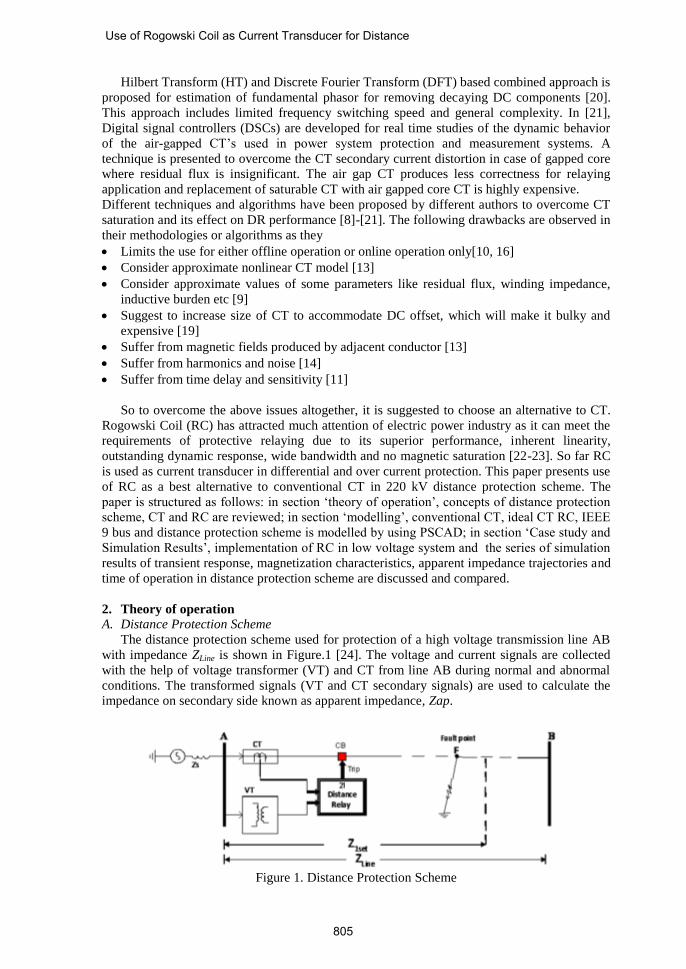
The distance protection scheme used for protection of a high voltage transmission line AB
with impedance ZLine is shown in Figure.1 [24]. The voltage and current signals are collected
with the help of voltage transformer (VT) and CT from line AB during normal and abnormal
conditions. The transformed signals (VT and CT secondary signals) are used to calculate the
impedance on secondary side known as apparent impedance, Zap.
Figure 1. Distance Protection Scheme
Use of Rogowski Coil as Current Transducer for Distance
805
The apparent impedance (Zap) and line impedance (ZLine(sec)) on secondary side, are given by
Eq.1 and Eq.2
𝑍𝑎𝑝 = 𝑉𝑇𝑆𝑒𝑐𝑜𝑛𝑑𝑎𝑟𝑦
𝐶𝑇𝑆𝑒𝑐𝑜𝑛𝑑𝑎𝑟𝑦 (1)
𝑍𝐿𝑖𝑛𝑒(𝑆𝑒𝑐) =𝐶𝑇𝑅
𝑉𝑇𝑅 𝑥 𝑍𝐿𝑖𝑛𝑒 (2)
Where, CTR and VTR are CT and VT ratios respectively.
Zone-1 setting, Z1set of DR used for protection of line AB is given by Eq.3
𝑍1𝑠𝑒𝑡 = 80% 𝑜𝑓 𝑍𝐿𝑖𝑛𝑒(𝑠𝑒𝑐) (3)
The DR compares Zap with Z1set to find the location of the fault, which may be inside or
outside the protected zone. The DR issues trip signal instantaneously if Zap ≤ Z1set and with
specified time delay if Zap> Z1set. Thus the signals received from VT and CT plays an
important role for correct and reliable operation of distance protection scheme.
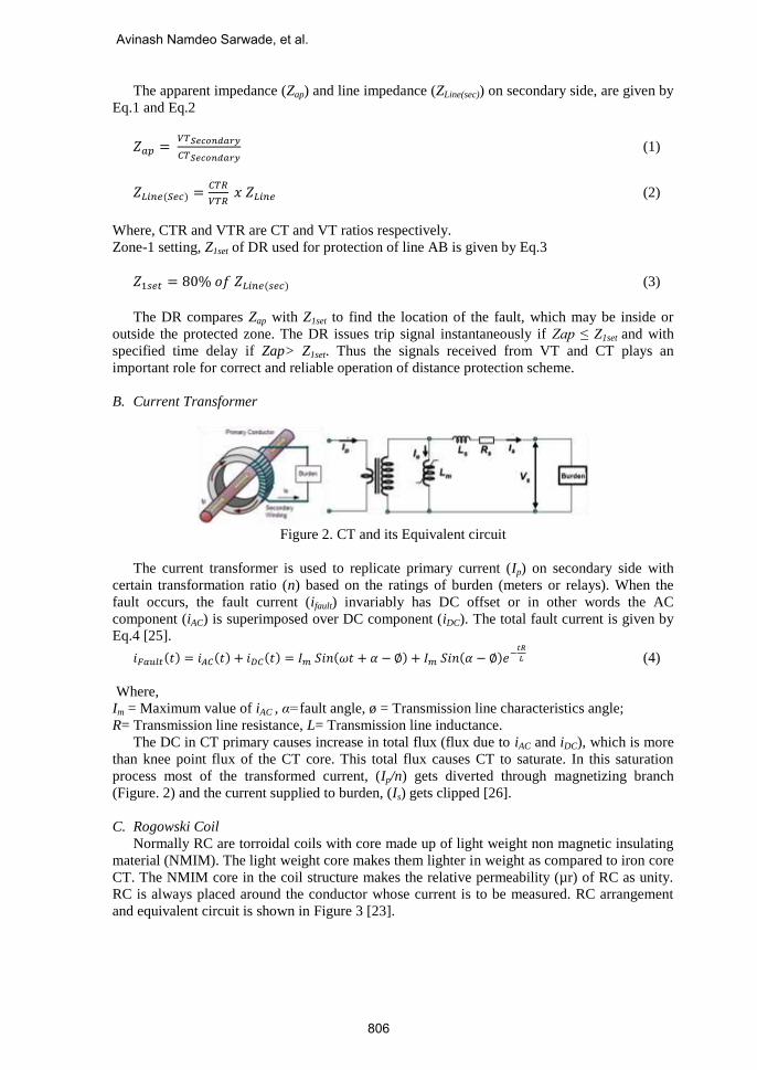
B. Current Transformer
Figure 2. CT and its Equivalent circuit
The current transformer is used to replicate primary current (Ip) on secondary side with
certain transformation ratio (n) based on the ratings of burden (meters or relays). When the
fault occurs, the fault current (ifault) invariably has DC offset or in other words the AC
component (iAC) is superimposed over DC component (iDC). The total fault current is given by
Eq.4 [25].
𝑖𝐹𝑎𝑢𝑙𝑡(𝑡) = 𝑖𝐴𝐶(𝑡) + 𝑖𝐷𝐶(𝑡) = 𝐼𝑚 𝑆𝑖𝑛(𝜔𝑡 + 𝛼 − ∅) + 𝐼𝑚 𝑆𝑖𝑛(𝛼 − ∅)𝑒−𝑡𝑅
𝐿 (4)
Where,
Im = Maximum value of iAC , α=fault angle, ø = Transmission line characteristics angle;
R= Transmission line resistance, L= Transmission line inductance.
The DC in CT primary causes increase in total flux (flux due to iAC and iDC), which is more
than knee point flux of the CT core. This total flux causes CT to saturate. In this saturation
process most of the transformed current, (Ip/n) gets diverted through magnetizing branch
(Figure. 2) and the current supplied to burden, (Is) gets clipped [26].
C. Rogowski Coil
Normally RC are torroidal coils with core made up of light weight non magnetic insulating
material (NMIM). The light weight core makes them lighter in weight as compared to iron core
CT. The NMIM core in the coil structure makes the relative permeability (µr) of RC as unity.
RC is always placed around the conductor whose current is to be measured. RC arrangement
and equivalent circuit is shown in Figure 3 [23].
Avinash Namdeo Sarwade, et al.
806

Figure 3. Rogowski coil and its equivalent circuit
The Voltage induced in the coil (Vrc(t)) by current ip(t) is given by Eq.5.
𝑉𝑟𝑐(𝑡) = −𝑀𝑑𝑖𝑝 (𝑡)
𝑑𝑡 (5)
Where, ip is the current which is to be sensed and M is the mutual coupling between
primary conductor and secondary winding [27].
The RC output voltage (Vout) in Laplace domain is given by Eq.6.
𝑉𝑜𝑢𝑡 = 𝑉𝑟𝑐[𝑍
𝑆2𝐿𝑠 𝑍 𝐶𝑠+𝑆(𝐿𝑠+𝑅𝑠 𝑍 𝐶𝑠)+(𝑅𝑠+𝑍)] (6)
D. Difference between Rogowski Coil and Coreless CT
Coreless CT can be called as air core CT. Rogowski coil (RC) basically uses a core made
up of NMIM such as plastic/epoxy/silicone rubber to support the secondary winding. This
NMIM also helps to provide galvanic isolation between primary and secondary. Silicone
rubber core makes RC flexible. Flexible Rogowski Coils are convenient for measuring electric
current in large or awkwardly shaped conductors, where space around the conductor is
restricted or where only a lightweight transducer can be suspended on the conductor. This
makes RC as ideal current transducer for retrofitting applications [28].
Coreless CT and Rogowski coil are non saturable instrument transformers which provide
linear characteristics over wide operating current range for normal and abnormal power system
conditions. But especially RC is designed in such a way to overcome the following issues
which may arise while dealing with coreless CT [22-23].
1. The relative position of the primary conductor inside the coil loop should not affect the coil
output signal.
2. The effect of electromagnetic field (cross-talk) produced by nearby conductors carrying
high currents on coil output signal should be minimal.
To satisfy the first condition, Mutual inductance M of RC must have a steady value for any
position of the primary conductor inside the coil loop. This can be achieved by
i. Providing a coil over a NMIM core with constant cross-section S (Figure. 4).
ii. Building a coil with constant turn density n (Figure. 4).
iii.
Figure 4. Rogowski coil and its construction
To satisfy the second condition, RC’s are designed with two wire loops connected in
electrically opposite directions. One or both loops can consist of wound wire. If only one loop
Use of Rogowski Coil as Current Transducer for Distance
807
is constructed as a winding, then the second wire loop can be constructed by returning the wire
through or near this winding (Figure. 4). If both loops are constructed as windings, then they
must be wound in opposite directions.
As the RC signal is a scaled time derivative of the primary current, signal processing is
required to extract the power frequency signal for phasor-based distance relays. This may be
achieved by integrating the RC output signals. The integrated signal accurately reproduces the
primary current waveform.
A unique RC feature to measure the speed of current change can be used for special protection
algorithms that would make decisions based on the change in the current slope instead on
current magnitude.
E. Disadvantages of RC
1. To achieve high accuracy, Rogowski Coils should be connected to devices that have
high input impedance.
2. Low sensitivity and requirement of shielding to avoid loss of signal
3. Temperature stability over wide operating current range
4. Integrator implementation
5. Low frequency noise magnification
6. Inability to drive multiple loads.
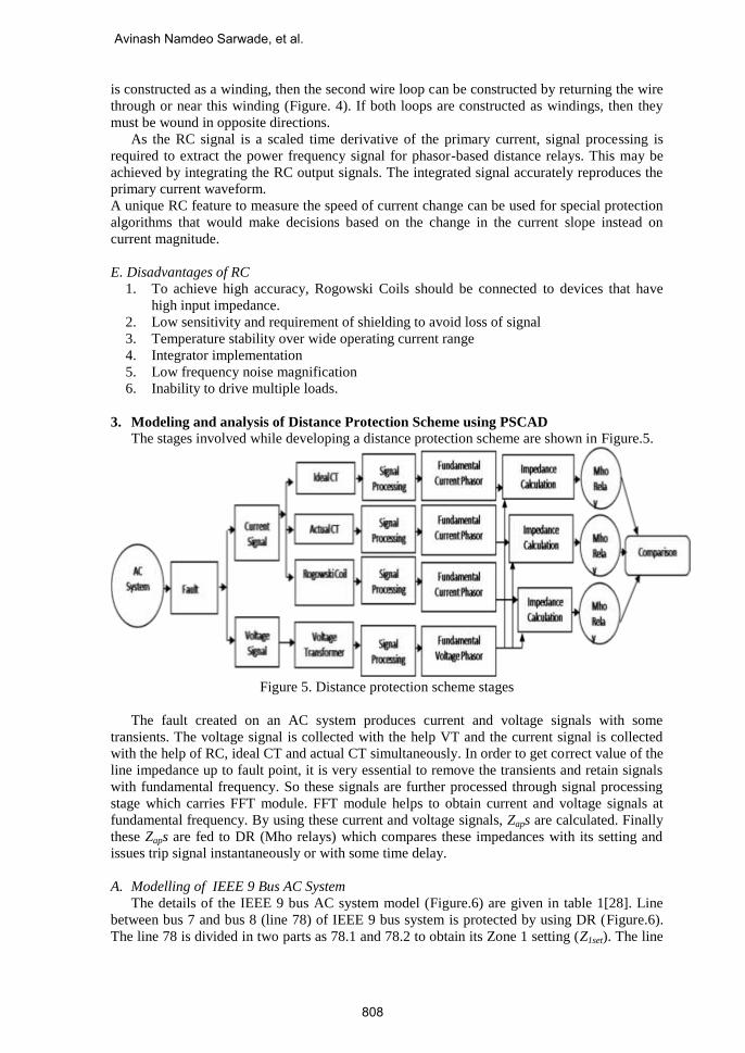
3. Modeling and analysis of Distance Protection Scheme using PSCAD
The stages involved while developing a distance protection scheme are shown in Figure.5.
Figure 5. Distance protection scheme stages
The fault created on an AC system produces current and voltage signals with some
transients. The voltage signal is collected with the help VT and the current signal is collected
with the help of RC, ideal CT and actual CT simultaneously. In order to get correct value of the
line impedance up to fault point, it is very essential to remove the transients and retain signals
with fundamental frequency. So these signals are further processed through signal processing
stage which carries FFT module. FFT module helps to obtain current and voltage signals at
fundamental frequency. By using these current and voltage signals, Zaps are calculated. Finally
these Zaps are fed to DR (Mho relays) which compares these impedances with its setting and
issues trip signal instantaneously or with some time delay.
A. Modelling of IEEE 9 Bus AC System
The details of the IEEE 9 bus AC system model (Figure.6) are given in table 1[28]. Line
between bus 7 and bus 8 (line 78) of IEEE 9 bus system is protected by using DR (Figure.6).
The line 78 is divided in two parts as 78.1 and 78.2 to obtain its Zone 1 setting (Z1set). The line
Avinash Namdeo Sarwade, et al.
808

lengths of these two parts can be varied to create a fault inside and outside of Z1set. Single line
to ground (SLG) fault is created with the help of time fault logic [29].
Figure 6. PSCAD model of IEEE 9 Bus AC system
Table 1. IEEE 9 Bus AC system details
Parameter Specifications
Generator 1 16.5 kV, 1.0098∠00 pu
Generator 2 18.0 kV, 1.0065∠5.13870 pu
Generator 3 13.8 kV, 1.0059∠1.547800 pu
3 Phase Transformer T1 16.5kV/220 kV, 100 MVA
3 Phase Transformer T2 18.0kV/220 kV, 100 MVA
3 Phase Transformer T3 13.8kV/220 kV, 100 MVA
Length of Line 78,89,57,69,45 & 46 100 km each
+Ve seq. impedance of transmission line (per km) 0.2928∠86.570 Ω
0 seq. Impedance of transmission line (per km) 1.102∠74.090 Ω
Load 1,2 &3 (125+j50), (90+j30), (100+j35) MVA
B. Modeling of Actual Current transformer
The actual CT with the following specifications is used (Figure. 7 & table 2) [30].
Figure 7. Actual CT Model
Table 2. CT Details
Parameter Specifications
CT ratio (CTR) 270/1
Secondary winding Resistance (Rs) 0.5 Ω
Secondary winding Reactance (Xs) 0.8mH
Magnetic Core Area 2.6x10⁻³ mm2
Magnetic Path Length 0.677mtr
CT Burden (Zb) (0.5+j0.251) Ω
Use of Rogowski Coil as Current Transducer for Distance
809

C. Modelling of Ideal Current Transformer
Figure 8. Ideal CT model
The primary current is divided by number of turns which have been considered in actual
current transformer, to get ideal value of secondary current (Figure. 8).
D. Modelling of Rogowski Coil
The RC module & integrator with the following specifications is used (Figure. 9 & table 3)
[31-32].
Figure 9. Rogowski Coil Model
Table 3. Rogowski Coil Details
Parameter Specifications Parameter Specifications
Mutual Inductance(M) 437.9 µH R of Integrator(Rint) 100 Ω
L of Rogowski Coil 0.118 mH C of Integrator(Cint) 1 µF
R of Rogowski Coil 0.113 Ω No of turns 270
C of Rogowski Coil 217 pF Output RMS 100mV/1 kA
Z of Rogowski Coil 5 k Ω Rated Current 100kA
4. Case study and Simulation Results
Using Eq. 2 and Eq. 3, Z1set of line 78 is given by Eq. 7.
𝑍1𝑠𝑒𝑡 = 0.135𝑥0.8𝑥100𝑥0.2928∠86.570 = 3.1617∠86.570Ω (7)
To observe the under reach phenomenon of the DR, line length of 78.1 is adjusted as 70 km
(Figure. 5).
After SLG fault, Zap is given by Eq.8.
𝑍𝑎𝑝 = 0.70𝑥0.135𝑥100𝑥0.2928∠86.570 = 2.76∠86.570Ω (8)
But due to external infeed from line 57 into bus 7, the actual impedance seen by the relay is
given by Eq. 9 [33].
𝑍𝑎𝑝𝑎𝑐𝑡𝑢𝑎𝑙 =𝐶𝑢𝑟𝑟𝑒𝑛𝑡 𝑤𝑖𝑡ℎ 𝑛𝑜 𝑖𝑛𝑓𝑒𝑒𝑑
𝐶𝑢𝑟𝑟𝑒𝑛𝑡 𝑤𝑖𝑡ℎ 𝑖𝑛𝑓𝑒𝑒𝑑𝑥𝑍𝑎𝑝(𝑆𝑒𝑐𝑜𝑛𝑑𝑎𝑟𝑦)
= 0.786𝑥2.96∠86.570 = 2.17∠86.570Ω (9)
Avinash Namdeo Sarwade, et al.
810
A. Impact of CT secondary burden
Burden connected to CT secondary is varied from 0.5 Ω to 10 Ω, to observe the effect of
CT saturation on secondary current, magnetization characteristics (B-H curve), Zap trajectories
and operating time of DR.
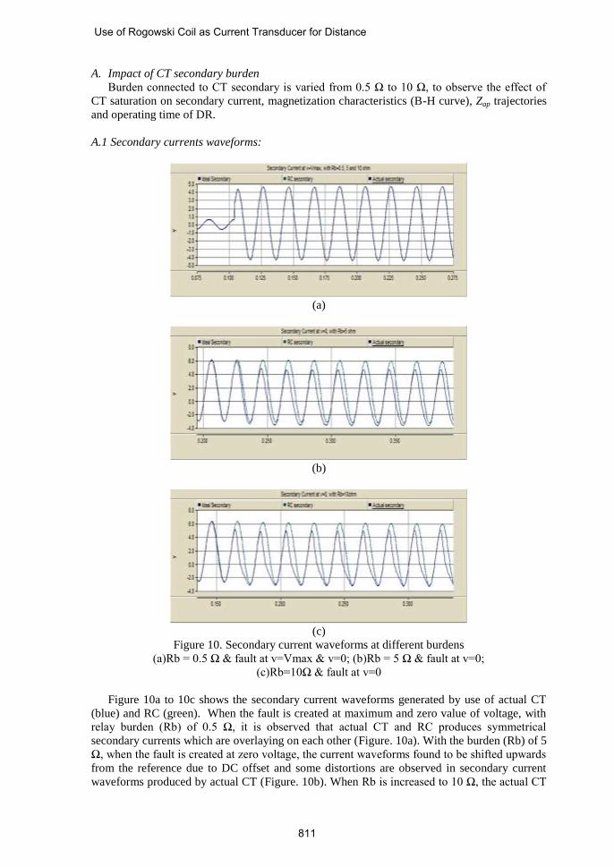
A.1 Secondary currents waveforms:
(a)
(b)
(c)
Figure 10. Secondary current waveforms at different burdens
(a)Rb = 0.5 Ω & fault at v=Vmax & v=0; (b)Rb = 5 Ω & fault at v=0;
(c)Rb=10Ω & fault at v=0
Figure 10a to 10c shows the secondary current waveforms generated by use of actual CT
(blue) and RC (green). When the fault is created at maximum and zero value of voltage, with
relay burden (Rb) of 0.5 Ω, it is observed that actual CT and RC produces symmetrical
secondary currents which are overlaying on each other (Figure. 10a). With the burden (Rb) of 5
Ω, when the fault is created at zero voltage, the current waveforms found to be shifted upwards
from the reference due to DC offset and some distortions are observed in secondary current
waveforms produced by actual CT (Figure. 10b). When Rb is increased to 10 Ω, the actual CT
Use of Rogowski Coil as Current Transducer for Distance
811

secondary waveform obtains more clipped and distorted shape (Figure. 10c). This proves that
even relative small burden can influence CT accuracy if the fault current is not correctly
anticipated.
To observe the performance of RC in DPS, different types of line to ground faults are
created at different burden at different fault inception positions, ie. v=0 and v=Vmax.
Table 4. Secondary currents at different CT burdens
Fault Instant v = Vmax v = 0
Relay Burden(Rb) 0.5Ω 0.5 Ω 5 Ω 10 Ω
Without CT (A) 3.48 3.48 3.48 3.48
With CT (A) 3.48 3.48 3.04 2.07
With Rogowski Coil (A) 3.48 3.48 3.48 3.48
Comparison of the secondary current root means square (rms) values at different burdens at
different fault instant are given by table 4. It is observed that rms value of the secondary
current produced by ideal CT and RC are approximately equal, but in case of actual CT it goes
on reducing with increase in burden.
A.2 B-H Curves of CT and Input-Output characteristics of RC
(a)
(b)
Avinash Namdeo Sarwade, et al.
812

(c)
Figure 11. B-H Curves with
(a)Rb = 0.5 Ω & fault at v=Vmax & v=0; (b)Rb = 5 Ω & fault at v=0;
(c)Rb=10Ω & fault at v=0
Figure 11a-11c shows, B-H curves generated by magnetization of actual CT and input-
output characteristics of RC. RC maintains its linearity of secondary current with respect to
primary current and found to be independent on fault instant and high value of connected
burden (Figure. 11a-11c). Actual CT gives linear B-H curve (Figure. 11a), when the fault is
created at Vmax & v=0 with CT burden as 0.5Ω. Saturated B-H curve of actual CT is
observed, when the burden is increased to 5 Ω (Figure. 11b). CT goes in deep saturation when
the burden is increased to 10 Ω (Figure. 11c).
After CT saturation, it is observed that, increase in CT burden increases magnetizing force
required to produce same amount of flux density (Table 5).
Table 5. B & H parameters at last saturation point with different burdens
Secondary Burden
Instant of Fault v =Vmax v = 0
Rb (Relay Burden) 0.5Ω 0.5 Ω 5 Ω 10 Ω
B (Wb/m2) 0.019 0.069 1.92 1.92
H (AT/m) 0.475 1.90 1464 2035
A.3 V-I Characteristics of Rogowski coil (Case Study)
Rogowski coil which was installed in Gujarat state for Induction heating purpose is shown
in Figure. 12 [34-35].
Figure 12. Installation of Rogowski coil for Induction heating application
Use of Rogowski Coil as Current Transducer for Distance
813
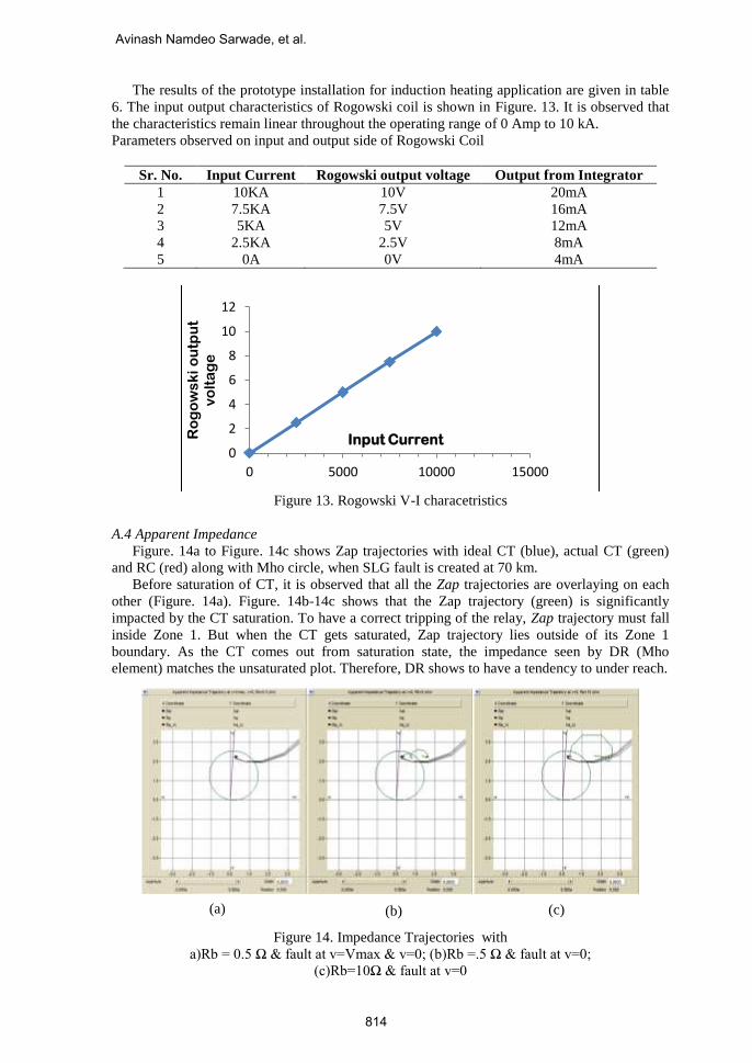
The results of the prototype installation for induction heating application are given in table
6. The input output characteristics of Rogowski coil is shown in Figure. 13. It is observed that
the characteristics remain linear throughout the operating range of 0 Amp to 10 kA.
Parameters observed on input and output side of Rogowski Coil
Sr. No. Input Current Rogowski output voltage Output from Integrator
1 10KA 10V 20mA
2 7.5KA 7.5V 16mA
3 5KA 5V 12mA
4 2.5KA 2.5V 8mA
5 0A 0V 4mA
Figure 13. Rogowski V-I characetristics
A.4 Apparent Impedance
Figure. 14a to Figure. 14c shows Zap trajectories with ideal CT (blue), actual CT (green)
and RC (red) along with Mho circle, when SLG fault is created at 70 km.
Before saturation of CT, it is observed that all the Zap trajectories are overlaying on each
other (Figure. 14a). Figure. 14b-14c shows that the Zap trajectory (green) is significantly
impacted by the CT saturation. To have a correct tripping of the relay, Zap trajectory must fall
inside Zone 1. But when the CT gets saturated, Zap trajectory lies outside of its Zone 1
boundary. As the CT comes out from saturation state, the impedance seen by DR (Mho
element) matches the unsaturated plot. Therefore, DR shows to have a tendency to under reach.
Figure 14. Impedance Trajectories with
a)Rb = 0.5 Ω & fault at v=Vmax & v=0; (b)Rb =.5 Ω & fault at v=0;
(c)Rb=10Ω & fault at v=0
0
2
4
6
8
10
12
0 5000 10000 15000
Ro
go
ws
ki
ou
tpu
t v
olt
ag
e
Input Current
(a) (b) (c)
Avinash Namdeo Sarwade, et al.
814
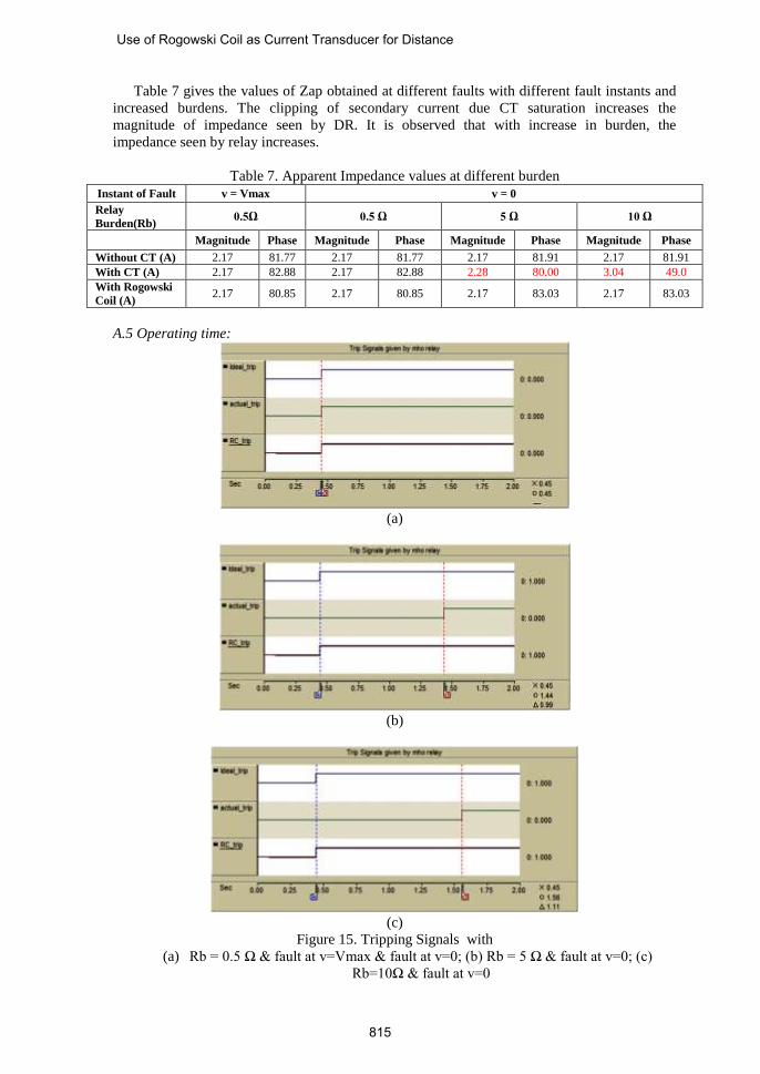
Table 7 gives the values of Zap obtained at different faults with different fault instants and
increased burdens. The clipping of secondary current due CT saturation increases the
magnitude of impedance seen by DR. It is observed that with increase in burden, the
impedance seen by relay increases.
Table 7. Apparent Impedance values at different burden
Instant of Fault v = Vmax v = 0
Relay
Burden(Rb) 0.5Ω 0.5 Ω 5 Ω 10 Ω
Magnitude Phase Magnitude Phase Magnitude Phase Magnitude Phase
Without CT (A) 2.17 81.77 2.17 81.77 2.17 81.91 2.17 81.91
With CT (A) 2.17 82.88 2.17 82.88 2.28 80.00 3.04 49.0
With Rogowski
Coil (A) 2.17 80.85 2.17 80.85 2.17 83.03 2.17 83.03
A.5 Operating time:
(a)
(b)
(c)
Figure 15. Tripping Signals with
(a) Rb = 0.5 Ω & fault at v=Vmax & fault at v=0; (b) Rb = 5 Ω & fault at v=0; (c)
Rb=10Ω & fault at v=0
Use of Rogowski Coil as Current Transducer for Distance
815

The operating time of a DR (Mho relay) is considerable to make sure of high speed
tripping. Before CT saturation, all Mho relay elements issues their tripping signals at same
instant (Figure. 15a-15b). When CT burden is increased from 2.5 Ω to10Ω, CT goes in deep
saturation. This CT saturation process causes the Zap to lie outside Zone1 for some time and to
return back inside zone1 when CT comes out of saturation. It delays Mho relay element
operation connected to actual CT and result in slower than expected tripping times (Figure.
15c-15e).
Table 8. Tripping Times at Different Burdens
Tripping Time
Fault Instant v =Vmax, v=0 v = 0
Relay Burden 0.5Ω 5 Ω 10 Ω
Without CT Instantaneous Instantaneous Instantaneous
With CT Instantaneous After 0.99 S After 1.11 S
With RC Instantaneous Instantaneous Instantaneous
Table 8 gives the time required for MDR to operate, when the burden is increased from 0.5-
10Ω. It is observed that increase in CT burden, increases the magnitude of the Zap, causing
delay in the time of operation.
5. Conclusion
Low voltage case study and PSCAD simulations shows superiority of RC as current
transducer over conventional iron core CT. Increased CT secondary burden (0.5-10 Ω) and
presence of dc offset in fault current causes a CT to produce a highly distorted and clipped
secondary current. Distortion reduces effective value of secondary current. The problem
becomes more critical when fault takes place near to the boundary of first zone of Distance
Relay (DR). In this situation the DR observes this fault in its second zone for initial 10 cycles
of current waveform. This fault re-enters in first zone when secondary current regains its
original shape. Ideally this fault needs to be attempted instantaneously. This can cause the DR
to under reach and trip after a longer period of time than it was originally anticipated.
Rogowski coil produces exact replication of primary current without distorting it with any load
burden and prevent DR from under reach phenomenon.
6. References
[1]. Stanley H. Horowitz, Arun G. Phadke, “Power System Relaying”, John Wiley & Sons
Ltd, ISBN: 978-0-470-05712-4, Third Edition, 2008.
[2]. “Protection Application Handbook”, ABB, BA THS / BU Transmission Systems and
Substations
[3]. “ Instrument Transformer Application Guide”, ABB, High Voltage Products
[4]. Walter A. Elmore, “Pilot Protective Relaying”, ABB Automation and Marcer Dekker
Inc., ISBN:0-8247-8195-3, Year:2000.
[5]. IEEE Power Engineering Society, “IEEE Standard Requirements for Instrument
Transformers-IEEE Std C57.13™-2008”, The Institute of Electrical and Electronics
Engineers, Inc., July 2008.
[6]. Piotr Sawko, “Impact of Secondary Burden and X/R Ratio on CT Saturation” Wroclaw
University of Technology, Faculty of Electrical Engineering, 2008:1-3.
[zet10.ipee.pwr.wroc.pl]
[7]. Pentti Mahonen, Vesa Virtanen, Tapio Hakola, “The Rogowski coil and the voltage
divider in power system protection and monitoring”, ABB Transmit and substation Oy,
Vaasa, Finland
[8]. A.Wiszniewski; J.Szafran,“Distance digital algorithm immune to saturation of current tra
nsformers”, Fourth International Conference on Developments in Power Protection,
1989:196 – 199.
Avinash Namdeo Sarwade, et al.
816

[9]. Y. C. Kang J. K. Park ; S. H. Kang ; A. T. Johns ; R. K. Aggarwal, “An algorithm for
compensating secondary currents of current transformers”, IEEE Transaction on Power
Delivery, 1997;12:116-124, DOI: 10.1109/61.568231
[10]. S.. Bittanti, F. A. Cuzzola, F. Lorito, and G. Poncia, “Compensation of nonlinearities in a
current transformer for the reconstruction of the primary current,” IEEE Trans. Control
Sys. Technol., vol. 9, no. 4, pp. 565–573, Jul. 2001. DOI:10.1109/87.930967
[11]. J. Pan, K. Vu, and Y. Hu, “An efficient compensation algorithm for current transformer
saturation effects,” IEEE Trans. Power Del., vol. 19, no. 4, pp. 1623–1628, Oct. 2004.
DOI: 10.1109/TPWRD.2004.835273
[12]. Hyun-Woong Lee; Yong-Cheol Kang; Sung-Il Jang; Yong-Gyun Kim,
“Distance relay suitable for use with a measurement type current transformer” IEEE
Conference on Power Tech, 2007: 1176 -1181, DOI: 10.1109/PCT.2007.4538482
[13]. Ferry A. Viawan; Jianping Wang; Zhao Wang; Winnary-Ying Yang, “ Effect of current
sensor technology on distance protection”, IEEE/PES Power Systems Conference and
Exposition, 15th -18th March 2009:1-7, DOI: 10.1109/PSCE.2009.4840177
[14]. B. Ajaei, M. Sanaye-Pasand, M. Davarpanah, A. Rezaei-Zare, and R. Iravani,
“Compensation of the current-transformer saturation effects for digital relays,” IEEE
Trans. Power Del., vol. 26, no. 4, pp. 2531–2540, Oct. 2011.
DOI:10.1109/TPWRD.2011.2161622
[15]. Soumya R. Mohanty, V. Ravikumar Pandi, B.K. Panigrahi, Nand Kishor, Prakash K. Ray,
“Performance Evaluation of Distance Relay with CT saturation”, Elsevier Journal of
Applied Soft Computing, December 2011;11(8): 4789-4797,
DOI:10.1016/j.asoc.2011.07.003
[16]. Sinisa J. Zubic, Milenko B. Djuric, “A distance relay algorithm based on the phase
comparison principle:, Electric Power Systems Research, November 2012;98:20-28, DOI:
10.1016/j.epsr.2012.05.017
[17]. A. Hooshyar and M. Sanaye-Pasand, “Accurate measurement of fault currents
contaminated with decaying dc offset and ct saturation,” IEEETrans. Power Del., vol. 27,
no. 2, pp. 773–783, Apr. 2012. DOI: 10.1109/TPWRD.2011.2176965
[18]. M. Moghimi Haji, B. Vahidi, S.H. Hosseinian, “Current Transformer Saturation
Detection Using Gaussian Mixture Models”, Journal of Applied Research and
Technology, February 2013;11(1):79–87, DOI: 10.1016/S1665-6423(13)71516-5
[19]. Hector J.Altuve, Normann Fischer, Gabriel Benmouyal, Dale Finney,
“Sizing current transformers for line protection applications”, 66th Annual Conference
on Protective Relay Engineers, 2013: 36 - 51, DOI: 10.1109/CPRE.2013.6822025.
[20]. Mohsen Tajdinian, Mehdi Zareian Jahromi, Kazem Mohseni, Shahram Montaser
Kouhsari, “An analytical approach for removal of decaying DC component considering
frequency deviation”, Electric Power Systems Research, January 2016;130:208-219,
DOI:10.1016/j.epsr.2015.09.007.
[21]. F.A. Pereira, F.C.F. Guerra, B.A. Sousa, E.N.A. Santos, N.S.D. Brito, U.A. Carmo, “Real
time compensation algorithm for air-gapped current transformers saturation effects”,
Electric Power Systems Research, online availability on 7th April 2016,
DOI:10.1016/j.epsr.2016.03.035
[22]. IEEE PSRC report, “Practical Aspects of Rogowski Coil Applications to Relaying”,
Power System Relaying Committee of the IEEE Power Engineering Society, September
2010:1-72, http://www.pes-
src.org/Reports/Practical%20Aspects%20of%20Rogowski%20Coil%20Applications%20t
o%20Relaying_Final.pdf
[23]. Veselin Skendzic and Bob Hughes, Schweitzer Engineering Laboratories, Inc. “Using
Rogowski Coils Inside Protective Relays”, 66th Annual Conference for Protective Relay
Engineers College Station, Texas, 8th -11th April 2013,
DOI:10.1109/CPRE.2013.6822022
Use of Rogowski Coil as Current Transducer for Distance
817

[24]. Avinash N. Sarwade, Pradeep K. Katti andJayant G. Ghodekar, “Optimum Setting of
Distance Protection Scheme for HV Transmission Line”, Journal of Power Electronics
and Power Systems, STM, 2013;3(2):23-30.
[25]. Paithankar Y.G., S.R. Bhide, “Fundamentals of Power System Protection”, PHI Learning
Pvt Ltd, ISBN: 8120341236, 97881203412342010, 2010
[26]. Lecture Notes- NPTEL, “Electrical Engineering-Power Sytem Protection”, 2009, Chapter
7
[27]. Sudha, K.R. Valluvan, T. Basavraju, “ Fault Diagnosis of Transmission Lines with
Rogowski Coils as Current Sensors”, International Journal of Computer Applications,
May 2013;70(25):19-25, [research.ijcaonline.org
[28]. Power System simulation software, “PSCAD/EMTDC 4.2.1”, Manitoba HVDC Research
Centre Inc., Canada, 2008
[29]. Hongyan Teng, Chongru Liu ; Minxiao Han ; Shiying Ma ; Xiaojiang Guo, “IEEE9 Buses
System Simulation and Modeling using PSCAD” Asia-Pacific Power and Energy
Engineering Conference, 28th-31st March 2010: 1-4, DOI:
10.1109/APPEEC.2010.5448242
[30]. Dharshana Muthumuni, Lisa Ruchkall, and Dr. Rohitha Jayasinghe, “Modelling Current
Transformer saturation for detailed Protection studies”, Pulse Newletter, Manitoba HVDC
Research Centre, Dec. 2011:1-4,
https://hvdc.ca/uploads/ck/files/newsletters/Pulse_Dec2011.pdf
[31]. Fulufhelo Andrew Netshiongolwe and John Michael van Coller, “Electrical Stress
Monitoring of Distribution Transformers using Bushing Embedded Capacitive Voltage
Dividers and Rogowski Coils”, Proceeding of International conference on Power System
Transients-56, 15th -18th June 2015:1-8,
http://www.ipstconf.org/papers/Proc_IPST2015/15IPST056.pdf
[32]. Murtaza Hashmi and Matti Lehtonen, “Effect of Rogowski coil and covered conductor
parameters on the performance of PD measurements in Overhead distribution Networks”,
16th PSCC, Glasgow, Scotland, 14th -18th July 2008:1-7
[33]. Juan M. Gers, Edward J. Holmes, Chapter 9, “Distance Protection”, Protection of
Electricity Distribution Networks, The Institution of Engineering and Technlogy Power
and Energy Series-47, 2nd Edition, 2004:173-223.
[34]. Ashish S. Paramane, Avinash N. Sarwade, Pradeep K. Katti and Jayant G. Ghodekar,
“Rogowski Coil - A Novel Transducer for Current Measurement”, 6th International
Conference on Power System Protection and Automation, CBIP, New Delhi, India, 27th -
28th February 2014:80-88.
[35]. Datasheet, “MFC-150-Flexible Rogowski Coil”, 1DAUMFC15004, Algodue Electronica,
Italy.
Avinash Namdeo Sarwade, et al.
818

Avinash Namdeo Sarwade received his bachelor degree in Electrical
Engineering from Walchand College of Engineering, Sangali, Shivaji
University, Kolhapur, in 1998 and M. Tech (Power System) from College of
Engineering Pune, University of Pune in 2006. Presently he is pursuing Ph. D
from Dr. Babasaheb Ambedkar Technological University, Lonere and
working as faculty member in Sinhgad College of Engineering, Pune. His
area of research is Power System Protection.
Pradeep K. Katti received his Bachelor degree in Electrical Engineering
from Bapuji Institute of Engineering and Technology, Davanagere, Mysore
University’s in 1985, M.E. (Control System) from College of Engineering
Pune, University of Pune in 1991 and Ph. D in Energy system from
Visvesvaraya National Institute of Technology, Nagpur in 2007. He has a
wide teaching experience and presently working as Professor in Department
of Electrical Engineering, Dr. Babasaheb Ambedkar Technological
University, Lonere, India. He has a large no. of publications in National and
International Journals on his credit. His area of research is Renewable Energy.
Jayant G. K. Ghodekar received his Bachelor and Masters degree in
Electrical Engineering from College of Engineering Pune, University of Pune
in 1964 & 1975 respectively and Ph. D in Control system from IIT Delhi in
1985. He has a large no. of publications in National and International
Journals on his credit. His area of research is Control System.
Use of Rogowski Coil as Current Transducer for Distance
819