use of ground penetrating radar to review mn roads marc loken office of materials and road research...
TRANSCRIPT

Use of Ground Penetrating Radar to Review MN Roads
Marc LokenMarc Loken
Office of Materials and Road Office of Materials and Road ResearchResearch
Tel: 651-779-5526Tel: 651-779-5526
[email protected]@dot.state.mn.us
Minnesota Department of Minnesota Department of TransportationTransportation
Mn/DOTOffice of Materials and Road Research

Outline
Applications of GPRApplications of GPR Basic Principles of GPRBasic Principles of GPR MnDOT GPR EquipmentMnDOT GPR Equipment Current ProjectsCurrent Projects Future ProjectsFuture Projects ConclusionsConclusions

• Determine pavement thickness
• Calculate material properties
• Detect subsurface anomalies
• Determine depth to bedrock
• Detect stripping and/or layer separation
• Analyze rutting mechanisms
• Detect subsurface moisture and/or freezing
Applications of GPR

Basic Principles of GPR

Typical Data Scan

Material Characterization Dielectric Constant
The dielectric constant of a material is its ability to store electrical energy

Dielectric Constants of Some Common Materials
MaterialMaterial εεii
AirAir 1.01.0
AsphaltAsphalt 3-53-5
ConcreteConcrete 4-114-11
GraniteGranite 4-74-7
ShaleShale 5-155-15
WaterWater 8181
MetalMetal InfinityInfinity

Dielectric Constant Calculation
1= [(1+ρ1)/(1- ρ1)]2
where: 1= dielectric constant of surface layer
1 = A1 / Am
A1 = amplitude of the surface
reflection from the surface layer Am = amplitude of the surface
reflection from metal sheet

Calculation of Layer Thickness2*h1 = c t1 / 1
where: h1 = thickness of 1st layer
c = speed of radar in air
= 11.8 in/ns
t1 = time required to transmit signal
through 1st layer

MnDOT GPR Equipment Data Collection SystemsData Collection Systems
SIR 2000SIR 2000 SIR 020SIR 020
AntennaAntenna 100 MHz (5 to 20 ft depth)100 MHz (5 to 20 ft depth) 400 MHz (2 to 10 ft depth)400 MHz (2 to 10 ft depth) 1 GHz (Air-Coupled) (0 to 4 ft depth)1 GHz (Air-Coupled) (0 to 4 ft depth) 1.5 GHz (0 to 3 ft depth)1.5 GHz (0 to 3 ft depth)
Post-Processing SoftwarePost-Processing Software RADAN NTRADAN NT RoadDoctor (tenatative)RoadDoctor (tenatative)

Equipment – SIR 020

Equipment – Van & Antenna

Current Projects
MnROAD – Calibration, Rutting, Layer Thickness, MnROAD – Calibration, Rutting, Layer Thickness, Material IdentificationMaterial Identification
Olmsted CR 117 – Ground Truth Measurements, Layer Olmsted CR 117 – Ground Truth Measurements, Layer ThicknessThickness
TH 212 – Subsurface Cracks, Pavement Layer TH 212 – Subsurface Cracks, Pavement Layer IdentificationIdentification
TH 22 – Evaluate Pavement Thickness, Road StructureTH 22 – Evaluate Pavement Thickness, Road Structure TH 7 – Stripping Layers and Interface SeparationTH 7 – Stripping Layers and Interface Separation

MnROAD
ObjectivesObjectives CalibrationCalibration Layer ThicknessLayer Thickness Material IdentificationMaterial Identification
Pavement StructurePavement Structure Cells 33-35Cells 33-35
4” Asphalt4” Asphalt 12” Class 612” Class 6
Cell 36Cell 36 6 1/4” Concrete6 1/4” Concrete 5” Class 55” Class 5

MnROAD -- Calibration

MnROAD -- Calibration
Cell 33

MnROAD – Layer Thickness
Cell 34

MnROAD – Material ID
Cell 36

Olmsted CR 117
ObjectivesObjectives Ground Truth MeasurementsGround Truth Measurements Layer ThicknessLayer Thickness
Pavement StructurePavement Structure 6” Asphalt6” Asphalt 12” Class 512” Class 5

Olmsted CR 117
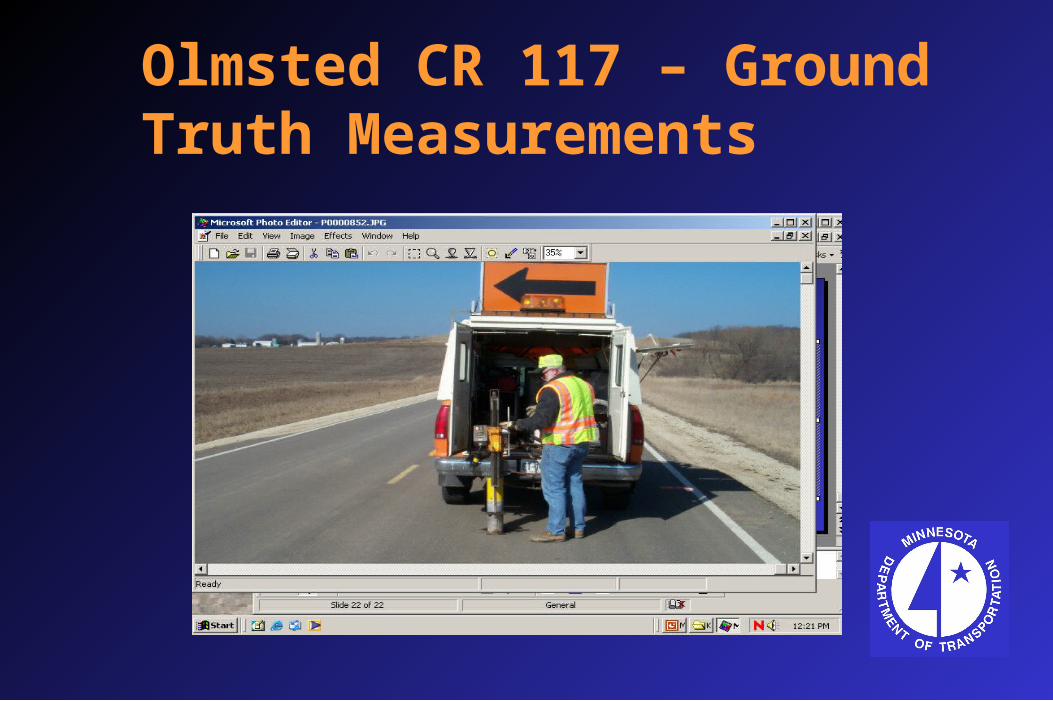
Olmsted CR 117 – Ground Truth Measurements

Olmsted CR 117 – Layer Thickness
Station 130+00

TH 212
ObjectivesObjectives Subsurface CracksSubsurface Cracks Pavement Layer IdentificationPavement Layer Identification
Pavement StructurePavement Structure 9-10” Asphalt9-10” Asphalt 13-14” Gravel Base13-14” Gravel Base Concrete or Clay Loam SubgradeConcrete or Clay Loam Subgrade

TH 212 – Subsurface Cracks
Mile 118.4

TH 212 – Clay Loam
Mile 118.0

TH 212 – Concrete
Mile 118.4

TH 22
ObjectivesObjectives Pavement ThicknessPavement Thickness Road StructureRoad Structure
Pavement Structure Pavement Structure 3-6” Asphalt3-6” Asphalt Concrete or Gravel BaseConcrete or Gravel Base

TH 22 – Pavement Thickness
Greeley Ave

TH 22 – Material Identification
Ford Ave

TH 7
ObjectivesObjectives Stripping LayersStripping Layers Interface SeparationInterface Separation
Pavement StructurePavement Structure 10-12” Asphalt10-12” Asphalt 12-36” Gravel12-36” Gravel

TH 7 – Interface Separation
Mile 152.6

Future Projects
MnROAD (Rutting Mechanisms)MnROAD (Rutting Mechanisms) Pine Co. (Stripping and Overlay History)Pine Co. (Stripping and Overlay History) St. Louis County (Depth to Bedrock)St. Louis County (Depth to Bedrock) TH 55 (Fault Plane Survey)TH 55 (Fault Plane Survey) Interstate Park (Potholes in Bedrock)Interstate Park (Potholes in Bedrock)

Conclusions
GPR is nondestructive field test used to GPR is nondestructive field test used to determine road structuredetermine road structure
GPR utilizes high-speed data collection at GPR utilizes high-speed data collection at speeds up to 50 mph speeds up to 50 mph
Gives a continuous subsurface Gives a continuous subsurface descriptiondescription
GPR can be used to identify subsurface GPR can be used to identify subsurface structures up to 20 ft in depthstructures up to 20 ft in depth