use of gasket parameters as a average emission … · average emission factor method ... of the...
TRANSCRIPT

Standards
Certification
Education & Training
Publishing
Conferences & Exhibits
Use of Gasket Parameters as a Reasonable Alternative to the Average Emission Factor Method for Estimating Fugitive Emissions from Flanged Connectors
14th LDAR Symposium May 19 – 21, 2014 New Orleans, LA

2
Presenter
Dale Rice has over 25 years of engineering and consulting experience in the environmental field, and is currently an environmental engineer with VSP Technologies. He is responsible for coordinating and supporting efforts to assist customers in meeting their environmental requirements with the products and technologies that VSP supplies. Mr. Rice has key focus areas: fugitive emissions associated with gasket leakage, corporate sustainability, and environmental compliance regulations. He holds a B.A. in Chemistry from Hope College and a M.S. in Environmental Engineering from Syracuse University. Mr. Rice is a registered Professional Engineer and resides with his wife, Susan in greater Wilmington, North Carolina.

Significance of Fugitive Emissions
3
Air Emissions as Reported for the Toxic Release Inventory (All industries, HAPs, U.S. , 2012)

Sources of Fugitive Emissions at a Chemical Plant
4
Source: “Leak Detection and Repair – A Best Practices Guide”, USEPA
31%
62%
7%

Our Focus Today: Connectors
5
31%

Specifically: Bolted Flanged Connectors
6
Flanged
X

Why Only Bolted Flanged Connectors?
7
BFCs Use Gaskets Test Coefficients Available for Many Gaskets Gasket Coefficients Can Be Used to Predict Emission Rates Predicted Emission Rates Can Be Used (Potentially) for Some Environmental Reporting

Room Temperature Test (ROTT)
8

PVRC Empirical Method
9
Tp = (Sg/Gb)(1/a) < Tpmax (unitless) [Eq. 1] Sf = r (η Sg – P (Ai/Ac)) (psi) [Eq. 2] kf= log (η Sg/Gs) / log Tp (unitless) [Eq. 3] Tf= (Sf/Gs)(1/kf) < Tpmax
(unitless) [Eq. 4] Lr= [(P/14.7)(1/Tf)]2 / 150 (mg / sec /mm) [Eq. 5] Ltot = Lr d (3600)(25.4)(1x10⁻⁶) (kg/hr) [Eq. 6]
Empirical tools used to estimate the leakage rate1:
1 Rice, Dale and Waterland, Jerry, “Environmental Considerations for Gasket Selection and the Development of an Emissions Calculator for Gasket Materials”, PVP2014-28024, Proceedings of the ASME 2014 Pressure Vessels & Piping Conference, July 20-24, 2014, Anaheim, CA (To Be Published.)

Fugitive Emissions Calculator
10
The “FEC” requires the following data: • Number and NPS of connectors • Operational pressure • Annual hours of operation • Percent of chemical in process stream(s) • Published emission factor(s) • ROTT data for selected gasket materials

PVRC Empirical Method
11
The FEC calculated leakage rate has a built-in conservative factor: ROTT data are based on the leakage rates for helium. Therefore, the FEC leakage rate for all other fluids (except hydrogen) is actually lower than calculated.

PVRC Empirical Method
12
The FEC is based on the premise that the user has an identified Gasket-Use Process Management Program at the site (or process unit level), which which will ensure that all procedures for proper connector installation and maintenance are in place.
Confidential Test Facility
13
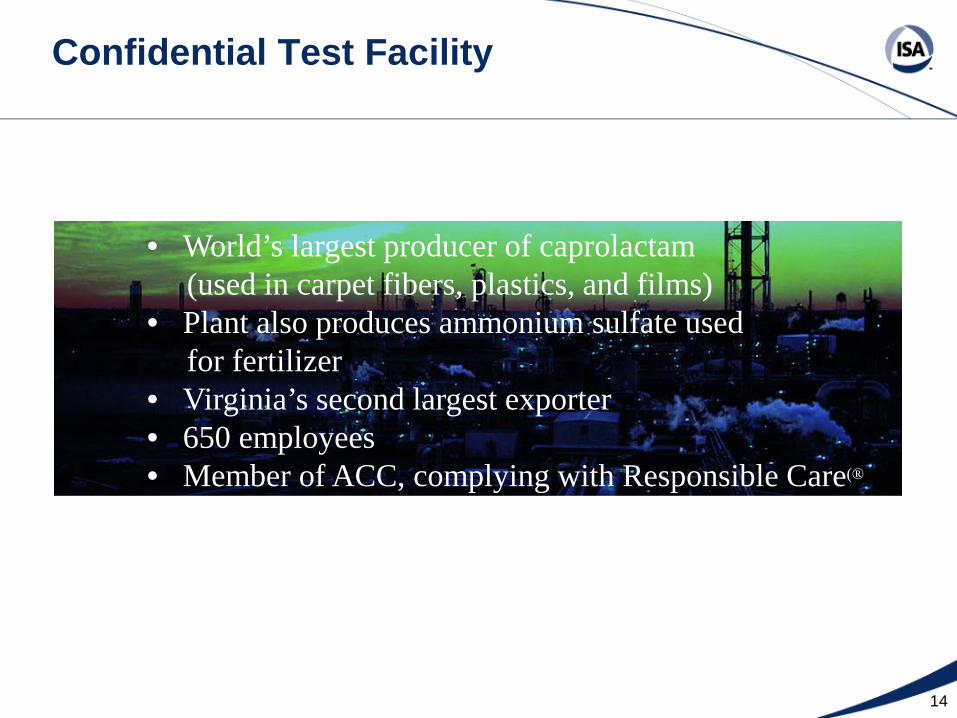
Confidential Test Facility
14
• World’s largest producer of caprolactam (used in carpet fibers, plastics, and films) • Plant also produces ammonium sulfate used for fertilizer • Virginia’s second largest exporter • 650 employees • Member of ACC, complying with Responsible Care(®

Confidential Test Facility
15
Flanged
X Test Process Area (Toluene): Total Connectors: 744 Flanged: 413 (56%)

Fugitive Emissions Calculator
16
Inputs:
Name of Facility: HoneywellFacility Contact: Jan KountzChemical Name: TolueneData Year: 2013Name of Process 1 Area X Toluene
No. Connectors (Enter Any Integer) 400% Annual Hrs Operated (Enter 1 - 100) 100
% Process Stream (Enter 1 - 100) 100Emission Factor Used (Number in lbs/hr/connect.) 0.00004Operational Pressure (Number in psi) 50
Name of Process 2 Area X Recycled TolueneNo. Connectors (Enter Any Integer) 13
% Annual Hrs Operated (Enter 1 - 100) 100% Process Stream (Enter 1 - 100) 85
Emission Factor Used (Number in lbs/hr/connect.) 0.00004Operational Pressure (Number in psi) 50

Fugitive Emissions Calculator
17
Inputs:
2
6
46
49
58
Click here to compare fugitive emissions calculations:(Calculates total combined emissions for all process areas).
Select Gasket Materials to Compare:
Emissions

Facility Name:Chemical:Data Year:
Process Area(s):
Connector Count
Assumed Annual Hrs. of
Operation
Assumed Operating Pressure
(psig)
Chemical Percent of
Process Stream
Chemical Emissions
Amt (lbs/yr)
Avg Emissions / Connector
(lbs/yr)Area X Toluene 400 8760 50 100% 140.16 0.350Area X Recycle Toluene 13 8760 50 85% 3.87 0.298
0 0 0 0% 00 0 0 0% 0
Totals 413 144.03
HoneywellToluene
Published Emissions Factor (PEF) Calculations2013
18
Fugitive Emissions Calculator
Outputs: Each process area is calculated separately.

19
Fugitive Emissions Calculator
Outputs:
Calculated Total Emissions for All Gasketed Connectors (Compared to PEF)
Calculation Using Published Emission Factor 144.0
57
3192
84
1 - Flexible graphite on corrugated metal - Brand 1
5 - Kammprofile - with Flexible Graphite Facing
4 - Laminated Graphite w/ SS Insert
3 - Reinforced Graphite Sheet
2 - Flexible graphite on corrugated metal - Brand 2
Total Emissions (lbs/yr)2.8
3.9

20
Fugitive Emissions Calculator
Outputs:
PEF
1 2
3
4
5

21
Fugitive Emissions Calculator
Outputs:
PEF
1 2
3
4
5
Test Facility

22
Fugitive Emissions Calculator
Test Facility: Estimated 2013 Toluene Fugitive Emissions Published Emission Factor Approach: 260 Pounds Using Partial* FEC Approach: 169 Pounds
91 Pound / Yr Reduction!
* 413 flanged connectors using FEC and 331 non-flanged using PEF

23
Fugitive Emissions Calculator
So why is there a major difference between the two
approaches?

24
Fugitive Emissions Calculator
So why is there a major difference between the two
approaches? Published emission factors: 1. Are based on averaged monitoring results at a
number of different facilities.

25
Fugitive Emissions Calculator
So why is there a major difference between the two
approaches? Published emission factors: 1. Are based on averaged monitoring results at a
number of different facilities. 2. Assume “once size fits all” – each NPS uses
the same emission rate!

26
Comparing FEC with PEF Estimates
24 in OD
NPS
Published Emission Factor
Approach (lbs toluene/yr)
Fugitive Emissions Calculator
(lbs toluene/yr)
1 in OD
0.35
0.35
0.009
10.1

27
Fugitive Emissions Calculator
So why is there a major difference between the two
approaches? Published emission factors: 1. Are based on averaged monitoring results at a
number of different facilities. 2. Assume “once size fits all” – each NPS uses
the same emission rate! 3. Do not distinguish between gasket materials
being used.

28
Fugitive Emissions Calculator
However, FEC results are a function of: 1. Operating pressure 2. Connector diameter 3. Gasket material used 4. In-service gasket mechanical stability
Conclusions
29
1. The FEC offers a reasonable alternative to the traditional published emissions factor approach. The FEC accounts for several important factors that are not included with the emission factor approach.
2. The published emission factor method results are often overly conservative. 3. To be fully credible, the FEC method should be backed by a defined gasket-use process management program at the site or process unit level, to ensure consistent input/design conditions.
