use of dynamic simulation for design, validation and ... 2014/prezentari_sesiuni_plenare... · use...
TRANSCRIPT

Use of Dynamic Simulation for Design, Validation and Training for
New and Existing Nuclear Reactors
August 6, 2013
Thomas Carlsson, GSE Power Systems

2
Agenda
• Introductions
• GSE Overview Presentation
• What is a Simulator? Real-Time, Engineering…
• Bringing in Engineering Analysis Codes in GSE Real Time Simulation Platform
• DesignEP – Severe Accident Analysis Simulator
• Risk-Informed Predicitive Simulator

3
Introductions
• Speaker name: Thomas Carlsson
• Speaker Title: Managing Director
• GSE Power Systems AB
• Location: Nyköping, Sweden
4
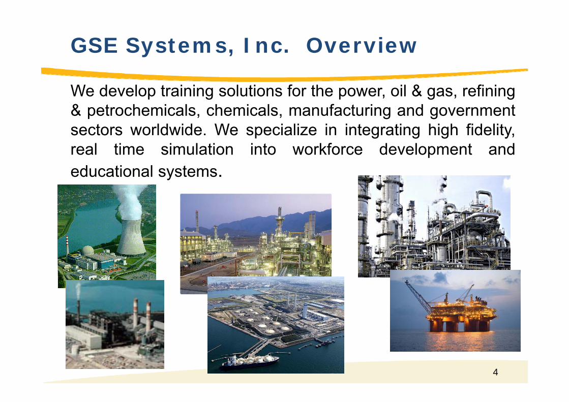
GSE Systems, Inc. Overview
We develop training solutions for the power, oil & gas, refining& petrochemicals, chemicals, manufacturing and governmentsectors worldwide. We specialize in integrating high fidelity,real time simulation into workforce development andeducational systems.

5
Company Profile
Markets Largest company in the world focused on simulation World leader in advanced simulations solutions and training programs World leader in Power Simulation Vertical Markets: Nuclear, Fossil, Refining, Oil & Gas, Petrochemicals, Chemicals Over 1,100 Installations, 160 Customers, 50+ Countries
Size Founded in 1929, IPO in 1994 Headquarters in Sykesville (Baltimore) Maryland ~240 employees in 8 locations in 5 countries JV Simulation companies in Russia, GSE-RUS Annual Revenue $50M+
Relevance to our customers Culture of working with customer to solve problems Strong Project Management Process & On-Time Delivery record Depth of Staff and Breadth of Knowledge so No Single Point of Failure (Risk
Mitigation)
O&G Refinery
Fossil -Coal
NuclearPower
Training Centers
Training Technolog
y

6
Americas
ArgentinaBrazilCanadaChileMexicoPuerto RicoUnited StatesVenezuela
Europe
BelgiumBulgariaCzech RepublicDenmark FinlandFranceGermanyItalyKazakhstanNorway
Africa / Middle East
AlgeriaAngolaEgyptLibyaNigeriaOmanPakistanQatarSaudi ArabiaSouth AfricaUnited Arab Emirates
Global Reach
PolandRussiaSlovakiaSpainSwedenSwitzerlandThe NetherlandsUkraineUnited Kingdom
Asia / Pacific
AustraliaChinaIndiaIndonesiaJapanKoreaMalaysiaSingaporeTaiwanTurkmenistanPhilippinesPapua New Guinea
US Offices- (HQ) Baltimore, MD- St. Mary’s, GA- Cary, NC- Madison, NJ
Nyköping, Sweden
Beijing, China
Chennai, India
Stockton on Tees, UK
Glasgow, UK

7
• 65% Installed Base
• Experience with the Major NSSS Vendors:Westinghouse GE SiemensABB/CE Babcock & Wilcox Chinese #1 InstitutePBMR RosEnergo NuScaleMitsubishi Toshiba Hitachi
• Experience with the Major DCSsEmerson Ovation & Delta V ABB Symphony & x800AGE Mark V & Mark VI Siemens TXP and T3000Honeywell Experion & TDC3000 Invensys Foxboro IA & A2
PLCs
• Member of ANS 3.5 Standards Committee
GSE Role in Nuclear Market

8
Relevant Experience
• Fossil DCS Upgrades (Virtual Commissioning)
• Experience with First-of-a-Kind Projects– Westinghouse AP1000– Pebble Bed Modular Reactor– NuScale Power– mPower– B&W– Ultra-Supercritical– Royal Navy
Simulator Score CardPressurized Water Reactor 85Boiling Water Reactor 60
Fossil Fuel Plant 118Process Plant 84
Graphite Moderated Reactor 8Advanced Gas Reactors 4
Major Mods, Rehost, Upgrades 125

9
Full Scope Nuclear Simulator Projects
9
ProjectsSanmen AP1000 China FSS with WEC Translated Ovation DCS
Haiyang AP1000 China FSS with WEC Translated Ovation DCS
Vogtle AP1000 US FSS with WEC Translated Ovation DCS
Scana AP1000 US FSS with WEC Translated Ovation DCS
Haiyang #2 AP1000 China FSS with GSE Simulated Ovation DCS (100% GSE)
Mochovce U3/4 VVER440 Slovak FSS with Stimulated Siemens T2000 and HW Panels
*KSG D46 PWR Germany FSS with Traditional HW Panels/IOs
*NuScale SMR US FSS w/o DCS (Control created using GSE JADE tools)
*mPower B&W SMR US FSS just started (V&V for DCS and HMI)
CNPEC DCS V&V Platform China DCS V&V Platform for Chinese New CPR1000
*Tsuruga U2 PWR Japan FSS with Traditional HW Panels/IOs
*Tokai U2 BWR Japan FSS with Traditional HW Panels/IOs
JMTR Research Reactor Japan Experimental field of neutron for nuclear material R&D
* Means customer provides engineers working with GSE

10
FSS Mod/Upgrade/Eng. Services Projects
10
ProjectsD.C. Cook 2nd PWR US New Simulator for U1 and Upgrade Simulator U2
Laguna Verde BWR Mexico Upgrade BOP and Turbine Control models
KSU R1 BWR Sweden Upgrade Primary Systems (RELAP5-HD & S3R)
KSU O1 Sweden Upgrade Primary Systems (RELAP5-HD & S3R)
KSU R2 Sweden Upgrade Primary Systems (RELAP5-HD & S3R)
KSG D3 Germany Rehost to Linux and TH Upgrades to RELAP5-HD & S3RKSG S2 Germany Rehost to Linux and TH Upgrades to RELAP5-HD & S3RHeysham II (AGR) UK Upgrade Entire Simulator models
Kozloduy VVER1000 Bulgaria Upgrade Primary Systems (RELAP5-HD & Core)
Mulhebulg BWR Switzland Upgrade TH Systems (RELAP5-HD & S3R)
Exelon Fleet US Eng. Service Agreement for 9 Simulators
KSU Fleet Sweden Eng. Support for 8 Simulators
KSG Fleet Germany Eng. Support for 5 Simulators
US NRC US Shoreham Sim Rehost & Upgrade & RELAP5-HD & DCS HMIUS NRC US GPWR for HMI StudyUS Navy US BETTIS & KAPL Simulator Tools & Eng. Services

11
What is a Simulator??

12
What is a Simulator??

13
• Definition– 1st Principles Models– Conservation of energy, mass, & momentum– Dynamic Response through Full Range of Operations – Network solution for pressure and flow versus sequential solution– Variable malfunctions (i.e., range of severity, ramping, delaying)– Can fail any Component (pump, transmitter, valve, motor etc.)
• Why Its Important– Simulator needs to faithfully represent real plant for
• optimization studies,
• evaluation of plant modifications, and
• validation of new control systems
• Cover full range of operations
– Simulator must be predictive
High Fidelity Dynamic Simulation

14
• Training– Plant Operator Training, Qualification and Certification– Realistic Operating Experience for Managers, Engineers and
Maintenance Personnel
• Design– Verify and Validate New Plant and Digital Control System
Designs– Perform Human-Machine Interface Studies to Optimize New
Control Room Arrangements– Test Design Changes Before they are Implemented
• Operations– Provide Test Environment for Plant Operating Procedures
Development and Validation– Optimize Plant Operating Conditions
Objectives of Purchasing Simulators

15
Real-Time Dynamic Simulators
• What is a Dynamic, Real-Time, or Engineering simulator?

16
• Broad or Full Scope Plant Model– Include primary, secondary, BOP and Safety system and at
least a High Fidelity Main Loop
• All models Integrated and Synchronized (coupling)
• 1 second of problem time equal 1 second of real time (feels like the real plant)
• Models are interactive – Observe and operate like the real plant– Can be integrated with real control systems
Real-Time Simulator

17
• Holistic Engineering V&V platform• Validation of system design issue in integrated “Plant”
• Controls System Design & V&V• Validation and Refinement of Logic and Controls Strategies • As a development tool for new control strategies
• Human Factors Engineering Platform• Support design of DCS interface, alarms, procedures, etc.• Support design of digital control rooms, information layout
Demonstrate viability of these designs to Regulator
• Develop and Validate Operating Procedures
• Post Fukushima Challenges
Role of the “Engineering” Simulator
17

18
GSE First of a Kind/Engineering Simulator Experience
18
Pebble Bed Modular Reactor
SinopecIGCC China
Westinghouse AP1000NuScale Power Ultra Supercritical
Korea
CNPDCHYH CPR-1000 HFE and Control V&V Platfrom
B&WmPowerEngineering and HFESimulator
FutureGen Alliance OxyCoal Engineering Simulator

19
Example – Westinghouse AP1000
• Project Objectives/Deliverable – To provide an Integrated First-Principle
High Fidelity Simulator Models (Actual Plant is being designed) for:
• Human Factors Engineering (HFE)• I&C / DCS Validation and Testing
(Stimulated DCS)• Train Westinghouse Staff on use of
simulation technology
• Major Project Achievements– 12 months Project Schedule (Initial
Phase) - On Time Delivery– Communication Interfaces between
SimExec and Ovation DCS– Developed and V&V the plant system
models synchronize with plant design schedule
• Project Status– Complete all 3 phases of
implementation– Building 4 full scope simulators for
Westinghouse• Project Duration
– November 2004 to November 2006
19
Initial Control Room Layout
Most Recent Control Room Layout

20
• Current NRC requirements do not accommodate the next generation SMR control room designs– Requirements for large reactors
need to be evaluated for their appropriateness to SMR operations.
– Current requirements interfere with the economic model of some SMRs
Example – New SMR (NuScale)
20#

21
The Dynamic Simulator will be the platform for both the development and demonstrationof this new plant design
HFE Platform for the new Control Room DesignControl System Design and V&V PlatformSystem Design Validation PlatformMarketing Tool!Training (Critical path to Plant Operation)
Background
21#

22
Big Problem and a Solution
• Plant design data is changing or does not exist yet.– We can develop first cut models for unfinished
systems quickly and provide feed back to designers
– With enough data, control design can begin in an agile rapid prototyping approach
– Plant operational procedures can be investigated early
– …

23
Control logic and interface Design
23#
Engineers develop controls & logic, basic control screens and operating procedures
– JControl– JDesigner
System Design Data is validated on high fidelity models
– Steady state and transient conditions
– System performance is fed back to system design engineers via JStation

24
HFE Simulator (Control Room)
HFE Simulator 12 Modules plus common systems 12 RELAP5, S3R, etc. 12 Operator Stations
Engineering Simulator 1 Module 1 RELAP5, S3R, stc.

25
• Reduce Project Risk– Continuously validate system designs early in design process
• Steady State• Validated in integrated and transient conditions
– Provide a platform for validation of DCS system – Provide a demonstration platform for Regulators and
Customers of plant operation and safety• Reduce Project Costs
– Provide platform continuous development of control and protection logic strategies on lower cost simulation platform
– Flexible lower cost HFE/Control Room development platform– Delay commitment to a DCS vendor until the sale of the plant,
allow customer to choose DCS vendor– Refine Alarm Management and plant procedures
• High definition training simulator for free
Engineering Simulator Value

26
Bringing Engineering Analysis Codes into Real-time Full Scope Simulators
June 20, 2013

27
• Running 3rd Party Best Estimate or Safety Analysis codes as integral parts of full scope simulators
• Enforce synchronization between multiple systems through client and server architecture
• Maintain integrity of original code
• Ensure repeatability • Allow users to have access to model internal
memory and variables
• Advanced 2D, 3D visualization interfaces
GSE High Definition (HD) Platform

28
GSE HD Platform Architecture
output
input
Client
Simulator Host Executive (GSE or non-GSE)
HD Client Executive #1 Server
Client C Module
Server input/outputStatus request
control
Customized Plug-in
interface Client
Standard HD Server
Configuration

29
Multiple HD Servers
GSE or Other
Simulator
HD Client
HD Server #1
HD Server #2
HD Server #3
HD Server #n
BWR configuration• Server #1 (CPU#1): RELAP for
BWR Vessel
• Server #2 (CPU#2): Neutron Kinetics Code (ex. REMARK)
PWR configuration• Server #1 (CPU#1): RELAP for
primary loops
• Server #2 (CPU#2): RELAP for steam generators
• Server #3 (CPU#3) Neutron Kinetics Code (ex. REMARK)
SMR configuration
•Server #1 (CPU#1): RELAP for module #1•Server #2 (CPU#2): RELAP for module #2•Server #3 (CPU#3): S3R for module #1•Server #4 (CPU#4): S3R for module #2•----

30
• Servers may include GSE or 3rd party models, e.g.,• GSE’s Topmeret, REMARK
• MAAP5, MAAP4,
• INL’s RELAP5-3D v2.4, v4.0x
• Studsvik’s S3R (neutronics) and Thermal Margin codes
• MELCOR
• SPICE – analog circuit board
• Russian VVER Neutronic modes
• GOTHIC etc..
• Flexible configuration –• Multiple computers, • Multiple processors/cores, • Varied frame rates
Extensible Platform

31
RELAP5-HD InstallationsReactor Type Country Status
BWR, GE Japan RFTPWR, WE United States On-goingPWR, WE United States On-goingPWR, WE United States On-goingSmall Modular Reactor, B&W United States On-goingPWR, WE United States On-goingCANDU Canada RFTPWR, RUS Ukraine On-goingNaval Reactor UK On-goingPWR, WE Netherlands On-goingBWR, GE United States RFTSmall Modular Reactor, NuScale
United States RFT
PWR, WE South Korea RFTPWR, WE South Korea RFTPWR, CE South Korea RFTPWR, WE South Korea RFTPWR, ASEA Germany RFTPWR, ASEA Germany RFTBWR, ASEA Germany RFTPWR, ASEA Germany RFTBWR, ASEA Sweden RFTBWR, ASEA Sweden RFTBWR, ABB Sweden RFTBWR, GE Switzerland RFTPWR, RUS Bulgaria RFTPWR, RUS Ukraine RFTJMTR Japan RFTPWR, WE Japan RFTBWR, GE Japan RFT
RELAP5-3D requires US DOE export license

32
MAAP4 & 5 Installations
Reactor Type Plants, Country StatusBWR, GE K5, Japan MAAP 3.0, 1994
MAAP 4.0, 20133-Loop PWR, WE KTN2, Japan MAAP4, 20064-Loop PWR, WE (ice condenser)
KON1, Japan MAAP4, 2006
BWR, GE TK2, Japan MAAP 3.0, 1998 MAAP 4.0, 2013
BWR, GE 2F2, Japan MAAP3, 2001BWR, GE TS1, Japan
(Same design as 1F1)MAAP3, 1997
4-Loop, PWR, Mitsubishi
TS2, Japan MAAP 3.0, 1998MAAP 4.0, 2013
PWR, WE R2, Sweden MAAP5, RFTPWR, WE United States MAAP5, On-goingPWR, WE United States MAAP5, On-going
MAAP code requires US EPRI user license

33
GSE SYSTEMS DESIGNEP–ADVANCED MODELING & ANALYSIS
PROBLEM SOLUTION
New requirements • Models beyond design basis accident scenarios for SAMG/EDMG
• Simulates parallel events in multiple units• Interfaces with plant dose model to project offsite dose• Conducts “what-if” analysis of actions and consequences
New drills and resource strain
• Uses time and resources more efficiently in analysis of scenarios as well as development, validation, and verification of procedures and guidelines
• Enhances performance and depth of understanding in training, drills, and exercises
Limitations of current tools/sims
• Provides graphical depictions to understand dynamic phenomena
Close alignment of EP/Ops/Trng/etc.
• Compatible with both BWR and PWR• Lowers costs and improves agility

34
DESIGNEP FOR FUKUSHIMA MULTI-UNITACCIDENTS
• Used MAAP code as analytical and modeling tool • Developed in collaboration with EPRI and ERIN Engineering• Can also use MELCOR code

35
FUKUSHIMA UNIT 3 AT 76 HOURS

36
FUKUSHIMA UNIT 3 CONTAINMENT AT 76 HOURS

37
OFF-SITE RADIOLOGICAL DOSE (MAAP)
Time 6H:20M:45S

38
STATION BLACKOUT MITIGATION STRATEGYUSING DESIGNEP(MAAP5) FOR EXCELON
Time 6H:20M:45S

39
Graphical SAMGs
Computer-based Procedures that helps to automate the SAMG to control the sequence-of-events in PSA-HD simulation.

40
WHY DESIGNEP
• GSE Systems’ DesignEP™ is available now
• Cost Effective
• Scalable
• Based on EPRI’s MAAP Code or NRC MELCOR

41
Progressive Simulator Solutions
DesktopSimulator
Full Scope Simulator
Risk-informed Simulator
Desktop HD (MAAP or RELAP)
HD (MAAP, RELAP, JADE,
etc..)
HD (MAAP, RELAP, JADE, Uncertainty, Database, etc..)

42
Risk-informed Predictive Simulation

43
• Physical Engine– To mimic the Nuclear Power Plant;– Real-time full-scope simulator, integral test facility or research reactor;– Allow external events & operator interventions;– Feed current plant configuration & condition to Decision Engine.
• Decision Engine– Dynamic Event Tree (DET) that evolves with physical engine;– Minimize the paths in DET based on probability & risk;– Automated generation of calculation engine inputs;– Automated termination and restart calculation engine based on given
criteria;– Pre-processing to reduce dimensions of data;– Analyze the risk & probability for future transient;– Post-processing to obtain concise & risk-informed prediction for
decision-making.
Risk-informed Predictive Simulation

44
• Calculation Engine– Much faster than real-time simulation with acceptable fidelity;– Parallel/cluster computation;– Seamless and flexibility on restart;– Database that manages calculation data for easy & fast access.
• Risk-informed Display GUI– Concisely display the risk of future transient;– Best-estimate future scenario;– Risk should be defined with probability and uncertainty;– Optimized operation procedure/guideline.
Risk-informed Predictive Simulation

45
QUESTIONS
Thomas CarlssonMD
GSE Power Systems, Sweden
45
46
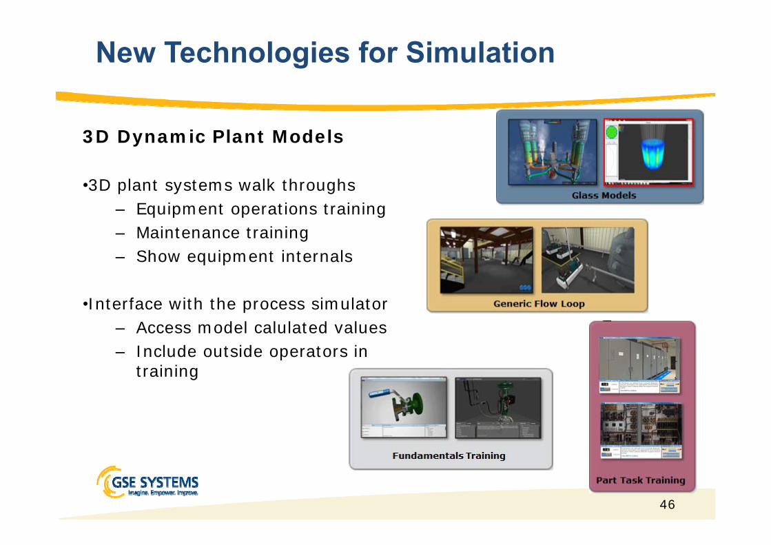
3D Dynamic Plant Models
•3D plant systems walk throughs– Equipment operations training– Maintenance training– Show equipment internals
•Interface with the process simulator– Access model calulated values– Include outside operators in
training
New Technologies for Simulation

47
MAAP
Data Centric System
MAAP4.06
MAAP4.08
MAAP5.01
MAAP5.02
MAAP5.03
RELAP5-3D

48
V&V Tool
49
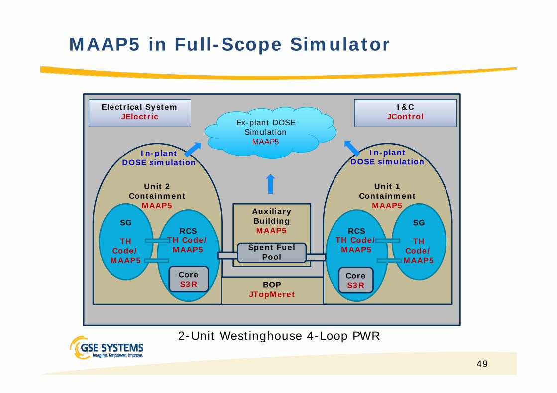
2-Unit Westinghouse 4-Loop PWR
MAAP5 in Full-Scope Simulator
Unit 2Containment
MAAP5
RCS TH Code/
MAAP5
SG
TH Code/MAAP5
CoreS3R
Unit 1Containment
MAAP5
RCS TH Code/
MAAP5
SG
TH Code/ MAAP5
CoreS3R
In-plant DOSE simulation
In-plant DOSE simulation
Ex-plant DOSE Simulation
MAAP5
BOPJTopMeret
Auxiliary BuildingMAAP5
Spent Fuel Pool
I&CJControl
Electrical SystemJElectric

50
MAAP5 in Full-scope Simulator
Timeline 0 Min. ~60 Min.3 Hrs. 20
Min.5 Hrs. 30
Min.
Scenario Steady-stateLOCA, code
transition
LOCA, Core melt-down
LOCA, Vessel failed
MAAP Server #1
Unit #1 RCS/SG
TH CodeTransition
MAAP5.0
Unit #1 Containment
MAAP5.0
MAAP Server #2
Shared Aux. Building(w/ SFP)
MAAP5.0
SimulatorBOP GSE JTopmeret
Neutronics Studsvik S3R MAAP5.0