use and maintenance manual compact - nuvair · use and maintenance manual quick guide warning -...
TRANSCRIPT
w w w . a e r o t e c n i c a c o l t r i . c o m
MCH 8-11/EM CompactMCH 13-16/ET Compact
MCH 26-32/ET CompactMCH 13-16-18/ET Compact Evo
MCH 13-16/ET Compact MMCH 16/EM Compact E1
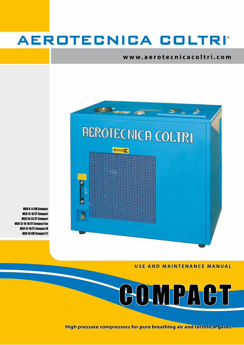
U S E A N D M A I N T E N A N C E M A N U A L
C O M PA C THigh pressure compressors for pure breathing air and technical gases


pag. 3 di 66COMPACT
Via Colli Storici, 17725010 SAN MARTINO DELLA BATTAGLIA (BS) ITALY
Tel. +39 030 9910301 Fax. +39 030 9910283www.coltrisub.it www.coltrisub.com
Use and Maintenance Manual
HIGH PRESSURE COMPRESSORS FOR PURE BREATHING AIR AND TECHNICAL GASES
MCH 8-11/EM CompactMCH 13-16/ET CompactMCH 26-32/ET Compact
MCH 13-16-18/ET Compact EvoMCH 13-16/ET Compact M
MCH 16/EM Compact E1
BEFORE USING THE COMPRESSOR READ THIS MANUAL CAREFULLY
IMPORTANT

pag. 4 di 66 COMPACT Use and Maintenance Manual
Dear Customer,Thank you for choosing an AEROTECNICA COLTRI compressor. This manual isprovided together with the compressor to aid you in the use of the machine and ensure that your work produces the best possible results.
Please read all the instructions and information provided on the following pages. Ensure that the manual is at the disposal of the personnel who will be using/managing thecompressor and carrying out any maintenance on it.
Should you require any clarification, when using the compressor for the first time or at anyother time it is used, please remember that AEROTECNICA COLTRI is at yourcomplete disposal.
Should you need to contact us our fax number is: +39 030 9910283
For routine or unscheduled maintenance note that AEROTECNICA COLTRI international technical service is able to provide you with assistance and spare parts as and whenrequired.
To ensure that your requests are dealt quickly, the following information is provided:
Manufacturer’s data: AEROTECNICA COLTRI SpA. Via Colli Storici, 177 25010 SAN MARTINO DELLA BATTAGLIA (BRESCIA) - ITALY Tel +39 030 9910301 - +39 030 9910297 Fax +39 030 9910283 http://www.coltrisub.it - http://www.coltrisub.com e-mail: [email protected]

pag. 5 di 66COMPACTUse and Maintenance Manual
DECLARATION CONFORMITYItalian DPR 459 of 24 th July 1996, appendix II, part A
It is hereby declared that he machine model:
MCH 8-11/EM Compact
MCH 13-16/ET Compact
MCH 26-32/ET Compact
MCH 13-16-18/ET Compact Evo
MCH 13-16/ET Compact M
MCH 16/EM Compact E1
Serial n° year
complies with
the provisions of Italian DPR 459/96 as per EEC directives 89/392, 93/44 and 93/68according to the specifications of the following harmonized standards:
EN 292-1 (‘91) - EN 292-2 (‘91) - EN 60204-1 (‘92) - ISO 3746 - ISO 11202
and also complies with
the provisions of Italian Dlgs 476/92 as per EEC directives 89/336 and 92/31 according to the specifications of the following harmonized industrial environment standards:
EN 50081-2 (August 1993)EN 50082-2 (March 1995)
DESENZANO DEL GARDA, date
Chairman of the Board of Directors Carlo Coltri
This manual is the property of AEROTECNICA COLTRI SpA. Reproduction, whole or partial, is forbidden

pag. 6 di 66 COMPACT
A C
A C
A C
A C
AC CA
AC
1
1
34
5
5 2
2
A
PRESSOSTATO
PRESSURE
SWITCH
MANOMETRO
3° STADIO
PRESSURE GAUGE
3° STAGE
230 Volt
ATTENZIONE
CONTROLLARE IL LIVELLO DELL’OLIO
OGNI 50 ORE E SOSTITUIRLO OGNI
250 ORE DI LAVORO
WARNING
CHECK OIL LEVEL EVERY 50 HOURS
AND CHANGE OIL EVERY
250 WORKING HOURS
SCARICO OLIO
OIL DRAIN
890mm - 35”
850m
m -
33”
600m
m -
23”
B
ATTENZIONE
CONTROLLARE IL LIVELLO DELL’OLIO
OGNI 50 ORE E SOSTITUIRLO OGNI
250 ORE DI LAVORO
WARNING
CHECK OIL LEVEL EVERY 50 HOURS
AND CHANGE OIL EVERY
250 WORKING HOURS
SCARICO OLIO
OIL DRAIN
890mm - 35”
840m
m -
33”
600m
m -
23”
PRESSOSTATO
PRESSURE
SWITCH
MANOMETRO
3° STADIO
PRESSURE GAUGE
3° STAGE
AEROTECNICA COLTRI S.r.l.
230 Volt
TESTPURGE
ONOFF
B
890mm - 35”
840m
m -
33”
600m
m -
23”
PRESSOSTATO
PRESSURE
SWITCH
MANOMETRO
1° STADIO
PRESSURE GAUGE
1° STAGE
MANOMETRO
2° STADIO
PRESSURE GAUGE
2° STAGE
MANOMETRO
3° STADIO
PRESSURE GAUGE
3° STAGE
AEROTECNICA COLTRI S.r.l.
230 Volt
TESTPURGE
ON OFFLOW
LEVELOIL
WRONGROTATION
ATTENZIONE
CONTROLLARE IL LIVELLO DELL’OLIO
OGNI 50 ORE E SOSTITUIRLO OGNI
250 ORE DI LAVORO
WARNING
CHECK OIL LEVEL EVERY 50 HOURS
AND CHANGE OIL EVERY
250 WORKING HOURS
SCARICO OLIO
OIL DRAIN
B
Use and Maintenance Manual
Quick guide
WARNING - This guide is intended only as a rapid introduction to use of the compressor.- This guide is not meant to replace the use and maintenance manual.- This compressor must not be used before reading the entire use and maintenance manual.
QUICK GUIDE
Preliminary tasks:- Position the compressor in the selected area (see chap
“5”)- If necessary connect the air intake extension (see section
“5.3.2”).- Check the oil level; if the compressor is new fill the oil
sump with the oil supplied with the compressor (see section “7.6”).
- Connect the electric motor to the mains power socket (see section “5.3.3”);
- For compressors equipped with a three-phase electric motor, check that the cooling fan rotates in the direction indicated by the arrow on the cover; if it turns the other way invert two of the three phases on the mains power (see section “6.1.2”).
- Connect up the refill hoses (see section “7.12”).- Check the safety valve is working (see section “7.8”);- Check that compressor shutdown pressure is the same
as the pressure set on the pressure switch (See Chap.“6.4.”);
Bottle refill (see section “6.6”):- fit the hose connector 1 on the bottle connector 3
(closed) (A);- open the condensate discharge valve 2 and bottle
valve 4;- start the compressor (B);Once refilling has been completed wait for automatic shutdown of the compressor with the pressure switch:- close filling valve 2 and tank valve 4 (A);- bleed the pressure from the filling valve via the bleed
valve 5 (A);- disconnect the connector 1 from the bottle (A).
Maintenance:- After the first 50 working hours change the oil again (see
section “7.6.3”).- Check the lubricating oil level every 5 hours (see section
“7.6.2”).- Change the lubricating oil every 250 hours (see section
“7.6.3”).- Periodically change the air intake filter (see section
“7.7”).- Check the safety valve at every refill (see section “7.8”).- Check transmission belt tension and if necessary change
them (see section “7.10”).- Discharge the condensate (see section “7.9”).- Periodically replace the active carbon filters / molecular
sieve (see section “7.11”).- Periodically replace the refill hoses (see section “7.12”).
Model: Compact M
Model: Compact
Model: Compact Evo
Emergency
Stop
Start
Start
Emergency
Stop
Emergency
Start
Stop

pag. 7 di 66COMPACTUse and Maintenance Manual
Contents
CONTENTSCHAPTER 1 – GENERAL 10 1.1 Preliminary information 10 1.2 Required operator training 10 1.3 Important information for the user 11 1.4 Foreword 12 1.5 Warranty 12 1.6 Assistance 13 1.7 Responsibility 13 1.8 Purpose of the machine 14 1.9 Where the machine may be used 16 1.10 Running in and testing the compressor 16 1.10.1 Tightening torque values 16
CHAPTER 2 – BASIC INFORMATION ON THE COMPRESSOR 17 2.1 Description of the compressor 17 2.2Identificationthecompressor 17 2.3 General instructions 18
CHAPTER 3 – SAFETY REGULATIONS 19 3.1 General safety rules 19 3.1.1 Know the machine 19 3.1.2 Protective clothing 19 3.1.3 Emergency equipment 19 3.1.4 Checks and maintenance 19 3.2 General precautions 20 3.2.1 Important safety information 21 3.2.2 Accident prevention 21 3.2.3 Working safety 21 3.2.4 Noise level 21 3.2.5 Residual risk zones 22 3.3 Safety info labels: location 23 3.3.1 Safety info labels: description 24 3.4 General safety regulations 27 3.4.1 Care and maintenance 27 3.4.2Fireextinguishersandfirstaid 27 3.5 Maintenance precautions 28 3.5.1 Warning signs 28 3.5.2 Tools 28 3.5.3 Personnel 28 3.5.4 Keeping the compressor clean 28 3.5.5 Periodic replacement of essential safety parts 28
CHAPTER 4 – TECHNICAL DATA 29 4.1 Technical characteristics 29 4.1.1 Crankcase, crankshaft, cylinder, pistons 29 4.1.2 Valves 29 4.1.3 Safety valves 29 4.1.4 Pressure maintenance valve 29 4.1.5 Lubrication 29 4.1.6 Cooling tubes 29 4.1.7 Frame, guards 29 4.2 Machine parts 30

pag. 8 di 66 COMPACT Use and Maintenance Manual
Contents
4.3 Technical characteristics 31 4.3.1 MCH 8-11/EM Compact 31 4.3.2 MCH 13-16/ET Compact 32 4.3.3 MCH 26-32/ET Compact 33 4.3.4 MCH 13-16-18/ET Compact Evo 34 4.3.5 MCH 13-16/ET Compact M 35 4.3.6 MCH 16/EM Compact E1 36 4.4 Pressure circuit 37
CHAPTER 5 – HANDLING AND INSTALLATION 38 5.1 Unpacking 38 5.2 Handling 38 5.3 Installation 38 5.3.1 Positioning 38 5.3.2 Air intake extension connection 39 5.3.3 Electrical connection 40
CHAPTER 6 – USING THE COMPRESSOR 41 6.1Preliminarychecksbeforeusingforthefirsttime 41 6.1.1 Filling with lubricating oil 41 6.1.2 Checking for proper electrical connection 41 6.2 Checks to be run at the start of each working day 41 6.2.1 Lubricating oil level check 41 6.2.2Checkingthattheflexhosesareingoodcondition 42 6.2.3 Storing technical documentation 42 6.3 Preliminary tasks 42 6.3.1 Checking the safety valves 42 6.4 Control panel 43 6.5 Starting and shutting down 45 6.6Tankrefill 46
CHAPTER 7 – MAINTENANCE 48 7.1 Foreword 48 7.2 General 48 7.3 Unscheduled work 48 7.4 Scheduled maintenance table 49 7.5 Troubleshooting 49 7.6 Checking and changing the lubricating oil 50 7.6.1 Oil table 50 7.6.2 Checking the oil level 50 7.6.3 Changing the lubricating oil 51 7.7Changingtheintakefilter 52 7.8 Checking the safety valve 52 7.9 Condensate discharge 53 7.10 Transmission belt 54 7.10.1 Checking transmission belt tension 54 7.10.2 Changing transmission belt 54 7.11Activecarbonfilter/molecularsieve 55 7.11.1 Filter replacement frequency calculation table 55 7.11.2Changingtheactivecarbonfilter/molecularsieve 55 7.12Changingtheflexhoses 57

pag. 9 di 66COMPACTUse and Maintenance Manual
Contents
CHAPTER 8 – STORAGE 58 8.1 Stopping the machine for a brief period 58 8.2 Stopping the machine for a long period 58
CHAPTER 9 – DISMANTLING AND PUTTING OUT OF SERVICE 59 9.1 Waste disposal 59 9.2 Dismantling the compressor 59
CHAPTER 10 – INSTRUCTIONS FOR EMERGENCY SITUATIONS 59 10.1 Fire 59
CHAPTER 11 – MAINTENANCE REGISTER 60 11.1 Assistance service 60 11.2 Scheduled maintenance 60 11.3 Using the compressor under heavy-duty conditions 60 11.4 The Customer Care Centre 60 11.5 Scheduled maintenance registry coupons 61
CHAPTER 12 - NOTES 64

pag. 10 di 66 COMPACT Use and Maintenance Manual
Cap.1 _ General
1 – GENERAL1.1 PRELIMINARY INFORMATION
1.2 REQUIRED OPERATOR TRAINING
Do not destroy or modify the manual and update it with inserts published by producer only.
Machine type: High pressure compressor for breathing air and/or technical gases Model: MCH 8-11/EM Compact MCH 13-16/ET Compact MCH 26-32/ET Compact MCH 13-16-18/ET Compact Evo MCH 13-16/ET Compact M MCH 16/EM Compact E1
Revision n°: 00 Manual version: 10/2008
Manufacturer’s data: AEROTECNICA COLTRI SpA Via Colli Storici, 177 25010 SAN MARTINO DELLA BATTAGLIA (BRESCIA) - ITALY Telefono : +39 030 9910301 - +39 030 9910297 Fax +39 030 9910283 http://www.coltrisub.it - http://www.coltrisub.com e-mail: [email protected]
Appendices:- Safety regulations
This manual must be read carefully:- all compressor operators / maintenance personnel must read this entire manual with due care and attention and observe the instructions/information contained herein.- Company owners must ensure that the operator has the required training for operation of the compressor and that he/she has read the manual.

pag. 11 di 66COMPACTUse and Maintenance Manual
Cap.1 _ General
WARNING Refers to dangerous situations that may occur during use of the compressor: aims to prevent damage to objects and the compressor itself.
Refers to dangerous situations that may occur during use of the compressor: aims to ensure worker safety.
DANGER
Refers to additional information or suggestions for proper use of the compressor.IMPORTANT
1.3 IMPORTANT INFORMATION FOR THE USERThe information/instructions for compressor use contained in this manual only concern the:
AEROTECNICA COLTRI Mod.:
MCH 8-11/EM CompactMCH 13-16/ET CompactMCH 26-32/ET Compact
MCH 13-16-18/ET Compact EvoMCH 13-16/ET Compact MMCH 16/EM Compact E1
The instruction manual must be read and used as follows:- read this manual carefully, treat it as an essential part of the compressor;- the instruction manual must be kept where it can readily be consulted by compressor operators and maintenance staff;- keep the manual for the working life of the compressor;- make sure updates are incorporated in the manual;- make sure the manual is given to other users or subsequent owners in the event of resale;- keep the manual in good condition and ensure its contents remain undamaged;- do not remove, tear or re-write any part of the manual for any reason;- keep the manual protected from damp and heat;- if the manual is lost or partially damaged and its contents cannot be read it is advisable to request a copy from the manufacturer.
Important: you must understand the following symbols and their meaning. They highlight essential information:

pag. 12 di 66 COMPACT Use and Maintenance Manual
Cap.1 _ General
1.4 FOREWORD
1.5 WARRANTY
The regulations/instructions for use contained in this manual constitute an essential component of the suppliedcompressor.These regulations/instructions are intended for an operator who has already been trained to use this type ofcompressor. They contain all the information necessary and essential to safety and efficient, proper use of thecompressor.Hurried or careless preparation leads to improvisation, which is the cause of accidents.Before beginning work, read the following suggestions carefully:1) before using the compressor, gain familiarity with the tasks to be completed and the admissible working position;2) the operator must always have the instruction manual to hand;3) program all work with due care and attention;4) you must have a detailed understanding of where and how the compressor is to be used;5) before starting work make sure that safety devices are working properly and that their use is understood; in the event of any doubts do not use the compressor;6) observe the warnings given in this manual with due care and attention;7) constant and careful preventive maintenance will always ensure a high level of safety when using the compressor. Never postpone repairs and have them carried out by specialised personnel only; use only original spare parts.
AEROTECNICA COLTRI SpA guarantees that its compressors are free from defects design,workmanship and the used materials for a period of 1 year starting from the date of delivery of thecompressor; should the customer note any flaws and/or defects he must report them, in writing, toAEROTECNICA COLTRI SpA within 8 days of their discovery otherwise the warranty shall berendered null and void.The warranty only covers flaws and faults that occur where the compressor is used properly in compliance with the instructions contained in this manual and where periodic maintenance is carried out.
The warranty does not cover faults caused by improper use of the compressor, exposure to atmospheric agents (rain etc.) or damage during transport; all materials subject to wear and those subject to periodicmaintenance are not covered by the warranty and are to be paid for by the customer in full; in any event the warranty is rendered null and void if the compressor is tampered with or if work is carried out on it bypersonnel who have not been authorised by AEROTECNICA COLTRI SpA.
IMPORTANT The materials supplied by AEROTECNICA COLTRI SpA are covered by a 1 year warranty, the validity of which begins when the compressor is put into service as proven by the delivery document.
AEROTECNICA COLTRI SpA shall repair or replace those parts it acknowledges to be faulty during the warranty period.
In replacing the faulty part AEROTECNICA COLTRI SpA shall not be liable for any other expenses sustained by the dealer or his customer such as presumed damage (present or future), lost earnings or fines.
Routine and unscheduled maintenance must be carried out in compliance with the instructionscontained in this manual. Should the required work not be covered by the manual or assistance be required you are advised to contact AEROTECNICA COLTRI SpA in writing, even where agreements have already been made on the phone. AEROTECNICA COLTRI SpA cannot be held liable for any delays or failure to execute work.
AEROTECNICA COLTRI SpA cannot be held liable for any damage or malfunctions caused by workcarried out on the compressor by unauthorised personnel.

pag. 13 di 66COMPACTUse and Maintenance Manual
Cap.1 _ General
1.6 ASSISTANCE
1.7 RESPONSIBILITY
AEROTECNICA COLTRI SpA technicians are at your disposal for all routine/unscheduled maintenance work.
Please forward your request for assistance to AEROTECNICA COLTRI SpA by sending a fax or e-mail to:
Fax +39 030 9910283
AEROTECNICA COLTRI SpA considers itself exonerated from any responsibility or obligation regarding injury or damage caused by:- failure to observe the instructions contained in this manual that concern the running, use and maintenance of the compressor;- violent actions or incorrect manoeuvres during use or maintenance of the compressor;- modifications made to the compressor without prior written authorisation from AEROTECNICA COLTRI SpA;- incidents beyond the scope of routine, proper use of the compressor.
In any case, should the user impute the incident to a defect of the compressor, he/she must demonstrate that the damage has been a major and direct consequence of this “defect”.
A compressor that has been acknowledged as faulty on account of flaws in design, workmanship or used materials shall be repaired or replaced free of charge by AEROTECNICA COLTRI SpA at its plant in San Martino della Battaglia (BRESCIA); costs regarding transport, delivery of spare parts and any materialssubject to wear shall be met by the customer.Should warranty-covered work need to be carried out on the customer’s premises, travel and accommodation costs for personnel sent by AEROTECNICA COLTRI SpA. shall be met by the customer.The act of taking delivery of machines and/or faulty components or the sending of technicians to assess the presumed defects and/or flaws reported by the customer does not in itself imply acknowledgement that the defect is covered by warranty.Repairs and/or replacements made by AEROTECNICA COLTRI SpA during the warranty period do not in any way prolong the latter itself.Acknowledgement that a defect is covered by warranty does not in itself mean that AEROTECNICA COLTRI SpA is in any way liable to award compensation.AEROTECNICA COLTRI SpA cannot be held liable for any other direct or indirect damages imputable tocompressor defects and flaws (loss of production or earnings etc.) except in cases where seriousnegligence is demonstrated.
WARNING Maintenance and repairs must only be carried out using original spare parts.AEROTECNICA COLTRI SpA cannot be held liable for any damages caused by failure to observe this rule.The compressor is guaranteed as per the contractual agreements made at the time of sale.Failure to observe the regulations and instructions for use contained in this manual shall render the warranty null and void.

pag. 14 di 66 COMPACT Use and Maintenance Manual
Cap.1 _ General
1.8 PURPOSE OF THE MACHINEThe compressors mod. COMPACT have been designed and built for the purpose of obtaining excellent quality breathing air by drawing it from the surrounding environment. The air, free from any harmful fumes, is passed through an intake filter and, after the filtration cycle, is stored inbottles constructed to contain air at high pressure.The compressor can also be used to obtain other non-breathable gases for industrial use such as: - Nitrogen - Helium - Nitrox 40% max O2
Any other use is inappropriate: the manufacturer cannot be held liable for any personal injury or damage to objects / the machine itself caused by improper use.
DANGER - Use only tested, certified bottles: do not exceed the working pressure indicated on them.
- Aspirate unpolluted air. Use the compressor in areas free from dust, risk of explosion, corrosion and fire.- Improper use could have serious consequences for the user .
- Do not disconnect the hose from the fittings or the clamp when it is under pressure.- Change the air purification filters regularly as described in section “7.11.2 Changing the active
carbon filters”.- Drain the condensate regularly as illustrated in section “7.9 Condensate discharge”.- The power lead plug must be disconnected: - if there is a problem during use - before carrying out any cleaning or maintenance tasks.- Never pull the plug out by tugging the lead. Make sure the lead is not bent at a sharp angle and that
it does not rub against any sharp edges. Use of extensions is not recommended.- Never run the compressor when: - the power lead is damaged; - there is evident damage; - the covers/guards are removed.- All routine and unscheduled maintenance tasks must be carried out with the compressor at
standstill, the electrical power supply disconnected and the pumping circuit depressurised.- After switching off the compressor wait about 30 minutes before carrying out any maintenance
tasks so as to prevent burns.- The high pressure flex hose that connects to the bottle (also called the refill hose) must be in good
condition, especially in the areas near the fittings. The plastic sheath that covers the pipe must not show any signs of abrasion otherwise damp could
get in, corrode the steel braid and weaken it. The hose must be changed periodically (yearly) or when it shows signs of wear. Failure to observe this rule could seriously endanger the users’ safety. Make sure the minimum bending radius of the hose is no less than 250 mm.

pag. 15 di 66COMPACTUse and Maintenance Manual
Cap.1 _ General
To ensure maximum working efficiency, AEROTECNICA COLTRI has constructed the compressor withcarefully selected components and materials. The compressor is tested prior to delivery. Continuedcompressor efficiency over time will also depend on proper use and maintenance as per the instructionscontained in this manual.
All the components, connections and controls used in its construction have been designed and built to a high degree of safety so as to resist abnormal strain or in any case a strain greater than that indicated in the manual. Materials are of the finest quality; their introduction and storage in the company and their utilisation in the workshop are controlled constantly so as to prevent any damage, deterioration or malfunction.
DANGER - Before carrying out any work on the compressor each operator must have a perfect understanding of how the compressor works, know how to use the controls and have read the technical information contained in this manual.
- It is forbidden to use the compressor under conditions / for purposes other than those indicated in this manual and AEROTECNICA COLTRI cannot be held liable for breakdowns, problems or accidents caused by failure to observe this rule.
- Check that the fittings provide a proper seal by wetting them with soapy water: eliminate any leaks.
- Do not attempt to repair high pressure hoses by welding them.- Do not empty the bottles completely, not even during winter storage, so as to prevent damp air
getting in.- It is forbidden to tamper with, alter or modify, even partially, the systems and equipment described
in this instruction manual, especially as safety guards and safety symbols are concerned.- It is also forbidden to carry out work in any way other than that described or to neglect the illustrated
safety tasks.- The safety information and the general information given in this manual are highly important.

pag. 16 di 66 COMPACT Use and Maintenance Manual
Cap.1 _ General
1.9 WHERE THE MACHINE MAY BE USED
1.10 RUNNING IN AND TESTING THE COMPRESSOR
The compressors mod. COMPACT have been designed and built for the purpose of obtaining excellent quality breathing air by drawing it from the surrounding environment. The air, which must be free from any harmful fumes, is passed through an intake filter and, after the filtration cycle, is stored in bottles constructed to contain air at high pressure. The compressor must only be used in environments having the characteristics described in the following table.
Each compressor is carefully run and tested prior to delivery.A new compressor must nevertheless be used with caution during the first 5 working hours so as to complete proper running in of its components.If the compressor is subject to an excessive workload during initial use, its potential efficiency will be prematurely compromised and functionality soon reduced. During the running in period proceed as follows:After the first 5 hours carry out - in addition to the scheduled maintenance - the following tasks:- change the compressor oil;- check and adjust nuts and bolts.
Check that the area in which the compressor is to be positioned is adequately ventilated: good air exchange with no dust and no risk of explosion, corrosion or fire.If ambient temperatures exceed 45°C air conditioning will be required.Make sure that lighting in the area is sufficient to identify every detail (such as the writing on the infoplates/stickers); use artificial lighting where daylight on its own is insufficient.
AREA OF MACHINE USE: ESSENTIAL DATA TABLE Temperature ambient (°C) / (°F) min.+5°C - Max.+45°C / min.+41°F - Max.+113°F Air humidity (%) max.80% rain Tolerated weather conditions hail None snow Max tilt angle (bank) % 6
The table shows tightening torques for bolts or hexagonal-head screws or socket screws lubricated withgrease, except for specific cases indicated in the manual. Pipe connections (swivel nuts) should be finger tight plus an additional 1/2 turn.
1.10.1 Tightening torque values
Tightening torque values Thread Max. torque M6 - 1/4” 10Nm (7ft-lbs) M8 - 5/16” 25Nm (18ft-lbs) M10 - 3/8” 45Nm (32ft-lbs) M12 - 1/2” 75Nm (53ft-lbs) M14 - 9/16” 120Nm (85ft-lbs) M16 - 5/8” 200Nm (141ft-lbs)
6 bolt and 4 bolt torque sequence

pag. 17 di 66COMPACT
AEROTECNICA COLTRI SpAVia Colli Storici 177
25010 DESENZANO D/G (BS) ITALYTel. 030/9910301-9910297Fax. 030/9910283
MODEL
POWER
MOTOR
YEAR
S/N.
TYPE
MCH 13-16/ET COMPACT
4KW
ELECTRIC THREEPHASE
2008
0010
SC000296
a
Use and Maintenance Manual
Cap.2 _ Basic information on the compressor
2 - BASIC INFORMATION ON THE COMPRESSOR2.1 DESCRIPTION OF THE COMPRESSOR
2.2 IDENTIFICATION THE COMPRESSOR
High pressure compressor for breathing air and technical gases.
Compatible process gases: - Nitrogen - Helium - Nitrox 40% max O2
Each compressor has an identification label (a) attached to its frame.
The compressor may be used together with Nitrox mixers up to a maximum of 40% oxygen and only with certified systems that feature an alarm system and that prevent the introduction of oxygen percentages above the permitted maximum and/or incorrect mixes.
DANGER

pag. 18 di 66 COMPACT Use and Maintenance Manual
Cap.2 _ Basic information on the compressor
2.3 GENERAL INSTRUCTIONSWARNING - This manual must be read carefully before transporting, installing, using or carrying
out any maintenance on the compressor.- It must be preserved carefully in a place known to compressor users, managers and
all transport/installation/maintenance/repair/final dismantling personnel.- This manual indicates the purposes for which the compressor can be used and gives instructions
for its transport, installation, assembly, adjustment and use. It also provides information on maintenance tasks, ordering spare parts, residual risks and staff training.
- It should be born in mind that the use and maintenance manual can never replace proper experience; some maintenance jobs are particularly difficult and in this regard the manual only offers general guidelines on the most important tasks, which must be carried out by personnel with proper training (e.g. acquired during training courses run by the manufacturer).
- This manual is an integral part of the compressor and must be stored in a suitable container near the compressor until its final demolition. If the manual is lost or damaged a copy can be requested from the manufacturer.
- Make sure all users have understood the regulations for use and the meaning of the symbols on the compressor.
- Observance of these technical instructions can prevent accidents: instructions have been drawn up in compliance with EEC Machinery Directive 89/392 and subsequent amendments.
- In any case always observe national safety regulations.- Do not remove or damage guards, labels or notices, especially those required by law.- The adhesives attached to the compressor are there for safety purposes. They must be replaced if
they become illegible.- This manual reflects the technical knowledge available at the time the compressor was sold and
cannot be considered inadequate simply because updated at a later time on the basis of new experience.
- The manufacturer reserves the right to update products and manuals, without any obligation to update preceding products or manuals except in exceptional circumstances.
- To request or receive any updates or additions to this use and maintenance manual (which shall be considered an integral part of the manual) apply via the contact numbers given in section “1.6 Assistance”.
- Should you have any other queries or suggestions as to how to improve the manual please contact the manufacturer.
- Should you sell the compressor AEROTECNICA COLTRI invites you to provide us with the details of the new owner so that any new additions to the manual can be sent on.

pag. 19 di 66COMPACT
SCARICO OLIO
OIL DRAIN
Use and Maintenance Manual
Cap.3 _ Safety regulation
3 - SAFETY REGULATIONS3.1 GENERAL SAFETY RULES3.1.1 Know the machine
3.1.2 Protective clothing
3.1.3 Emergency equipment
3.1.4 Checks and maintenance
The compressor must only be used by qualified personnel. They must have an understanding of thearrangement and function of all the controls, instruments, indicators, warning lights and the various infoplates/labels.
All operators must use accident prevention items such as gloves, hard hat, eye goggles, accidentprevention shoes and ear defenders against noise.
Make sure a first aid cabinet and a CO2 fireextinguisher are near the compressor.Keep the extinguisher fully loaded. Use according to standards in force.
Apply a sign with the legend “WORK INPROGRESS” on all sides of the compressor.Inspect the compressor carefully every day it is used as per the check list given in this manual.
WORK INPROGRESS

pag. 20 di 66 COMPACT Use and Maintenance Manual
Cap.3 _ Safety regulation
It is forbidden to tamper with or replace compressor parts without obtaining prior authorisation from AEROTECNICA COLTRI.The use of accessories, tools, materials subject to wear or spare parts other than those recommended by the manufacturer and/or illustrated in this manual can constitute a source of danger to operators and/or damage the machine.Any modification to the compressor that has not been expressly authorised by AEROTECNICA COLTRI shall exonerate the manufacturer from any civil or penal liability.
WARNING
- The EEC Machinery Directive 89/392 provides the following definitions (appendix 1, 1.1.1): «DANGEROUS ZONE»: any zone in side and/or near a machine in which the presence of an exposed person constitutes a risk for his/her security and health. «EXPOSED PERSON»: any person wholly or partially inside a dangerous zone. «OPERATOR»: the person(s) charged with th e task of installing, running, maintaining, cleaning, repairing and transporting the machine.
3.2 GENERAL PRECAUTIONS
IMPORTANT - Removing or tampering with any safety device is strictly forbidden.- All installation, routine or unscheduled maintenance work must be carried out with the compressor at standstill and disconnected from the electrical power supply.
- Once the compressor has been cleaned the operator must check for any worn, damaged or loose parts; in this case seek assistance from the maintenance technician.
It is especially important to check that flex hoses or other parts subject to wear are in good condition.
Check also for any leaking of oil or other dangerous substances. If such situations arise it is forbidden to restart the compressor before the situation is resolved. If these problems are observed at the end of the refilling the operator must, before leaving the machine unattended, place a sign on the compressor indicating that maintenance work is in progress and that it must not be restarted.
IMPORTANT - Before carrying out any task or operation with the compressor it is compulsory to read and follow the instructions given in the use and maintenance manual. Doing so during work is too late: improper use or an erroneous manoeuvre could cause serious damage or injury.
- The employer must provide workers with detailed information on the risk of accident, especially risks deriving from noise, use of safety devices and the general accident prevention regulations provided for by international laws or standards or national standards within the country of use.
All operators must observe both international accident prevention standards and the national ones relevant to the country of use.
Bear in mind that the European Union has issued directives concerning worker health and safety: these include EEC directives 89/391, 89/686, 89/654, 89/655, 89/656, 86/188, 92/58 and 77/576 which all employers are legally obliged to comply with.
- Before carrying out any work on the compressor each operator must have a perfect understanding of how the compressor works, know how to use the controls and have read the technical information contained in this manual.

pag. 21 di 66COMPACTUse and Maintenance Manual
Cap.3 _ Safety regulation
Should the compressor be used where the daily noise exposure level is greater than 80 dBA, the employer must apply all the relevant worker health and safety measures.Where necessary operators must use personal protection such as ear defenders.
WARNING
3.2.1 Important safety information
3.2.3 Working safety
3.2.4 Noise level
3.2.2 Accident Prevention
The compressor has been designed and built according to the state of the art and complies with technical regulations in force concerning compressors for the production of high pressure breathing air. The laws,regulations, standards and directives in force for such machines have been complied with.Materials, parts, production procedures and quality controls all comply with the strictest safety and reliability standards.Using the compressor for the purposes described in this manual, handling it with due diligence and carrying out maintenance and overhauls according to proper working practices will ensure long lasting performance and functionality.
The manufacturer cannot be held liable for malfunction or damage if the compressor:- is used for purposes other than that for which its is intended;- is not handled or maintained according to the instructions specified in this manual;- is not periodically and continually maintained as instructed or if non-original spare parts are used;- machine parts are modified or replaced without written authorisation from the manufacturer, especially where the efficiency of safety devices has been reduced or eliminated;- where it is used outside the admissible temperature range.
The manufacturer cannot be held liable for accidents that occur during use of the compressor as a result of the user’s non-observance of the laws, regulations, standards and directives in force for high pressurecompressors. The compressor has been designed for use in weather conditions as refer to “1.9 Where the machine may be used”.
IMPORTANT - Never place hands or introduce screwdrivers, keys or other tools into moving parts.
- Never clean with flammable fluids.- Periodically check the info plates/labels and restore/replace them where
necessary.- The workplace must be kept clean, tidy and free from objects that might hinder movement.- Operators must avoid carrying out “awkward” tasks in uncomfortable positions that might cause imbalance.- Operators should be aware of the risk of entrapment caused by clothes or hair getting caught up in
moving parts; wear a cap to contain long hair.- Necklaces, bracelets and rings can also be a source of danger.- Workplace lighting must be adequate for the work in progress. Insufficient or excessive lighting can
generate risks.- Always observe the instructions, accident prevention regulations and the warnings contained in this
manual.

pag. 22 di 66 COMPACT
FILTRO CON CARTUCCIA DA
SOSTITUIRE AD INTERVALLI
REGOLARI - VEDI MANUALE
FILTER WITH CARTRIDGE
TO BE REPLACED AT REGULAR
INTERVALS – SEE MANUAL
3
8
5
3
8
8
5 2
4
6
3
6
5
28
2
31
3
8
8
3
7
7
88
4
Use and Maintenance Manual
Cap.3 _ Safety regulation
In some compressor zones there remain residual risk s that were not possible to eliminate at the design stage or for which safety guards could not be provided without compromising the functionality of the compressor.To prevent accidents all operators must be aware of the residual risks on this compressor.
DANGER
Residual risk zones:1 Danger of polluting the produced air due to the
possibility of mixing exhaust fumes or lubricating oil vapours with the compressed air being produced.
2 Electrical dangers. Use the machine with suitable insulation, especially against water and humidity.
3 Heat-related dangers in compressor zone. Use the machine with suitable safety devices and
after switching off the machine wait 30 minutes for the machine to cool down before carrying out maintenance work.
4 Danger deriving from noise emitted by the compressor.
5 Fire risk.6 Risk of being crushed or dragged in the transmission
belt zone.7 Danger of impact/abrasion with the cooling fan.8 Danger of direct contact on the part of the operator
in the event of disassembly with the compressor at pressure.
3.2.5 Residual risk zones

pag. 23 di 66COMPACT
FILTRO CON CARTUCCIA DA
SOSTITUIRE AD INTERVALLI
REGOLARI - VEDI MANUALE
FILTER WITH CARTRIDGE
TO BE REPLACED AT REGULAR
INTERVALS – SEE MANUAL
ATTENZIONE
CONTROLLARE IL LIVELLO DELL’OLIO
OGNI 50 ORE E SOSTITUIRLO OGNI
250 ORE DI LAVORO
WARNING
CHECK OIL LEVEL EVERY 50 HOURS
AND CHANGE OIL EVERY
250 WORKING HOURS
SCARICO OLIO
OIL DRAIN
SCARICO CONDENSA
CONDENSATE DISCHARGE
PRESSOSTATO
PRESSURE
SWITCH
MANOMETRO
3° STADIO
PRESSURE GAUGE
3° STAGE
AEROTECNICA COLTRI S.r.l.
230 Volt
TESTPURGE
ONOFF
MCH 16/ET COMPACT
3
6
10
4
11
9
12
87
25
1
4
Use and Maintenance Manual
Cap.3 _ Safety regulation
3.3 SAFETY INFO LABELS: LOCATION

pag. 24 di 66 COMPACT
VALVOLA DI SICUREZZA
SAFETY VALVE
330 BAR
VALVOLA DI SICUREZZA
SAFETY VALVE
300 BAR
VALVOLA DI SICUREZZA
SAFETY VALVE
225 BAR
FILTRO CON CARTUCCIA DA
SOSTITUIRE AD INTERVALLI
REGOLARI - VEDI MANUALE
FILTER WITH CARTRIDGE
TO BE REPLACED AT REGULAR
INTERVALS – SEE MANUAL
USARE OLIO SPECIALE
PER COMPRESSORI AD
ALTA PRESSIONE
USE SPECIAL OIL
FOR HIGH PRESSURE
COMPRESSORS
SCARICO CONDENSA
CONDENSATE DISCHARGE
ATTENZIONE
CONTROLLARE IL LIVELLO DELL’OLIO
OGNI 50 ORE E SOSTITUIRLO OGNI
250 ORE DI LAVORO
WARNING
CHECK OIL LEVEL EVERY 50 HOURS
AND CHANGE OIL EVERY
250 WORKING HOURS
ATTENZIONE
SEPARATORE DI CONDENSA
SCARICARE OGNI 10-15 MINUTI
WARNING
CONDENSATE SEPARATOR
EMPTY EVERY 10-15 MINUTES
SCARICO OLIO
OIL DRAIN
230 Volt
VALVOLA DI SICUREZZA
SAFETY VALVE
330 BAR
VALVOLA DI SICUREZZA
SAFETY VALVE
300 BAR
VALVOLA DI SICUREZZA
SAFETY VALVE
225 BAR
FILTRO CON CARTUCCIA DA
SOSTITUIRE AD INTERVALLI
REGOLARI - VEDI MANUALE
FILTER WITH CARTRIDGE
TO BE REPLACED AT REGULAR
INTERVALS – SEE MANUAL
USARE OLIO SPECIALE
PER COMPRESSORI AD
ALTA PRESSIONE
USE SPECIAL OIL
FOR HIGH PRESSURE
COMPRESSORS
SCARICO CONDENSA
CONDENSATE DISCHARGE
ATTENZIONE
CONTROLLARE IL LIVELLO DELL’OLIO
OGNI 50 ORE E SOSTITUIRLO OGNI
250 ORE DI LAVORO
WARNING
CHECK OIL LEVEL EVERY 50 HOURS
AND CHANGE OIL EVERY
250 WORKING HOURS
ATTENZIONE
SEPARATORE DI CONDENSA
SCARICARE OGNI 10-15 MINUTI
WARNING
CONDENSATE SEPARATOR
EMPTY EVERY 10-15 MINUTES
SCARICO OLIO
OIL DRAIN
230 Volt
Use and Maintenance Manual
Cap.3 _ Safety regulation
3.3.1 Safety info labels: description
Except for version with automatic condensate discharge.IMPORTANT
a Condensate separator info label.Indicates that the condensate must be emptied via the drain valves every 10-15 minutes.
1
Special oil info plate.Indicates that only special oils must be used for high pressure compressors.To choose the right oil see section “7.6.1 Oil table”.
2
Cartridge change info label.Filter with active carbon molecular sieve cartridge.To change the filter refer to “7.11.1 Filter replacement frequency calculation table” and “7.11.2 Changing the active carbon filters”.
3
Oil level check info plate.Check lubricating oil level every 50 working hours and change it every 250 working hours.For information on how to check see “7.6.2 Checking the oil level”.For information on how to change the oil see “7.6.3 Changing the lubricating oil”.
4

pag. 25 di 66COMPACT
VALVOLA DI SICUREZZA
SAFETY VALVE
330 BAR
VALVOLA DI SICUREZZA
SAFETY VALVE
300 BAR
VALVOLA DI SICUREZZA
SAFETY VALVE
225 BAR
FILTRO CON CARTUCCIA DA
SOSTITUIRE AD INTERVALLI
REGOLARI - VEDI MANUALE
FILTER WITH CARTRIDGE
TO BE REPLACED AT REGULAR
INTERVALS – SEE MANUAL
USARE OLIO SPECIALE
PER COMPRESSORI AD
ALTA PRESSIONE
USE SPECIAL OIL
FOR HIGH PRESSURE
COMPRESSORS
SCARICO CONDENSA
CONDENSATE DISCHARGE
ATTENZIONE
CONTROLLARE IL LIVELLO DELL’OLIO
OGNI 50 ORE E SOSTITUIRLO OGNI
250 ORE DI LAVORO
WARNING
CHECK OIL LEVEL EVERY 50 HOURS
AND CHANGE OIL EVERY
250 WORKING HOURS
ATTENZIONE
SEPARATORE DI CONDENSA
SCARICARE OGNI 10-15 MINUTI
WARNING
CONDENSATE SEPARATOR
EMPTY EVERY 10-15 MINUTES
SCARICO OLIO
OIL DRAIN
230 Volt
VALVOLA DI SICUREZZA
SAFETY VALVE
330 BAR
VALVOLA DI SICUREZZA
SAFETY VALVE
300 BAR
VALVOLA DI SICUREZZA
SAFETY VALVE
225 BAR
FILTRO CON CARTUCCIA DA
SOSTITUIRE AD INTERVALLI
REGOLARI - VEDI MANUALE
FILTER WITH CARTRIDGE
TO BE REPLACED AT REGULAR
INTERVALS – SEE MANUAL
USARE OLIO SPECIALE
PER COMPRESSORI AD
ALTA PRESSIONE
USE SPECIAL OIL
FOR HIGH PRESSURE
COMPRESSORS
SCARICO CONDENSA
CONDENSATE DISCHARGE
ATTENZIONE
CONTROLLARE IL LIVELLO DELL’OLIO
OGNI 50 ORE E SOSTITUIRLO OGNI
250 ORE DI LAVORO
WARNING
CHECK OIL LEVEL EVERY 50 HOURS
AND CHANGE OIL EVERY
250 WORKING HOURS
ATTENZIONE
SEPARATORE DI CONDENSA
SCARICARE OGNI 10-15 MINUTI
WARNING
CONDENSATE SEPARATOR
EMPTY EVERY 10-15 MINUTES
SCARICO OLIO
OIL DRAIN
230 Volt
Use and Maintenance Manual
Cap.3 _ Safety regulation
a Hands at risk of being crushed in transmission belt zone
b Moving parts in transmission belt and cooling zone fan
c Live wires: risk of electric shockd Forbidden to remove covers/guardse Forbidden to lubricate mechanical parts when they
are moving: compressor must be switched off before any maintenance/lubrications tasks are carried out on it.
f Safety gloves must be worn.g Safety goggles must be worn.h Hard hat must be worn.
a
e
b
f
c
g
d
h
5
a Warning info plates about the dangers that derive from a lack of knowledge about the compressor and its functions and the consequent risks.
b Read the use and maintenance manual carefully before using the compressor.
a b6
Maximum working pressure.
7
Live electrical circuit danger warning.
8
Condensate discharge info plate.Indicates position of condensate discharge valve.To discharge the condensate see “7.9 Condensate discharge”.
9

pag. 26 di 66 COMPACT
VALVOLA DI SICUREZZA
SAFETY VALVE
330 BAR
VALVOLA DI SICUREZZA
SAFETY VALVE
300 BAR
VALVOLA DI SICUREZZA
SAFETY VALVE
225 BAR
FILTRO CON CARTUCCIA DA
SOSTITUIRE AD INTERVALLI
REGOLARI - VEDI MANUALE
FILTER WITH CARTRIDGE
TO BE REPLACED AT REGULAR
INTERVALS – SEE MANUAL
USARE OLIO SPECIALE
PER COMPRESSORI AD
ALTA PRESSIONE
USE SPECIAL OIL
FOR HIGH PRESSURE
COMPRESSORS
SCARICO CONDENSA
CONDENSATE DISCHARGE
ATTENZIONE
CONTROLLARE IL LIVELLO DELL’OLIO
OGNI 50 ORE E SOSTITUIRLO OGNI
250 ORE DI LAVORO
WARNING
CHECK OIL LEVEL EVERY 50 HOURS
AND CHANGE OIL EVERY
250 WORKING HOURS
ATTENZIONE
SEPARATORE DI CONDENSA
SCARICARE OGNI 10-15 MINUTI
WARNING
CONDENSATE SEPARATOR
EMPTY EVERY 10-15 MINUTES
SCARICO OLIO
OIL DRAIN
230 Volt
VALVOLA DI SICUREZZA
SAFETY VALVE
330 BAR
VALVOLA DI SICUREZZA
SAFETY VALVE
300 BAR
VALVOLA DI SICUREZZA
SAFETY VALVE
225 BAR
FILTRO CON CARTUCCIA DA
SOSTITUIRE AD INTERVALLI
REGOLARI - VEDI MANUALE
FILTER WITH CARTRIDGE
TO BE REPLACED AT REGULAR
INTERVALS – SEE MANUAL
USARE OLIO SPECIALE
PER COMPRESSORI AD
ALTA PRESSIONE
USE SPECIAL OIL
FOR HIGH PRESSURE
COMPRESSORS
SCARICO CONDENSA
CONDENSATE DISCHARGE
ATTENZIONE
CONTROLLARE IL LIVELLO DELL’OLIO
OGNI 50 ORE E SOSTITUIRLO OGNI
250 ORE DI LAVORO
WARNING
CHECK OIL LEVEL EVERY 50 HOURS
AND CHANGE OIL EVERY
250 WORKING HOURS
ATTENZIONE
SEPARATORE DI CONDENSA
SCARICARE OGNI 10-15 MINUTI
WARNING
CONDENSATE SEPARATOR
EMPTY EVERY 10-15 MINUTES
SCARICO OLIO
OIL DRAIN
230 Volt
Use and Maintenance Manual
Cap.3 _ Safety regulation
Cooling fan direction of rotation info label.When using the machine for the first time check that the fan rotates in the direction indicated by the arrow.
If, on a three-phase electric motor compressor, the fan rotates against the direction of the arrow invert two of the three phases on the main power lead.
10
Oil drain label.Indicates the position of the lubricating oil drain taps.To drain the oil see section “7.6.3 Changing the lubrication oil”.
11
Safety valve info plateThe safety valve is calibrated by the manufacturer to 225 bar, 300 bar or 330 bar.To check the safety valve refer to “7.8 Checking the safety valve”.
12
Should the safety valve fail to work pr operly contact the AEROTECNICA COLTRI technical assistance service.
IMPORTANT

pag. 27 di 66COMPACTUse and Maintenance Manual
Cap.3 _ Safety regulation
The provision of a fire extinguisher is the responsibility of the owner of the compressor.
IMPORTANT
3.4 GENERAL SAFETY REGULATIONS3.4.1 Care and maintenance
3.4.2 Fire extinguishers and first aid
Damage and accidents are often caused by maintenance errors, such as:- no oil,- insufficient cleaning,- compressed air circuit inefficiency (flex hoses damaged, loose pipes, screws etc.).
Maintenance work must be carried out with due care and attention: your safety depends on it.Never postpone repairs.Repairs must only be carried out by specialised or authorised personnel.Always observe the following safety regulations, even when you become completely familiar with workingprocedures:- Keep the compressor and the surrounding area clean at all times.- Before starting work check that safety devices/guards are in good working order.- Make sure no-one is in the compressor danger zone. Interrupt work if anyone is in the danger zone and tell them to leave.- Never leave the machine unattended when it is running.
- Check that a fire extinguisher is present. Make sure all personnel know where it is.- Periodically check that extinguishers are full and operators know how to use them.- The location of the first aid cabinet must be known.- Check the first aid cabinet periodically to make sure it contains disinfectant, bandages, medicines etc.- Fire drills must be known.- Make sure a phone number for emergency medical assistance is kept nearby.
pag. 28 di 66 COMPACT
SCARICO OLIO
OIL DRAIN
Use and Maintenance Manual
Cap.3 _ Safety regulation
The manufacturer cannot be held liable for any damage or injury caused by the use of tools that are not prescribed or modified without authorisation.
WARNING
3.5 MAINTENANCE PRECAUTIONS
3.5.1 Warning signs
3.5.2 Tools
3.5.3 Personnel
3.5.4 Keeping the compressor clean
3.5.5 Periodic replacement of essential safety parts
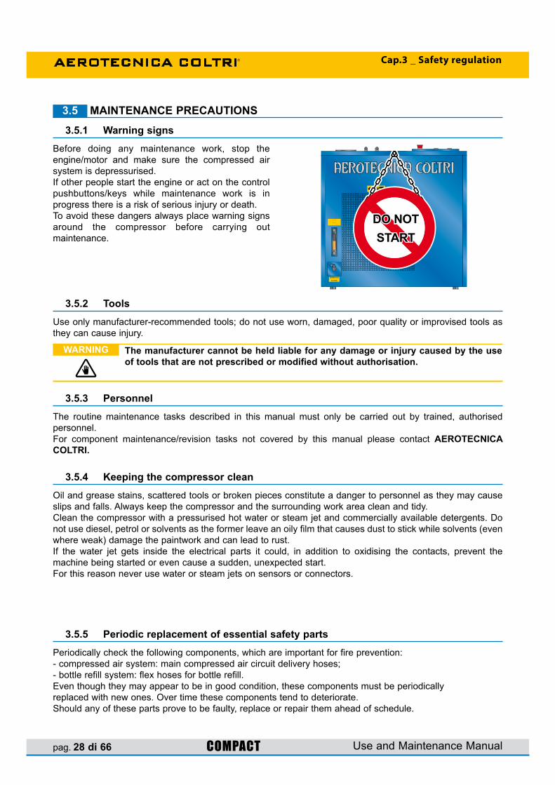
Before doing any maintenance work, stop theengine/motor and make sure the compressed air system is depressurised.If other people start the engine or act on the control pushbuttons/keys while maintenance work is inprogress there is a risk of serious injury or death.To avoid these dangers always place warning signs around the compressor before carrying out maintenance.
DO NOT START
Use only manufacturer-recommended tools; do not use worn, damaged, poor quality or improvised tools as they can cause injury.
The routine maintenance tasks described in this manual must only be carried out by trained, authorisedpersonnel.For component maintenance/revision tasks not covered by this manual please contact AEROTECNICA COLTRI.
Oil and grease stains, scattered tools or broken pieces constitute a danger to personnel as they may cause slips and falls. Always keep the compressor and the surrounding work area clean and tidy.Clean the compressor with a pressurised hot water or steam jet and commercially available detergents. Do not use diesel, petrol or solvents as the former leave an oily film that causes dust to stick while solvents (even where weak) damage the paintwork and can lead to rust.If the water jet gets inside the electrical parts it could, in addition to oxidising the contacts, prevent themachine being started or even cause a sudden, unexpected start.For this reason never use water or steam jets on sensors or connectors.
Periodically check the following components, which are important for fire prevention:- compressed air system: main compressed air circuit delivery hoses;- bottle refill system: flex hoses for bottle refill.Even though they may appear to be in good condition, these components must be periodicallyreplaced with new ones. Over time these components tend to deteriorate.Should any of these parts prove to be faulty, replace or repair them ahead of schedule.

pag. 29 di 66COMPACTUse and Maintenance Manual
Cap.4 _ Technical data
4 - TECHNICAL DATA4.1 TECHNICAL CHARACTERISTICS4.1.1 Crankcase, crankshaft, cylinders, pistons
The crankcase is made of aluminium alloy; the flanges with roller bearings on the filter sides and ball bearings on the fan side that support the crankshaft are kept oil-tight with the crankcase by O-rings between flange and crankcase and the oil retainer between flange and motor shaft.The crankshaft and the connecting rods run on bearings with roller cages only. The connecting rods arefitted on the crankshaft with a single crank angle.The cylinders are made of cast iron, the pistons are made of aluminium and feature traditional multiple piston rings. The high pressure stage piston has a special anti-wear lining. The relative cylinder is self-lubricating.
4.1.2 ValvesThe heads set features outlet and intake valves. The 1st stage head is reed valve type and includes bothintake and pressure. The intake and pressure valves are inserted directly in the respective threaded seats of the 2 nd and 3 rd stage heads. (Pressure valve of 3rd stage have no threads).
4.1.4 Pressure maintenance valveThis valve is fitted after the final filter. When the compressor is switched on it keeps internal systempressure at 100 ±20 bar so as to remove as much water as possible from the air.
4.1.5 LubricationSplash lubrication occurs by oil thrower pins screwed onto the 2 nd and 3 rd stage connecting rods. Third stage lubrication is of the oil vapour type.
4.1.6 Cooling tubesThe cooling pipes are made of stainless steel.
4.1.7 Frame, guardsThe compressor and motor are mounted on a welded steel frame that has been painted with epoxy resins. The frame consists of painted panelling with a handle for the purpose of moving it. Stainless steel frameavailable on request.
It is strictly forbidden to carry out any adjustments to the valve to raise its factorypreset pressure.
Tampering with the safety valve can cause serious damage and renders the warranty null and void.
WARNING
4.1.3 Safety valvesThe safety valves are pre-adjusted during assembly of the compressor and prevent it being damaged in the event of a malfunction. The max pressure, as a function of the valve, as follows:
1st stage safety valve 8 bar - (114 PSI) 2nd stage safety valve 50 bar - (710 PSI) 3rd stage safety or final valve 225 bar - (3200 PSI) 300 bar - (4300 PSI) 330 bar - (4700 PSI)

pag. 30 di 66 COMPACT
FILTRO CON CARTUCCIA DA
SOSTITUIRE AD INTERVALLI
REGOLARI - VEDI MANUALE
FILTER WITH CARTRIDGE
TO BE REPLACED AT REGULAR
INTERVALS – SEE MANUAL
SCARICO OLIO
OIL DRAIN
SCARICO CONDENSA
CONDENSATE DISCHARGE
PRESSOSTATO
PRESSURE
SWITCH
230 Volt
MCH 16/ET COMPACT
19
4
24
16
11
30
9
5
29
28
23
19
13
12
10
8
7 6 29
2
29
29
26
25 25
22
21
15
14
2
1
8
27
24
20
18
17
3
Use and Maintenance Manual
Cap.4 _ Technical data
4.2 MACHINE PARTS1 Frame2 Control pannel3 Condensate discharge pushbutton4 ON pushbutton5 Stop pushbutton6 Emergency pushbutton7 Hour counter8 Motor9 Compressor10 3rd stage pressure gauge11 Automatic shutdown pressure switch12 Air filter13 Final condensate separator14 Active carbon air filter / molecular sieve15 1st stage16 2nd stage17 3rd stage18 Monobloc19 Oil filler plug20 Safety valve21 Maintenance valve22 Cooling fan23 Belt24 Anti-vibration device25 Condensate discharge valves26 Condensate collection can27 Oil drain plug28 Oil level29 Refill hoses connection30 Intake extension hole
pag. 31 di 66COMPACT
SCARICO OLIO
OIL DRAIN
890mm - 35”
84
0m
m -
33
”
60
0m
m -
23
”
PRESSOSTATO
PRESSURE
SWITCH
MANOMETRO
3° STADIO
PRESSURE GAUGE
3° STAGE
230 Volt
TESTPURGE
ONOFF
Use and Maintenance Manual
Cap.4 _ Technical data
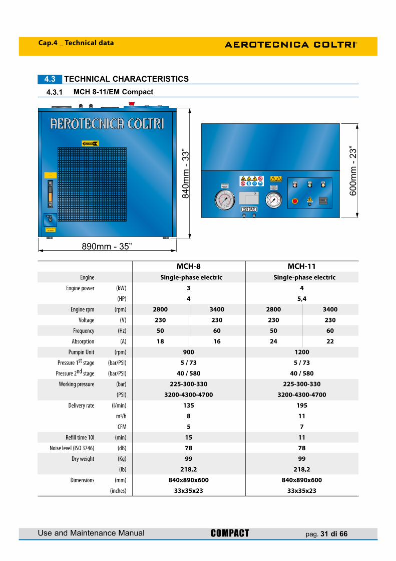
4.3 TECHNICAL CHARACTERISTICS4.3.1 MCH 8-11/EM Compact
MCH-8 MCH-11 Engine Single-phase electric Single-phase electric
Engine power (kW) 3 4
(HP) 4 5,4
Engine rpm (rpm) 2800 3400 2800 3400
Voltage (V) 230 230 230 230
Frequency (Hz) 50 60 50 60
Absorption (A) 18 16 24 22
Pumpin Unit (rpm) 900 1200
Pressure 1st stage (bar/PSI) 5 / 73 5 / 73
Pressure 2nd stage (bar/PSI) 40 / 580 40 / 580
Working pressure (bar) 225-300-330 225-300-330
(PSI) 3200-4300-4700 3200-4300-4700
Delivery rate (l/min) 135 195
m3/h 8 11
CFM 5 7
Refill time 10l (min) 15 11
Noise level (ISO 3746) (dB) 78 78
Dry weight (Kg) 99 99
(lb) 218,2 218,2
Dimensions (mm) 840x890x600 840x890x600
(inches) 33x35x23 33x35x23

pag. 32 di 66 COMPACT
SCARICO OLIO
OIL DRAIN
890mm - 35”
84
0m
m -
33
”
60
0m
m -
23
”
PRESSOSTATO
PRESSURE
SWITCH
MANOMETRO
3° STADIO
PRESSURE GAUGE
3° STAGE
230 Volt
TESTPURGE
ONOFF
Use and Maintenance Manual
Cap.4 _ Technical data
4.3.2 MCH 13-16/ET Compact
MCH-13 MCH-16 Engine Three-phase electric Three-phase electric
Engine power (kW) 4 4,8 5,5 6,6
(HP) 5,5 6,5 7,5 8,9
Engine rpm (rpm) 2840 3410 2850 3420
Voltage (V) 230-400 230-400 440-480 230-400 230-400 440-480
Frequency (Hz) 50 60 60 50 60 60
Absorption (A) 15/8,7 15/8,7 8,7 20/11,6 20/11,6 11,6
Pumpin Unit (rpm) 1350 1550
Pressure 1st stage (bar/PSI) 5 / 73 5 / 73
Pressure 2nd stage (bar/PSI) 40 / 580 40 / 580
Working pressure (bar) 225-300-330 225-300-330
(PSI) 3200-4300-4700 3200-4300-4700
Delivery rate (l/min) 215 265
m3/h 13 16
CFM 7,5 9
Refill time 10l (min) 9 8
Noise level (ISO 3746) (dB) 79,4 81
Dry weight (Kg) 141 151
(lb) 311 333
Dimensions (mm) 840x890x600 840x890x600
(inches) 33x35x23 33x35x23

pag. 33 di 66COMPACT
890mm - 35” 950mm - 37”80mm - 3”
1320m
m -
52”
MCH 32/ET COMPACT
SCARICO OLIO
OIL DRAIN
SCARICO OLIO
OIL DRAIN
PRESSOSTATO
PRESSURE
SWITCH
230 Volt230 Volt
PRESSOSTATO
PRESSURE
SWITCH
Use and Maintenance Manual
Cap.4 _ Technical data
4.3.3 MCH 26-32/ET Compact
MCH-26 MCH-32 Engine Three-phase electric Three-phase electric
Engine power (kW) 2 x 4 2 x 4,8 2 x 5,5 2 x 6,6
(HP) 2 x 5,5 2 x 6,5 2 x 7,5 2 x 8,9
Engine rpm (rpm) 2 x 2840 2 x 3410 2 x 2850 2 x 3420
Voltage (V) 230-400 230-400 440-480 230-400 230-400 440-480
Frequency (Hz) 50 60 60 50 60 60
Absorption (A) 2 x 15/8,7 2 x 15/8,7 2 x 8,7 2 x 20/11,6 2 x 20/11,6 2 x 11,6
Pumpin Unit (rpm) 1350 1550
Pressure 1st stage (bar/PSI) 5 / 73 5 / 73
Pressure 2nd stage (bar/PSI) 40 / 580 40 / 580
Working pressure (bar) 225-300-330 225-300-330
(PSI) 3200-4300-4700 3200-4300-4700
Delivery rate (l/min) 430 530
m3/h 26 32
CFM 15 18
Refill time 10l (min) 5 4
Noise level (ISO 3746) (dB) 72,4 75
Dry weight (Kg) 286 306
(lb) 630 674
Dimensions (mm) 1320x890x860 1320x890x860
(inches) 52x35x33 52x35x33

pag. 34 di 66 COMPACT
890mm - 35”
84
0m
m -
33
”
60
0m
m -
23
”
PRESSOSTATO
PRESSURE
SWITCH
MANOMETRO
1° STADIO
PRESSURE GAUGE
1° STAGE
MANOMETRO
2° STADIO
PRESSURE GAUGE
2° STAGE
MANOMETRO
3° STADIO
PRESSURE GAUGE
3° STAGE
230 Volt
TESTPURGE
ON OFFLOW
LEVELOIL
WRONGROTATION
SCARICO OLIO
OIL DRAIN
Use and Maintenance Manual
Cap.4 _ Technical data
4.3.4 MCH 13-16-18/ET Compact Evo
MCH-13 MCH-16 MCH-18 Engine Three-phase electric Three-phase electric Three-phase electric
Engine power (kW) 4 4,8 5,5 6,6 7,5 7,5
(Hp) 5,5 6,5 7,5 8,9 10 10
Engine rpm (rpm) 2840 3410 2850 3420 2850 3420
Voltage (V) 230-400 230-400 440-480 230-400 230-400 440-480 230-400 230-400 440-480
Frequency (Hz) 50 60 60 50 60 60 50 60 60
Absorption (A) 15/8,7 15/8,7 8,7 20/11,6 20/11,6 11,6 20/11,6 20/11,6 11,6
Pumpin Unit (rpm) 1350 1550 1800
Pressure 1st stage (bar/PSI) 5 / 73 5 / 73 5 / 73
Pressure 2nd stage (bar/PSI) 40 / 580 40 / 580 40 / 580
Working pressure (bar) 225-300-330 225-300-330 225-300-330
(PSI) 3200-4300-4700 3200-4300-4700 3200-4300-4700
Delivery rate (l/min) 215 265 300
m3/h 13 16 18
CFM 7,5 9 10,5
Refill time 10l (min) 9 8 7
Noise level (ISO 3746) (dB) 66,2 68,8 69,8
Dry weight (Kg) 212 222 230
(lb) 468 490 507
Dimensions (mm) 840x890x600 840x890x600 840x890x600
(inches) 33x35x23 33x35x23 33x35x23
pag. 35 di 66COMPACT
PRESSOSTATO
PRESSURE
SWITCH
MANOMETRO
3° STADIO
PRESSURE GAUGE
3° STAGE
230 Volt
SCARICO OLIO
OIL DRAIN
890mm - 35”
85
0m
m -
33
”
60
0m
m -
23
”
Use and Maintenance Manual
Cap.4 _ Technical data
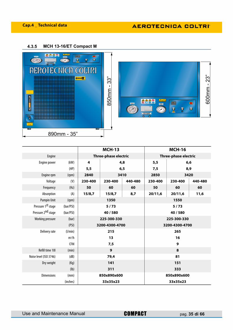
4.3.5 MCH 13-16/ET Compact M
MCH-13 MCH-16 Engine Three-phase electric Three-phase electric
Engine power (kW) 4 4,8 5,5 6,6
(HP) 5,5 6,5 7,5 8,9
Engine rpm (rpm) 2840 3410 2850 3420
Voltage (V) 230-400 230-400 440-480 230-400 230-400 440-480
Frequency (Hz) 50 60 60 50 60 60
Absorption (A) 15/8,7 15/8,7 8,7 20/11,6 20/11,6 11,6
Pumpin Unit (rpm) 1350 1550
Pressure 1st stage (bar/PSI) 5 / 73 5 / 73
Pressure 2nd stage (bar/PSI) 40 / 580 40 / 580
Working pressure (bar) 225-300-330 225-300-330
(PSI) 3200-4300-4700 3200-4300-4700
Delivery rate (l/min) 215 265
m3/h 13 16
CFM 7,5 9
Refill time 10l (min) 9 8
Noise level (ISO 3746) (dB) 79,4 81
Dry weight (Kg) 141 151
(lb) 311 333
Dimensions (mm) 850x890x600 850x890x600
(inches) 33x35x23 33x35x23
pag. 36 di 66 COMPACT
SCARICO OLIO
OIL DRAIN
1042mm - 41,5”
81
2m
m -
32
”230 Volt
71
2m
m -
28
”
Use and Maintenance Manual
Cap.4 _ Technical data
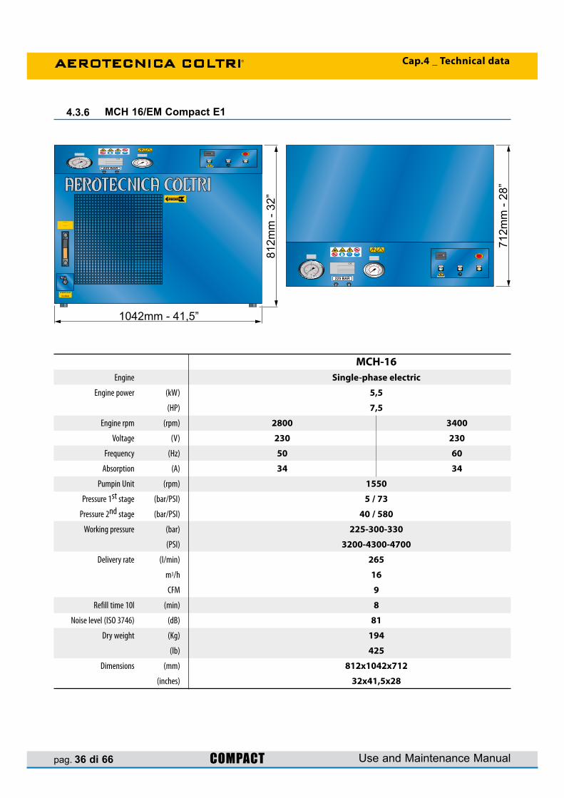
4.3.6 MCH 16/EM Compact E1
MCH-16 Engine Single-phase electric
Engine power (kW) 5,5
(HP) 7,5
Engine rpm (rpm) 2800 3400
Voltage (V) 230 230
Frequency (Hz) 50 60
Absorption (A) 34 34
Pumpin Unit (rpm) 1550
Pressure 1st stage (bar/PSI) 5 / 73
Pressure 2nd stage (bar/PSI) 40 / 580
Working pressure (bar) 225-300-330
(PSI) 3200-4300-4700
Delivery rate (l/min) 265
m3/h 16
CFM 9
Refill time 10l (min) 8
Noise level (ISO 3746) (dB) 81
Dry weight (Kg) 194
(lb) 425
Dimensions (mm) 812x1042x712
(inches) 32x41,5x28

pag. 37 di 66COMPACT
2° STADIO
2 nd STAGE3° STA
DIO3r
d STAG
E
1° STADIO1st STAGE
4
814
11
9
9
1
2 3
5
6
10
16
17
18
19
20
20
15
12
13 7
Use and Maintenance Manual
Cap.4 _ Technical data
PRESSURE CIRCUIT4.4
1 Intake filter 2 Intake valve 1st stage 3 Outlet valve 1st stage 4 Cooling pipe 1st-2nd stage 5 Intake valve 2nd stage 6 Outlet valve 2nd stage 7 Safety valve 1st stage 8 Cooling pipe 2nd-3rd stage 9 Condensate separator 10 Safety valve 2nd stage
11 Pipe separator/3rd stage 12 Intake valve 3rd stage 13 Outlet valve 3rd stage 14 Final cooling pipe 15 Safety valve 16 Pressure gauge 17 Pipe separator/filter 18 Active carbon air filter/molecular sieve 19 Pressure maintenance valve 20 Flex hoses

pag. 38 di 66 COMPACT
1 m
min.1.5 m
1 m
Use and Maintenance Manual
Cap.5 _ Handling and installation
Before proceeding with the installation tasks described below, read Chapter 3 “SAFETY REGULATIONS” carefully.
WARNING
Proceeding with the utmost care when lifting, transferring and positioning thecomp ressor.
IMPORTANT
5 - HANDLING AND INSTALLATION5.1 UNPACKING
5.2 HANDLING
5.3 INSTALLATION
5.3.1 Positioning- Position the compressor in the designa ted area
and check it is level. For compressor dimensions please consult section 4.3 “Technical characteristics”.
- Check that the area in which the compressor is to be positioned is adequately ventilated: good air exchange (more than one window), no dust and no risk of explosion, corrosion or fire.
- If ambient temperatures exceed 45°C air conditioning will be necessary.
- Position the compressor no closer than 1 m to surrounding walls; the gap between compressor and ceiling should be at least 1.5 m. These distances ensure proper compressor operation and proper cooling of the pumping unit.
- Make sure that lighting in the area is sufficient to identify every detail (such as the writing on the info labels); use artificial lighting where daylight is on its own insufficient.
Compact series compressors are sent fully assembled, with the flex hoses separate.The compressor is packed in a cardboard box on a pallet to simplify handling and transport.The box containing the compressor must be moved according to the instructions shown on the box itself.The machine is supplied with the following asstandard:- two 1200 mm refill hoses with filling valves- use and maintenance manual- use and maintenance manual appendix (safety regulations)- lubricating oil (2 litres)- active carbon and molecular sieve filte cartrige.
After separating the compressor from its packaging it can be transported to the designated placement area.Transfer will require the use of a fork-lift or transpallet (of suitable load-bearing capacity): the forks must be positioned in the support feet on which the europallet is positioned.

pag. 39 di 66COMPACT
a
b
Use and Maintenance Manual
Cap.5 _ Handling and installation
5.3.2 Air intake extension connection
Use only a flexible pipe with internal steel braiding reinforcement so as to prevent kinks and a consequent reduction of cross-section.Do not aspirate harmful gases or exhaust fumes.
WARNING
If the compressor is installed in an area without the necessary ventilation requisites described in section 5.3.1 “Positioning”, it will be necessary to install an air intake extension leading in from outdoors or a place with the cited ventilation requisites.- The extension, supplied as an optional, must be
connected to the intake connector (a).- Connect extension pipe to fitting.- Pass the pipe through the hole on the side panel
(b).- Fit the supplementary intake filter on the extremity
of the extension pipe.- Position the end of the extension with the air intake
filter in a properly ventilated area sheltered from weather and exhaust fumes.
- Point the air intake against the wind.- Check that there are no kinks or breaks along the
pipe. If it is damaged replace it.

pag. 40 di 66 COMPACT Use and Maintenance Manual
Cap.5 _ Handling and installation
Before inserting the plug, check that the electrical system complies with thestandards in force in the country of installation. A proper earth (ground) system is an essential safety requisite.
An efficient compressor ground (earth) system is an essential compressor safety requisite.
The mains power connection plug must be type-approved in compliance with the relevant standards and have an ON-OFF switch (not supplied).
WARNING
Electrical connection5.3.3
The compressor is supplied with an electrical lead and, depending on the model, with a plug (see diagram at right).To connect up to the power supply just insert the plug in the mains power socket.Check that the data on the compressor ID plate is compatible with mains power supply, especially as regards rated current and voltage.The mains power system must have an efficient ground (earth); check that the earth resistance value complies with the protection / operational requirements of the compressor electrical system.
Model: MCH-8/EMSchuko plug supplied
Modello: MCH-11/EM32A 2P+E plug not supplied
Model: MCH-13/ET16A 3P+E plug not supplied
Model: MCH-16/ET - MCH26-32/ET32A 3P+E plug not supplied

pag. 41 di 66COMPACT
a
a
Use and Maintenance Manual
Cap.6 _ Using the compressor
6 - USING THE COMPRESSORPRELIMINARY CHECKS BEFOR USING FOR THE FIRST TIME6.1
Filling with lubricating oil6.1.1
Checking for proper electrical connection6.1.2
The operator must check that the compressor is supplied with:- use and maintenance manual;- the appendix to the use and maintenance manual (where applicable);If the compressor is sold on the customer/user must provide the purchaser with a complete, undamaged use and maintenance manual.
At the time of delivery the compressor does not contain lubricating oil; this is supplied together with thecompressor in cans contained in the packaging.For filling instructions sees section “7.6.3 Changing the lubricating oil”.
Check for proper connection of electrical phases by checking that the cooling fan rotates in the direction indicated on the label (a) on the fan cover.If the direction of rotation is not as indicated by the arrow it will be necessary to disconnect the electrical power supply and invert two of the three phases on the main power lead.
CHECKS TO BE RUN AT THE START OF EACH WORKING DAY6.2Inspect the exterior of the compressor (couplings, pipes, pneumatic components etc.) and check for any oil leaks. Replace parts where necessary or contact AEROTECNICA COLTRI.
Check that the lubricating oil level (a) is within acceptable limits.Note that an excessive quantity of oil can causeinfiltrations in the cylinders and leave deposits on the valves while too low a level prevents proper lubrica-tion and could cause engine seizure.If the oil level is not within the minimum andmaximum limits top up or drain as described insection “7.6.3 Changing the lubricating oil”.
Lubricating oil level check6.2.1
Before carrying out this task disconnect the compressor from the mains power supply.
Do not invert or disconnect the ground (earth) wire (yellow/green).
DANGER

pag. 42 di 66 COMPACT Use and Maintenance Manual
Cap.6 _ Using the compressor
The use and maintenance manual is an integral part of the compressor and must always be handed over in the event of a change of ownership.
WARNING
Checking that the refill flex hoses are in good condition6.2.2
Storing technical documentation6.2.3
Inspect the refill hoses and make sure there are no cuts, holes, abrasions, leaks etc. If necessaryreplace with new hoses.
The use and maintenance manual and its appendices must be stored carefully and must always bekept where they can be accessed easily for immediate consultation.
PRELIMINARY TASKS6.3
Checking the safety valves6.3.1Check that safety valves are working properly: start the compressor with the final taps closed and the pressure switch cursor at the maximum end of the scale so that circuit pressure rises rapidly and the valves trip at the set pressure.The safety valve are pre-adjusted to 225 bar (3200 PSI), 300 (4300 PSI) and 330 bar (4700 PSI).
Check that the bottles to be refilled are in good condition: they must have been tested by the relevantauthorities (stamped and/or certified). Run a visual check on the exterior.
Check that the refill hose and relevant fitting are in good condition.
After being refilled do not empty the bottles completely, not even during winter storage or long periods ofinactivity: this will stop humidity getting in.
Use only tested bottles (as proven by a test stamp and/or certificate).The working and bottle refill pressures are shown on the bottles themselves.It is forbidden to refill them at a pressure greater than that indicated.
WARNING
Should bottles show evident signs of internal/extern al corrosion, do not refill them even if they have been tested.
DANGER
Tampering with the safety valve to increase the pressure setting is strictly forbidden.Tampering with the safety valve can seriously damage the compressor, cause serious injury to personnel and renders the warranty null and void.
IMPORTANT
Should the safety valve fail to work properly contact the AEROTECNICA COLTRIassistance service.
IMPORTANT

pag. 43 di 66COMPACT
PRESSOSTATO
PRESSURE
SWITCH
MANOMETRO
1° STADIO
PRESSURE GAUGE
1° STAGE
MANOMETRO
2° STADIO
PRESSURE GAUGE
2° STAGE
MANOMETRO
3° STADIO
PRESSURE GAUGE
3° STAGE
AEROTECNICA COLTRI S.r.l.Via Colli Storici 177
25010 DESENZANO D/G (BS) ITALY
Tel. 030/9910301-9910297
Fax. 030/9910283
MODEL
YEAR
S/N.
TYPE
MCH 13-16
2008
MOTOR THREE-PHASE
POWER 4 Kw
0000
COMPACT
230 Volt
TESTPURGE
ON OFFLOW
LEVELOIL
WRONGROTATION
PRESSOSTATO
PRESSURE
SWITCH
MANOMETRO
3° STADIO
PRESSURE GAUGE
3° STAGE
AEROTECNICA COLTRI S.r.l.Via Colli Storici 177
25010 DESENZANO D/G (BS) ITALY
Tel. 030/9910301-9910297
Fax. 030/9910283
MODEL
YEAR
S/N.
TYPE
MCH 13-16
2008
MOTOR THREE-PHASE
POWER 4 Kw
0000
COMPACT
230 Volt
TESTPURGE
ONOFF
MCH 16/ET COMPACT
1
1
4
4
3 2
10
10
1112
12
7
7
8
8
9
9
5 6
a1
b
Use and Maintenance Manual
Cap.6 _ Using the compressor
COMPACT EVO control pannel
COMPACT control pannel
It is forbidden to alter pressure parameters without authorisation from AEROTECNICA COLTRI. Any unauthorised modifications shall render the warranty null and void.
WARNINGCONTROL PANEL6.4
1 Automatic shutdown pressure switch The automatic shutdown pressure switch (1)
determines the compressor shutdown pressure. The shutdown pressure can be set via the
regulator compressor reaches the set pressure it shuts down automatically.
The compressor can reach a maximum pressure of 225-300-330 bar (3200-4300-4700 PSI).
2 1st stage pressure gauge Indicates the pressure inside the 1st compression
stage.3 2nd stage pressure gauge Indicates the pressure inside the 2nd compression
stage.4 3rd stage pressure gauge Indicates 3rd compression stage pressure and
final refill pressure.5 Direction of rotation warning light If the light (5) comes on this means that the direction of compressor rotation is incorrect. To restore correct
rotation see section “6.1.2 Checking electrical phase connections”.6 Oil level warning light If the light (6) comes on this means that the oil level is too low; to restore the oil level see section “7.6.3
Changing lubricating oil”.

pag. 44 di 66 COMPACT
PRESSOSTATO
PRESSURE
SWITCH
MANOMETRO
1° STADIO
PRESSURE GAUGE
1° STAGE
MANOMETRO
2° STADIO
PRESSURE GAUGE
2° STAGE
MANOMETRO
3° STADIO
PRESSURE GAUGE
3° STAGE
AEROTECNICA COLTRI S.r.l.Via Colli Storici 177
25010 DESENZANO D/G (BS) ITALY
Tel. 030/9910301-9910297
Fax. 030/9910283
MODEL
YEAR
S/N.
TYPE
MCH 13-16
2008
MOTOR THREE-PHASE
POWER 4 Kw
0000
COMPACT
230 Volt
TESTPURGE
ON OFFLOW
LEVELOIL
WRONGROTATION
PRESSOSTATO
PRESSURE
SWITCH
MANOMETRO
3° STADIO
PRESSURE GAUGE
3° STAGE
AEROTECNICA COLTRI S.r.l.Via Colli Storici 177
25010 DESENZANO D/G (BS) ITALY
Tel. 030/9910301-9910297
Fax. 030/9910283
MODEL
YEAR
S/N.
TYPE
MCH 13-16
2008
MOTOR THREE-PHASE
POWER 4 Kw
0000
COMPACT
230 Volt
TESTPURGE
ONOFF
MCH 16/ET COMPACT
1
1
4
4
3 2
10
10
1112
12
7
7
8
8
9
9
5 6
Use and Maintenance Manual
Cap.6 _ Using the compressor
7 Manual condensate discharge button Pressing the yellow manual condensate discharge button (7) drains the condensate collected in the
special recipient during use of the compressor (no further tasks required: drainage interval managed with the pressure switch timer). To drain the condensate see section “7.9 Condensate discharge”.
8 ON pushbutton To start the compressor press the green ON pushbutton (8). The compressor will then run until the
pressure that has been set on the adjustable pressure switch (1) is reached or until the safety valve release over pressure.
9 OFF pushbutton Press the red OFF pushbutton (9) to stop the compressor.10 Pulsante emergenza In an emergency situation stop the compressor by pressing the red emergency pushbutton (10). Check
that the emergency shutdown pushbutton is working properly at the start of each working day by switching on the compressor and pressing it. If the compressor fails to shut down immediately after pressing the emergency pushbutton disconnect the compressor from the power supply and contact AEROTECNICA
COLTRI.11 Thermostat The thermostat (11) indicates the temperature inside the compressor. If the temperature is higher or lower
than the parameters set on the thermostat the compressor shuts down and can only be restarted once temperature has returned within the permitted range.
12 Hour counter The hour counter (12) indicates the number of working hours of the compressor: this provides a time
reference for scheduled maintenance.
COMPACT EVO control pannel
COMPACT control pannel

pag. 45 di 66COMPACT
PRESSOSTATO
PRESSURE
SWITCH
MANOMETRO
3° STADIO
PRESSURE GAUGE
3° STAGE
AEROTECNICA COLTRI S.r.l.Via Colli Storici 177
25010 DESENZANO D/G (BS) ITALY
Tel. 030/9910301-9910297
Fax. 030/9910283
MODEL
YEAR
S/N.
TYPE
MCH 13-16
2008
MOTOR THREE-PHASE
POWER 4 Kw
0000
COMPACT
230 Volt
TESTPURGE
ONOFF
MCH 16/ET COMPACT
c b
a
d
a
e
Use and Maintenance Manual
Cap.6 _ Using the compressor
STARTING AND SHUTTING DOWN6.5
Before starting the engine open the condensatedischarge points (a) to prevent a “strained” start (only MCH 8/11 model).- check the voltage and that there is a proper earth
ontact.- press the start pushbutton (b);- for models with three-phase electric motor check th
at the direction of rotation of the electric motor is as indicated by the arrow (e) on the cover (if it is not refer to “6.1.2 Checking for proper electrical connection”);
- close the condensate discharge points. (a) (only MCH 8/11 model);
- to switch off the compressor press the pushbutton (c).
If emergency or danger situations occur press the emergency pushbutton (d).To restore normal compressor operation rotate the emergency pushbutton clockwise (d).
WARNING
These tasks must be carried out by qualified personnel who have been trained to use the compressor.
IMPORTANT

pag. 46 di 66 COMPACT Use and Maintenance Manual
Cap.6 _ Using the compressor
During bottle refill those not involved in the refill procedure must maintain a safety distance of at least 3 metres. Also, it is forbidden to disconnect the hoses from the fittings or the fill valve while the machine is under pressure.
WARNING
During refill the operator must be in the work area.It is advisable, during the bottle refill phase, to submerge the bottles in cold water so as to reduce the pressure drop.
IMPORTANT
TANK REFILL6.6
The available bottle refill connectors are:
BC DIN 230Cod.: SC000470
optional DIN/INT REDUCERCod.: RE100350
BC DIN 300 USACod.: SC000460/SP
BC DIN 300Cod.: SC000460
BC INTCod.: SC000450
BC ITALIAN CONNECTOR FOR FIRE MAN SCBA
Cod.: SC000475

pag. 47 di 66COMPACT
A C
A C
A C
A C
AC CA
AC
c
d
e
f
a
b
c d
a
f
Use and Maintenance Manual
Cap.6 _ Using the compressor
Use only tested bottles (as proven by a test stamp and/or certificate).The working and bottle refill pressures are shown on the bottles themselves.It is forbidden to refill them at a pressure greater than that indicated.
WARNING
IMPORTANT If an emergency situation arises during refill shut down the compressor immediately (see “6.5 Starting and shutting down”).The compressor is nevertheless equipped with a safety system that shuts it down
automatically when:- The pressure setting on the pressure switch has been reached.- The electrical power supply is temporarily cut.- The electric motor overload device is tripped.Following an emergency shutdown always make sure the cause of the emergency has been eliminated before proceeding with another refill.
To refill bottles proceed as follows:- Fit the hose connector (a) to the bottle valve (b).- Screw in the fixing knob (c) until it is completely tightened.- Check that the bleed valve (f) is closed by rotating it clockwise.- Open the valve (d) by rotating it anticlockwise.- Start the compressor.- Open the valve (e) by rotating it anticlockwise.- Start the compressor.- When the refill has been completed shut the compressor down.- Close valves (d) and (e) by rotating them clockwise.- Open the bleed valve (f) by rotating it anticlockwise until all the residual air in the fitting has been expelled.- Unscrew the fixing knob (c) by rotating it anticlockwise- Disconnect the bottle coupling.

pag. 48 di 66 COMPACT Use and Maintenance Manual
Cap.7 _ Maintenance
Maintenance tasks must only be carried out by the AEROTECNICA COLTRI Customer Assistance Service or qualified personnel.
WARNING
All maintenance tasks must be carried out with the compressor off and the power lead unplugged from the mains socket.
DANGER
7 - MAINTENANCE
FOREWORD7.1
GENERAL7.2
UNSCHEDULED WORK7.3
To obtain the best possible performance from the compressor and ensure a long working life for all its parts it is essential that personnel follow the use and maintenance instructions with extreme diligence.It is thus advisable to read the information below and consult the manual every time an inconvenience arises.For further information please contact our assistance centre:
Contact the AEROTECNICA COLTRI SpA. Maintenance Service CentreTel. +39 030 99 10 297Fax. +39 030 99 10 283
e-mail: [email protected]
- Proper preservation of the compressor requires thorough cleaning.- This type of refill station, designed and built according to the most advanced technological criteria, requires only minimum preventive and routine maintenance.- Before carrying out any maintenance tasks, run checks and/or controls on the compressor, switch off the compressor, remove the plug from the mains socket.- The residual pressure present in the compressor (pumping circuit) must be released.- During disassembly and re-assembly of the compressor, always use suitable wrenches/tools so as not to damage the relevant components.- Loosen stiff parts with a copper or plastic mallet.- When refitting parts make sure they are clean and lubricated sufficiently.- Compressor maintenance tasks must only be carried out by authorised personnel and recorded in the chapter “11 Maintenance register”of this manual.
Involves repair and/or replacement of the mechanical parts of one or more compressor components:this work normally needs doing only after some years of use. If substantial modifications are made, themanufacturer cannot be held liable for any dangers that might arise.
This work must be carried out by the assistance centre.

pag. 49 di 66COMPACTUse and Maintenance Manual
Cap.7 _ Maintenance
SCHEDULED MAINTENANCE TABLE7.4
TROUBLESHOOTING7.5
Checking and cleaning Change
5 10 30 40 50 250 500 1000 2000 3000 4000 Maintenance hours hours hours hours hours hours hours hours hours hours hours Condensate discharge
Automatic shutdown check
Lubricating oil level check
Main functions check
Clean condensate discharge valves
Condensate discharge O-rings
Condensate discharge valves
Belt wear and tension
Cleaning the separator filter element
Oil change
1st , 2nd stage valves
3rd stage valves
HP water/oil separator
HP filter body
1st , 2nd stage segments
3rd stage segments
Check and replace HP flex hoses
Fitting/hose leak
General check-up
Pumping unit, general overhaul
1st and 2nd stage safety valves
Safety valve
Problem Cause Solution The electric motor does not start Phase missing Check fuses or condenser
Rotation speed and flow rate Motor power too low Check the motor and the line decrease The belt slips Restore proper belt tension The flow rate diminishes Valves not working Contact technical assistance without rpm decreasing 4 th stage piston worn Contact technical assistance Fittings loose / leaking seals Check for leaks with soapy water and eliminate them Intake filter clogged Replace filter Intake extension kinked Straighten, use stiffer pipe Piston or piston rings worn Contact technical assistance Air smells of oil Filter cartridge exhausted Replace Piston rings worn Contact technical assistance Compressor overheats Direction of rotation wrong Correct direction of rotation Cooling tubes dirty Contact technical assistance Incomplete valve closure Contact technical assistance (causing overload of another stage)

pag. 50 di 66 COMPACT
a
Use and Maintenance Manual
Cap.7 _ Maintenance
Do not carry out these tasks if the compressor has only just shut down; wait for the compressor to cool.Any oil spilt during the oil/filter change could cause personnel to slip; wear protective garments and anti-slip footwear and remove any traces of oil immediately.Both oil and filter are classified as special wastes and must therefore be disposed of in compliance with the anti-pollution laws in force.All maintenance work must be carried out with the compressor OFF and the power supply lead unplugged from the mains socket.
DANGER
The compressor must be placed on a solid surface with a tilt of no more than 5°.IMPORTANT
CHECKING AND CHANGING THE LUBRICATING OIL7.6After putting the compressor into service the lubricating oil must be changed after the first 50 working hours.The lubricating oil must be changed every 250 hours working hours or annually.
Checking the oil level7.6.2
Oil table7.6.1
Sump capacity litres / Quart 1,8 Recommended oils COLTRI OIL CE750 CHEMLUBE 751 ANDEROL 755
Check that the level of lubricating oil (a) is within the allowed limits.Note that an excessive quantity of oil can cause infiltrations in the cylinders and leave deposits on the valves while too low a level prevents proper lubrication and could cause engine seizure.If the oil level is not within the minimum and maximum limits top up or drain as described in section “7.6.3 Changing the lubricating oil”.

pag. 51 di 66COMPACT
c
a
b
d
Use and Maintenance Manual
Cap.7 _ Maintenance
Changing the lubricating oil7.6.3The lubricating oil must be changed every 250working hours or annually. To change the oil proceed as described:- position a recipient under the drain plug (a) so that the oil flows into the exhausted oil recipient (recipient capacity of at least 2 litres required).- loosen the top-up plug (b)- remove the plug (d), open the tap (a) and drain all
the oil;- close the drain plug (a)- open the top plug (b)- fill the oil sump with 1.8 litres of oil from top oil plug (see “7.6.1 Oil table”)- close the oil top plug (b).- switch on the compressor and run it depressure area for 30 seconds- switch off the compressor and remove the plug from the power socket- check the oil level (c); if the oil level is not within the
allowed limits top up or drain.- replace the cap (d).

pag. 52 di 66 COMPACT
a
b
Use and Maintenance Manual
Cap.7 _ Maintenance
Do not carry out these tasks if the compressor has only ju st shut down; wait for thecompressor to cool.All maintenance work must be carried out with the compressor OFF and the power supply lead unplugged from the mains socket.
DANGER
Should the safety valve fail to operate properly contact the AEROTECNICA COLTRI technical assistance service.
IMPORTANT
If the compressor is used in a dusty environment the filter change interval should be reduced to every 100 hours.
IMPORTANT
After putting the compressor into service the intake filter must be changed after the first 50 working hours.The air filter must then be changed every 250 working hours or annually.Rotate the filtration cartridge in the filter by 90° every 50 hours.
CHANGING THE INTAKE FILTER7.7
The air intake filter must be changed every 250working hours or annually.To change the filter proceed as follows:- turn the air filter cover (a) by rotating it anticlockwise;- remove the air filter cartridge (b);- replace the cartridge with a new one;- re-close the cover (a): screw it back on clockwise.
CHECKING THE SAFETY VALVE7.8The final safety valve protects bottles from being filled with air at too high a pressure; the valve setting is made at the time of testing the compressor.The safety valve must be tested every time bottles are refilled.After attaching the coupling to the bottle start the compressor with the bottle valves closed.Once you have checked, using the gauge, that the safety valve trips properly at maximum working pressure,open the valves and start the refill.

pag. 53 di 66COMPACT
PRESSOSTATO
PRESSURE
SWITCH
MANOMETRO
3° STADIO
PRESSURE GAUGE
3° STAGE
AEROTECNICA COLTRI S.r.l.Via Colli Storici 177
25010 DESENZANO D/G (BS) ITALY
Tel. 030/9910301-9910297
Fax. 030/9910283
MODEL
YEAR
S/N.
TYPE
MCH 13-16
2008
MOTOR THREE-PHASE
POWER 4 Kw
0000
COMPACT
230 Volt
TESTPURGE
ONOFF
MCH 16/ET COMPACT
aa
b
f
d
de
c
e
Use and Maintenance Manual
Cap.7 _ Maintenance
Do not carry out these tasks if the compressor has only ju st shut down; wait for thecompressor to cool.All maintenance work must be carried out with the compressor OFF and the power supply lead unplugged from the mains socket.
DANGER
The condensate can must be emptied at the end of every working day.IMPORTANT
CONDENSATE DISCHARGE7.9
Condensation accumulates in the condensate separator; the condensate must be discharged every 10-15 minutes of compressor use.
Condensate discharge occurs automatically every 7 minutes. The yellow TEST PURGE pushbutton (b) must be pressed every day to make sure that the discharge valve is working properly.The condensate is collected in a can (c); periodically check this can to prevent overfill and consequent leakage of the condensate liquid. To empty the can remove it from the outside via the aperture on the side frame, remove the condensate drain hoses (d) from the fittings (e), empty the can and collect the condensate in a container; re-insert the hoses (d) and put the can back in its housing.
If the condensate needs to be drained manually, use the drain taps (a) and collect the condensate in a suitable container. Re-close the taps.
Every 250 hours it is necessary to replace theSINTERED FILTER inside the solenoid valve fitting(f).
Condensate must be disposed of according to the instructions shown in section “9.1 Waste disposal”.

pag. 54 di 66 COMPACT
d
d
a
c
a
b
Use and Maintenance Manual
Cap.7 _ Maintenance
Do not carry out these tasks if the compressor has only just shut down; wait for the compressor to cool.All maintenance work must be carried out with the compressor OFF and the power supply lead unplugged from the mains socket.
DANGER
To change a belt proceed as follows:- insert a screwdriver (a) between the belt (b) and the motor pulley (c).- take the belt out of the pulley groove.- replace the belt with a new one, making sure that model and length are correct: check that the characteristics of the new belt are identical to the old one.- insert the belt in the groove of the motor pulley (c).- insert the belt in the groove of the compressor pulley (d): turn the pulley by hand until the belt slips into the pulley groove perfectly (second diagram).- check that the belt is inserted perfectly in the grooves of both pulleys and that belt tension is correct. If the tension of the new belt still fails to comply with the necessary requisites contact AEROTECNICA COLTRI assistance service.
TRANSMISSION BELT7.10Belt tension must be checked monthly.The transmission belts must be replaced every 500 working hours of the compressor.
Checking transmission belt tension7.10.1
To check the tension on the belt (a) exert a pressure of approximately 10 Kg on the belt; check that the belt does not flex by more than 1 cm with respect to its original position.Should it flex more than this replace the belt.
Changing transmission belt7.10.2

pag. 55 di 66COMPACT
d
a
c
b
Use and Maintenance Manual
Cap.7 _ Maintenance
ACTIVE CARBON FILTER / MOLECULAR SIEVE7.11The active carbon filter must be replaced at intervals calculated on the basis of the characteristics of theenvironment in which the compressor is located. To calculate these intervals refer to the table below.
The filter must nevertheless be replaced before the air becomes malodorous.
Filter replacement frequency calculation table7.11.1
Changing the active carbon filter / molecular sieve7.11.2
To change the active carbon filters (a) proceed as follows:- vent all the compressed air inside the circuit.- use the tool (b) to lever the screw heads (d) on the plug (c) and rotate counter clockwise.
Temp. Temp. Correction Filter duration Filter duration Filter duration Filter duration Filter duration (°C) (°F) factor (hours) (hours) (hours) (hours) (hours) MCH-8 MCH-11 MCH-13-26 MCH-16-32 MCH-18 50 122 0,2 (70x0,2)=14 (55x0,2)=11 (50x0,2)=10 (40x0,2)=8 (36x0,2)=7 40 104 0,34 (70x0,34)=24 (55x0,34)=19 (50x0,34)=17 (40x0,34)=14 (36x0,34)=12 30 86 0,57 (70x0,57)=40 (55x0,57)=31 (50x0,57)=28 (40x0,57)=23 (36x0,57)=20 20 68 1 70 55 50 40 36 10 50 1,2 (70x1,2)=78 (55x1,2)=66 (50x1,2)=60 (40x1,2)=48 (36x1,2)=43 5 41 1,4 (70x1,4)=98 (55x1,4)=77 (50x1,4)=70 (40x1,4)=56 (36x1,4)=50 0 32 1,6 (70x1,6)=112 (55x1,6)=88 (50x1,6)=80 (40x1,6)=64 (36x1,6)=57
Do not carry out these tasks if the compressor has only just shut down; wait for the compressor to cool.All maintenance work must be carried out with the compressor OFF and the power supply lead unplugged from the mains socket.Depressurise the entire compressor circuit before carrying out any maintenance tasks.
DANGER
If the compressor is used in an environment where CO (exhaust fumes) may bepresent it is compulsory to use CO-fixing filters; these can be supplied on request.
IMPORTANT
For compressors used in the USA and CANADA the use of LAWRENCE FACTORfiltration cartridges is recommended.
IMPORTANT

pag. 56 di 66 COMPACT
c
c
gg
e
f
e
Use and Maintenance Manual
Cap.7 _ Maintenance
The active carbon filters are classified as special waste: they must be disposed of in compliance with the anti-pollution standards in force.
WARNING
It is essential that there be a filtration cartridge (e) inside the active carbon filters (a) every time the compressor is used.
IMPORTANT
- remove the filter plug (c).- unscrew the cartridge (e) from the plug (c).- replace the cartridge (e) with a new one.- screw the new cartridge onto the plug (c).- close the filter plug (c) and tighten with the wrench (b).
There are O-rings on the filter plug and cartridge (f-g). If these O-rings deteriorate air is vented through the cap (c).If you notice any venting replace the O-rings.When changing the O-rings observe the precautions described at the beginning of the relevant section of the manual.

pag. 57 di 66COMPACT
a a
Use and Maintenance Manual
Cap.7 _ Maintenance
The hoses must be changed periodically (every 3 years or ever 1000 hours) or when they show signs of abrasion/wear/damage.The bending radius of the hoses must not be less than 250 mm.
IMPORTANT
DANGER Do not carry out these tasks if the compressor has only just shut down; wait for the compressor to cool.All maintenance work must be carried out with the compressor OFF and the power supply lead unplugged from the mains socket.Vent the air from the compressor before carrying out any maintenance tasks.
Tank refill pressure is very high; therefore, before refilling the tanks check that the hoses are perfect-ly connected and in good condition. Check also that the valves on any unused hoses are closed properly so as to prevent the dangers that derive from hose whiplash.
When the tanks are being refilled unauthorised personnel must remain at a distance of at least 3 metres.
It is strictly forbidden to disconnect the hoses from the fittings or refill valve when the machine is under pressure.
CHANGING THE FLEX HOSES7.12
To change the bottle refill hoses proceed as follows:- disconnect the bottle refill hoses by unscrewing the fittings (a) (17 mm wrench).- replace the old hoses with new ones.- screw the hoses onto the connectors (a).- use a dynamometric wrench to tighten the hoses on the compressor with a torque of 15 Nm.

pag. 58 di 66 COMPACT Use and Maintenance Manual
Cap.8 _ Storage
8 - STORAGEShould the compressor not be used, it must be stored in a dry sheltered area at an ambient temperature of between 0 °C and 40 °C.Store the compressor away from sources of heat, flames or explosive.
STOPPING THE MACHINE FOR A BRIEF PERIOD8.1
STOPPING THE MACHINE FOR A LONG PERIOD8.2
If you do not intend to use the compressor for a brief period proceed with general cleaning.
If you do not intend to use the compressor for a long period, extract the active carbon filter cartridge.Run the compressor for a few minutes without actually filling bottles so as to flush out all the residualcondensate. Stop the compressor, disassemble the intake filter, restart the compressor and spray a few drops of oil into the air intake hole so that a light film of lubricant is aspirated and penetrates the interior of thecompressor. Stop the compressor and refit the air intake filter. Clean the external parts: eliminate anymoisture, salt or oil deposits. Protect the compressor from dust and water by storing it in a clean, dry place.Switch off the machine via the main switch and remove the plug from the mains power socket.Proceed with a thorough general clean of all machine parts.During machine downtimes it is advisable to run the compressor for 20 minutes every 15 days.

pag. 59 di 66COMPACTUse and Maintenance Manual
Cap.9 _ Dismantling and putting out of service
9 - DISMANTLING AND PUTTING OUT OF SERVICEShould you decide not to use the compressor or any of its parts any longer you must proceed with itsdismantling and putting out of service.These tasks must be carried out in compliance with the standards in force.
WASTE DISPOSAL9.1
DISMANTLING THE COMPRESSOR9.2
Use of the compressor generates waste that is classified as special. Bear in mind that residues fromindustrial, agricultural, crafts, commercial and service activities not classified by quality or quantity as urban waste must be treated as special waste. Deteriorated or obsolete machines are also classified as special waste.Special attention must be paid to active carbon filters as they cannot be included in urban waste:observe the waste disposal laws in force where the compressor is used.Bear in mind that it is compulsory to record loading/unloading of exhausted oils, special wastes andtoxic-harmful wastes that derive from heavy/light industry processes. Exhausted oils, special wastes and toxic-harmful waste must be collected by authorised companies.It is especially important that exhausted oils be disposed of in compliance with the laws in the country of use.
Dismantle the compressor in accordance with all the precautions imposed by the laws in force in the country of use. Before demolishing request an inspection by the relevant authorities and relative report.Disconnect the compressor from the electrical system.Eliminate any interfaces the compressor may have with other machines, making sure that interfaces between remaining machines are unaffected.Empty the tank containing the lubricating oil and store in compliance with the laws in force.Proceed with disassembly of the individual compressor components and group them together according to the materials they are made of: the compressor mainly consists of steel, stainless steel, cast iron, aluminium and plastic parts.Then scrap the machine in compliance with the laws in force in the country of use.
Bear in mid that oil, filters or any other compressor part subject to differentiated waste collection must be disposed of in compliance with the standards in force.
WARNING
Should the compressor, or a part of it, be out of service its parts must be rendered harmless so they do not cause any danger.
WARNING
Disassembly and demolition must only be carried out by qualified personnel.IMPORTANT
At every stage of demolition observe the safety regulations contained in this manual carefully.
IMPORTANT
10 - INSTRUCTIONS FOR EMERGENCY SITUATIONSFIRE10.1
In the event of fire use a CO2 extinguisher in compliance with the relevant standards in force.Contact the fire brigade.

pag. 60 di 66 COMPACT Use and Maintenance Manual
Cap.11 _ Maintenance register
11 - MAINTENANCE REGISTER
Customers continue to receive assistance after the purchase of a compressor.To this end AEROTECNICA COLTRI has created an assistance network covering the entire country.
The scheduled maintenance programme is designed to keep your compressor in perfect working order.Some simple tasks, described in this manual, can be carried out directly by the customer; others, instead, require that the work be carried out by trained personnel. For the latter we recommend you always contact our assistance network.This section provides a simple tool with which to request assistance and register completed scheduledmaintenance work.Start-up and maintenance checks/tasks, once completed by our qualified technician, are registered in this maintenance chapter by way of an official stamp, signature and inspection date; the number of working hours is also registered.The maintenance schedules/coupons easily let you know when our assistance service should be contacted to carry out work.
ASSISTANCE SERVICE11.1
SCHEDULED MAINTENANCE11.2
Where compressors are used in particularly difficult conditions (high levels of pollution, presence of solidparticulate in suspension etc.), scheduled maintenance tasks must be carried out more frequently as per the advice given by our assistance network.
USING THE COMPRESSOR UNDER HEAVY-DUTY CONDITIONS11.3
Our qualified technicians are constantly in contact with the head offices of our company where there is an assistance network coordination and support centre, better known as the Customer Care Centre.To contact us:
Telephone: +39 030 9910301 +39 030 9910297 Fax: +39 030 9910283 E-mail: [email protected]
THE CUSTOMER CARE CENTRE11.4
Our qualified technicians are at your disposal at any time to carry out maintenance work or repairs; we use only original spare parts so as to ensure quality and reliability.
IMPORTANT

pag. 61 di 66COMPACTUse and Maintenance Manual
Cap.11 _ Maintenance register
SCHEDULED MAINTENANCE REGISTRY COUPONS11.5
Type of work and notes Date
Maintenancetechnician’s signature
‘Assistance’ service stamp
Type of work and notes Date
Maintenancetechnician’s signature
‘Assistance’ service stamp
Type of work and notes Date
Maintenancetechnician’s signature
‘Assistance’ service stamp

pag. 62 di 66 COMPACT Use and Maintenance Manual
Cap.11 _ Maintenance register
Type of work and notes Date
Maintenancetechnician’s signature
‘Assistance’ service stamp
Type of work and notes Date
Maintenancetechnician’s signature
‘Assistance’ service stamp
Type of work and notes Date
Maintenancetechnician’s signature
‘Assistance’ service stamp

pag. 63 di 66COMPACTUse and Maintenance Manual
Cap.11 _ Maintenance register
Type of work and notes Date
Maintenancetechnician’s signature
‘Assistance’ service stamp
Type of work and notes Date
Maintenancetechnician’s signature
‘Assistance’ service stamp
Type of work and notes Date
Maintenancetechnician’s signature
‘Assistance’ service stamp

pag. 64 di 66 COMPACT Use and Maintenance Manual
Cap.12 _ Notes
12 - NOTES


AEROTECNICA COLTRI SpaVia Colli Storici, 177
25010 SAN MARTINO DELLA BATTAGLIA (BS) ITALYTel. +39 030 9910301
Fax. +39 030 9910283www.coltrisub.it
www.coltrisub.com [email protected]
COLTRI SUB ASIA PACIFIC50/100 M2, Chaloemphrakiat Ratchakan Thi 9 rd Soi 48
Dockmai Prawet Bangkok 10250 ThailandTel: +66 2 7266100-2
Fax: +66 2 7266106Mobile: +66 81 8913937
www.coltrisub-asiapacific.come-mail: [email protected]
COLTRI SUB EGYPTEl Rowayset (Industrial Area)
Sharm El Sheikh - South Sinai - EgyptTel: +20 (0) 366 44 74
Fax: +20 (0) 366 44 73www.coltrisubegypt.com
e-mail: [email protected]@coltrisubegypt.com
COLTRI AMERICAS12493 NW 44th Street, Unit5
Coral Springs, FL 33065Tel: 1-954-344-2420
Fax: 1-954-344-2421www.coltriamericas.com
e-mail: [email protected]@coltriamericas.com
w w w . c o l t r i s u b . c o m
ww
w.te
cnom
edia
.biz