usb-synthesizer kit instructions v10
TRANSCRIPT
SDR-Kits.net QRP2000 USB-Controlled Synthesizer Kit Assembly v1.35
SDR-Kits.net
QRP2000 USB-Controlled Synthesizer
1. INTRODUCTION
This easy to build project can generate almost any frequency between 3.5MHz and up to 160 MHz and higher with a resolution of 1 Herz or less using the Silicon Labs Si570 Programmable Crystal Controlled Oscillator device. An Atmel ATTiny 45 Micro controller interfaces the Si570 via the I2C bus to the USB bus to a Personal Computer. The frequency of the Si570 can be set using an Application like PowerSDR, which may be downloaded from Sourceforge Website or a standalone program Si570 USB Control, supplied as hostware.
Contents:2. Bill of Materials
3. Kit Assembly
4. Driver Installation for Microsoft Windows XP
5. Driver installation verification
6. Functional Tests
7. Interfacing with Softrock RXTX 6.1 and 6.2
8 PowerSDR Setup
9 Rocky SDR Application Setup
Main Applications:• CMOS Kit: Full Band or Multi Band coverage of Softrock RXTX V6.1 and V6.2 Transceiver
• External Local Oscillator for other SDR hardware Projects – using PowerSDR application
• Wide range oscillator – output frequency programmable in steps < 1 Hz.
• External /PTT output for other projects
Basic Specification:
• Frequency Range 3.5 MHz to 1400 MHz (10MHz to 160 MHz guaranteed by SiLab
• Stability +/- 50 ppm CMOS or +/0 20 ppm LVDS version – Jitter < 0.4 ps
• Output: Square wave : CMOS version 2.6V pk-pk 15pF , LVDS version 0.7V pk-pk into 100 Ohm
• Power Supply: USB Powered or +5V to +12V Power Supply – approx 80mA for Si570 CMOS version, or 100mA for Si570 LVDS version
• PCB size 41 x 48 mm
SDR-Kits.net © 2008 by QRP2000 Design Page 1 of 22
SDR-Kits.net QRP2000 USB-Controlled Synthesizer Kit Assembly v1.35
Acknowledgments: This project was designed by QRP2000 Design team:
Tom - DG8SAQ – Firmware and Host Application Guido PE1NNZ and Alan M0PUB - PowerSDR Support Of USB InterfaceJohn G8BTR – PCB Design Steve G0XARBeta build – Documentation reviewJan G0BBL – Hardware design – Documentation – Kit Production
Thanks also to Alex VE3NEA who kindly provided Rocky USB support for this project
2. BILL OF MATERIALS
QRP2000 Design – USB LO SYNTHESIZER - BOM
Pcs/kit Designation Value Remarks2 C1, C10 10uF 16V Radial
9C2, C3, C5. C6, C7, C8, C9 + 2 spare 0.1uF 0805 SMD
1 C4 1nF 0805 SMD Marked black1 D1 1N40012 D2, D3 3.6V Zener BZX55-3V6 500mW1 J1 USB-B Socket1 JP1a shorting jumper 0.1”1 JP1 3 pin header male 0.1” (Power selection USB or12V)1 JP2 2 pin header male 0.1” (RF Output connector)
2 R1, R2 68 Ohm 0.4W (red red black brown brown)1 R3 2k2 0.4W Axial (red red black brown brown)1 R4 1M 0.4W (brown black black yellow brown)
6R5, R6, R7, R8, R11, R12 4k7 0.4W (yellow violet black brown brown)
0 R9, R10 0.00 Wirelink (Not supplied)1 U1 ATTiny45-20PU DG8SAQ FW1 U2 Si570CAC000141DG CMOS (Or Si570BBC000141DG as 1 U3 LF33ABV Regulator TO2201 PCB USB-LO Synthesizer QRP2000 Design1 IC Socket 8 pin DIL5 PCB pins 1mm dia
Please note: J2 and T1 are optional and therefore not supplied
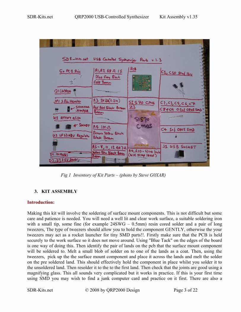
( ) Inventory of Kit parts is highly recommended – see Fig 1 below.Caution: Please observe antistatic precautions for semiconductor devices Do not remove Si570 device from anti-static bag until needed
Note: If you have a question about the kit. please contact Jan G0BBL via sdrkits @ gmail.com (remove all spaces in email address)
SDR-Kits.net © 2008 by QRP2000 Design Page 2 of 22
SDR-Kits.net QRP2000 USB-Controlled Synthesizer Kit Assembly v1.35
Fig 1 Inventory of Kit Parts – (photo by Steve G0XAR)
3. KIT ASSEMBLY
Introduction:
Making this kit will involve the soldering of surface mount components. This is not difficult but some care and patience is needed. You will need a well lit and clear work surface, a suitable soldering iron with a small tip, some fine (for example 24SWG – 0.5mm) resin cored solder and a pair of long tweezers, The type of tweezers should allow you to hold the component GENTLY, otherwise the your tweezers may act as a rocket launcher for tiny SMD parts!!. Firstly make sure that the PCB is held securely to the work surface so it does not move around. Using "Blue Tack" on the edges of the board is one way of doing this. Then identify the pair of lands on the pcb that the surface mount component will be soldered to. Melt a small blob of solder on to one of the lands as a coat. Then, using the tweezers, pick up the the surface mount component and place it across the lands and melt the solder on the pre soldered land. This should effectively hold the component in place whilst you solder it to the unsoldered land. Then resolder it to the to the first land. Then check that the joints are good using a magnifying glass. This all sounds very complicated but it works in practice. If this is your first time using SMD you may wish to find a junk computer card and practice on it first. There are also a
SDR-Kits.net © 2008 by QRP2000 Design Page 3 of 22
SDR-Kits.net QRP2000 USB-Controlled Synthesizer Kit Assembly v1.35
number of excellent tutorials on the internet - and no you do not need an oven or an SM workstation. An ordinary soldering iron (preferably temperature controlled is good enough.Good luck – Viel spass – Veel plezier -
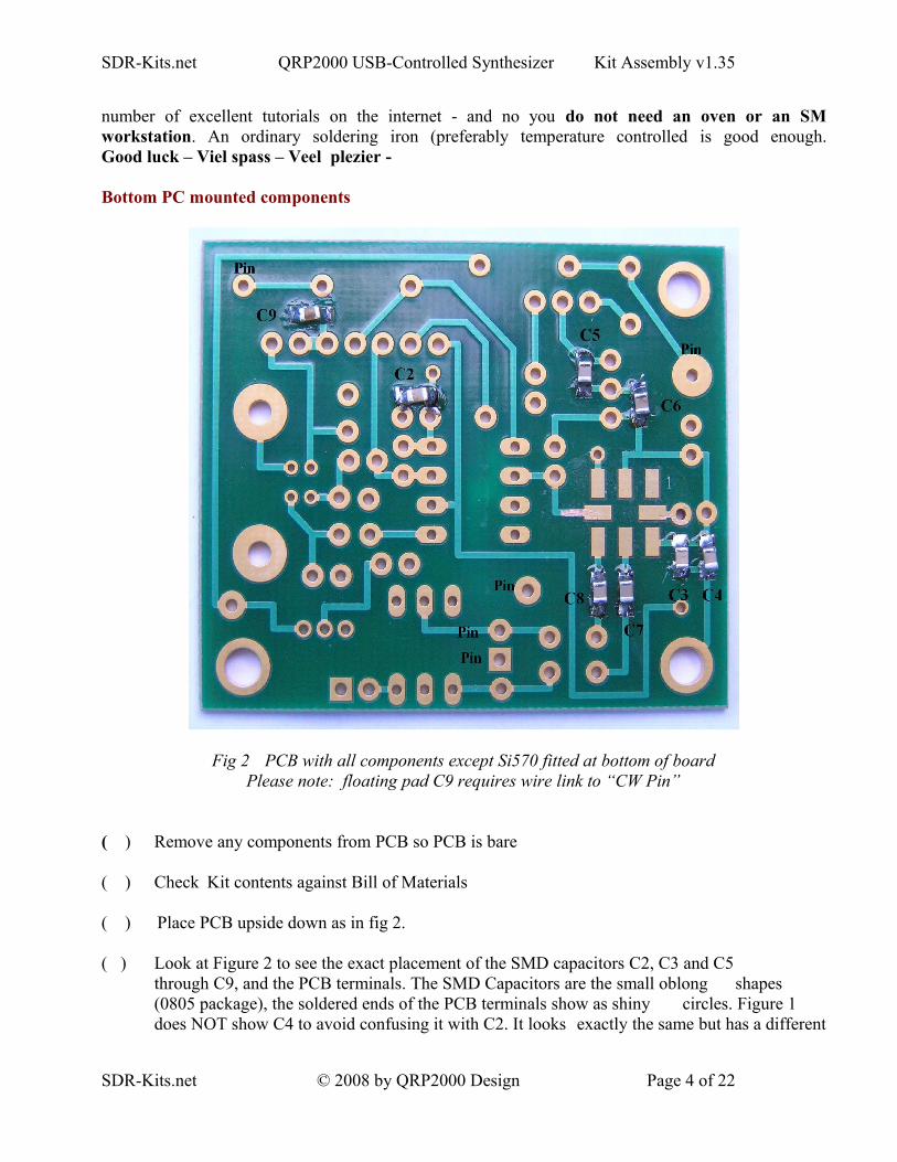
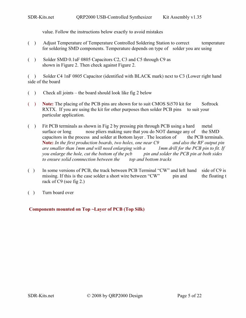
Bottom PC mounted components
Fig 2 PCB with all components except Si570 fitted at bottom of boardPlease note: floating pad C9 requires wire link to “CW Pin”
( ) Remove any components from PCB so PCB is bare
( ) Check Kit contents against Bill of Materials
( ) Place PCB upside down as in fig 2.
( ) Look at Figure 2 to see the exact placement of the SMD capacitors C2, C3 and C5 through C9, and the PCB terminals. The SMD Capacitors are the small oblong shapes (0805 package), the soldered ends of the PCB terminals show as shiny circles. Figure 1 does NOT show C4 to avoid confusing it with C2. It looks exactly the same but has a different
SDR-Kits.net © 2008 by QRP2000 Design Page 4 of 22
SDR-Kits.net QRP2000 USB-Controlled Synthesizer Kit Assembly v1.35
value. Follow the instructions below exactly to avoid mistakes
( ) Adjust Temperature of Temperature Controlled Soldering Station to correct temperature for soldering SMD components. Temperature depends on type of solder you are using
( ) Solder SMD 0.1uF 0805 Capacitors C2, C3 and C5 through C9 asshown in Figure 2. Then check against Figure 2.
( ) Solder C4 1nF 0805 Capacitor (identified with BLACK mark) next to C3 (Lower right hand side of the board
( ) Check all joints – the board should look like fig 2 below
( ) Note: The placing of the PCB pins are shown for to suit CMOS Si570 kit for Softrock RXTX. If you are using the kit for other purposes then solder PCB pins to suit your particular application.
( ) Fit PCB terminals as shown in Fig 2 by pressing pin through PCB using a hard metal
surface or long nose pliers making sure that you do NOT damage any of the SMD capacitors in the process and solder at Bottom layer . The location of the PCB terminals. Note: In the first production boards, two holes, one near C9 and also the RF output pin are smaller than 1mm and will need enlarging with a 1mm drill for the PCB pin to fit. If you enlarge the hole, cut the bottom of the pcb pin and solder the PCB pin at both sides to ensure solid connnection between the top and bottom tracks
( ) In some versions of PCB, the track between PCB Terminal “CW” and left hand side of C9 is missing. If this is the case solder a short wire between “CW” pin and the floating track of C9 (see fig 2.)
( ) Turn board over
Components mounted on Top ~Layer of PCB (Top Silk)
SDR-Kits.net © 2008 by QRP2000 Design Page 5 of 22
SDR-Kits.net QRP2000 USB-Controlled Synthesizer Kit Assembly v1.35
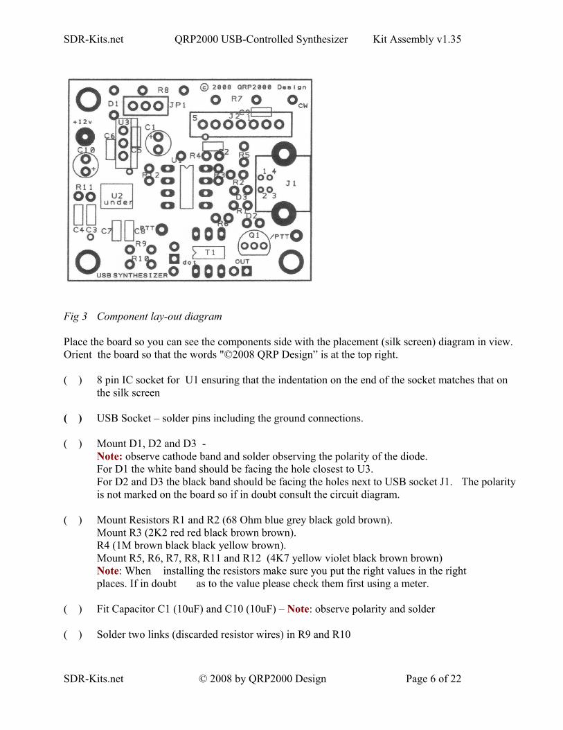
Fig 3 Component lay-out diagram
Place the board so you can see the components side with the placement (silk screen) diagram in view. Orient the board so that the words "©2008 QRP Design” is at the top right.
( ) 8 pin IC socket for U1 ensuring that the indentation on the end of the socket matches that on the silk screen
( ) USB Socket – solder pins including the ground connections.
( ) Mount D1, D2 and D3 - Note: observe cathode band and solder observing the polarity of the diode. For D1 the white band should be facing the hole closest to U3. For D2 and D3 the black band should be facing the holes next to USB socket J1. The polarity is not marked on the board so if in doubt consult the circuit diagram.
( ) Mount Resistors R1 and R2 (68 Ohm blue grey black gold brown).Mount R3 (2K2 red red black brown brown).R4 (1M brown black black yellow brown).Mount R5, R6, R7, R8, R11 and R12 (4K7 yellow violet black brown brown) Note: When installing the resistors make sure you put the right values in the right places. If in doubt as to the value please check them first using a meter.
( ) Fit Capacitor C1 (10uF) and C10 (10uF) – Note: observe polarity and solder
( ) Solder two links (discarded resistor wires) in R9 and R10
SDR-Kits.net © 2008 by QRP2000 Design Page 6 of 22
SDR-Kits.net QRP2000 USB-Controlled Synthesizer Kit Assembly v1.35
( ) Caution: when handling semiconductors observe anti-static precautions:Preferably wear anti-static Strap or touch unpainted metal ground before handling semiconductors
( ) Fit transistor Q1 – Note: observe position against top silk and solder
( ) Fit U3 (LF33ABV) – Note: observe correct position against top silk and solder
( ) Fit Connector JP1 (3 pin) and solder
( ) Fit 2 pin Output Connector and solder –
LVDS Transformer T1 (supplied with complete Si570 LVDS Kit only
( ) Cut enamelled wire in 3 pieces of 18 cm (7 inches) each and twist uniformly to 4 turns per cm
( ) Wind 5 turns trifiliar on 43BN2402 supplied.
( ) Scrape and tin end of enamelled wire and fit T1 on PCB if required.
Interim Test Procedure
Note: Jumper 1 is used to set the source of the power for the board. If it is next to the diode the source is supplied from the external power line, if in the alternative position the power is supplied from the USB port
( ) Set Jumper JP1 to pin next to Diode D1
( ) Connect 5-12V DC Power to PCB – Note: observe polarity
( ) Check Voltage on U3 pin 3 to Ground - Note: reading should be 3.3V +/- 0.1V
( ) Remove Power to PCB
( ) Caution: observe anti-static precautions handling semiconductor
( ) Plug ATTiny45 U1 into IC holder – pin 1 should be aligned towards U1 on the top silk
( ) Connect USB Synthesizer to USB socket of a Personal Computer and measure voltage between U1 Pin 8. Reading should be 4.9 – 5.1V
( ) Disconnect USB cable from USB Synthesizer
Final assembly of Si570 Device
( ) Caution: observe antistatic precautions handling semiconductors
SDR-Kits.net © 2008 by QRP2000 Design Page 7 of 22
SDR-Kits.net QRP2000 USB-Controlled Synthesizer Kit Assembly v1.35
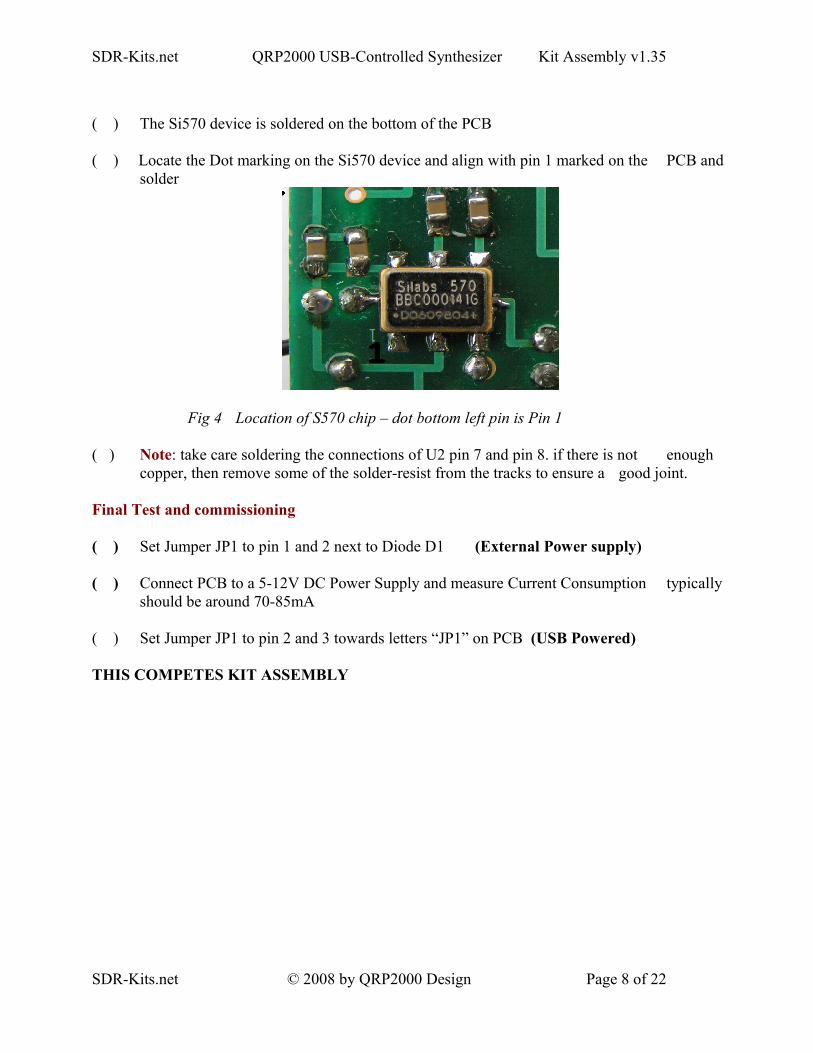
( ) The Si570 device is soldered on the bottom of the PCB
( ) Locate the Dot marking on the Si570 device and align with pin 1 marked on the PCB and solder
Fig 4 Location of S570 chip – dot bottom left pin is Pin 1
( ) Note: take care soldering the connections of U2 pin 7 and pin 8. if there is not enough copper, then remove some of the solder-resist from the tracks to ensure a good joint.
Final Test and commissioning
( ) Set Jumper JP1 to pin 1 and 2 next to Diode D1 (External Power supply)
( ) Connect PCB to a 5-12V DC Power Supply and measure Current Consumption typically should be around 70-85mA
( ) Set Jumper JP1 to pin 2 and 3 towards letters “JP1” on PCB (USB Powered)
THIS COMPETES KIT ASSEMBLY
SDR-Kits.net © 2008 by QRP2000 Design Page 8 of 22
SDR-Kits.net QRP2000 USB-Controlled Synthesizer Kit Assembly v1.35
4. DRIVER INSTALLATION PROCEDURE MICROSOFT XP
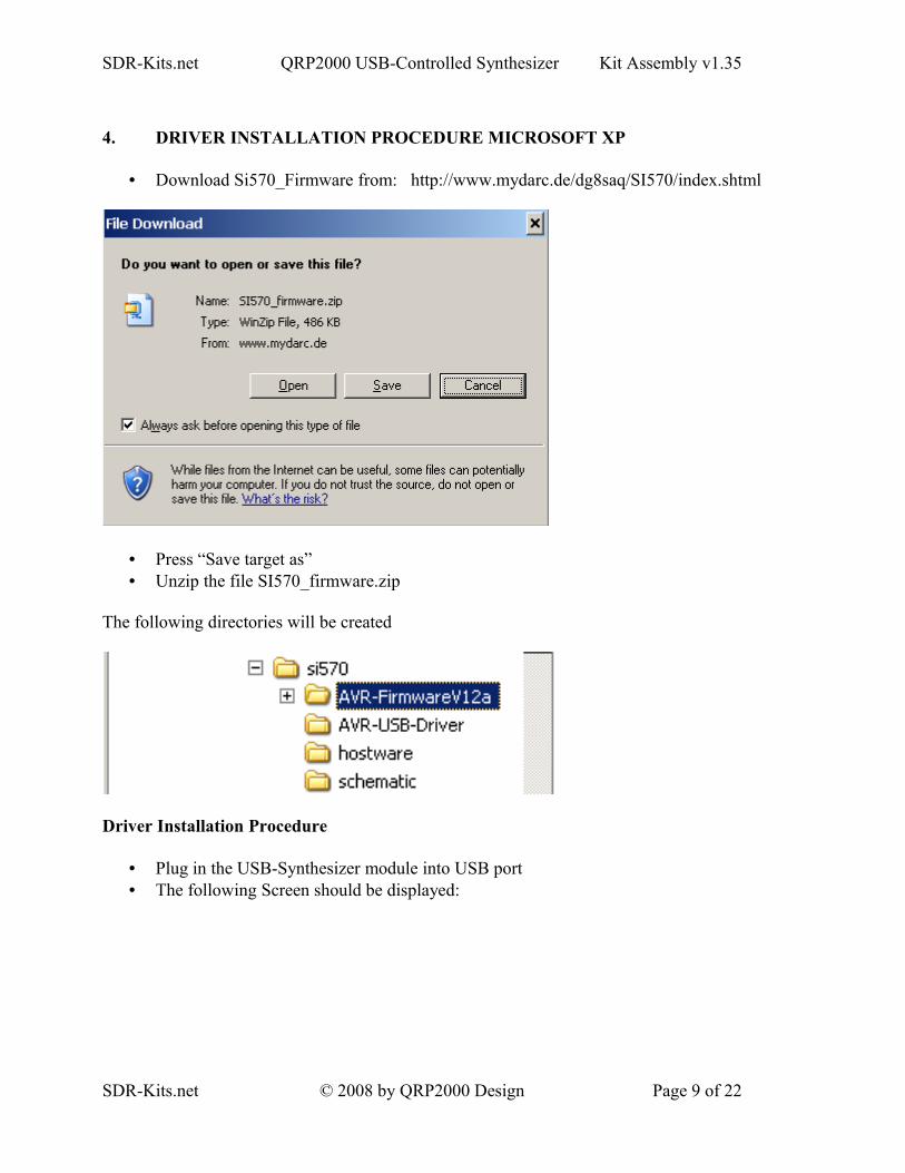
• Download Si570_Firmware from: http://www.mydarc.de/dg8saq/SI570/index.shtml
• Press “Save target as”• Unzip the file SI570_firmware.zip
The following directories will be created
Driver Installation Procedure
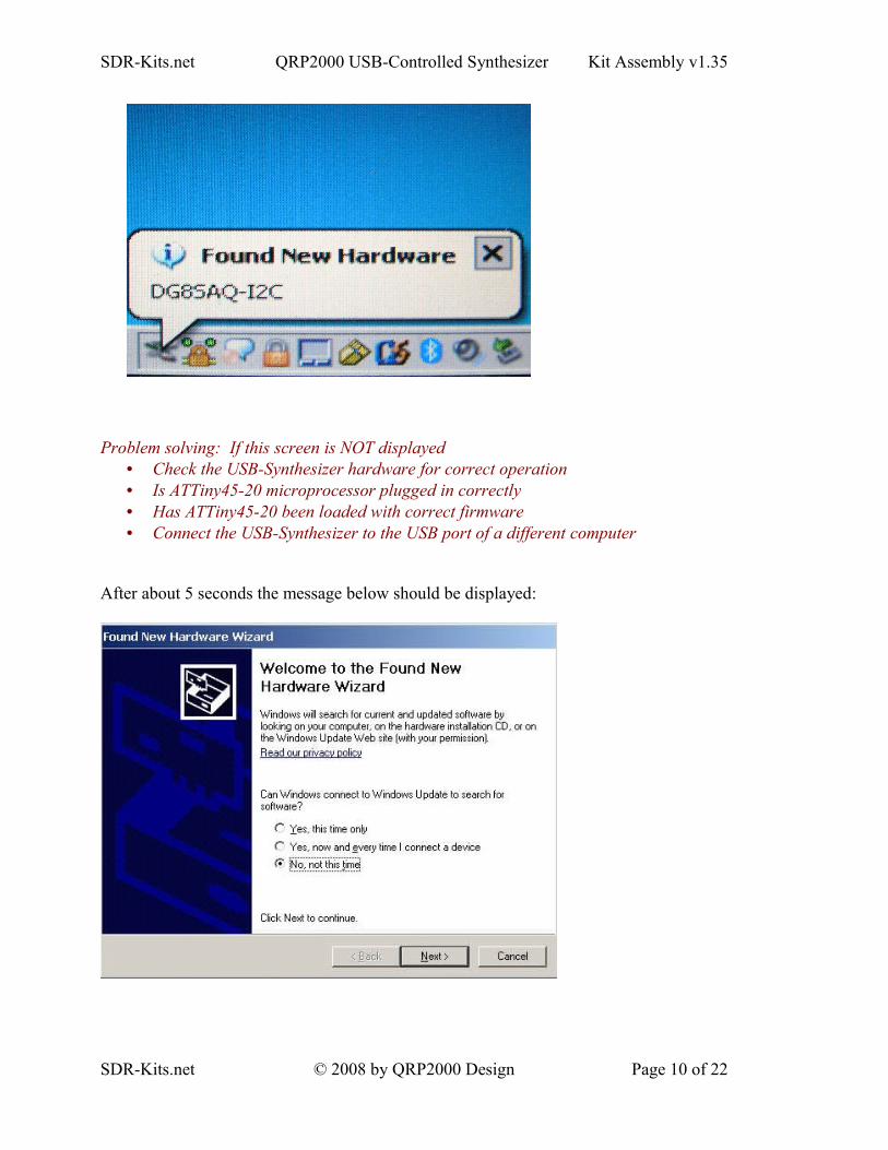
• Plug in the USB-Synthesizer module into USB port• The following Screen should be displayed:
SDR-Kits.net © 2008 by QRP2000 Design Page 9 of 22
SDR-Kits.net QRP2000 USB-Controlled Synthesizer Kit Assembly v1.35
Problem solving: If this screen is NOT displayed• Check the USB-Synthesizer hardware for correct operation• Is ATTiny45-20 microprocessor plugged in correctly• Has ATTiny45-20 been loaded with correct firmware• Connect the USB-Synthesizer to the USB port of a different computer
After about 5 seconds the message below should be displayed:
SDR-Kits.net © 2008 by QRP2000 Design Page 10 of 22
SDR-Kits.net QRP2000 USB-Controlled Synthesizer Kit Assembly v1.35
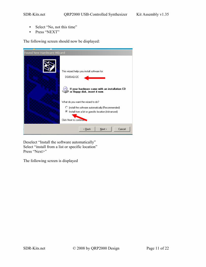
• Select “No, not this time”• Press “NEXT”
The following screen should now be displayed:
Deselect “Install the software automatically”Select “install from a list or specific location” Press “Next>”
The following screen is displayed
SDR-Kits.net © 2008 by QRP2000 Design Page 11 of 22

SDR-Kits.net QRP2000 USB-Controlled Synthesizer Kit Assembly v1.35
• Deselect “Search removable Media”• Select “Include this location in the search”• Press “Browse”• Select Folder AVR-USB-Driver as shown below
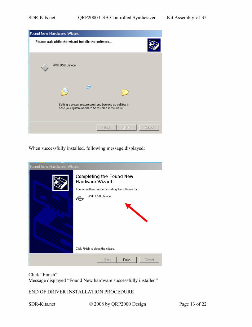
• Click “Ok”• Press “Next>”• Software is being installed
SDR-Kits.net © 2008 by QRP2000 Design Page 12 of 22
SDR-Kits.net QRP2000 USB-Controlled Synthesizer Kit Assembly v1.35
When successfully installed, following message displayed:
Click “Finish”Message displayed “Found New hardware successfully installed”
END OF DRIVER INSTALLATION PROCEDURE
SDR-Kits.net © 2008 by QRP2000 Design Page 13 of 22
SDR-Kits.net QRP2000 USB-Controlled Synthesizer Kit Assembly v1.35
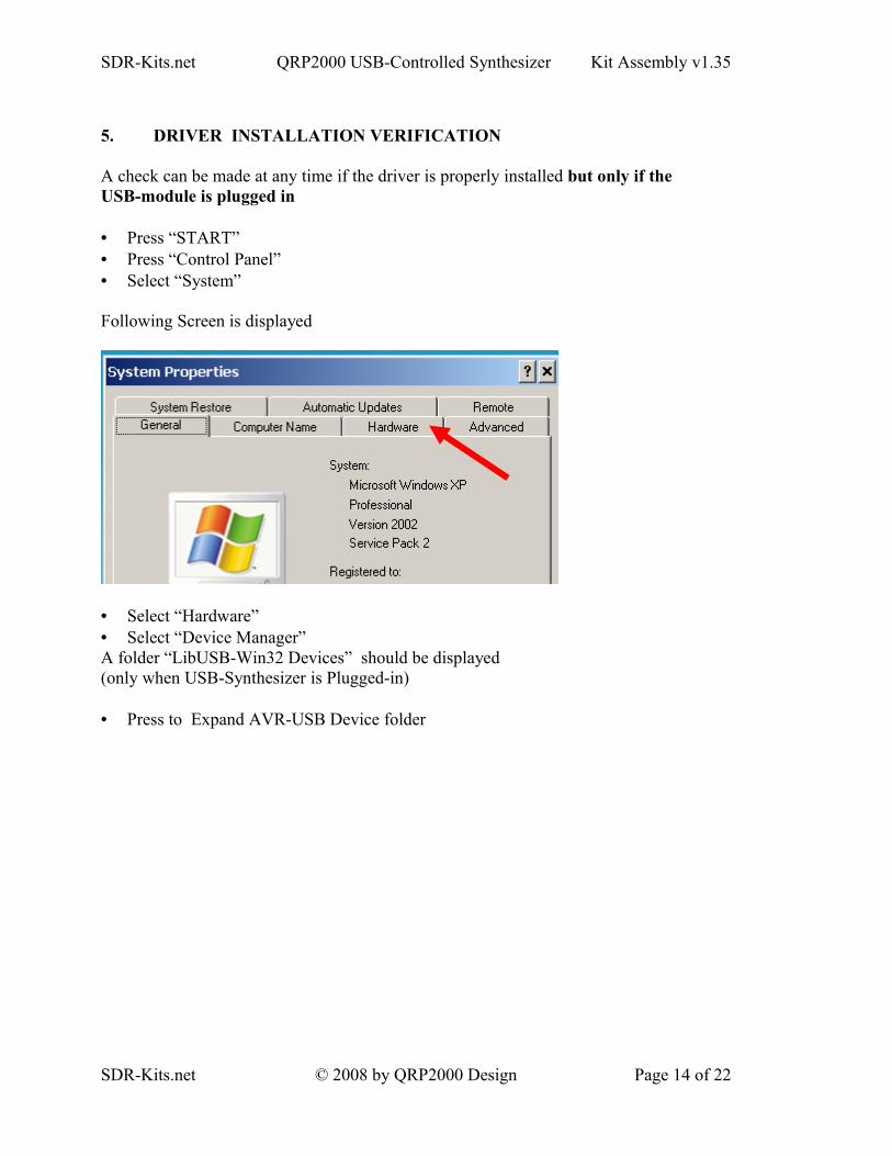
5. DRIVER INSTALLATION VERIFICATION
A check can be made at any time if the driver is properly installed but only if theUSB-module is plugged in
• Press “START”• Press “Control Panel”• Select “System”
Following Screen is displayed
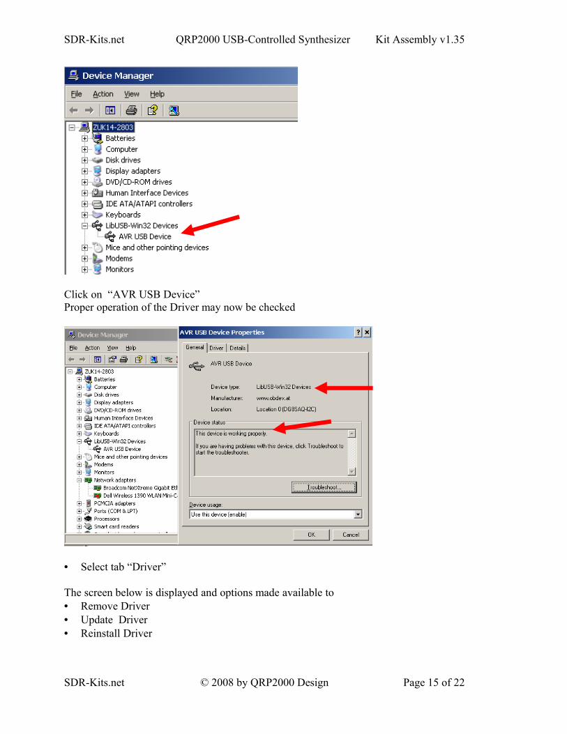
• Select “Hardware”• Select “Device Manager”A folder “LibUSB-Win32 Devices” should be displayed(only when USB-Synthesizer is Plugged-in)
• Press to Expand AVR-USB Device folder
SDR-Kits.net © 2008 by QRP2000 Design Page 14 of 22
SDR-Kits.net QRP2000 USB-Controlled Synthesizer Kit Assembly v1.35
Click on “AVR USB Device”Proper operation of the Driver may now be checked
• Select tab “Driver”
The screen below is displayed and options made available to • Remove Driver• Update Driver• Reinstall Driver
SDR-Kits.net © 2008 by QRP2000 Design Page 15 of 22
SDR-Kits.net QRP2000 USB-Controlled Synthesizer Kit Assembly v1.35
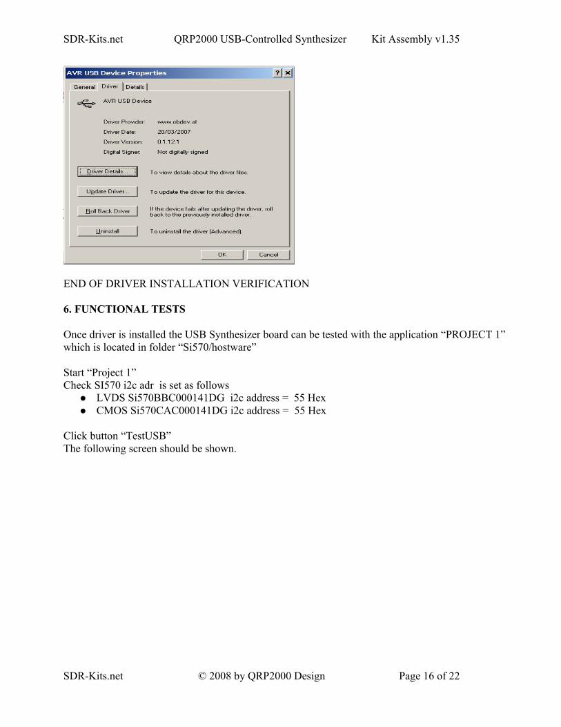
END OF DRIVER INSTALLATION VERIFICATION
6. FUNCTIONAL TESTS
Once driver is installed the USB Synthesizer board can be tested with the application “PROJECT 1” which is located in folder “Si570/hostware”
Start “Project 1”Check SI570 i2c adr is set as follows
LVDS Si570BBC000141DG i2c address = 55 Hex CMOS Si570CAC000141DG i2c address = 55 Hex
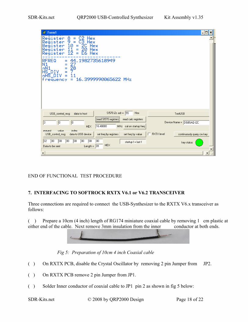
Click button “TestUSB” The following screen should be shown.
SDR-Kits.net © 2008 by QRP2000 Design Page 16 of 22
SDR-Kits.net QRP2000 USB-Controlled Synthesizer Kit Assembly v1.35
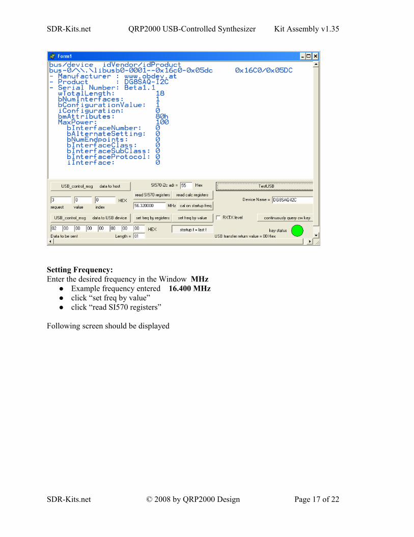
Setting Frequency:Enter the desired frequency in the Window MHz
Example frequency entered 16.400 MHz click “set freq by value” click “read SI570 registers”
Following screen should be displayed
SDR-Kits.net © 2008 by QRP2000 Design Page 17 of 22
SDR-Kits.net QRP2000 USB-Controlled Synthesizer Kit Assembly v1.35
END OF FUNCTIONAL TEST PROCEDURE
7. INTERFACING TO SOFTROCK RXTX V6.1 or V6.2 TRANSCEIVER
Three connections are required to connect the USB-Synthesizer to the RXTX V6.x transceiver as follows:
( ) Prepare a 10cm (4 inch) length of RG174 miniature coaxial cable by removing 1 cm plastic at either end of the cable. Next remove 3mm insulation from the inner conductor at both ends.
Fig 5: Preparation of 10cm 4 inch Coaxial cable
( ) On RXTX PCB, disable the Crystal Oscillator by removing 2 pin Jumper from JP2.
( ) On RXTX PCB remove 2 pin Jumper from JP1.
( ) Solder Inner conductor of coaxial cable to JP1 pin 2 as shown in fig 5 below:
SDR-Kits.net © 2008 by QRP2000 Design Page 18 of 22
SDR-Kits.net QRP2000 USB-Controlled Synthesizer Kit Assembly v1.35
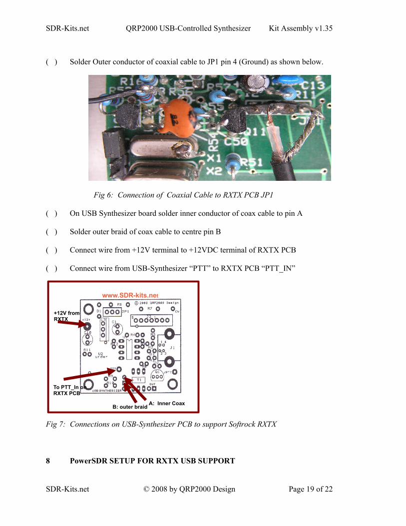
( ) Solder Outer conductor of coaxial cable to JP1 pin 4 (Ground) as shown below.
Fig 6: Connection of Coaxial Cable to RXTX PCB JP1
( ) On USB Synthesizer board solder inner conductor of coax cable to pin A
( ) Solder outer braid of coax cable to centre pin B
( ) Connect wire from +12V terminal to +12VDC terminal of RXTX PCB
( ) Connect wire from USB-Synthesizer “PTT” to RXTX PCB “PTT_IN”
Fig 7: Connections on USB-Synthesizer PCB to support Softrock RXTX
8 PowerSDR SETUP FOR RXTX USB SUPPORT
SDR-Kits.net © 2008 by QRP2000 Design Page 19 of 22
A: Inner CoaxB: outer braid
+12V from RXTX
www.SDR-kits.net
To PTT_In on RXTX PCB
SDR-Kits.net QRP2000 USB-Controlled Synthesizer Kit Assembly v1.35
( ) Download PowerSDR application from sourceforge http://powersdr-sr40.sourceforge.net/ and install as per instructions
Beta versions may be posted on www.SDR-Kits.net website
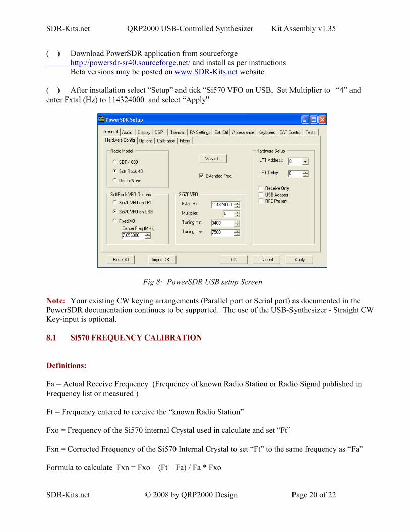
( ) After installation select “Setup” and tick “Si570 VFO on USB, Set Multiplier to “4” and enter Fxtal (Hz) to 114324000 and select “Apply”
Fig 8: PowerSDR USB setup Screen
Note: Your existing CW keying arrangements (Parallel port or Serial port) as documented in the PowerSDR documentation continues to be supported. The use of the USB-Synthesizer - Straight CW Key-input is optional.
8.1 Si570 FREQUENCY CALIBRATION
Definitions:
Fa = Actual Receive Frequency (Frequency of known Radio Station or Radio Signal published in Frequency list or measured )
Ft = Frequency entered to receive the “known Radio Station”
Fxo = Frequency of the Si570 internal Crystal used in calculate and set “Ft”
Fxn = Corrected Frequency of the Si570 Internal Crystal to set “Ft” to the same frequency as “Fa”
Formula to calculate Fxn = Fxo – (Ft – Fa) / Fa * Fxo
SDR-Kits.net © 2008 by QRP2000 Design Page 20 of 22
SDR-Kits.net QRP2000 USB-Controlled Synthesizer Kit Assembly v1.35
Example = Fxo = 114,300.500 kHzFa = 10,000.000 kHz (WWV reception on 10 MHz)Ft = 9,995.355 kHz Frequency set to receive WWV
Fxn = 114,353.593 (Corrected Crystal frequency – which should be stored (in Hz) for future use by
the program)
9 Rocky V3.5 Setup
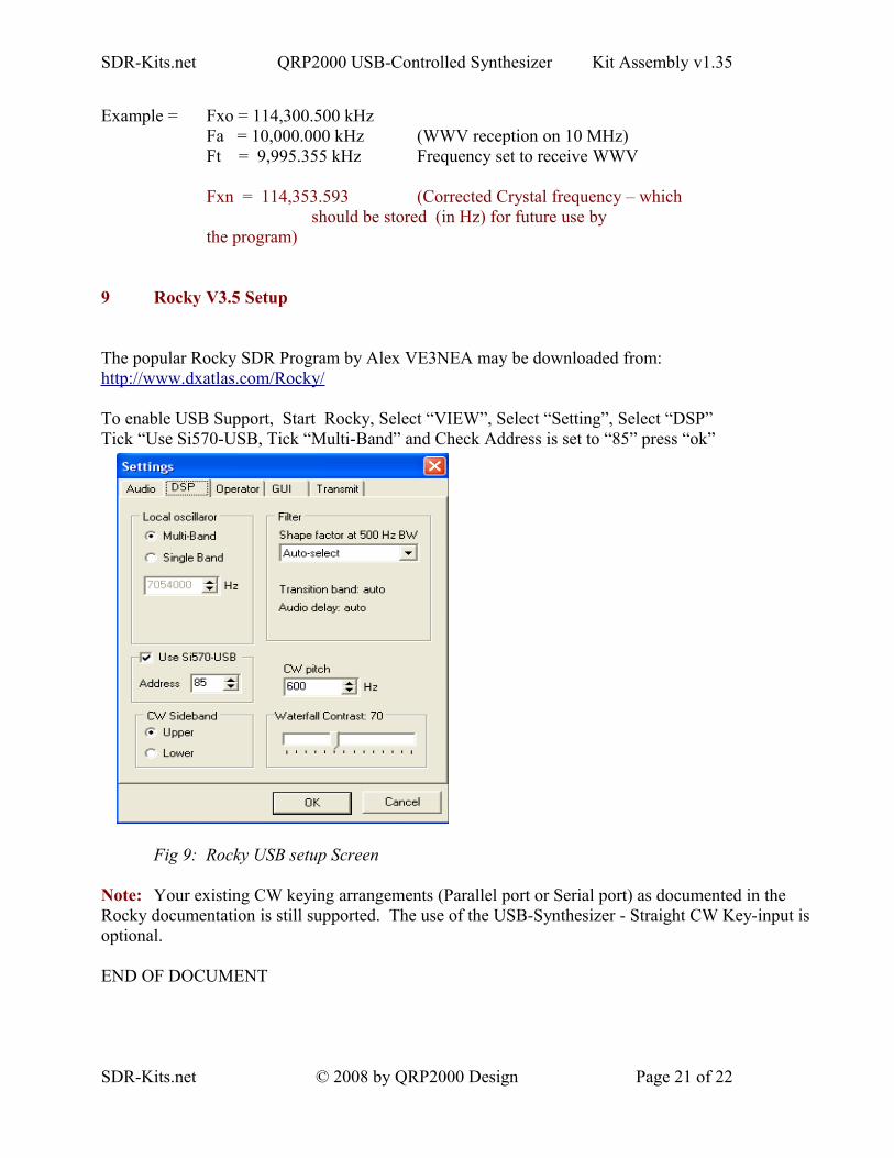
The popular Rocky SDR Program by Alex VE3NEA may be downloaded from:http://www.dxatlas.com/Rocky/
To enable USB Support, Start Rocky, Select “VIEW”, Select “Setting”, Select “DSP”Tick “Use Si570-USB, Tick “Multi-Band” and Check Address is set to “85” press “ok”
Fig 9: Rocky USB setup Screen
Note: Your existing CW keying arrangements (Parallel port or Serial port) as documented in the Rocky documentation is still supported. The use of the USB-Synthesizer - Straight CW Key-input is optional.
END OF DOCUMENT
SDR-Kits.net © 2008 by QRP2000 Design Page 21 of 22
SDR-Kits.net QRP2000 USB-Controlled Synthesizer Kit Assembly v1.35
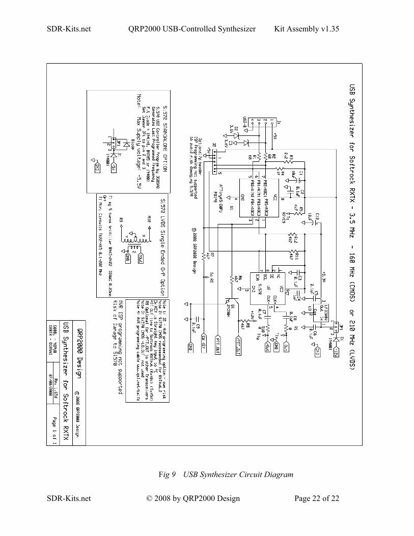
Fig 9 USB Synthesizer Circuit Diagram
SDR-Kits.net © 2008 by QRP2000 Design Page 22 of 22