usb devices -...
TRANSCRIPT
USB Devices
Introduction The MSP430 makes an ideal USB device: ultra-low power, rich integration of peripherals and it’s inexpensive. Do you want to make a Human Interface Device product? Maybe a sensor, such as a barcode reader, that needs to be both low-power (when collecting data), but also capable of ‘dumping’ its data via USB to a computer. Dream big, we’ve got the devices, tools, and software to help you make them come true.
Learning Objectives
Objectives
- Draw a diagram that defines the basic operation of USB serial communications
- USB classes:- List the 3 supported by MSP430 devices- When to select one versus another
- Enumerate 2 ways, using TI’s USB API to respond to a system’s USB connection state
- To NOT cover every aspect of USB- Write a program to talk over the USB serial bus
using the provided API stack
MSP430 Design Workshop - USB Devices 10 - 1
Introduction
Chapter Topics USB Devices .............................................................................................................................. 10-1
Introduction ............................................................................................................................. 10-1 What is USB? .......................................................................................................................... 10-3 MSP430's USB Support .......................................................................................................... 10-7
USB Fees .......................................................................................................................... 10-13 How USB Works ................................................................................................................... 10-15
Pipes and Endpoints ......................................................................................................... 10-16 USB Transfer Types .......................................................................................................... 10-19 The USB Frame ................................................................................................................ 10-20
Descriptions and Classes ...................................................................................................... 10-22 Quick Overview of MSP430’s USB Stack ............................................................................. 10-28 ABC’s of USB ........................................................................................................................ 10-31
A. Plan Your System ......................................................................................................... 10-31 B. Connect & Enumerate .................................................................................................. 10-32 C. Managing my App & Transferring Data ........................................................................ 10-34
Final Thoughts ...................................................................................................................... 10-37 Lab Exercise ......................................................................................................................... 10-39
10 - 2 MSP430 Design Workshop - USB Devices
What is USB?
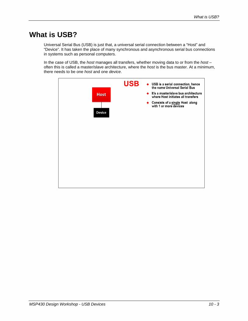
What is USB? Universal Serial Bus (USB) is just that, a universal serial connection between a “Host” and “Device”. It has taken the place of many synchronous and asynchronous serial bus connections in systems such as personal computers.
In the case of USB, the host manages all transfers, whether moving data to or from the host – often this is called a master/slave architecture, where the host is the bus master. At a minimum, there needs to be one host and one device.
MSP430 Design Workshop - USB Devices 10 - 3
What is USB?
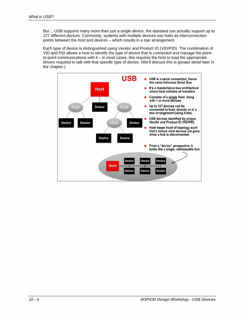
But… USB supports many more than just a single device, the standard can actually support up to 127 different devices. Commonly, systems with multiple devices use hubs as interconnection points between the host and devices – which results in a star arrangement.
Each type of device is distinguished using Vendor and Product ID (VID/PID). The combination of VID and PID allows a host to identify the type of device that is connected and manage the point-to-point communications with it – in most cases, this requires the host to load the appropriate drivers required to talk with that specific type of device. (We’ll discuss this is greater detail later in the chapter.)
10 - 4 MSP430 Design Workshop - USB Devices
What is USB?
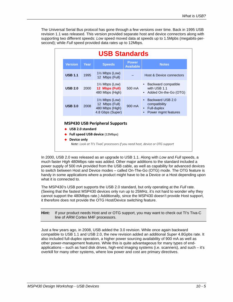
The Universal Serial Bus protocol has gone through a few versions over time. Back in 1995 USB revision 1.1 was released. This version provided separate host and device connectors along with supporting two different speeds: Low speed moved data at speeds up to 1.5Mpbs (megabits-per-second); while Full speed provided data rates up to 12Mbps.
USB Standards
aSt430 USB teripheral Supports USB 2.0 standard Full speed USB device (12abps) Device only
Note: Look at TI’s TivaC processors if you need host, device or OTG support
Version Year Speeds Power Available Notes
USB 1.1 1995 1½ Mbps (Low)12 Mbps (Full) – Host & Device connectors
USB 2.0 20001½ Mbps (Low)12 Mbps (Full)480 Mbps (High)
500 mA• Backward compatible
with USB 1.1• Added On-the-Go (OTG)
USB 3.0 2008
1½ Mbps (Low)12 Mbps (Full)
480 Mbps (High)4.8 Gbps (Super)
900 mA
• Backward USB 2.0 compatibility
• Full-duplex• Power mgmt features
In 2000, USB 2.0 was released as an upgrade to USB 1.1. Along with Low and Full speeds, a much faster High 480Mbps rate was added. Other major additions to the standard included a power supply of 500 mA provided from the USB cable, as well as capability for advanced devices to switch between Host and Device modes – called On-The-Go (OTG) mode. The OTG feature is handy in some applications where a product might have to be a Device or a Host depending upon what it is connected to.
The MSP430’s USB port supports the USB 2.0 standard, but only operating at the Full rate. (Seeing that the fastest MSP430 devices only run up to 25MHz, it’s not hard to wonder why they cannot support the 480Mbps rate.) Additionally, since the MSP430 doesn’t provide Host support, it therefore does not provide the OTG Host/Device switching feature.
Hint: If your product needs Host and or OTG support, you may want to check out TI’s Tiva-C line of ARM Cortex M4F processors.
Just a few years ago, in 2008, USB added the 3.0 revision. While once again backward compatible to USB 1.1 and USB 2.0, the new revision added an additional Super 4.8Gpbs rate. It also included full-duplex operation, a higher power sourcing availability of 900 mA as well as other power-management features. While this is quite advantageous for many types of end-applications – such as hard disk drives, high-end imaging systems (i.e. scanners), and such – it’s overkill for many other systems, where low power and cost are primary directives.
MSP430 Design Workshop - USB Devices 10 - 5
What is USB?
Bus standards, such as USB, contain a variety of layers. While these physical and data specifications are important, exploring them in great detail is outside the scope of this chapter.
On the following slide, we’ll introduce a couple basic features of the physical layer – that is, of the USB cable. Later on in the chapter, we will discuss some of the details regarding data and software layers.
Bottom Line: We have tried to approach USB, in this chapter, from a pragmatic perspective. That is, rather than examining the details of the specification, we want to figure out how to use TI’s devices and tooling in order to just get something running.
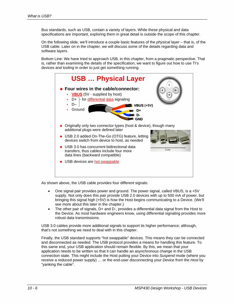
USB … Physical Layer Four wires in the cable/connector:
VBUS (5V - supplied by host) D+ for differential data signaling D– Ground
Originally only two connector types (host & device), though many additional plugs were defined later
USB 2.0 added On-The-Go (OTG) feature, lettingdevices switch from device to host, as needed
USB 3.0 has concurrent bidirectional data transfers, thus cables include four more data lines (backward compatible)
USB devices are hot swappable
D-D+
GND
VBUS (+5V)
R
Y
B
Br
As shown above, the USB cable provides four different signals:
• One signal pair provides power and ground. The power signal, called VBUS, is a +5V supply. Not only does this pair provide USB 2.0 devices with up to 500 mA of power, but bringing this signal high (+5V) is how the Host begins communicating to a Device. (We’ll see more about this later in the chapter.)
• The other pair of signals, D+ and D-, provides a differential data signal from the Host to the Device. As most hardware engineers know, using differential signaling provides more robust data transmissions.
USB 3.0 cables provide more additional signals to support its higher performance; although, that’s not something we need to deal with in this chapter.
Finally, the USB standard supports “hot swappable” devices. This means they can be connected and disconnected as needed. The USB protocol provides a means for handling this feature. To this same end, your USB application should remain flexible. By this, we mean that your application needs to be written so that it can handle an asynchronous change in the USB connection state. This might include the Host putting your Device into Suspend mode (where you receive a reduced power supply) … or the end-user disconnecting your Device from the Host by “yanking the cable”.
10 - 6 MSP430 Design Workshop - USB Devices
MSP430's USB Support
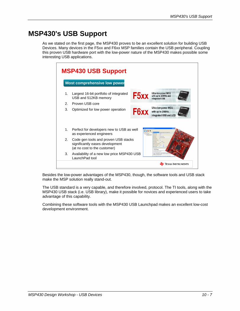
MSP430's USB Support As we stated on the first page, the MSP430 proves to be an excellent solution for building USB Devices. Many devices in the F5xx and F6xx MSP families contain the USB peripheral. Coupling this proven USB hardware port with the low-power nature of the MSP430 makes possible some interesting USB applications.
MSP430 USB Support
1. Largest 16-bit portfolio of integrated USB and 512KB memory
2. Proven USB core3. Optimized for low power operation
1. Perfect for developers new to USB as well as experienced engineers
2. Code gen tools and proven USB stacks significantly eases development (at no cost to the customer)
3. Availability of a new low price MSP430 USB LaunchPad tool
Most comprehensive low power MCU USB portfolio
Easy USB coding for developers
Besides the low-power advantages of the MSP430, though, the software tools and USB stack make the MSP solution really stand-out.
The USB standard is a very capable, and therefore involved, protocol. The TI tools, along with the MSP430 USB stack (i.e. USB library), make it possible for novices and experienced users to take advantage of this capability.
Combining these software tools with the MSP430 USB Launchpad makes an excellent low-cost development environment.
MSP430 Design Workshop - USB Devices 10 - 7
MSP430's USB Support
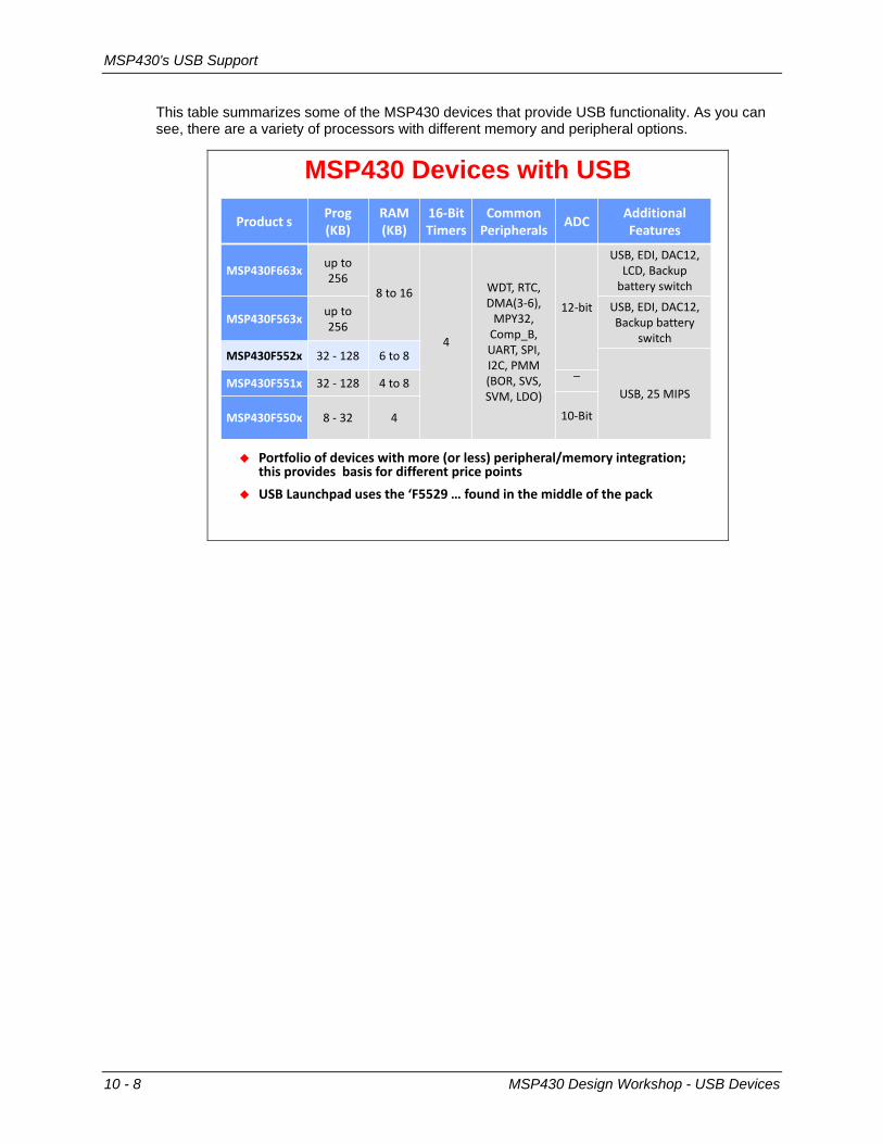
This table summarizes some of the MSP430 devices that provide USB functionality. As you can see, there are a variety of processors with different memory and peripheral options.
MSP430 Devices with USB
troduct s trog(KB)
wAa(KB)
16-Bit Timers
Common teripherals ADC Additional
Features
aSt430F663x up to 256
8 to 16
4
WDT, wTC, DMA(3-6),
MtY32, Comp_B, UAwT, StI, I2C, tMM (Bhw, SVS, SVM, LDh)
12-bit
USB, EDI, DAC12, LCD, Backup
battery switch
aSt430F563x up to 256
USB, EDI, DAC12, Backup battery
switchaSt430F552x 32 - 128 6 to 8
USB, 25 MItSaSt430F551x 32 - 128 4 to 8 ‾
10-BitaSt430F550x 8 - 32 4
tortfolio of devices with more (or less) peripheral/memory integration; this provides basis for different price points
USB Launchpad uses the ‘F5529 … found in the middle of the pack
10 - 8 MSP430 Design Workshop - USB Devices
MSP430's USB Support
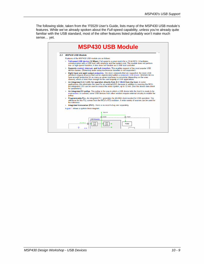
The following slide, taken from the ‘F5529 User’s Guide, lists many of the MSP430 USB module’s features. While we’ve already spoken about the Full-speed capability, unless you’re already quite familiar with the USB standard, most of the other features listed probably won’t make much sense… yet.
MSP430 USB Module
MSP430 Design Workshop - USB Devices 10 - 9
MSP430's USB Support
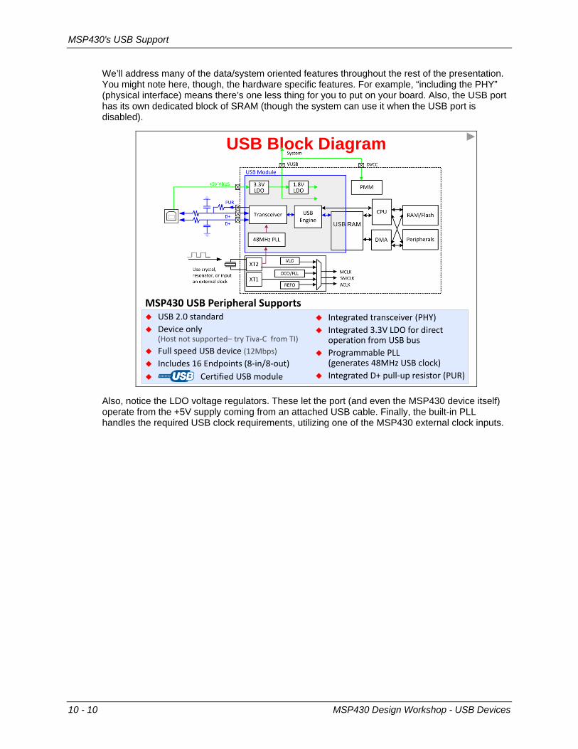
We’ll address many of the data/system oriented features throughout the rest of the presentation. You might note here, though, the hardware specific features. For example, “including the PHY” (physical interface) means there’s one less thing for you to put on your board. Also, the USB port has its own dedicated block of SRAM (though the system can use it when the USB port is disabled).
USB Block Diagram
aSt430 USB teripheral Supports USB 2.0 standard Device only
(Host not supported– try Tiva-C from TI) Full speed USB device (12Mbps) Includes 16 Endpoints (8-in/8-out) Certified USB module
Integrated transceiver (tHY) Integrated 3.3V LDh for direct
operation from USB bus trogrammable tLL
(generates 48MHz USB clock) Integrated D+ pull-up resistor (tUw)
Also, notice the LDO voltage regulators. These let the port (and even the MSP430 device itself) operate from the +5V supply coming from an attached USB cable. Finally, the built-in PLL handles the required USB clock requirements, utilizing one of the MSP430 external clock inputs.
10 - 10 MSP430 Design Workshop - USB Devices
MSP430's USB Support
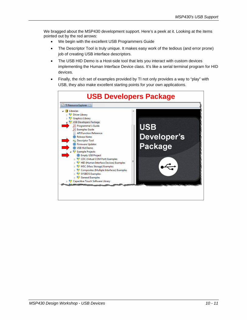
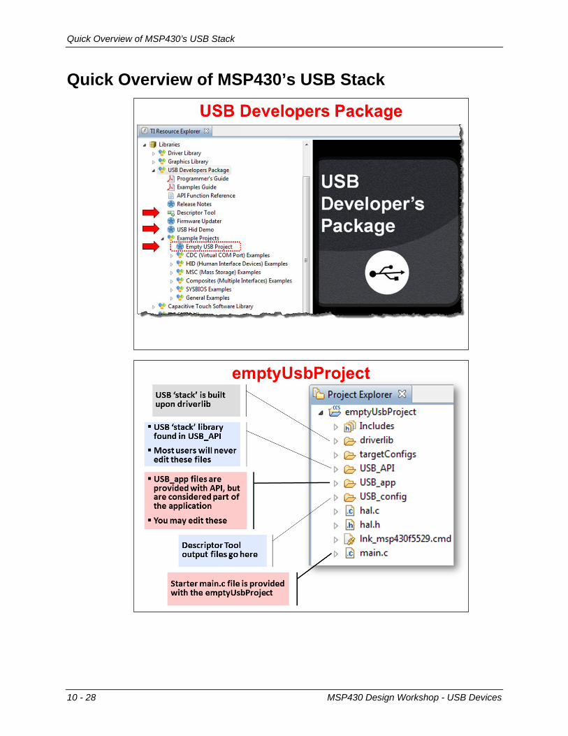
We bragged about the MSP430 development support. Here’s a peek at it. Looking at the items pointed out by the red arrows:
• We begin with the excellent USB Programmers Guide
• The Descriptor Tool is truly unique. It makes easy work of the tedious (and error prone) job of creating USB interface descriptors.
• The USB HID Demo is a Host-side tool that lets you interact with custom devices implementing the Human Interface Device class. It’s like a serial terminal program for HID devices.
• Finally, the rich set of examples provided by TI not only provides a way to “play” with USB, they also make excellent starting points for your own applications.
USB Developers Package
MSP430 Design Workshop - USB Devices 10 - 11
MSP430's USB Support
Sidebar – MSP430 USB API Features
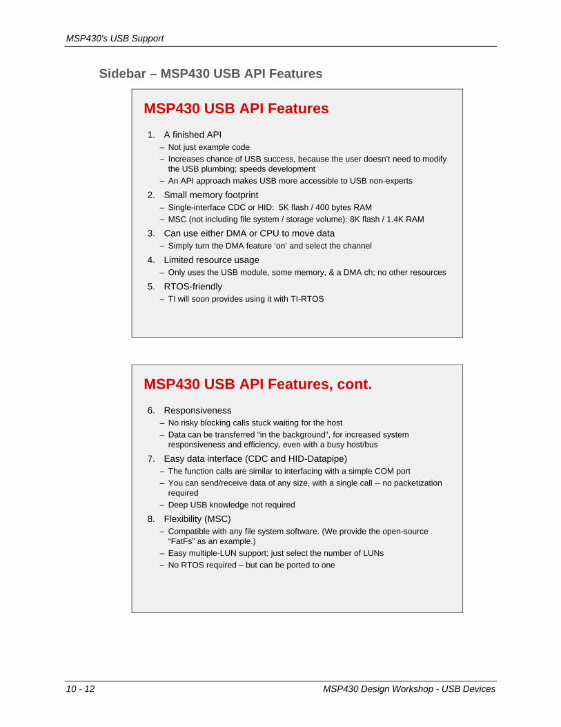
MSP430 USB API Features 1. A finished API
– Not just example code– Increases chance of USB success, because the user doesn’t need to modify
the USB plumbing; speeds development– An API approach makes USB more accessible to USB non-experts
2. Small memory footprint– Single-interface CDC or HID: 5K flash / 400 bytes RAM– MSC (not including file system / storage volume): 8K flash / 1.4K RAM
3. Can use either DMA or CPU to move data– Simply turn the DMA feature ‘on’ and select the channel
4. Limited resource usage– Only uses the USB module, some memory, & a DMA ch; no other resources
5. RTOS-friendly– TI will soon provides using it with TI-RTOS
MSP430 USB API Features, cont. 6. Responsiveness
– No risky blocking calls stuck waiting for the host– Data can be transferred “in the background”, for increased system
responsiveness and efficiency, even with a busy host/bus
7. Easy data interface (CDC and HID-Datapipe)– The function calls are similar to interfacing with a simple COM port– You can send/receive data of any size, with a single call -- no packetization
required– Deep USB knowledge not required
8. Flexibility (MSC)– Compatible with any file system software. (We provide the open-source
“FatFs” as an example.) – Easy multiple-LUN support; just select the number of LUNs– No RTOS required – but can be ported to one
10 - 12 MSP430 Design Workshop - USB Devices

MSP430's USB Support
USB Fees As we described earlier, your USB product needs a Vendor and Product ID (VID & PID) in order to meet the requirements of the standard. The USB Implementers Forum (USB-IF) charges a fee to license a Vendor ID.
As an alternative to purchasing your own VID, silicon vendors such as Texas Instruments, will provide you the ability to use their VID when using the MSP430 USB-based devices. Please refer to TI’s website for more information on obtaining a VID/PID.
MSP430 Design Workshop - USB Devices 10 - 13
MSP430's USB Support
Additional USB Resources Along with TI’s MSP430 USB page, we’ve provided some USB references that we found useful.
Suggested Reading
“Starting a USB Design Using aSt430™ aCUs” App Note by Keith Quiring (Sept 2013) (Search ti.com for SLAA457.pdf)
“trogrammers_Guide_aSt430_USB_AtI” by Texas Instruments (Aug 2013)Found in the aSt430 USB Developers tackage
“USB Complete: The Developer's Guide” by Jan Axelson (ISBN 1931448086)http://www.amazon.com/USB-Complete-Developers-Guide-Guides/dp/1931448086
10 - 14 MSP430 Design Workshop - USB Devices

How USB Works
How USB Works As we stated at the beginning of the chapter, USB is a serial, Master/Slave communication protocol. That is, the Host acts as the Master; communication to and from the Host is directed by the Host. The Device only responds to requests from the Host.
The USB standard allows many Devices to be connected to a single Host. The Host assigns an address to each Device as it is connected (i.e. enumerated) to the Host. This is really a minor detail, though, since – as a Device – we don’t need or use this information.
Logical Connection Between Host & Device
Device
Master
Slave
Communication takes place between the host and device
Host controls ALL communication Device is addressable
(assigned by host)
Host
MSP430 Design Workshop - USB Devices 10 - 15

How USB Works
Pipes and Endpoints To be more specific, a Host communicates with a Device through a Pipe; that is the name given to this communication pathway. The Pipe makes a connection to a Device Endpoint; which is essentially just a buffer in the Device. (As we’ll see in a minute, the MSP430 has dedicated Endpoints in its USB port hardware.)
Communication Pipes
Host
Device
Endpoint
Pipe
Host/Device communication occurs thru a Pipe
The host sets up pipe connections to one or more device “endpoints”
An endpoint is essentially a buffer in the device
10 - 16 MSP430 Design Workshop - USB Devices
How USB Works
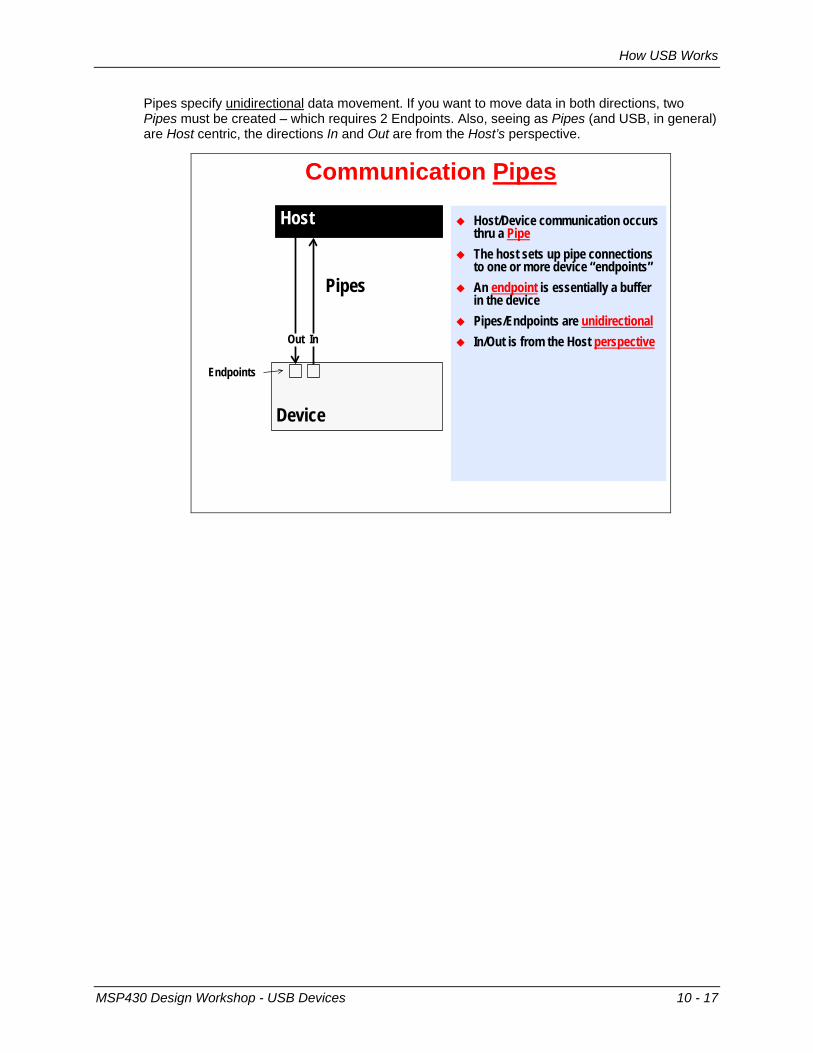
Pipes specify unidirectional data movement. If you want to move data in both directions, two Pipes must be created – which requires 2 Endpoints. Also, seeing as Pipes (and USB, in general) are Host centric, the directions In and Out are from the Host’s perspective.
Communication Pipes
Device
Pipes
InOut
Endpoints
Host/Device communication occurs thru a Pipe
The host sets up pipe connections to one or more device “endpoints”
An endpoint is essentially a buffer in the device
Pipes/Endpoints are unidirectional In/Out is from the Host perspective
Host
MSP430 Design Workshop - USB Devices 10 - 17
How USB Works
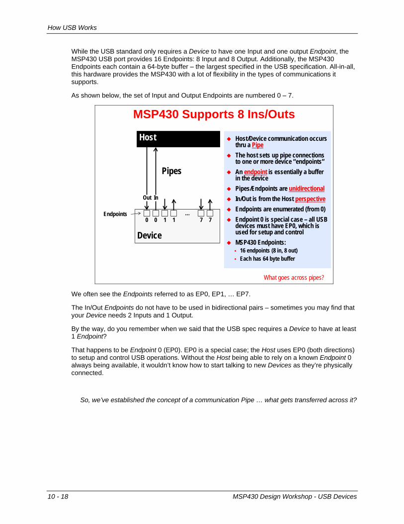
While the USB standard only requires a Device to have one Input and one output Endpoint, the MSP430 USB port provides 16 Endpoints: 8 Input and 8 Output. Additionally, the MSP430 Endpoints each contain a 64-byte buffer – the largest specified in the USB specification. All-in-all, this hardware provides the MSP430 with a lot of flexibility in the types of communications it supports.
As shown below, the set of Input and Output Endpoints are numbered 0 – 7.
MSP430 Supports 8 Ins/Outs
Device
Pipes
Host/Device communication occurs thru a Pipe
The host sets up pipe connections to one or more device “endpoints”
An endpoint is essentially a buffer in the device
Pipes/Endpoints are unidirectional In/Out is from the Host perspective Endpoints are enumerated (from 0) Endpoint 0 is special case – all USB
devices must have EP0, which is used for setup and control
MSP430 Endpoints: 16 endpoints (8 in, 8 out) Each has 64 byte buffer
00Endpoints …
11 77
Host
InOut
What goes across pipes?
We often see the Endpoints referred to as EP0, EP1, … EP7.
The In/Out Endpoints do not have to be used in bidirectional pairs – sometimes you may find that your Device needs 2 Inputs and 1 Output.
By the way, do you remember when we said that the USB spec requires a Device to have at least 1 Endpoint?
That happens to be Endpoint 0 (EP0). EP0 is a special case; the Host uses EP0 (both directions) to setup and control USB operations. Without the Host being able to rely on a known Endpoint 0 always being available, it wouldn’t know how to start talking to new Devices as they’re physically connected.
So, we’ve established the concept of a communication Pipe … what gets transferred across it?
10 - 18 MSP430 Design Workshop - USB Devices

How USB Works
USB Transfer Types Along with specifying an Endpoint and direction, a Pipe also specifies the “Type” of communication transfer. The USB specification supports four Transfer Types, as defined in this diagram.
USB Transfers
Device
Pipes
Pipe’s define a Transfer Type as well as the endpoint and direction
USB supports 4 Transfer Types: Control Setup/Command/Status Interrupt Small size, Periodic
Guaranteed latencyGuaranteed bandwidth
Bulk Large size allowedNo time guarantees
Isochronous Guar. time, PeriodicNo error handlingNot supported on ‘430
Contrary to the name, ‘interrupt’ transfers are not initiated by device
00Endpoints …
11 77
Host
InOut
How should we Frame this discussion?
If all we cared about was passing data across the Pipe, we wouldn’t need to further define the Transfer Type of a Pipe. The fact is, sometimes we care about “when” data will arrive, just as much as the data itself.
Each of the Transfer Types, listed above, briefly describe their temporal nature. Notice how “Interrupt” types provide a guaranteed latency and bandwidth, although the tradeoff is a smaller data payload. Conversely, “Bulk” transfers allow large sizes, but give up the time-oriented guarantees.
Hint: “Interrupt” transfer types do not have anything to do with microprocessor “interrupts”. It is just the word used in the USB specification to describe these types of transfers. Similarly, “Interrupt” transfer types are initiated by the Host, just as all USB transfers are initiated and controlled by the Host. (We’ll see more about this on the next page.)
Note: The MSP430 USB stack (i.e. USB library) only supports Control, Interrupt, and Bulk transfer types. Currently, the MSP430 does not support Isochronous types, which are more typically used in audio or video types of applications.
MSP430 Design Workshop - USB Devices 10 - 19
How USB Works
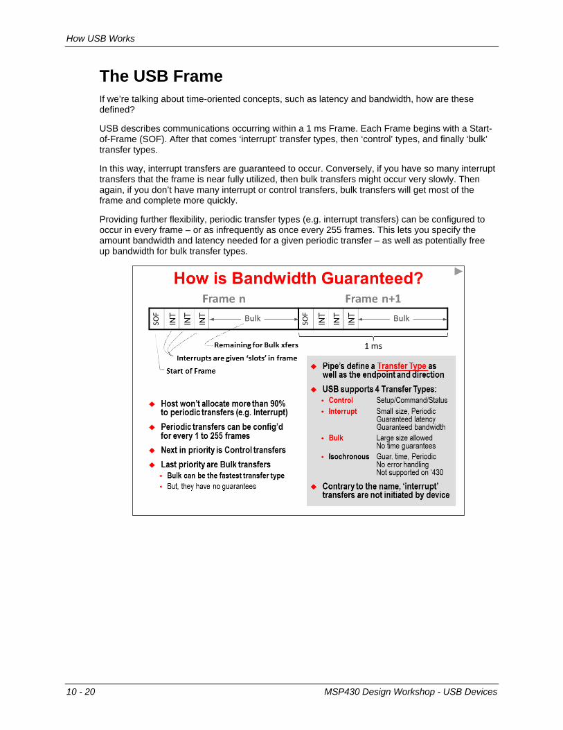
The USB Frame If we’re talking about time-oriented concepts, such as latency and bandwidth, how are these defined?
USB describes communications occurring within a 1 ms Frame. Each Frame begins with a Start-of-Frame (SOF). After that comes ‘interrupt’ transfer types, then ‘control’ types, and finally ‘bulk’ transfer types.
In this way, interrupt transfers are guaranteed to occur. Conversely, if you have so many interrupt transfers that the frame is near fully utilized, then bulk transfers might occur very slowly. Then again, if you don’t have many interrupt or control transfers, bulk transfers will get most of the frame and complete more quickly.
Providing further flexibility, periodic transfer types (e.g. interrupt transfers) can be configured to occur in every frame – or as infrequently as once every 255 frames. This lets you specify the amount bandwidth and latency needed for a given periodic transfer – as well as potentially free up bandwidth for bulk transfer types.
10 - 20 MSP430 Design Workshop - USB Devices
How USB Works
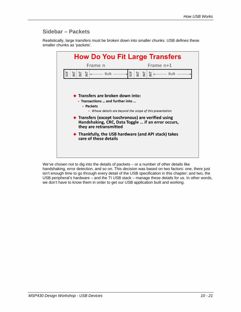
Sidebar – Packets Realistically, large transfers must be broken down into smaller chunks. USB defines these smaller chunks as ‘packets’.
We’ve chosen not to dig into the details of packets – or a number of other details like handshaking, error detection, and so on. This decision was based on two factors: one, there just isn’t enough time to go through every detail of the USB specification in this chapter; and two, the USB peripheral’s hardware – and the TI USB stack – manage these details for us. In other words, we don’t have to know them in order to get our USB application built and working.
MSP430 Design Workshop - USB Devices 10 - 21
Descriptions and Classes
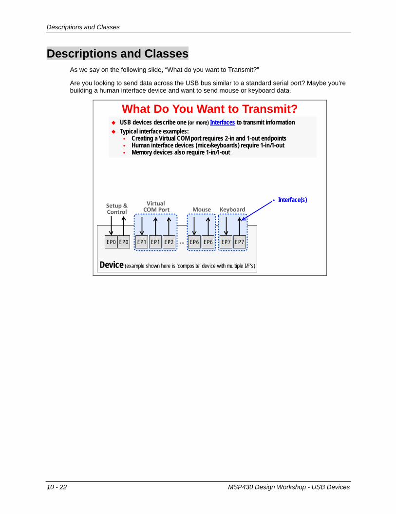
Descriptions and Classes As we say on the following slide, “What do you want to Transmit?”
Are you looking to send data across the USB bus similar to a standard serial port? Maybe you’re building a human interface device and want to send mouse or keyboard data.
Device (example shown here is ‘composite’ device with multiple I/F’s)
What Do You Want to Transmit? USB devices describe one (or more) Interfaces to transmit information Typical interface examples:
Creating a Virtual COM port requires 2-in and 1-out endpoints Human interface devices (mice/keyboards) require 1-in/1-out Memory devices also require 1-in/1-out
EP0 EP0 …EP1 EP1 EP7 EP7
Setup &Control
EP2
Virtual Cha tort
EP6 EP6
aouse Keyboard
Device DescriptorsConfiguration
Interface(s) Endpoint(s)
10 - 22 MSP430 Design Workshop - USB Devices

Descriptions and Classes
Device (example shown here is ‘composite’ device with multiple I/F’s)
Summary – USB Interface Description USB devices describe one (or more) Interfaces to transmit information Typical interface examples:
Creating a Virtual COM port requires 2-in and 1-out endpoints Human interface devices (mice/keyboards) require 1-in/1-out Memory devices also require 1-in/1-out
USB devices must describe their themselves using device descriptors Host must match descriptors (at run time) with host-side device drivers (INF) MSP430 supports a single configuration with
one or more interfaces
EP0 EP0 …EP1 EP1 EP7 EP7
Setup &Control
EP2
Virtual Cha tort
EP6 EP6
aouse Keyboard
Device Descriptors Configuration
Interface(s) Endpoint(s)
How can we simplify configuration?
MSP430 Design Workshop - USB Devices 10 - 23

Descriptions and Classes
USB Classes
Device
EP0 EP0 …EP1 EP1 EP7 EP7
Setup &Control
EP2
Virtual Cha tort
EP6 EP6
aouse Keyboard
USB defines a number of device classes: Human Interface Device (HID) Communications Device (CDC) Memory Storage Class (MSC)
MSP430 Supports 4 classes HID, CDC, MSC (and PHDC) Host O/S can easily match its
drivers to known device classes Simplifies specifying interfaces
(e.g. creating descriptors) Descriptors take form of:
Device: data-structures Host: .INF file
Is there an easy way to create USB Descriptors?
“CDC” “HID” “HID”
10 - 24 MSP430 Design Workshop - USB Devices
Descriptions and Classes
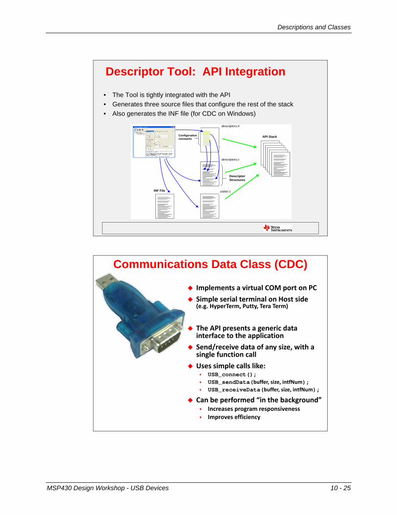
Descriptor Tool: API Integration
• The Tool is tightly integrated with the API• Generates three source files that configure the rest of the stack• Also generates the INF file (for CDC on Windows)
Configuration constants
descriptors.h
descriptors.c
usbisr.c
Descriptor Structures
API Stack
INF File
Communications Data Class (CDC)
Implements a virtual Cha port on tC Simple serial terminal on Host side
(e.g. HyperTerm, tutty, Tera Term)
The AtI presents a generic data interface to the application
Send/receive data of any size, with a single function call
Uses simple calls like: USB_connect(); USB_sendData(buffer, size, intfNum); USB_receiveData(buffer, size, intfNum);
Can be performed “in the background” Increases program responsiveness Improves efficiency
MSP430 Design Workshop - USB Devices 10 - 25
Descriptions and Classes
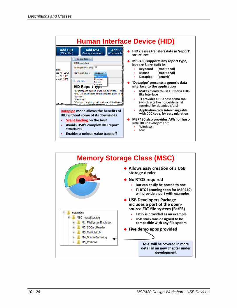
Human Interface Device (HID) HID classes transfers data in ‘report’
structures aSt430 supports any report type,
but are 3 are built-in: Keyboard (traditional) aouse (traditional) Datapipe (generic)
‘Datapipe’ presents a generic data interface to the application aakes it easy to use HID for a CDC-
like interface TI provides a HID host demo tool
(which acts like host-side serial terminal for datapipe xfers)
Application code interchangeable with CDC code, for easy migration
aSt430 also provides AtIs for host-side HID development: Windows Mac
Datapipe mode allows the benefits of HID without some of its downsides Silent loading on the host Avoids USB’s complex HID report
structures Enables a unique value tradeoff
Memory Storage Class (MSC) Allows easy creation of a USB
storage device No wThS required
But can easily be ported to one TI-wThS (coming soon for aSt430)
will provide a port with examples
USB Developers tackage includes a port of the open-source FAT file system (FatFS) FatFS is provided as an example USB stack was designed to be
compatible with any file system
Five demo apps provided
aSC will be covered in more detail in an new chapter under
development
10 - 26 MSP430 Design Workshop - USB Devices

Descriptions and Classes
Comparison/Summary of ClassesCDC HID MSCHost Interface Cha tort HID device Storage Volume
Host Loading User Intervention(user loads .inf file) Silent Silent
Bandwidth “Hundreds of KB/sec” 62KB/sec “Hundreds of KB/sec”
Code Size 5K 5K 9K(12-15K w/FS & vol)
Endpoints 2 in1 out
1 in1 out
1 in1 out
Transfer Type Bulk Interrupt Bulk (BhT)
Advantages Familiar to user Bulk transport Common host apps
Silent loading Interrupt xfers aouse/Keybd
Familiar to user Allows storage of
data using filesys
MSP430 Design Workshop - USB Devices 10 - 27
Quick Overview of MSP430’s USB Stack
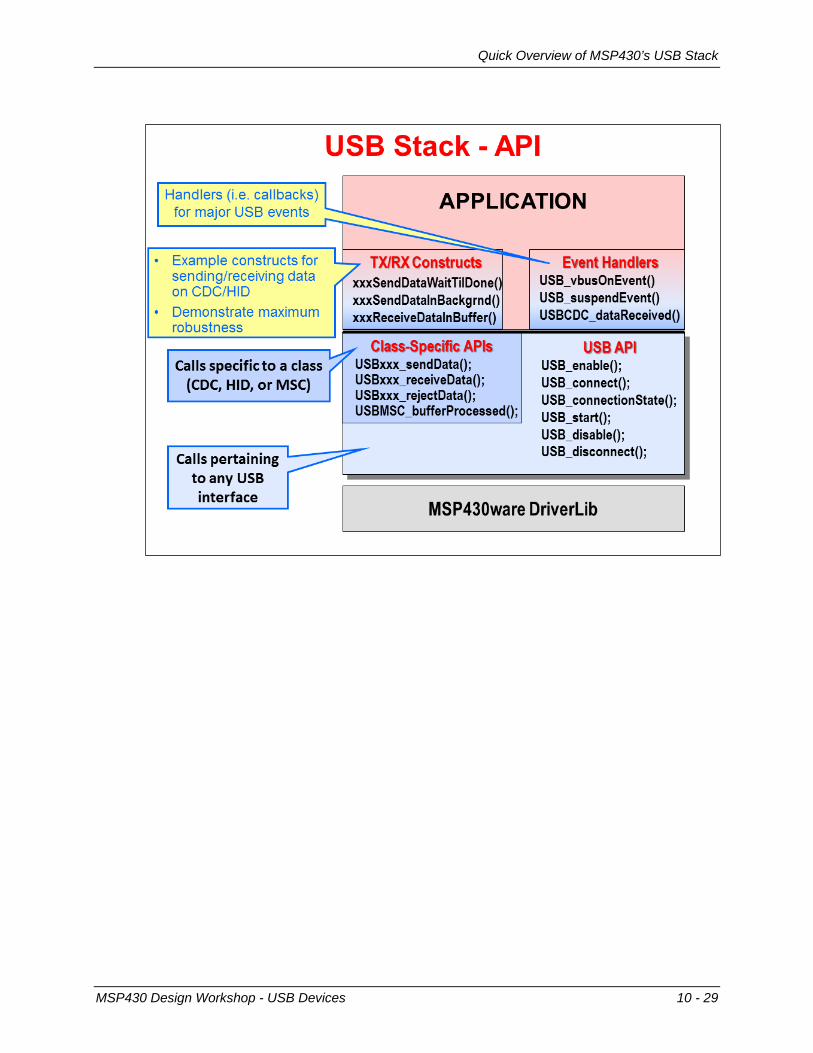
Quick Overview of MSP430’s USB Stack
10 - 28 MSP430 Design Workshop - USB Devices
Quick Overview of MSP430’s USB Stack
MSP430 Design Workshop - USB Devices 10 - 29

Notes:

ABC’s of USB
ABC’s of USB
A. Plan Your System
Plan Your System1. What are your requirements?
How much data needs to transfer … and how fast? Is guaranteed bandwidth & timing important? Are you connecting to Window, Mac, Linux (or all) What power will be needed?
2. From the requirements, decide which class (or classes) will be needed
3. Import EmptyUsbtroject (hptional) 4. wun Descriptor Tool
trovides help & feedback in creating device description Generates device descriptor files & INF files If you followed step 3, it automatically drops generated
files into the project
MSP430 Design Workshop - USB Devices 10 - 31
ABC’s of USB
B. Connect & Enumerate
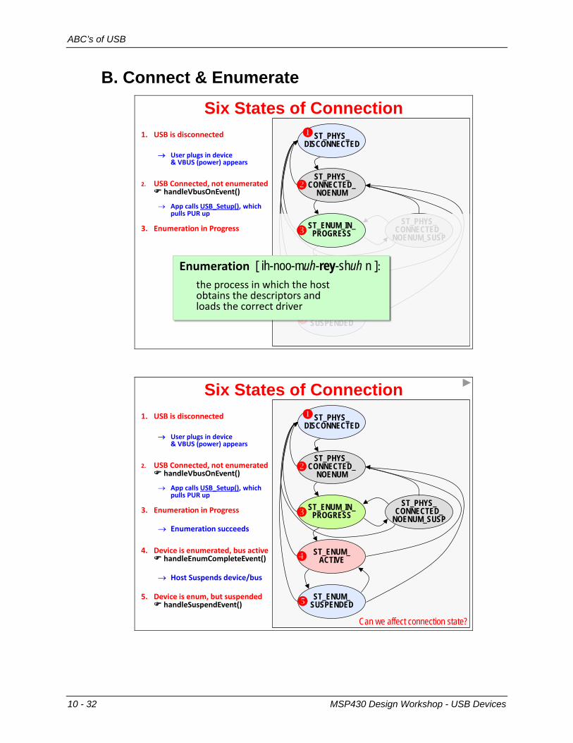
Six States of Connection1. USB is disconnected
→ User plugs in device & VBUS (power) appears
2. USB Connected, not enumerated handleVbushnEvent()
→ App calls USB_Setup(), which pulls tUw up
3. Enumeration in trogress
ST_PHYS_DISCONNECTED
ST_PHYS_CONNECTED_
NOENUM
ST_ENUM_ACTIVE
ST_ENUM_SUSPENDED
ST_PHYS_CONNECTED_
NOENUM_SUSP
x
ST_ENUM_IN_PROGRESSR
Enumerationthe process in which the host obtains the descriptors and loads the correct driver
[ ih-noo-muh-rey-shuh n ]:
Six States of Connection1. USB is disconnected
→ User plugs in device & VBUS (power) appears
2. USB Connected, not enumerated handleVbushnEvent()
→ App calls USB_Setup(), which pulls tUw up
3. Enumeration in trogress
→ Enumeration succeeds
4. Device is enumerated, bus active handleEnumCompleteEvent()
→ Host Suspends device/bus
5. Device is enum, but suspended handleSuspendEvent()
ST_PHYS_DISCONNECTED
ST_PHYS_CONNECTED_
NOENUM
ST_ENUM_IN_PROGRESS
ST_ENUM_ACTIVE
ST_ENUM_SUSPENDED
ST_PHYS_CONNECTED_
NOENUM_SUSP
R
x
Can we affect connection state?
10 - 32 MSP430 Design Workshop - USB Devices
ABC’s of USB
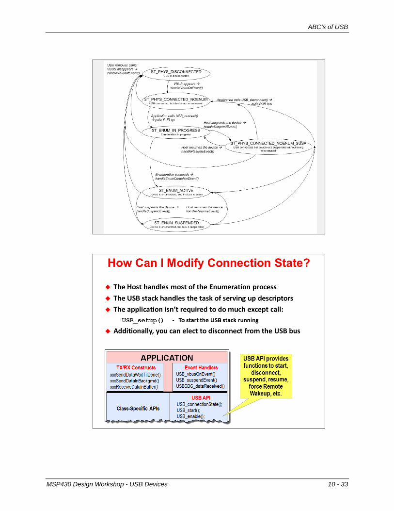
USB Connection States
MSP430 Design Workshop - USB Devices 10 - 33

ABC’s of USB
C. Managing my App & Transferring Data
Main Loop USB Frameworkwhile(1){
switch( USB_connectionState() ){
case ST_USB_DISCONNECTED:
break;case ST_ENUM_ACTIVE:
break;case ST_ENUM_SUSPENDED:
break;case ST_ENUM_IN_PROGRESS:
break;case ST_USB_CONNECTED_NO_ENUM:
break;case ST_NOENUM_SUSPENDED:
break;case ST_ERROR:
break;default:;
} }
Execution within main loop “forks” depending on the state of USB, creating alternate main loopsThus, USB state becomes a central part of managing software flow
This framework excels when the device behaves differently in each state!
For cases where system only cares about one state, connectionState() fxn could be called from IF{} stmt
aost common non-wThS solution –it’s used in many of the USB examples provided with the AtI
These three states are where the application spends most of its time
10 - 34 MSP430 Design Workshop - USB Devices
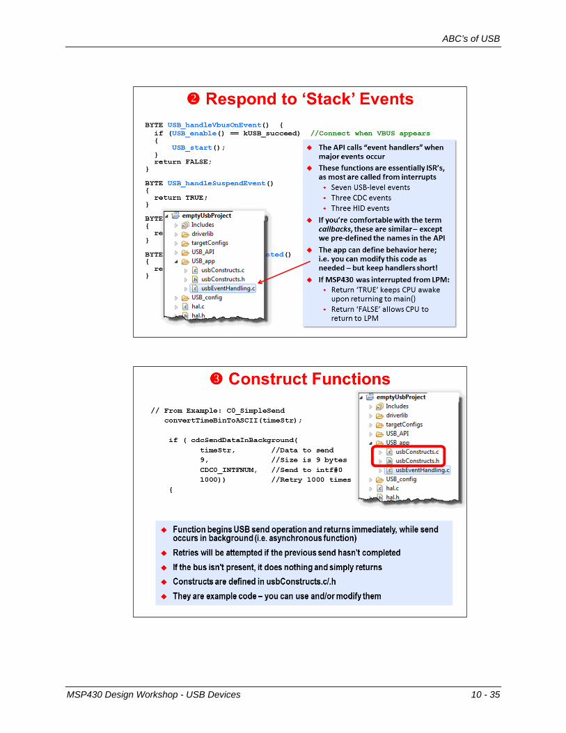
ABC’s of USB
MSP430 Design Workshop - USB Devices 10 - 35
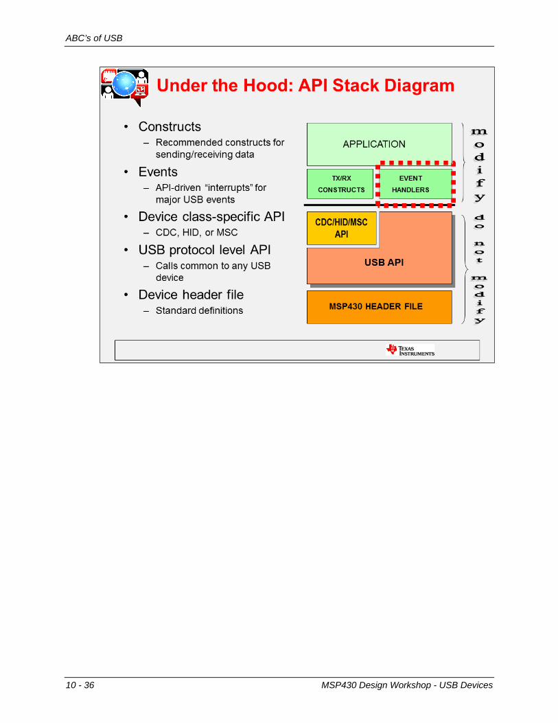
ABC’s of USB
10 - 36 MSP430 Design Workshop - USB Devices
Final Thoughts
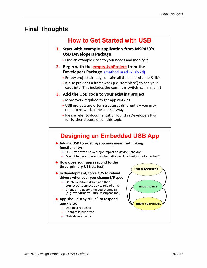
Final Thoughts
MSP430 Design Workshop - USB Devices 10 - 37
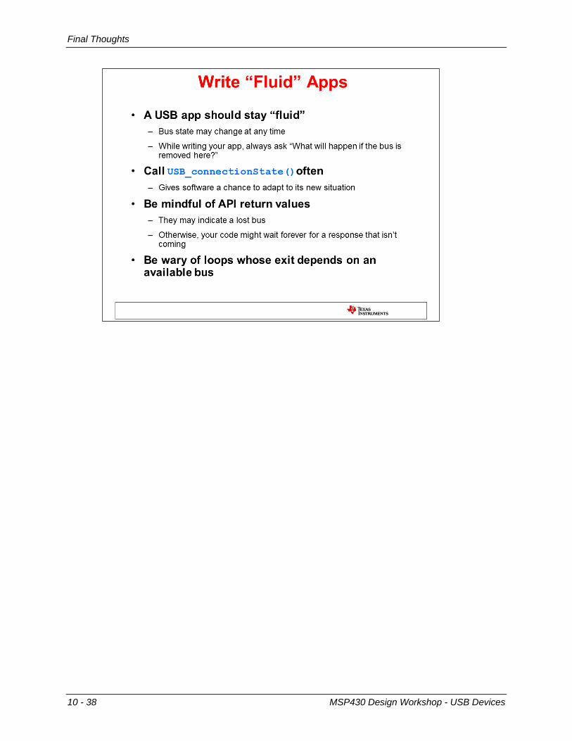
Final Thoughts
10 - 38 MSP430 Design Workshop - USB Devices
Lab 10 – Using USB Devices
Lab 10 – Using USB Devices
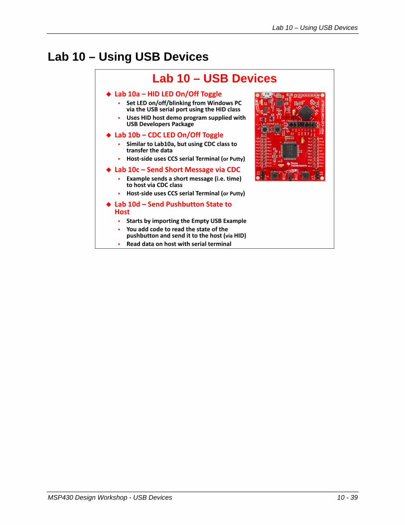
Lab 10 – USB Devices Lab 10a – HLD LED On/Off Toggle
Set LED on/off/blinking from Windows PC via the USB serial port using the HLD class
Uses HLD host demo program supplied with USB Developers Package
Lab 10b – CDC LED On/Off Toggle Similar to Lab10a, but using CDC class to
transfer the data Host-side uses CCS serial Terminal (or Putty)
Lab 10c – Send Short aessage via CDC Example sends a short message (i.e. time)
to host via CDC class Host-side uses CCS serial Terminal (or Putty)
Lab 10d – Send Pushbutton State to Host Starts by importing the Empty USB Example You add code to read the state of the
pushbutton and send it to the host (via HLD) Read data on host with serial terminal
MSP430 Design Workshop - USB Devices 10 - 39

Lab 10 – Using USB Devices
Lab Topics USB Devices ............................................................................................................................ 10-37
Lab 10 – Using USB Devices ................................................................................................ 10-39 Lab 10a – LED On/Off HID Example .................................................................................... 10-41 Lab 10b – LED On/Off CDC Example ................................................................................... 10-44
Play with the demo ............................................................................................................ 10-47 Lab 10c – CDC ‘Simple Send’ Example ............................................................................... 10-49 Lab 10d – Creating a CDC Push Button App ....................................................................... 10-51
Import Empty USB Project Steps ...................................................................................... 10-51 Use the Descriptor Tool .................................................................................................... 10-52 Add ‘Custom’ Code to Project ........................................................................................... 10-55
10 - 40 MSP430 Design Workshop - USB Devices

Lab 10a – LED On/Off HID Example
Lab 10a – LED On/Off HID Example The MSP430 USB Developers Package contains an example which changes the state of an LED based on string commands sent from the USB host.
1. Import the following example into your workspace using TI Resource Explorer.
Help → Welcome to CCS HID → Command-Line Interface with LED On/Off/Flash
2. Build the project.
3. Launch the debugger and wait for the program to load to flash; then start the program running.
At this point, the MSP430 should start running the USB application. You may see Windows enumerate the USB device (in this case, your Launchpad); this usually appears as a popup message from the system tray saying that a USB device (“USB input device”) was enumerated.
MSP430 Design Workshop - USB Devices 10 - 41

Lab 10a – LED On/Off HID Example
4. Open the USB HID Demo program.
TI provides a simple communications utility which can communicate with a USB device implementing the HID-datapipe class. Essentially, this utility allows us to communicate with devices much like a serial terminal lets us talk with CDC (comm port) devices.
When the program opens, it will look like this:
We’ll get back to this program in a minute. For now, return to CCS so that we can run the
demo code.
5. Switch back to the USB HID Demo application. With the USB program running on the Launchpad, let’s connect to it and send it commands.
6. Connect to the USB application.
Click the button that tells the HID app to find the USB device with the provided Vendor/Product IDs.
10 - 42 MSP430 Design Workshop - USB Devices
Lab 10a – LED On/Off HID Example
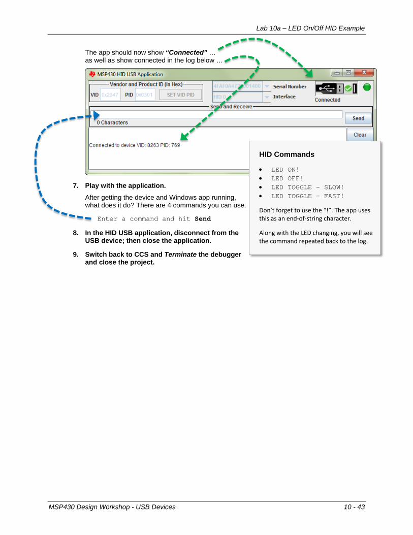
The app should now show “Connected” … as well as show connected in the log below …
7. Play with the application.
After getting the device and Windows app running, what does it do? There are 4 commands you can use.
Enter a command and hit Send
8. In the HID USB application, disconnect from the USB device; then close the application.
9. Switch back to CCS and Terminate the debugger and close the project.
HID Commands
• LED ON! • LED OFF! • LED TOGGLE – SLOW! • LED TOGGLE – FAST!
Don’t forget to use the “!”. The app uses this as an end-of-string character.
Along with the LED changing, you will see the command repeated back to the log.
MSP430 Design Workshop - USB Devices 10 - 43
Lab 10b – LED On/Off CDC Example
Lab 10b – LED On/Off CDC Example Our next program is another example from the MSP430 USB Developers Package. This program is a near duplicate of the previous lab – that is, it changes the state of an LED based on string commands sent from the USB host. In this example, though, the string commands are sent using the CDC class (versus the HID-datapipe class).
The advantage of the CDC class is that it can communicate with just about any Windows serial terminal application. The disadvantage, as you might remember from the discussion, is that Windows does not automatically load CDC based drivers – whereas Windows did this for us when using an HID class driver.
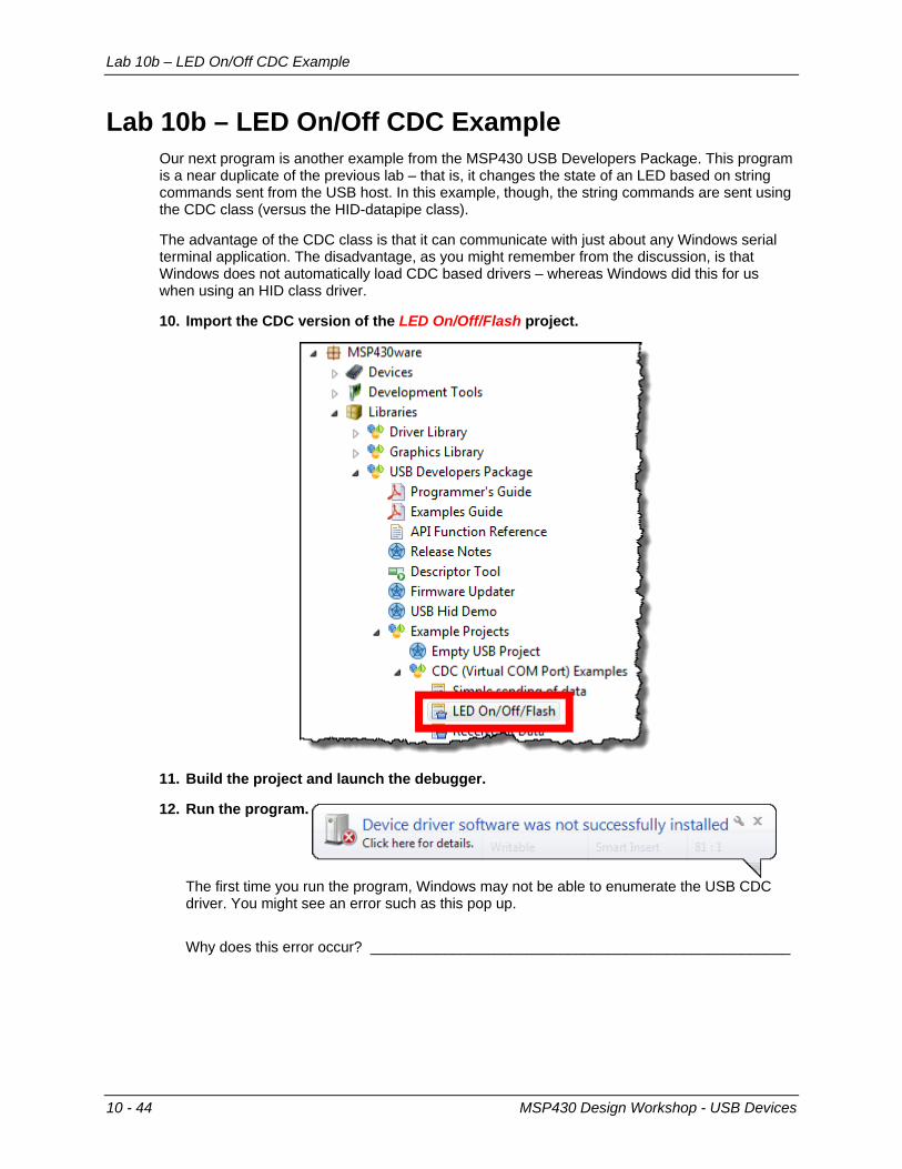
10. Import the CDC version of the LED On/Off/Flash project.
11. Build the project and launch the debugger.
12. Run the program.
The first time you run the program, Windows may not be able to enumerate the USB CDC driver. You might see an error such as this pop up.
Why does this error occur? ___________________________________________________
10 - 44 MSP430 Design Workshop - USB Devices

Lab 10b – LED On/Off CDC Example
13. Open the Windows Device Manager.
For Windows 7, the easiest way is to start the device manager is to type “Device” into the Start menu:
In most versions of Windows, such as Windows XP, you can also run the following program from a command line to start the Device Manager:
devmgmt.msc
On Windows XP, you can quickly run the command line from the Start Menu:
Start Menu → Run
You should find the a USB driver with a problem:
MSP430 Design Workshop - USB Devices 10 - 45
Lab 10b – LED On/Off CDC Example
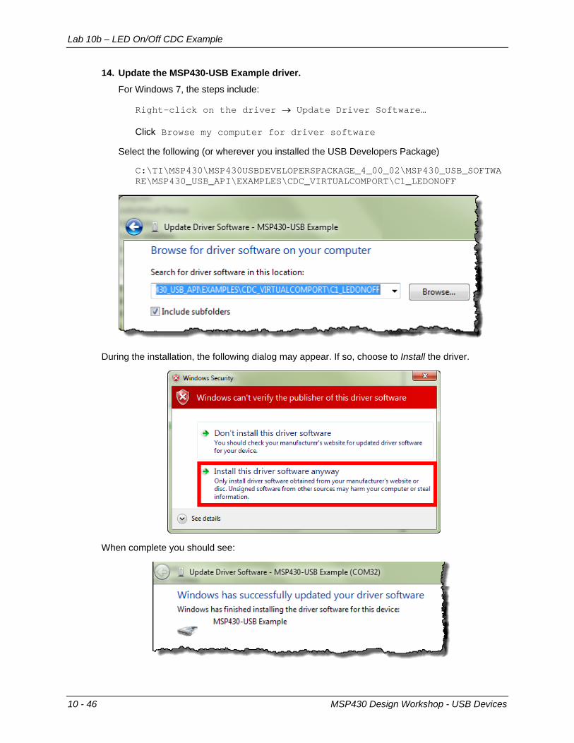
14. Update the MSP430-USB Example driver.
For Windows 7, the steps include:
Right-click on the driver → Update Driver Software… Click Browse my computer for driver software
Select the following (or wherever you installed the USB Developers Package)
C:\TI\MSP430\MSP430USBDEVELOPERSPACKAGE_4_00_02\MSP430_USB_SOFTWARE\MSP430_USB_API\EXAMPLES\CDC_VIRTUALCOMPORT\C1_LEDONOFF
During the installation, the following dialog may appear. If so, choose to Install the driver.
When complete you should see:
10 - 46 MSP430 Design Workshop - USB Devices
Lab 10b – LED On/Off CDC Example
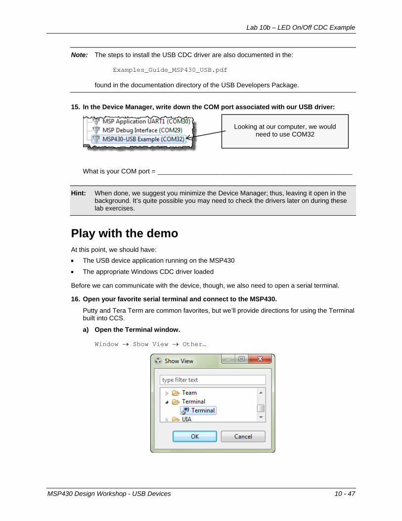
Note: The steps to install the USB CDC driver are also documented in the: Examples_Guide_MSP430_USB.pdf found in the documentation directory of the USB Developers Package.
15. In the Device Manager, write down the COM port associated with our USB driver:
What is your COM port = _____________________________________________________
Hint: When done, we suggest you minimize the Device Manager; thus, leaving it open in the background. It’s quite possible you may need to check the drivers later on during these lab exercises.
Play with the demo At this point, we should have: • The USB device application running on the MSP430
• The appropriate Windows CDC driver loaded
Before we can communicate with the device, though, we also need to open a serial terminal.
16. Open your favorite serial terminal and connect to the MSP430.
Putty and Tera Term are common favorites, but we’ll provide directions for using the Terminal built into CCS.
a) Open the Terminal window.
Window → Show View → Other…
Looking at our computer, we would need to use COM32
MSP430 Design Workshop - USB Devices 10 - 47
Lab 10b – LED On/Off CDC Example
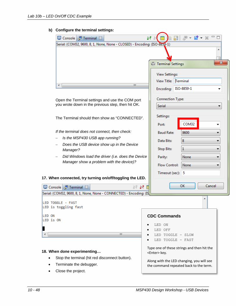
b) Configure the terminal settings:
Open the Terminal settings and use the COM port you wrote down in the previous step, then hit OK.
The Terminal should then show as “CONNECTED”.
If the terminal does not connect, then check: − Is the MSP430 USB app running?
− Does the USB device show up in the Device Manager?
− Did Windows load the driver (i.e. does the Device Manager show a problem with the device)?
17. When connected, try turning on/off/toggling the LED.
18. When done experimenting… • Stop the terminal (hit red disconnect button).
• Terminate the debugger.
• Close the project.
CDC Commands
• LED ON • LED OFF • LED TOGGLE – SLOW • LED TOGGLE – FAST
Type one of these strings and then hit the <Enter> key.
Along with the LED changing, you will see the command repeated back to the term.
10 - 48 MSP430 Design Workshop - USB Devices

Lab 10c – CDC ‘Simple Send’ Example
Lab 10c – CDC ‘Simple Send’ Example Let’s try one more simple application example before we build our own. This next example simply sends the time (from MSP430’s Real Time Clock) to a serial terminal.
19. Similar to our previous two examples, import the “Simple Sending of Data” project.
20. Build the project and launch the debugger.
21. Start the program.
22. Wait for the USB device to enumerate.
If you’re not sure that Windows enumerated the device, check the Device Manager. If it does not enumerate, try Terminating the debugger, unplugging the Launchpad, then plugging it back into another USB port on your computer.
23. Once enumerated, start the Terminal again (by hitting the Green Connection button). You should see the time printed (repeatedly) to the Terminal.
MSP430 Design Workshop - USB Devices 10 - 49
Lab 10c – CDC ‘Simple Send’ Example
24. Once you are done watch time go by: disconnect the Terminal; Terminate the debugger (if you didn’t do it in the last step).
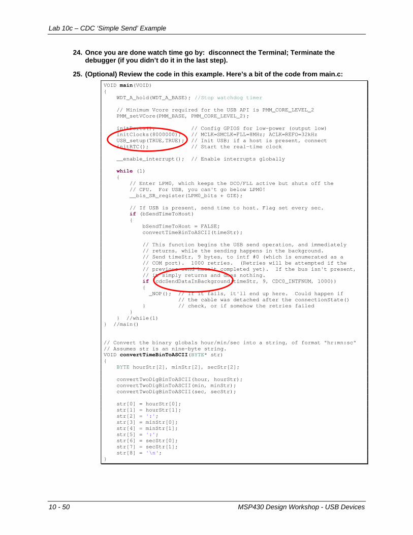
25. (Optional) Review the code in this example. Here’s a bit of the code from main.c: VOID main(VOID) { WDT_A_hold(WDT_A_BASE); //Stop watchdog timer // Minimum Vcore required for the USB API is PMM_CORE_LEVEL_2 PMM_setVCore(PMM_BASE, PMM_CORE_LEVEL_2); initPorts(); // Config GPIOS for low-power (output low) initClocks(8000000); // MCLK=SMCLK=FLL=8MHz; ACLK=REFO=32kHz USB_setup(TRUE,TRUE); // Init USB; if a host is present, connect initRTC(); // Start the real-time clock __enable_interrupt(); // Enable interrupts globally while (1) { // Enter LPM0, which keeps the DCO/FLL active but shuts off the // CPU. For USB, you can't go below LPM0! __bis_SR_register(LPM0_bits + GIE); // If USB is present, send time to host. Flag set every sec. if (bSendTimeToHost) { bSendTimeToHost = FALSE; convertTimeBinToASCII(timeStr); // This function begins the USB send operation, and immediately // returns, while the sending happens in the background. // Send timeStr, 9 bytes, to intf #0 (which is enumerated as a // COM port). 1000 retries. (Retries will be attempted if the // previous send hasn't completed yet). If the bus isn't present, // it simply returns and does nothing. if (cdcSendDataInBackground(timeStr, 9, CDC0_INTFNUM, 1000)) { _NOP(); // If it fails, it'll end up here. Could happen if // the cable was detached after the connectionState() } // check, or if somehow the retries failed } } //while(1) } //main() // Convert the binary globals hour/min/sec into a string, of format "hr:mn:sc" // Assumes str is an nine-byte string. VOID convertTimeBinToASCII(BYTE* str) { BYTE hourStr[2], minStr[2], secStr[2]; convertTwoDigBinToASCII(hour, hourStr); convertTwoDigBinToASCII(min, minStr); convertTwoDigBinToASCII(sec, secStr); str[0] = hourStr[0]; str[1] = hourStr[1]; str[2] = ':'; str[3] = minStr[0]; str[4] = minStr[1]; str[5] = ':'; str[6] = secStr[0]; str[7] = secStr[1]; str[8] = '\n'; }
10 - 50 MSP430 Design Workshop - USB Devices
Lab 10d – Creating a CDC Push Button App
Lab 10d – Creating a CDC Push Button App We have experimented with three example USB applications. It’s finally time to build one from “scratch”. Well, not really from scratch, since we can start with the “Empty USB Example”.
The goal of our application is to send the state of the Launchpad button to the PC via USB – using the HID Datapipe interface. Thus, we’ll use a HID class driver. This application will borrow from a number of programs we’ve already written:
GPIO – We will read the push button and light the LED when it is pushed. Also, we’ll send “DOWN” when it’s down and “UP” when it’s up.
Timer – We’ll use a timer to generate an interrupt every second. In the Timer ISR we’ll set a flag. When the flag is TRUE, we’ll read the button and send the proper string to the host.
HID Simple Send Example – we’ll borrow a bit of code from the HID example we just ran to ‘package’ up our string and send it via USB to the host.
Finally, we’re going to start by following the first 3 steps provided in TI Resource Explorer for the Empty USB Example.
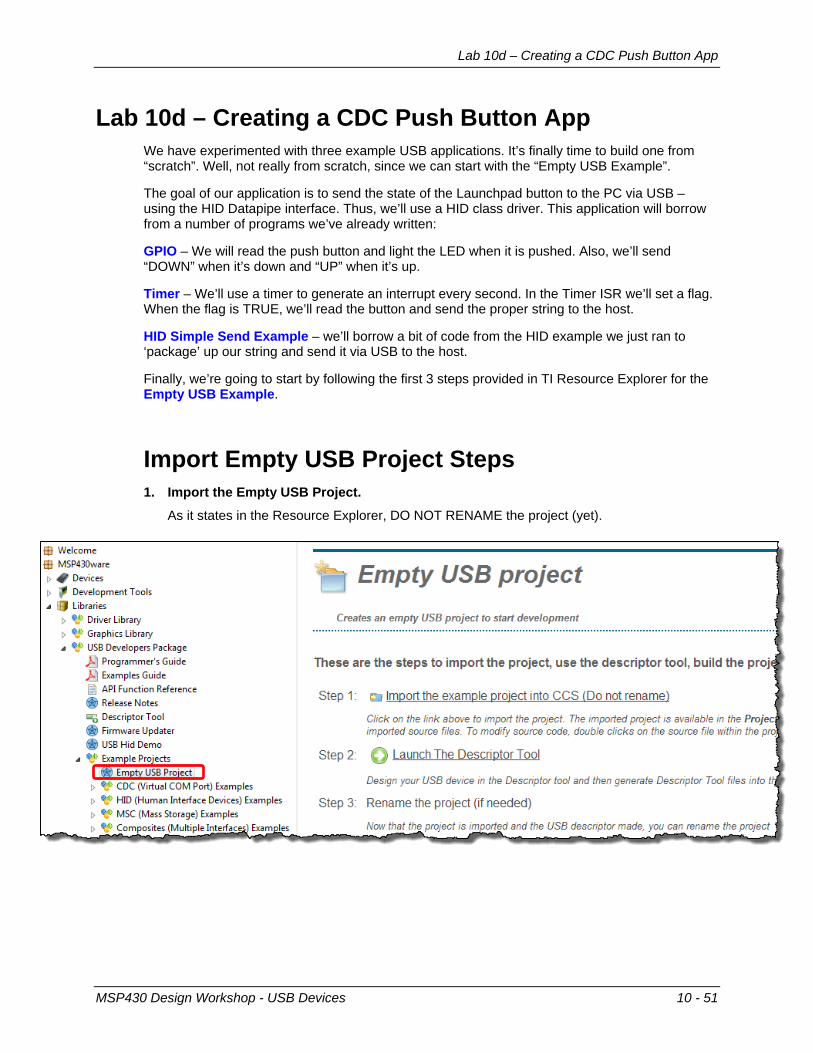
Import Empty USB Project Steps 1. Import the Empty USB Project.
As it states in the Resource Explorer, DO NOT RENAME the project (yet).
MSP430 Design Workshop - USB Devices 10 - 51

Lab 10d – Creating a CDC Push Button App
Use the Descriptor Tool 2. Launch the Descriptor Tool.
Just as the Resource Explorer directs us, launch the Descriptor Tool. The easiest way to do this is to click the link as shown above.
3. Generate descriptor files using the Descriptor Tool.
We will take a quick look at the organization levels in the tool. In most cases, we will use the tools defaults.
a) MSP430 level … use the defaults.
b) USB Device … MSP430-Button Example
We suggest changing the Product String – so it’ll be easier to see that it is different than previous examples. Also, we suggest changing the PID (we picked ‘301’ arbitrarily). For a real design, you might end up purchasing the VID/PID (or obtain a free PID from TI).
10 - 52 MSP430 Design Workshop - USB Devices
Lab 10d – Creating a CDC Push Button App
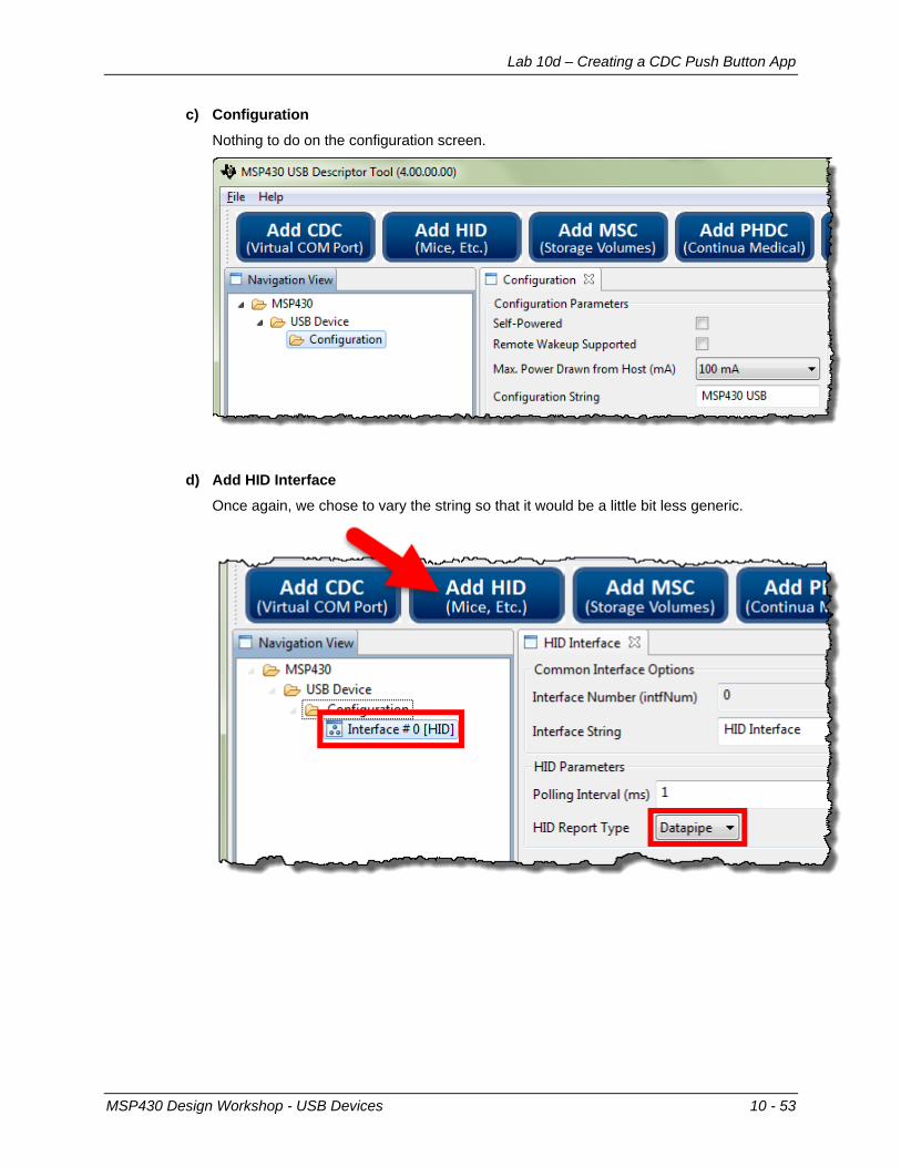
c) Configuration
Nothing to do on the configuration screen.
d) Add HID Interface Once again, we chose to vary the string so that it would be a little bit less generic.
MSP430 Design Workshop - USB Devices 10 - 53
Lab 10d – Creating a CDC Push Button App
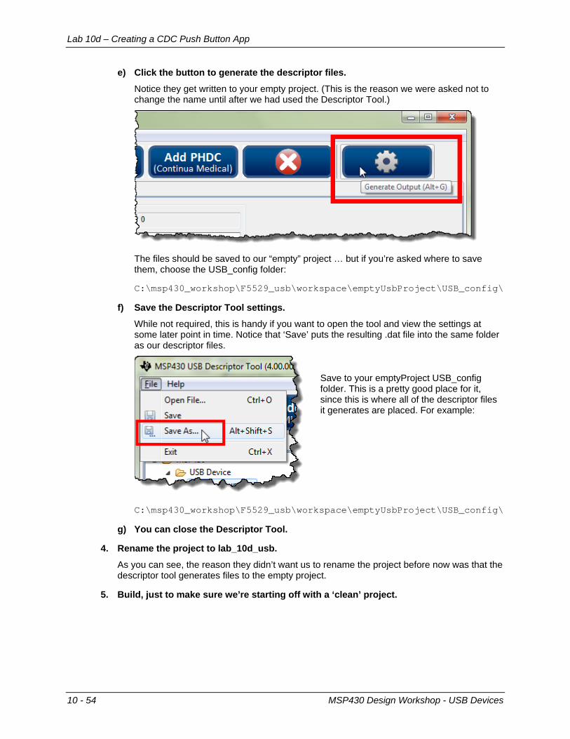
e) Click the button to generate the descriptor files.
Notice they get written to your empty project. (This is the reason we were asked not to change the name until after we had used the Descriptor Tool.)
The files should be saved to our “empty” project … but if you’re asked where to save them, choose the USB_config folder:
C:\msp430_workshop\F5529_usb\workspace\emptyUsbProject\USB_config\
f) Save the Descriptor Tool settings.
While not required, this is handy if you want to open the tool and view the settings at some later point in time. Notice that ‘Save’ puts the resulting .dat file into the same folder as our descriptor files.
Save to your emptyProject USB_config folder. This is a pretty good place for it, since this is where all of the descriptor files it generates are placed. For example:
C:\msp430_workshop\F5529_usb\workspace\emptyUsbProject\USB_config\
g) You can close the Descriptor Tool.
4. Rename the project to lab_10d_usb.
As you can see, the reason they didn’t want us to rename the project before now was that the descriptor tool generates files to the empty project.
5. Build, just to make sure we’re starting off with a ‘clean’ project.
10 - 54 MSP430 Design Workshop - USB Devices
Lab 10d – Creating a CDC Push Button App
Add ‘Custom’ Code to Project 6. Copy myTimer.c and myTimer.h (and the readme file) to the project folder.
We’ve already written the timer routine for you. (Look back to our Timer chapter if you want to know the details of how this code was developed.)
Right-click the project → Add Files…
Choose the three files from the location:
C:\msp430_workshop\F5529_usb\lab_10d_usb\
7. Open main.c and add a #include for the myTimer.h.
We suggest doing this somewhere below #include “driverlib.h”.
8. Add global variables.
These are used to capture (and send) the button up/down state. char pbStr[5] = ""; // Stores the string to send volatile unsigned short usiButton1 = 0; // Stores the button state
9. Add additional setup code. We need to initialize an LED and pushbutton. We also need to call the initTimers() function
that was just added to our project in a previous step. GPIO_setAsOutputPin( GPIO_PORT_P4, GPIO_PIN7 ); GPIO_setAsInputPinWithPullUpresistor( GPIO_PORT_P2, GPIO_PIN1 ); initTimers();
10. Modify the low-power state of the program. Search down toward the end of main() until you find the intrinsic that sets the program into
low-power mode. Rather than using LPM3, we want to switch this to LPM0. // _bis_SR_register(LPM3_bits + GIE); __bis_SR_register(LPM0_bits + GIE);
MSP430 Design Workshop - USB Devices 10 - 55

Notes:
Lab 10d – Creating a CDC Push Button App
11. Add code to ST_ENUM_ACTIVE state.
The active state is where we want to put our communication code. (It only makes sense to that we send data to the host when we’re actively connected.
When connected, we will read the pin, set the Launchpad’s LED and then construct a string to send to the host. Finally, we send the data to the host in the background; that is, we won’t wait for a response – although we do set a timeout in our code below.
Note that it’s the timer that wakes us up every second to check the state – and if the USB is in the connected state, to run through the routine below.
// If USB is present, sent the button state to host. Flag set every sec if (bSend) { bSend = FALSE; usiButton1 = GPIO_getInputPinValue ( GPIO_PORT_P2, GPIO_PIN1 ); if ( usiButton1 == GPIO_INPUT_PIN_LOW ) { // If button is down, turn on LED GPIO_setOutputHighOnPin( GPIO_PORT_P4, GPIO_PIN7 ); pbStr[0] = 'D'; pbStr[1] = 'O'; pbStr[2] = 'W'; pbStr[3] = 'N'; pbStr[4] = '\n'; } else { // If button is up, turn off LED GPIO_setOutputLowOnPin( GPIO_PORT_P4, GPIO_PIN7 ); pbStr[0] = 'U'; pbStr[1] = 'P'; pbStr[2] = ' '; pbStr[3] = ' '; pbStr[4] = '\n'; } // This function begins the USB send operation, and immediately // returns, while the sending happens in the background. // Send pbStr, 5 bytes, to intf #0 (which is enumerated as a // HID port). 1000 retries. (Retries will be attempted if the // previous send hasn't completed yet). If the bus isn't present, // it simply returns and does nothing. if (cdcSendDataInBackground((BYTE*)pbStr, 5, HID0_INTFNUM, 1000)) { _NOP(); // If it fails, it'll end up here. Could happen if // the cable was detached after the connectionState() } // check, or if somehow the retries failed }
12. Add #include "USB_app/usbConstructs.h".
We need to use this header file since it supports the hidSendDataInBackground() function we are using to send data via USB.
13. Build the program and launch debugger.
MSP430 Design Workshop - USB Devices 10 - 57
Lab 10d – Creating a CDC Push Button App
14. Start your program and open the USB HID demo tool.
You can either run the program from within the debugger – or – terminate the debugger and unplug and then plug the Launchpad back in. In either case, your USB program should be running.
We need to use the HID tool to view the communications coming from the Launchpad. As we mentioned earlier, it acts as a “terminal” for our HID Datapipe datastream.
If you cannot remember how to open it, please refer back to Step 4 on page 10-42.
Hint: You might have to set the PID depending upon the value you selected while using the Descriptor tool.
15. Verify your program works
Once the the driver is loaded and working properly, open your Terminal, making sure to use the proper comm port. (As a reminder, all of these steps we discussed earlier in this chapter.)
At this point: • The Red LED should be blinking on/off.
• The Green LED should light when Button1 is pushed …
• … and the state of the button should be written to the HID Terminal.
Remember that the code only tests the button once per second. So, you will need to hold (or release) it for more than a second for it to take effect.
10 - 58 MSP430 Design Workshop - USB Devices