usb-cascading user guide - raritan...
TRANSCRIPT
USB-Cascading Solution
Guide Release 3.2.10
Copyright © 2016 Raritan, Inc.
USBcascade-0E-v3.2.10-E
March 2016
255-80-0012-00 RoHS

Safety Guidelines
WARNING! Read and understand all sections in this guide before installing or operating this product.
WARNING! Connect this product to an AC power source whose voltage is within the range specified on the product's nameplate. Operating this product outside the nameplate voltage range may result in electric shock, fire, personal injury and death.
WARNING! Connect this product to an AC power source that is current limited by a suitably rated fuse or circuit breaker in accordance with national and local electrical codes. Operating this product without proper current limiting may result in electric shock, fire, personal injury and death.
WARNING! Connect this product to a protective earth ground. Never use a "ground lift adaptor" between the product's plug and the wall receptacle. Failure to connect to a protective earth ground may result in electric shock, fire, personal injury and death.
WARNING! This product contains no user serviceable parts. Do not open, alter or disassemble this product. All servicing must be performed by qualified personnel. Disconnect power before servicing this product. Failure to comply with this warning may result in electric shock, personal injury and death.
WARNING! Use this product in a dry location. Failure to use this product in a dry location may result in electric shock, personal injury and death.
WARNING! Do not rely on this product's receptacle lamps, receptacle relay switches or any other receptacle power on/off indicator to determine whether power is being supplied to a receptacle. Unplug a device connected to this product before performing repair, maintenance or service on the device. Failure to unplug a device before servicing it may result in electric shock, fire, personal injury and death.
WARNING! Only use this product to power information technology equipment that has a UL/IEC 60950-1 or equivalent rating. Attempting to power non-rated devices may result in electric shock, fire, personal injury and death.
WARNING! Do not use a Raritan product containing outlet relays to power large inductive loads such as motors or compressors. Attempting to power a large inductive load may result in damage to the relay.
WARNING! Do not use this product to power critical patient care equipment, fire or smoke alarm systems. Use of this product to power such equipment may result in personal injury and death.
WARNING! If this product is a model that requires assembly of its line cord or plug, all such assembly must be performed by a licensed electrician and the line cord or plugs used must be suitably rated based on the product's nameplate ratings and national and local electrical codes. Assembly by unlicensed electricians or failure to use suitably rated line cords or plugs may result in electric shock, fire, personal injury or death.
WARNING! This product contains a chemical known to the State of California to cause cancer, birth defects, or other reproductive harm.
Safety Instructions
1. Installation of this product should only be performed by a person who has knowledge and experience with electric power.
2. Make sure the line cord is disconnected from power before physically mounting or moving the location of this product.
3. This product is designed to be used within an electronic equipment rack. The metal case of this product is electrically bonded to the line cord ground wire. A threaded grounding point on the case may be used as an additional means of protectively grounding this product and the rack.
4. Examine the branch circuit receptacle that will supply electric power to this product. Make sure the receptacle’s power lines, neutral and protective earth ground pins are wired correctly and are the correct voltage and phase. Make sure the branch circuit receptacle is protected by a suitably rated fuse or circuit breaker.
5. If the product is a model that contains receptacles that can be switched on/off, electric power may still be present at a receptacle even when it is switched off.

This document contains proprietary information that is protected by copyright. All rights reserved. No part of this document may be photocopied, reproduced, or translated into another language without express prior written consent of Raritan, Inc.
© Copyright 2016 Raritan, Inc. All third-party software and hardware mentioned in this document are registered trademarks or trademarks of and are the property of their respective holders.
FCC Information
This equipment has been tested and found to comply with the limits for a Class A digital device, pursuant to Part 15 of the FCC Rules. These limits are designed to provide reasonable protection against harmful interference in a commercial installation. This equipment generates, uses, and can radiate radio frequency energy and if not installed and used in accordance with the instructions, may cause harmful interference to radio communications. Operation of this equipment in a residential environment may cause harmful interference.
VCCI Information (Japan)
Raritan is not responsible for damage to this product resulting from accident, disaster, misuse, abuse, non-Raritan modification of the product, or other events outside of Raritan's reasonable control or not arising under normal operating conditions.
If a power cable is included with this product, it must be used exclusively for this product.
vi
Contents
Safety Guidelines ii
Safety Instructions iii
What's New in the USB-Cascading Solution Guide ix
Chapter 1 Introduction 1
Hardware Requirements................................................................................................................1 Software Requirements .................................................................................................................2 Overview of the Cascading Modes ................................................................................................3 Plug and Play.................................................................................................................................4
Chapter 2 USB-Cascading Applications 5
Appropriate Applications................................................................................................................5 Best Practices ................................................................................................................................7 Inappropriate Applications .............................................................................................................7
Chapter 3 USB-Cascading Instructions 8
USB-Cascading Restrictions .........................................................................................................8 Cascading the Raritan Devices via USB .......................................................................................9 Setting the Cascading Mode........................................................................................................11
Port Number Syntax ..........................................................................................................13 Port Forwarding Examples ................................................................................................14
Chapter 4 Network Access 17
Finding the IP Address ................................................................................................................17 Local Console ....................................................................................................................17 MAC Address.....................................................................................................................18 LCD Display.......................................................................................................................18
Contents
vii
HTTP/HTTPS Access ..................................................................................................................22 Supported Web Browsers..................................................................................................23 Using the Web Browser.....................................................................................................23
SSH/Telnet Access......................................................................................................................25 SNMP Management.....................................................................................................................26
SNMP Notifications............................................................................................................26 Third-Party SNMP Managers ............................................................................................26
Chapter 5 Identifying Cascaded Devices 27
Using the Web Interface ..............................................................................................................27 Using the CLI ...............................................................................................................................34 Using the SNMP ..........................................................................................................................36 Using the LCD Display.................................................................................................................38
Dot-Matrix LCD Display .....................................................................................................38 Character LCD Display......................................................................................................40
Chapter 6 Updating the Raritan Device Firmware 42
Appendix A Configuring Network Settings 44
Configuration via Web Interface ..................................................................................................44 Configuration via CLI ...................................................................................................................45
Appendix B Accessibility Troubleshooting 51
Possible Root Causes .................................................................................................................51 Slave Connection and Disconnection Events..............................................................................52 The Ping Tool...............................................................................................................................52
Using the Web Interface ....................................................................................................52 Using the CLI .....................................................................................................................53
Contents
viii
Appendix C Ethernet Disabled Scenarios on Slave Devices 55
Example 1 ....................................................................................................................................55 Example 2 ....................................................................................................................................56
Appendix D Wireless LAN Information 57
Supported Wireless LAN Configuration.......................................................................................57 USB Wireless LAN Adapters .......................................................................................................57
Index 59
ix
The following sections have changed or information has been added to the USB-Cascading Solution Guide based on changes and enhancements to the Raritan software and/or user documentation.
Software Requirements (on page 2)
Overview of the Cascading Modes (on page 3)
Network Access (on page 17)
Supported Web Browsers (on page 23)
What's New in the USB-Cascading Solution Guide
Introduction Chapter 1
Raritan provides a USB-cascading solution, which enables multiple Raritan devices to share the network connectivity after cascading them through the USB interface.
The first device in the USB-cascading configuration is the master device and the other are slave devices.
Each individual device in the USB-cascading configuration can be accessed and administered over the Internet from anywhere. Therefore, you can access any device in the chain via the Web, SNMP, SSH, Telnet or Modbus interface. Besides, each cascaded device can be upgraded respectively.
In This Chapter
Hardware Requirements............................................................................1 Software Requirements .............................................................................2 Overview of the Cascading Modes............................................................3 Plug and Play ............................................................................................4
Hardware Requirements
Raritan products supporting the USB-cascading feature:
PX2 series power distribution units (PDUs)
PX3 series PDUs
EMX asset management devices
Branch Circuit Monitor (BCM)
PX3TS transfer switch
The USB-cascading configuration comprises either identical or diverse Raritan products. For example, you can cascade PX2 PDUs only, or you can cascade PX2, PX3, EMX, PX3TS and BCM devices in the USB-cascading configuration.
If wireless networking is intended:
A Raritan product with two USB-A ports must be the master device, such as PX3 or PX3TS. Slave devices can be any Raritan products shown in the above list. See Cascading the Raritan Devices via USB (on page 9) for information on master and slave devices.
1
Chapter 1: Introduction
2
Software Requirements
A Raritan device must run an appropriate firmware to support the USB-cascading feature.
Depending on the firmware version implemented, the maximum number of cascaded devices that are supported in a USB-cascading configuration differs.
Firmware versions supporting a maximum of four Raritan devices:
PX2 series: 2.3.1 or later
PX3 series: 2.5.10 or later
EMX series: 2.2.0 or later
BCM series: 2.3.1 or later
Firmware versions supporting a maximum of eight Raritan devices:
PX2 series: 2.5.20 or later
PX3 series: 2.5.20 or later
EMX series: 2.5.0 or later
BCM series: 2.5.20 or later
PX3TS series: 2.6.0 or later
Firmware versions supporting different cascading and networking modes:
Cascading modes:
The firmware versions supporting four devices support the "Bridging" cascading mode only.
The firmware versions supporting eight devices support both "Bridging" and "Port Forwarding" cascading modes.
If the "Port Forwarding" mode is intended, you must upgrade all devices in the chain to support two cascading modes. See Overview of the Cascading Modes (on page 3).
Chapter 1: Introduction
3
Networking modes:
The USB-cascading configuration only supports the wired network prior to release 3.1.0.
As of release 3.1.0, the USB-cascading configuration supports both wired and "wireless" networks. See Overview of the Cascading Modes (on page 3).
Upgrade all devices in the chain to version 3.1.0 or later when wireless networking is intended.
Note: A Raritan product with two USB-A ports must be the master device, such as PX3 or PX3TS.
Check firmware versions before cascading Raritan devices and upgrade any device as needed. See Updating the Raritan Device Firmware (on page 42).
Overview of the Cascading Modes
You must apply a cascading mode to the USB-cascading configuration. See Setting the Cascading Mode (on page 11).
Two cascading modes are available: Bridging and Port Forwarding.
Overview:
The Bridging mode supports the wired network only while the Port Forwarding mode supports both wired and wireless networks.
All cascading modes support both DHCP and static IP addressing.
In the Bridging mode, each cascaded device has a unique IP address. In the Port Forwarding mode, all cascaded devices share the same IP address.
Each cascaded device can be remotely accessed through the network regardless of the cascading mode applied.
Illustration:
In the following diagrams, it is assumed that users enable the DHCP networking in the USB-cascading configuration comprising four devices. The first cascaded device is the master device (M) and the other are slave devices (S).
Chapter 1: Introduction
4
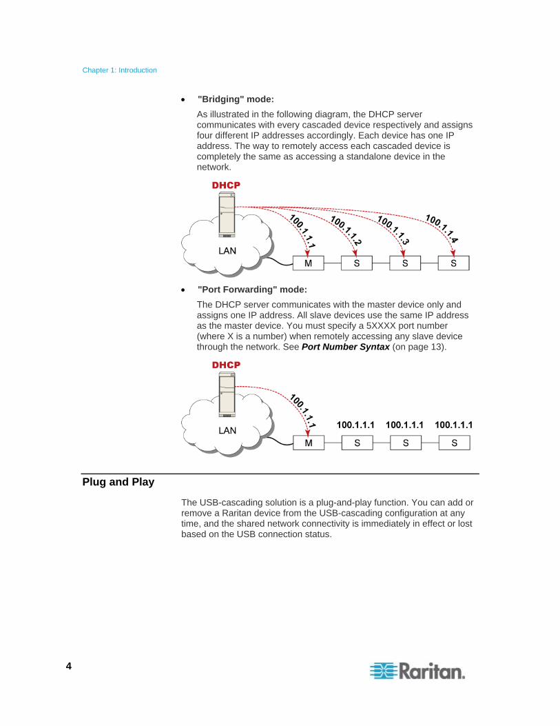
"Bridging" mode:
As illustrated in the following diagram, the DHCP server communicates with every cascaded device respectively and assigns four different IP addresses accordingly. Each device has one IP address. The way to remotely access each cascaded device is completely the same as accessing a standalone device in the network.
"Port Forwarding" mode:
The DHCP server communicates with the master device only and assigns one IP address. All slave devices use the same IP address as the master device. You must specify a 5XXXX port number (where X is a number) when remotely accessing any slave device through the network. See Port Number Syntax (on page 13).
Plug and Play
The USB-cascading solution is a plug-and-play function. You can add or remove a Raritan device from the USB-cascading configuration at any time, and the shared network connectivity is immediately in effect or lost based on the USB connection status.
USB-Cascading Applications Chapter 2
This chapter illustrates several USB-cascading scenarios using PDUs, and points out best practices and the condition the USB-cascading solution should be avoided.
In This Chapter
Appropriate Applications............................................................................5 Best Practices............................................................................................7 Inappropriate Applications .........................................................................7
Appropriate Applications
When intending to reduce the number of Ethernet connections or save networking costs, apply the USB-cascading solution.
In the USB-cascading configuration, all Raritan devices are cascaded using USB cables and only the first Raritan device in the chain is connected to the LAN.
The following illustrate a few USB-cascading scenarios using Zero U PDUs. Red lines in the diagrams represent USB connections.
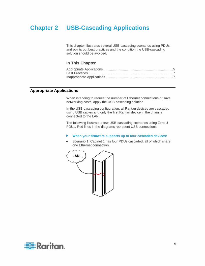
When your firmware supports up to four cascaded devices:
Scenario 1: Cabinet 1 has four PDUs cascaded, all of which share one Ethernet connection.
5
Chapter 2: USB-Cascading Applications
6
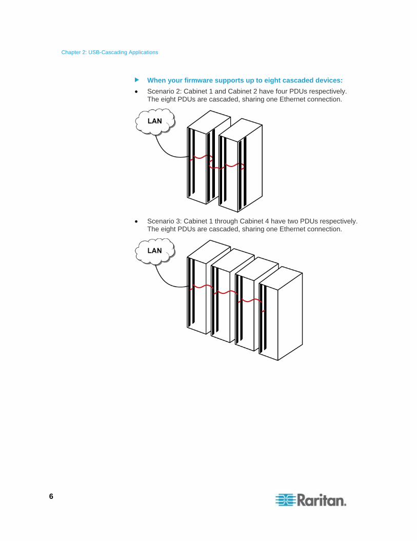
When your firmware supports up to eight cascaded devices:
Scenario 2: Cabinet 1 and Cabinet 2 have four PDUs respectively. The eight PDUs are cascaded, sharing one Ethernet connection.
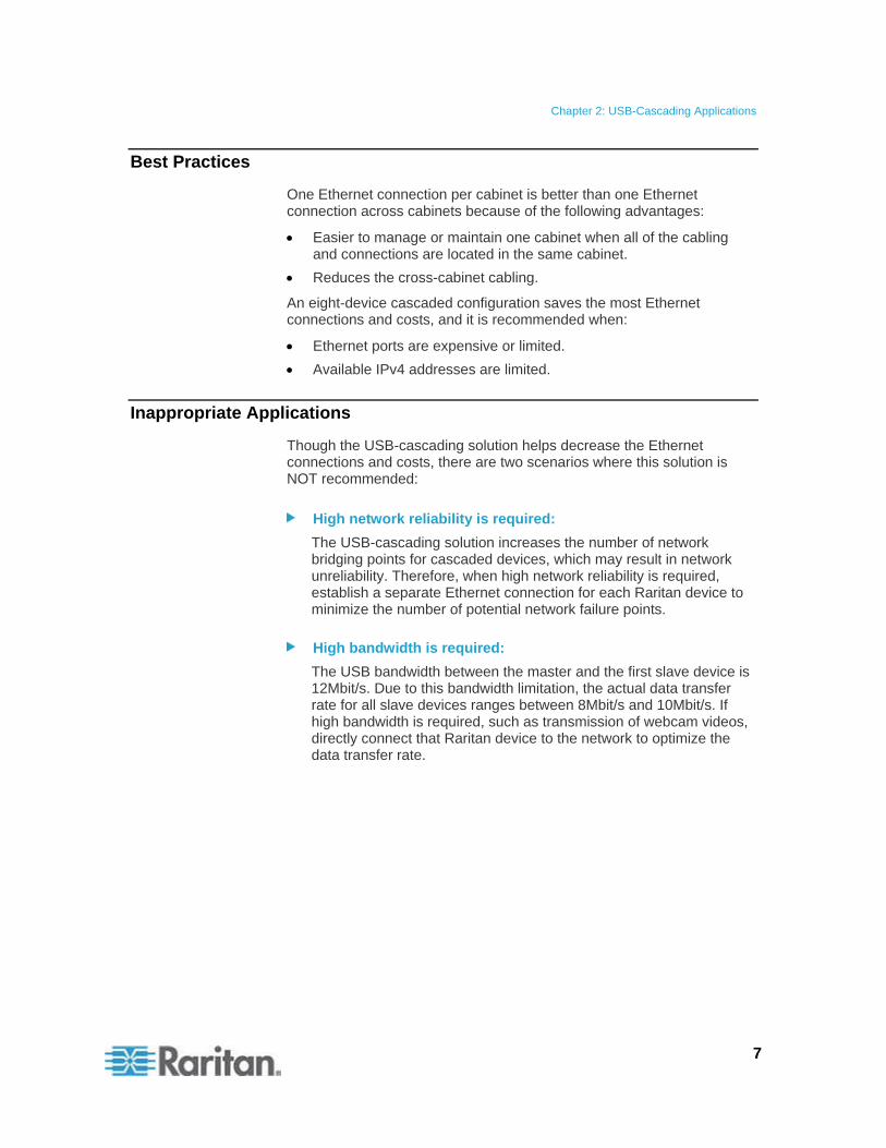
Scenario 3: Cabinet 1 through Cabinet 4 have two PDUs respectively. The eight PDUs are cascaded, sharing one Ethernet connection.
Chapter 2: USB-Cascading Applications
7
Best Practices
One Ethernet connection per cabinet is better than one Ethernet connection across cabinets because of the following advantages:
Easier to manage or maintain one cabinet when all of the cabling and connections are located in the same cabinet.
Reduces the cross-cabinet cabling.
An eight-device cascaded configuration saves the most Ethernet connections and costs, and it is recommended when:
Ethernet ports are expensive or limited.
Available IPv4 addresses are limited.
Inappropriate Applications
Though the USB-cascading solution helps decrease the Ethernet connections and costs, there are two scenarios where this solution is NOT recommended:
High network reliability is required:
The USB-cascading solution increases the number of network bridging points for cascaded devices, which may result in network unreliability. Therefore, when high network reliability is required, establish a separate Ethernet connection for each Raritan device to minimize the number of potential network failure points.
High bandwidth is required:
The USB bandwidth between the master and the first slave device is 12Mbit/s. Due to this bandwidth limitation, the actual data transfer rate for all slave devices ranges between 8Mbit/s and 10Mbit/s. If high bandwidth is required, such as transmission of webcam videos, directly connect that Raritan device to the network to optimize the data transfer rate.
USB-Cascading Instructions Chapter 3
This chapter describes the USB-cascading limitations, instructions and various methods to identify a cascaded Raritan device.
The USB-cascading configuration can operate in either cascading mode -- bridging or port forwarding, as long as it is running appropriate firmware. See Software Requirements (on page 2).
The first device in the USB-cascading configuration is the master device and the other are slave devices.
In This Chapter
USB-Cascading Restrictions .....................................................................8 Cascading the Raritan devices via USB....................................................9 Setting the Cascading Mode ...................................................................11
USB-Cascading Restrictions
Some restrictions apply regardless of the networking method used with the USB-cascading configuration, but some restrictions apply only when connecting to the wireless LAN.
Common restrictions:
All devices in the USB-cascading configuration must be running appropriate firmware. See Software Requirements (on page 2).
Depending on the firmware version, up to four or eight Raritan devices can be connected.
Only the master device must be connected to the LAN. Do NOT connect slave devices to the LAN via a standard network patch cable or a USB wireless LAN adapter.
Note: The Ethernet interface on slave devices is disabled automatically. See Ethernet Disabled Scenarios on Slave Devices (on page 55).
Appropriate networking methods vary based on the cascading mode. See Setting the Cascading Mode (on page 11).
The bridging mode supports the wired networking only.
The port forwarding mode supports both the wired and wireless networking.
8
Chapter 3: USB-Cascading Instructions
9
Your network switch's port security settings must support the USB-cascading solution. Make sure that packets forwarding is enabled for the Ethernet port where the master device is connected.
Restrictions only for the port forwarding mode over "wireless" LAN:
Port forwarding mode over wireless LAN is supported as of release 3.1.0. You must upgrade all devices in the chain to version 3.1.0 or higher if wireless networking is preferred.
You must use the Raritan USB WIFI wireless LAN adapter instead of other adapters for network connection.
A Raritan product with two USB-A ports must be the master device, such as PX3 or PX3TS. This is because one USB-A port is used to connect the USB wireless LAN adapter and the other is to connect a slave device.
No external USB hub is used with the master device.
Cascading the Raritan Devices via USB
Only specific types of Raritan products support the USB-cascading function. See Hardware Requirements (on page 1).
To cascade Raritan devices:
1. Verify that the Raritan devices to be cascaded are running appropriate firmware versions by choosing Maintenance > Device Information in the web interface.
If any device is running an inappropriate firmware, upgrade it. See Updating the Raritan Device Firmware (on page 42).
2. Select one of the devices as the master device.
When the port forwarding mode over wireless LAN is intended, the master device must be a Raritan product with two USB-A ports, such as PX3, EMX2-888, PX3TS or BCM2.
3. Connect the master device to the LAN via:
A standard network patch cable (CAT5e or higher) if the bridging mode is intended.
A standard network patch cable or a Raritan USB WIFI wireless LAN adapter if the port forwarding mode is intended. For information on the Raritan USB WIFI adapter, see USB Wireless LAN Adapters (on page 57).
For information on cascading modes, see Setting the Cascading Mode (on page 11).
4. Connect the USB-A port of the master device to the USB-B port of an additional Raritan device via a USB cable. This additional device is Slave 1.

Chapter 3: USB-Cascading Instructions
10
5. Connect Slave 1's USB-A port to the USB-B port of an additional Raritan device via a USB cable. The second additional device is Slave 2.
6. Repeat the same step to connect more slave devices.
If your firmware supports eight cascaded devices, you may cascade up to 7 slave devices. See Software Requirements (on page 2).
Number Device role
Master device
Slave 1
Slave 2
Slave 3
Chapter 3: USB-Cascading Instructions
11
Setting the Cascading Mode
This section only applies to the firmware versions that support two cascading modes. See Software Requirements (on page 2).
The Ethernet sharing mode applied to the USB-cascading configuration is either network bridging or port forwarding. This mode is determined by the master device. See Overview of the Cascading Modes (on page 3).
Only the Admin user or a user with the Administrator Privileges permission can configure the cascading mode.
To configure the cascading mode via the web interface:
1. Log in to the master device's web interface.
2. Choose Device Settings > USB Cascading. The USB Cascading Configuration dialog appears.
3. Verify that the "Position in cascaded chain" field shows 0 (Master), indicating that this Raritan device is the master device.
4. Select the preferred cascading mode in the "Cascading mode" field.
Bridging: Each device in the USB-cascading configuration is accessed with a different IP address. This is the default.
Port Forwarding: Each device in the USB-cascading configuration is accessed with the same IP address but with a different port number assigned. For details the port numbers, see Port Number Syntax (on page 13).
Note: If reversing or disconnecting the USB cable from a slave device, causing the slave device to become a master or standalone device, you must plug an Ethernet cable to it to update its USB-cascading status.
5. Click OK.
6. If selecting Port Forwarding, a list of port numbers for diverse networking protocols will be available on the "Protocol to Port Mapping" tab of each cascaded device.
Chapter 3: USB-Cascading Instructions
12
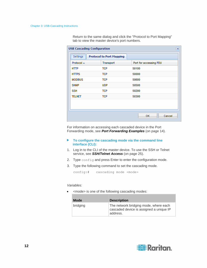
Return to the same dialog and click the "Protocol to Port Mapping" tab to view the master device's port numbers.
For information on accessing each cascaded device in the Port Forwarding mode, see Port Forwarding Examples (on page 14).
To configure the cascading mode via the command line interface (CLI):
1. Log in to the CLI of the master device. To use the SSH or Telnet service, see SSH/Telnet Access (on page 25).
2. Type config and press Enter to enter the configuration mode.
3. Type the following command to set the cascading mode.
config:# cascading mode <mode>
Variables:
<mode> is one of the following cascading modes:
Mode Description
bridging The network bridging mode, where each cascaded device is assigned a unique IP address.
Chapter 3: USB-Cascading Instructions
13
Mode Description
portForwarding The port forwarding mode, where every cascaded device in the chain shares the same IP address, with diverse port numbers assigned.
Port Number Syntax
In the Port Forwarding mode, all devices in the USB-cascading configuration share the same IP address. To access any cascaded device, you must assign an appropriate port number to it.
Master device: The port number is either 5NNXX or the standard TCP/UDP port.
Slave device: The port number is 5NNXX.
5NNXX port number syntax:
NN is a two-digit number representing the network protocol as shown below:
Protocols NN
HTTPS 00
HTTP 01
SSH 02
TELNET 03
SNMP 05
MODBUS 06
XX is a two-digit number representing the device position as shown below:
Position XX
Master device 00
Slave 1 01
Slave 2 02
Slave 3 03
Slave 4 04
Slave 5 05
Slave 6 06
Slave 7 07
Chapter 3: USB-Cascading Instructions
14
For example, to access the Slave 4 device via Modbus/TCP, the port number is 50604. See Port Forwarding Examples (on page 14) for further illustrations.
Tip: The full list of each cascaded device's port numbers can be retrieved from the web interface. See Setting the Cascading Mode (on page 11).
Standard TCP/UDP ports:
The master device can be also accessed through standard TCP/UDP ports as listed in the following table.
Protocols Port Numbers
HTTPS 443
HTTP 80
SSH 22
TELNET 23
SNMP 161
MODBUS 502
In the Port Forwarding mode, the Raritan device does NOT allow you to modify the standard TCP/UDP port configuration, including HTTP, HTTPS, SSH, Telnet, SNMP and Modbus/TCP.
Port Forwarding Examples
To access a cascaded device in the Port Forwarding mode, assign a port number to the IP address.
Master device: Assign proper 5NNXX port numbers or standard TCP/UDP ports. See Port Number Syntax (on page 13) for details.
Slave device: Assign proper 5NNXX port numbers.
Assumption: The Port Forwarding mode is applied to a USB-cascading configuration comprising three Raritan products. The IP address is 192.168.84.77.
Master device:
Position code for the master device is 00 so each port number is 5NN00 as shown below.
Protocols Port numbers
HTTPS 50000
HTTP 50100
Chapter 3: USB-Cascading Instructions
15
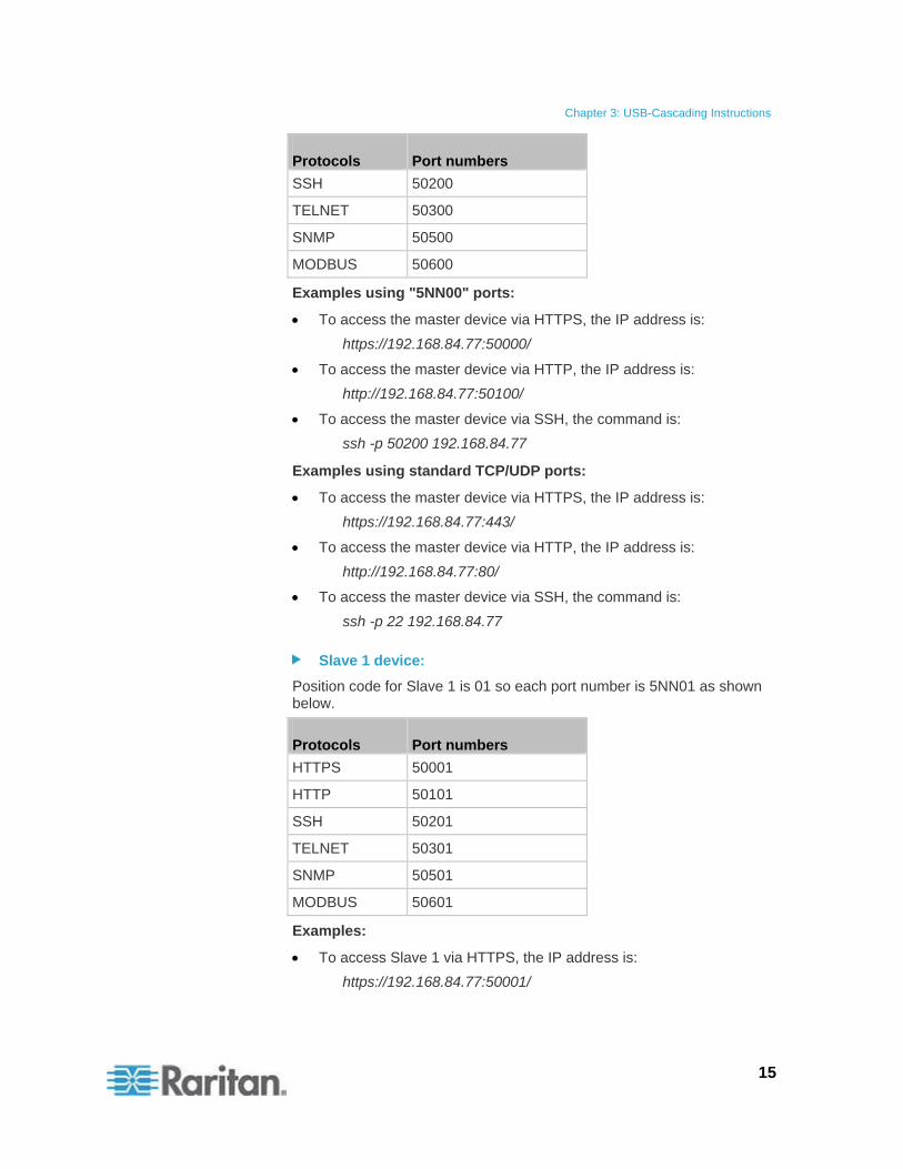
Protocols Port numbers
SSH 50200
TELNET 50300
SNMP 50500
MODBUS 50600
Examples using "5NN00" ports:
To access the master device via HTTPS, the IP address is:
https://192.168.84.77:50000/
To access the master device via HTTP, the IP address is:
http://192.168.84.77:50100/
To access the master device via SSH, the command is:
ssh -p 50200 192.168.84.77
Examples using standard TCP/UDP ports:
To access the master device via HTTPS, the IP address is:
https://192.168.84.77:443/
To access the master device via HTTP, the IP address is:
http://192.168.84.77:80/
To access the master device via SSH, the command is:
ssh -p 22 192.168.84.77
Slave 1 device:
Position code for Slave 1 is 01 so each port number is 5NN01 as shown below.
Protocols Port numbers
HTTPS 50001
HTTP 50101
SSH 50201
TELNET 50301
SNMP 50501
MODBUS 50601
Examples:
To access Slave 1 via HTTPS, the IP address is:
https://192.168.84.77:50001/
Chapter 3: USB-Cascading Instructions
16
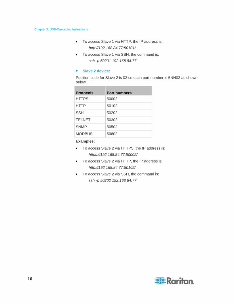
To access Slave 1 via HTTP, the IP address is:
http://192.168.84.77:50101/
To access Slave 1 via SSH, the command is:
ssh -p 50201 192.168.84.77
Slave 2 device:
Position code for Slave 2 is 02 so each port number is 5NN02 as shown below.
Protocols Port numbers
HTTPS 50002
HTTP 50102
SSH 50202
TELNET 50302
SNMP 50502
MODBUS 50602
Examples:
To access Slave 2 via HTTPS, the IP address is:
https://192.168.84.77:50002/
To access Slave 2 via HTTP, the IP address is:
http://192.168.84.77:50102/
To access Slave 2 via SSH, the command is:
ssh -p 50202 192.168.84.77
Network Access Chapter 4
The master device functions as the network bridge and can transmit IP packets between the LAN and all slave devices connected to it. Therefore, you can remotely access the master and every slave device via the Web, SNMP, SSH, or Telnet interface.
In This Chapter
Finding the IP Address ............................................................................17 HTTP/HTTPS Access..............................................................................22 SSH/Telnet Access..................................................................................25 SNMP Management ................................................................................26
Finding the IP Address
There are various ways to retrieve the IP address of a Raritan device.
Access the local console.
Use the device's MAC address and common networking tools.
Operate the front panel LCD display if the Raritan device is a PX3, PX3TS, BCM or EMX device.
Local Console
The IP address of the master or slave device is available in each device's local console, which uses the command line interface.
To access the local console, first connect the desired Raritan device to the computer using a serial RS-232 cable, and then use a terminal emulation program on the computer to access it.
You can also access a master device's local console via a USB connection. For details, see the Quick Setup Guide, Online Help or User Guide, which can be downloaded from Raritan website's Support page (http://www.raritan.com/support/).
You can use any terminal emulation programs for local access to the command line interface.
This section illustrates HyperTerminal, which is part of Windows operating systems prior to Windows Vista.
To get the IP address using HyperTerminal:
1. Connect your computer to the Raritan device via a local connection.
2. Launch HyperTerminal on your computer and open a console window. When the window first opens, it is blank.
Make sure the COM port settings use this configuration:
17
Chapter 4: Network Access
18
Bits per second = 115200 (115.2Kbps)
Data bits = 8
Stop bits = 1
Parity = None
Flow control = None
3. In the communications program, press Enter to send a carriage return to the Raritan device. Now you should see the Raritan device's IP address displayed in the terminal.
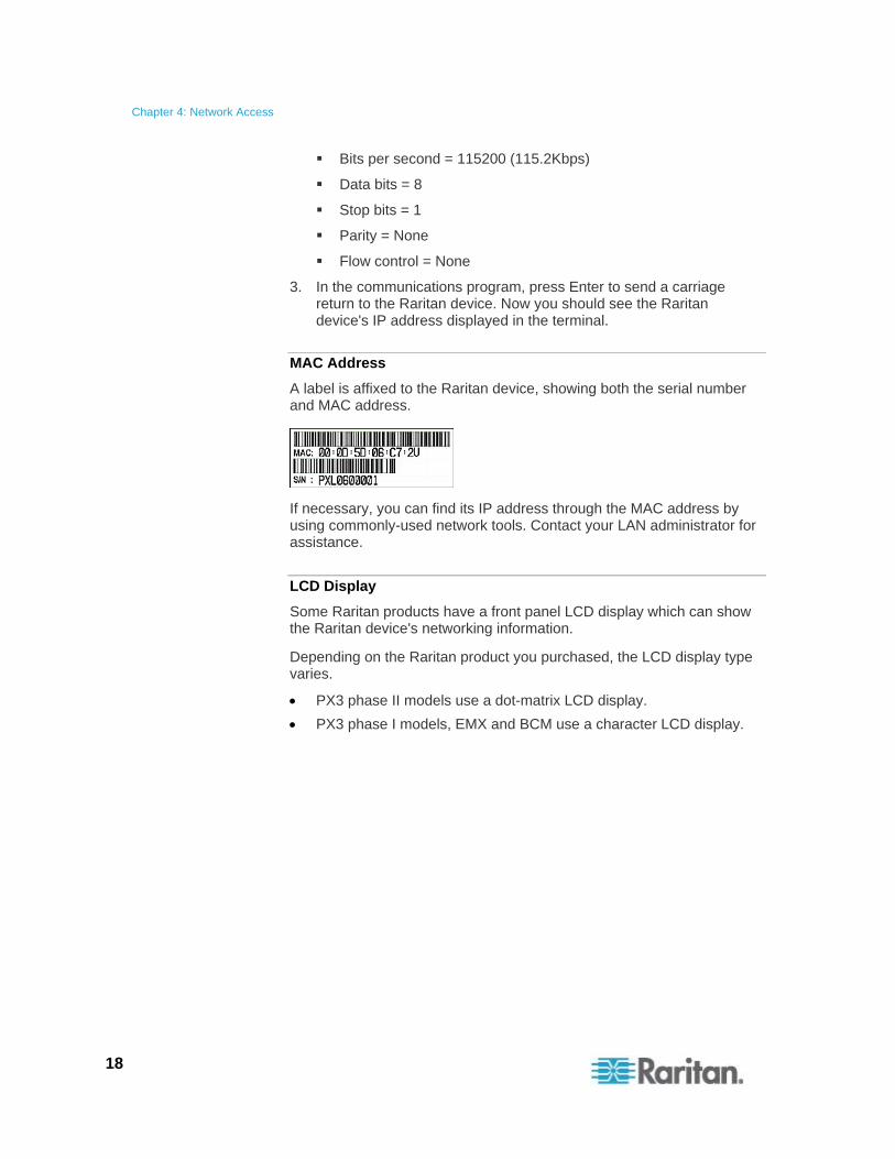
MAC Address
A label is affixed to the Raritan device, showing both the serial number and MAC address.
If necessary, you can find its IP address through the MAC address by using commonly-used network tools. Contact your LAN administrator for assistance.
LCD Display
Some Raritan products have a front panel LCD display which can show the Raritan device's networking information.
Depending on the Raritan product you purchased, the LCD display type varies.
PX3 phase II models use a dot-matrix LCD display.
PX3 phase I models, EMX and BCM use a character LCD display.
Chapter 4: Network Access
19
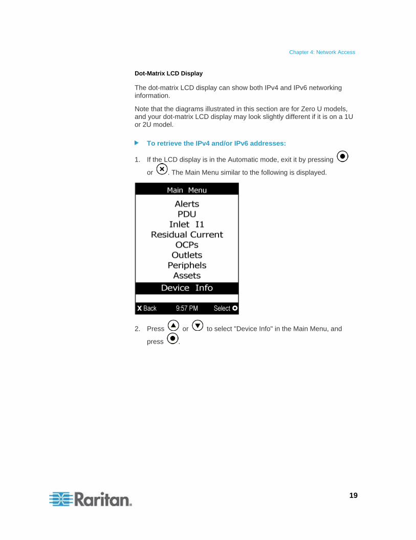
Dot-Matrix LCD Display
The dot-matrix LCD display can show both IPv4 and IPv6 networking information.
Note that the diagrams illustrated in this section are for Zero U models, and your dot-matrix LCD display may look slightly different if it is on a 1U or 2U model.
To retrieve the IPv4 and/or IPv6 addresses:
1. If the LCD display is in the Automatic mode, exit it by pressing
or . The Main Menu similar to the following is displayed.
2. Press or to select "Device Info" in the Main Menu, and
press .
Chapter 4: Network Access
20
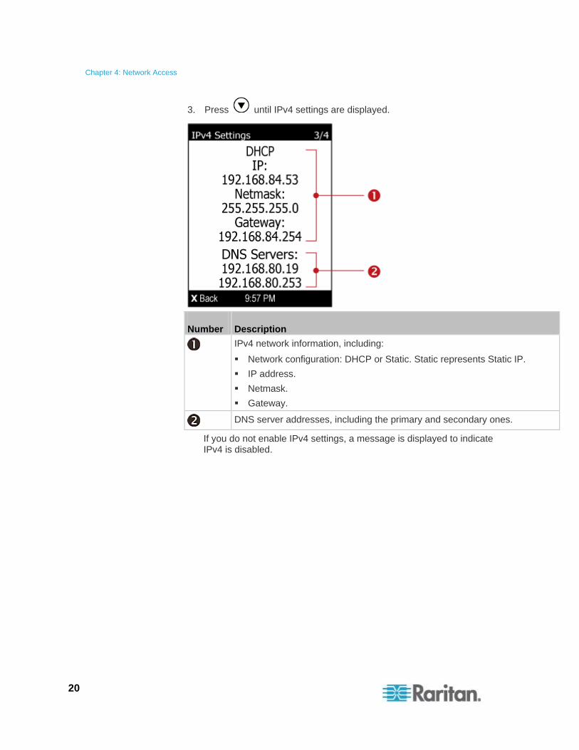
3. Press until IPv4 settings are displayed.
Number Description
IPv4 network information, including:
Network configuration: DHCP or Static. Static represents Static IP.
IP address.
Netmask.
Gateway.
DNS server addresses, including the primary and secondary ones.
If you do not enable IPv4 settings, a message is displayed to indicate IPv4 is disabled.
Chapter 4: Network Access
21
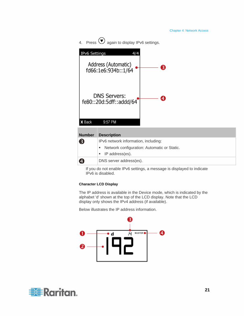
4. Press again to display IPv6 settings.
Number Description
IPv6 network information, including:
Network configuration: Automatic or Static.
IP address(es).
DNS server address(es).
If you do not enable IPv6 settings, a message is displayed to indicate IPv6 is disabled.
Character LCD Display
The IP address is available in the Device mode, which is indicated by the alphabet 'd' shown at the top of the LCD display. Note that the LCD display only shows the IPv4 address (if available).
Below illustrates the IP address information.
Chapter 4: Network Access
22
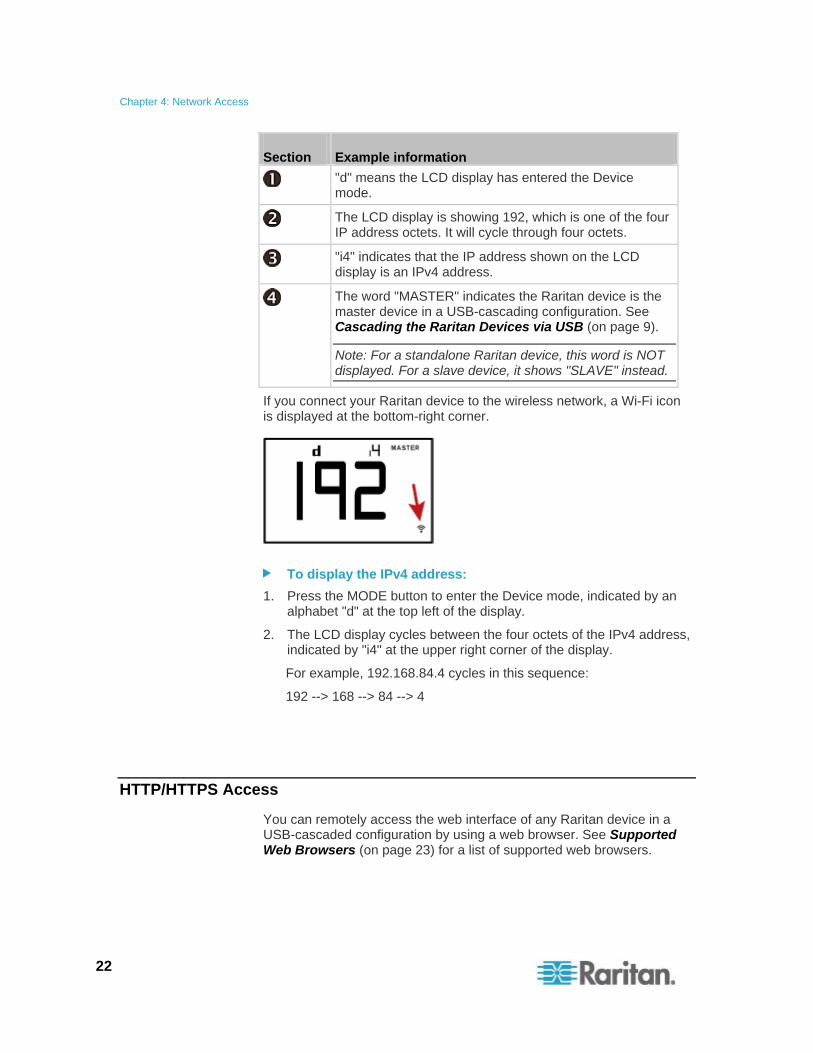
Section Example information
"d" means the LCD display has entered the Device mode.
The LCD display is showing 192, which is one of the four IP address octets. It will cycle through four octets.
"i4" indicates that the IP address shown on the LCD display is an IPv4 address.
The word "MASTER" indicates the Raritan device is the master device in a USB-cascading configuration. See Cascading the Raritan Devices via USB (on page 9).
Note: For a standalone Raritan device, this word is NOT displayed. For a slave device, it shows "SLAVE" instead.
If you connect your Raritan device to the wireless network, a Wi-Fi icon is displayed at the bottom-right corner.
To display the IPv4 address:
1. Press the MODE button to enter the Device mode, indicated by an alphabet "d" at the top left of the display.
2. The LCD display cycles between the four octets of the IPv4 address, indicated by "i4" at the upper right corner of the display.
For example, 192.168.84.4 cycles in this sequence:
192 --> 168 --> 84 --> 4
HTTP/HTTPS Access
You can remotely access the web interface of any Raritan device in a USB-cascaded configuration by using a web browser. See Supported Web Browsers (on page 23) for a list of supported web browsers.
Chapter 4: Network Access
23
Supported Web Browsers
The following web browsers can be used to access a Raritan device’s web interface. For details, see the online help or User Guide for your Raritan device.
Internet Explorer®
Firefox®
Safari®
Google® Chrome®
Android
IOS
Windows Edge
Using the Web Browser
The web interface allows a maximum of 16 users to log in simultaneously.
You must enable JavaScript in the web browser for proper operation.
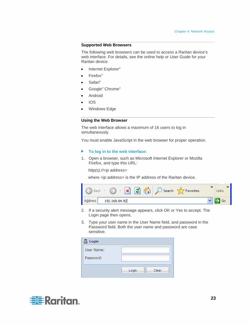
To log in to the web interface:
1. Open a browser, such as Microsoft Internet Explorer or Mozilla Firefox, and type this URL:
http(s)://<ip address>
where <ip address> is the IP address of the Raritan device.
2. If a security alert message appears, click OK or Yes to accept. The Login page then opens.
3. Type your user name in the User Name field, and password in the Password field. Both the user name and password are case sensitive.
Chapter 4: Network Access
24
Note: If needed, click Clear to clear either the inputs or any error message that appears.
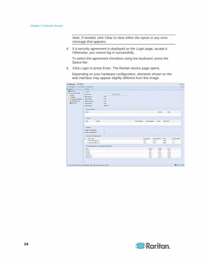
4. If a security agreement is displayed on the Login page, accept it. Otherwise, you cannot log in successfully.
To select the agreement checkbox using the keyboard, press the Space bar.
5. Click Login or press Enter. The Raritan device page opens.
Depending on your hardware configuration, elements shown on the web interface may appear slightly different from this image.
Chapter 4: Network Access
25
Note: The IP address to access a slave device in the USB-cascading configuration where the port forwarding mode is applied is a combination of the IP address and the port number. See Port Forwarding Examples (on page 14).
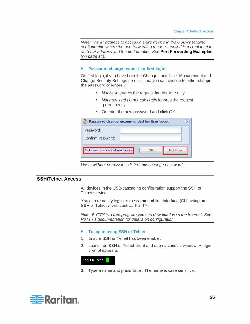
Password change request for first login:
On first login, if you have both the Change Local User Management and Change Security Settings permissions, you can choose to either change the password or ignore it.
Not Now ignores the request for this time only.
Not now, and do not ask again ignores the request permanently.
Or enter the new password and click OK.
Users without permissions listed must change password.
SSH/Telnet Access
All devices in the USB-cascading configuration support the SSH or Telnet service.
You can remotely log in to the command line interface (CLI) using an SSH or Telnet client, such as PuTTY.
Note: PuTTY is a free program you can download from the Internet. See PuTTY's documentation for details on configuration.
To log in using SSH or Telnet:
1. Ensure SSH or Telnet has been enabled.
2. Launch an SSH or Telnet client and open a console window. A login prompt appears.
3. Type a name and press Enter. The name is case sensitive.
Chapter 4: Network Access
26
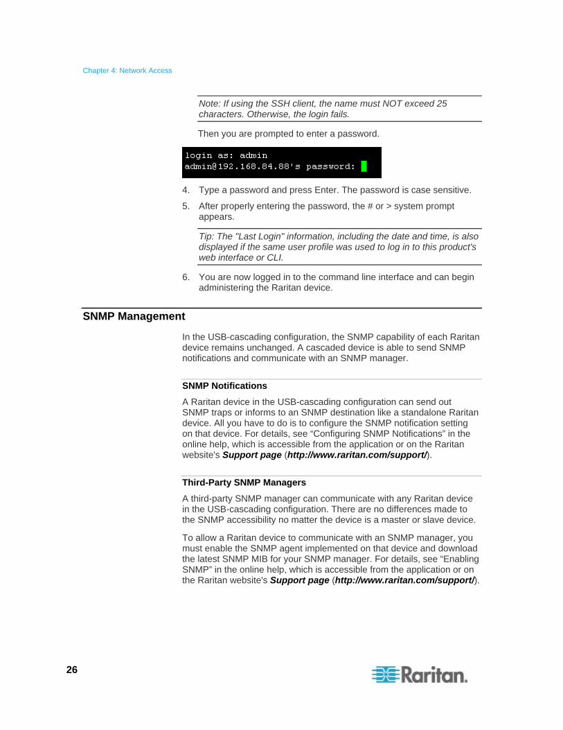
Note: If using the SSH client, the name must NOT exceed 25 characters. Otherwise, the login fails.
Then you are prompted to enter a password.
4. Type a password and press Enter. The password is case sensitive.
5. After properly entering the password, the # or > system prompt appears.
Tip: The "Last Login" information, including the date and time, is also displayed if the same user profile was used to log in to this product's web interface or CLI.
6. You are now logged in to the command line interface and can begin administering the Raritan device.
SNMP Management
In the USB-cascading configuration, the SNMP capability of each Raritan device remains unchanged. A cascaded device is able to send SNMP notifications and communicate with an SNMP manager.
SNMP Notifications
A Raritan device in the USB-cascading configuration can send out SNMP traps or informs to an SNMP destination like a standalone Raritan device. All you have to do is to configure the SNMP notification setting on that device. For details, see “Configuring SNMP Notifications” in the online help, which is accessible from the application or on the Raritan website's Support page (http://www.raritan.com/support/).
Third-Party SNMP Managers
A third-party SNMP manager can communicate with any Raritan device in the USB-cascading configuration. There are no differences made to the SNMP accessibility no matter the device is a master or slave device.
To allow a Raritan device to communicate with an SNMP manager, you must enable the SNMP agent implemented on that device and download the latest SNMP MIB for your SNMP manager. For details, see “Enabling SNMP” in the online help, which is accessible from the application or on the Raritan website's Support page (http://www.raritan.com/support/).
Identifying Cascaded Devices Chapter 5
You can retrieve a device's USB-cascading status from one of these interfaces:
Web interface: Accessible via HTTP or HTTPS.
Command line interface (CLI): Accessible via SSH, Telnet or the serial interface.
SNMP: An SNMP manager is required.
LCD display: Use the front panel LCD display if your Raritan device has it.
Before remotely accessing a Raritan device, you need to get its IP address. See Finding the IP Address (on page 17).
In This Chapter
Using the Web Interface ..........................................................................27 Using the CLI...........................................................................................34 Using the SNMP ......................................................................................36 Using the LCD Display ............................................................................38
Using the Web Interface
This section explains how to identify a cascaded device through the web interface.
The web interface differs depending on your firmware versions. See Software Requirements (on page 2) for information on different firmware versions.
When your firmware supports two cascading modes:
1. Log in to the desired Raritan device using a supported web browser. See HTTP/HTTPS Access (on page 22).
2. Choose Maintenance > Device Information.
3. Select the Network tab and locate the Interface section. The Interface section contains four read-only fields as listed below.
27

Chapter 5: Identifying Cascaded Devices
28
Fields Description
Networking Mode Indicates how the Raritan device is connected to the LAN.
Wired: The device is connected to the LAN through a standard network cable.
Wireless: The device is connected to the LAN through a supported USB wireless LAN adapter. See USB Wireless LAN Adapters (on page 57).
XXX (USB): XXX represents Wired or Wireless. The device is connected to the LAN through a USB-cascading configuration. That is, it is a slave device.
Cascading Mode Shows the cascading mode applied. See Setting the Cascading Mode (on page 11).
Cascade Position Indicates the position of the Raritan device in the USB-cascading configuration.
0 (zero) represents the master device.
A non-zero number represents a slave device. 1 is Slave 1, 2 is Slave 2, 3 is Slave 3 and so on.
This field is NOT available on a standalone Raritan device.
Cascaded Device Connected
Indicates whether the presence of a slave device is detected on the USB-A port.
yes: Connection to a slave device is detected.
no: NO connection to a slave device is detected.
Chapter 5: Identifying Cascaded Devices
29
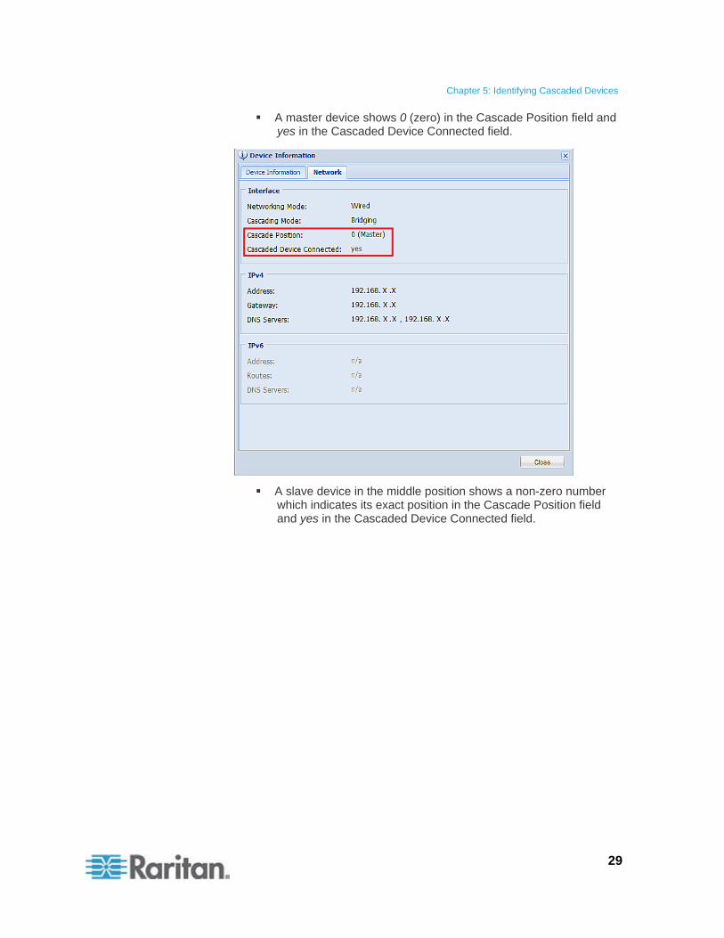
A master device shows 0 (zero) in the Cascade Position field and yes in the Cascaded Device Connected field.
A slave device in the middle position shows a non-zero number which indicates its exact position in the Cascade Position field and yes in the Cascaded Device Connected field.
Chapter 5: Identifying Cascaded Devices
30
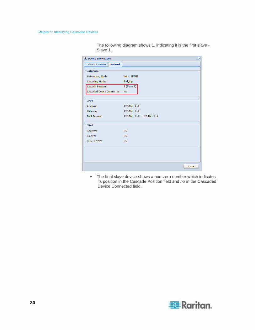
The following diagram shows 1, indicating it is the first slave - Slave 1.
The final slave device shows a non-zero number which indicates its position in the Cascade Position field and no in the Cascaded Device Connected field.
Chapter 5: Identifying Cascaded Devices
31
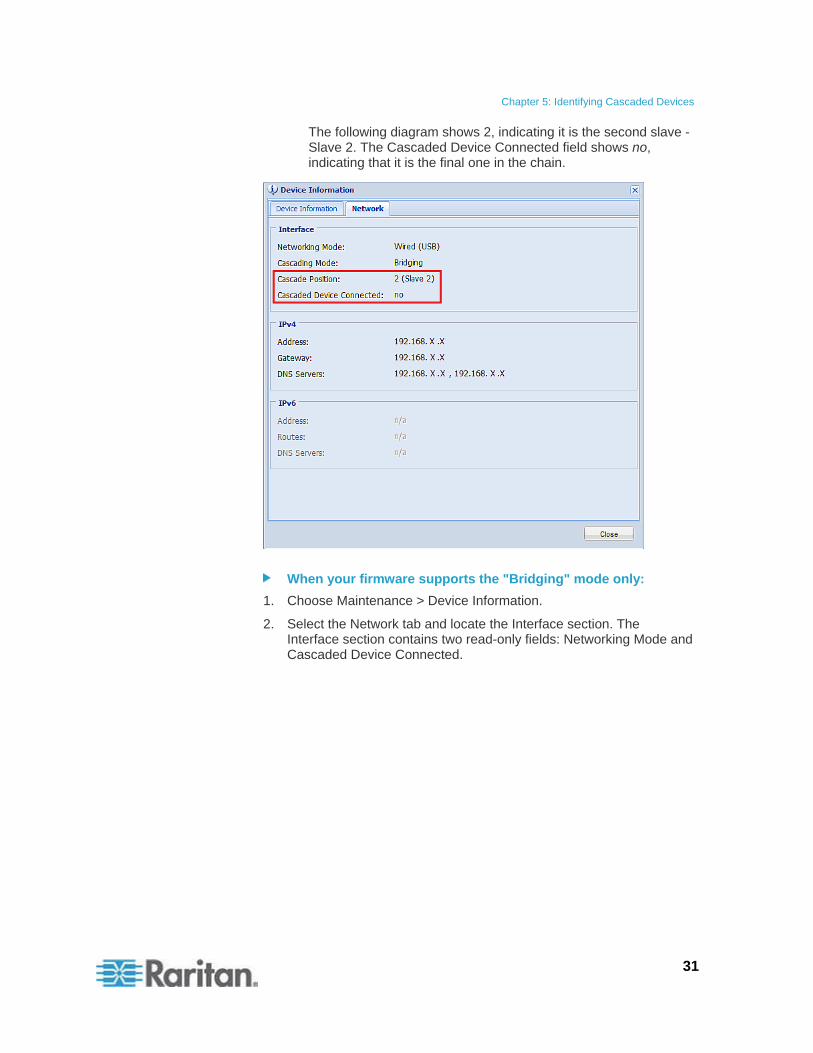
The following diagram shows 2, indicating it is the second slave - Slave 2. The Cascaded Device Connected field shows no, indicating that it is the final one in the chain.
When your firmware supports the "Bridging" mode only:
1. Choose Maintenance > Device Information.
2. Select the Network tab and locate the Interface section. The Interface section contains two read-only fields: Networking Mode and Cascaded Device Connected.
Chapter 5: Identifying Cascaded Devices
32
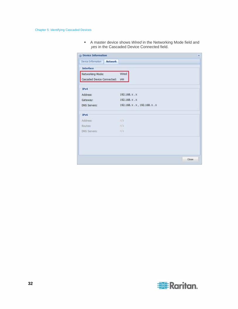
A master device shows Wired in the Networking Mode field and yes in the Cascaded Device Connected field.
Chapter 5: Identifying Cascaded Devices
33
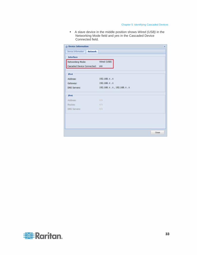
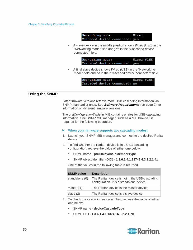
A slave device in the middle position shows Wired (USB) in the Networking Mode field and yes in the Cascaded Device Connected field.
Chapter 5: Identifying Cascaded Devices
34
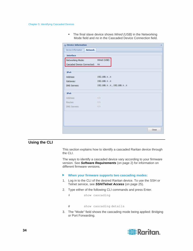
The final slave device shows Wired (USB) in the Networking Mode field and no in the Cascaded Device Connection field.
Using the CLI
This section explains how to identify a cascaded Raritan device through the CLI.
The ways to identify a cascaded device vary according to your firmware version. See Software Requirements (on page 2) for information on different firmware versions.
When your firmware supports two cascading modes:
1. Log in to the CLI of the desired Raritan device. To use the SSH or Telnet service, see SSH/Telnet Access (on page 25).
2. Type either of the following CLI commands and press Enter.
# show cascading
# show cascading details
3. The "Mode" field shows the cascading mode being applied: Bridging or Port Forwarding.
Chapter 5: Identifying Cascaded Devices
35
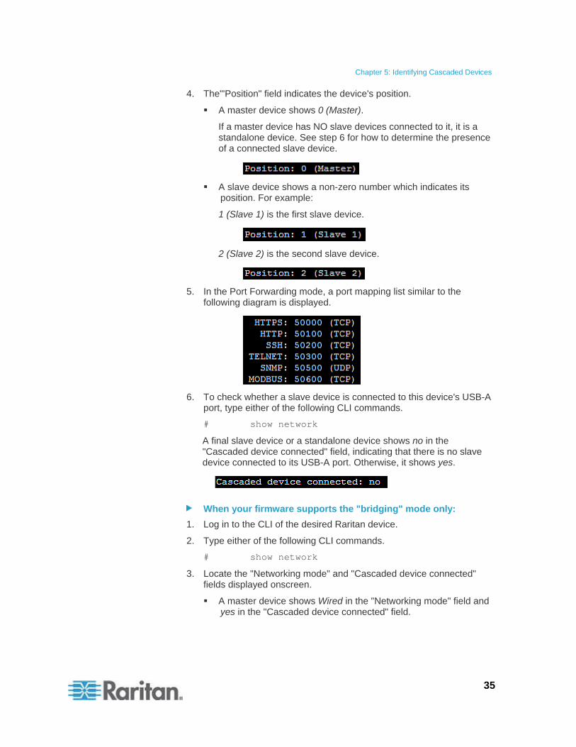
4. The"'Position" field indicates the device's position.
A master device shows 0 (Master).
If a master device has NO slave devices connected to it, it is a standalone device. See step 6 for how to determine the presence of a connected slave device.
A slave device shows a non-zero number which indicates its position. For example:
1 (Slave 1) is the first slave device.
2 (Slave 2) is the second slave device.
5. In the Port Forwarding mode, a port mapping list similar to the following diagram is displayed.
6. To check whether a slave device is connected to this device's USB-A port, type either of the following CLI commands.
# show network
A final slave device or a standalone device shows no in the "Cascaded device connected" field, indicating that there is no slave device connected to its USB-A port. Otherwise, it shows yes.
When your firmware supports the "bridging" mode only:
1. Log in to the CLI of the desired Raritan device.
2. Type either of the following CLI commands.
# show network
3. Locate the "Networking mode" and "Cascaded device connected" fields displayed onscreen.
A master device shows Wired in the "Networking mode" field and yes in the "Cascaded device connected" field.
Chapter 5: Identifying Cascaded Devices
36
A slave device in the middle position shows Wired (USB) in the "Networking mode" field and yes in the "Cascaded device connected" field.
A final slave device shows Wired (USB) in the "Networking mode" field and no in the "Cascaded device connected" field.
Using the SNMP
Later firmware versions retrieve more USB-cascading information via SNMP than earlier ones. See Software Requirements (on page 2) for information on different firmware versions.
The unitConfigurationTable in MIB contains entries for USB-cascading information. One SNMP MIB manager, such as a MIB browser, is required for the following operation.
When your firmware supports two cascading modes:
1. Launch your SNMP MIB manager and connect to the desired Raritan device.
2. To find whether the Raritan device is in a USB-cascading configuration, retrieve the value of either one below:
SNMP name - pduDaisychainMemberType
SNMP object identifier (OID) - 1.3.6.1.4.1.13742.6.3.2.2.1.41
One of the values in the following table is returned.
SNMP value Description
standalone (0) The Raritan device is not in the USB-cascading configuration. It is a standalone device.
master (1) The Raritan device is the master device.
slave (2) The Raritan device is a slave device.
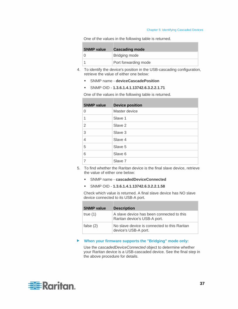
3. To check the cascading mode applied, retrieve the value of either one below:
SNMP name - deviceCascadeType
SNMP OID - 1.3.6.1.4.1.13742.6.3.2.2.1.70
Chapter 5: Identifying Cascaded Devices
37
One of the values in the following table is returned.
SNMP value Cascading mode
0 Bridging mode
1 Port forwarding mode
4. To identify the device's position in the USB-cascading configuration, retrieve the value of either one below:
SNMP name - deviceCascadePosition
SNMP OID - 1.3.6.1.4.1.13742.6.3.2.2.1.71
One of the values in the following table is returned.
SNMP value Device position
0 Master device
1 Slave 1
2 Slave 2
3 Slave 3
4 Slave 4
5 Slave 5
6 Slave 6
7 Slave 7
5. To find whether the Raritan device is the final slave device, retrieve the value of either one below:
SNMP name - cascadedDeviceConnected
SNMP OID - 1.3.6.1.4.1.13742.6.3.2.2.1.58
Check which value is returned. A final slave device has NO slave device connected to its USB-A port.
SNMP value Description
true (1) A slave device has been connected to this Raritan device's USB-A port.
false (2) No slave device is connected to this Raritan device's USB-A port.
When your firmware supports the "Bridging" mode only:
Use the cascadedDeviceConnected object to determine whether your Raritan device is a USB-cascaded device. See the final step in the above procedure for details.
Chapter 5: Identifying Cascaded Devices
38
Using the LCD Display
Some Raritan products have a front panel LCD display which can show USB-cascading information, such as the device position.
Depending on the Raritan product you purchased, the LCD display type varies.
PX3 phase II models use a dot-matrix LCD display.
PX3 phase I models, EMX and BCM use a character LCD display.
Dot-Matrix LCD Display
On the dot-matrix LCD display, the USB-cascading information indicates the cascading mode, position and the presence of a connected slave device.
Note that the diagrams illustrated in this section are for Zero U models, and your dot-matrix LCD display may look slightly different if it is on a 1U or 2U model.
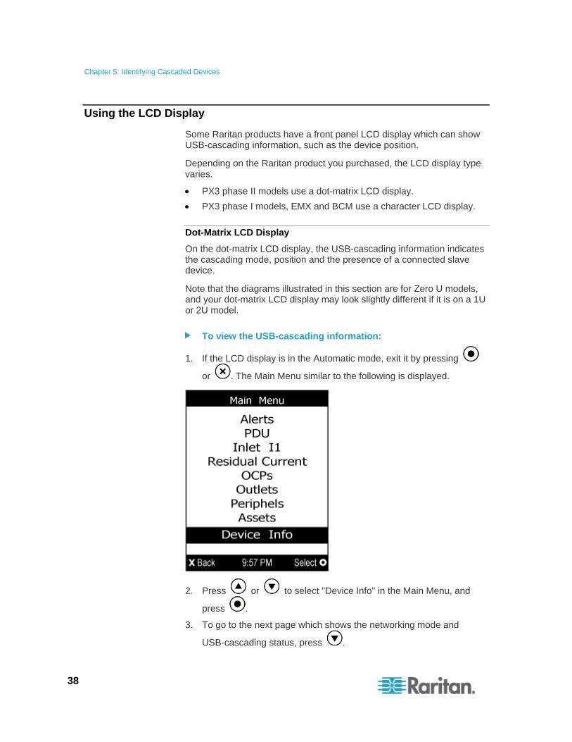
To view the USB-cascading information:
1. If the LCD display is in the Automatic mode, exit it by pressing
or . The Main Menu similar to the following is displayed.
2. Press or to select "Device Info" in the Main Menu, and
press .
3. To go to the next page which shows the networking mode and
USB-cascading status, press .
Chapter 5: Identifying Cascaded Devices
39
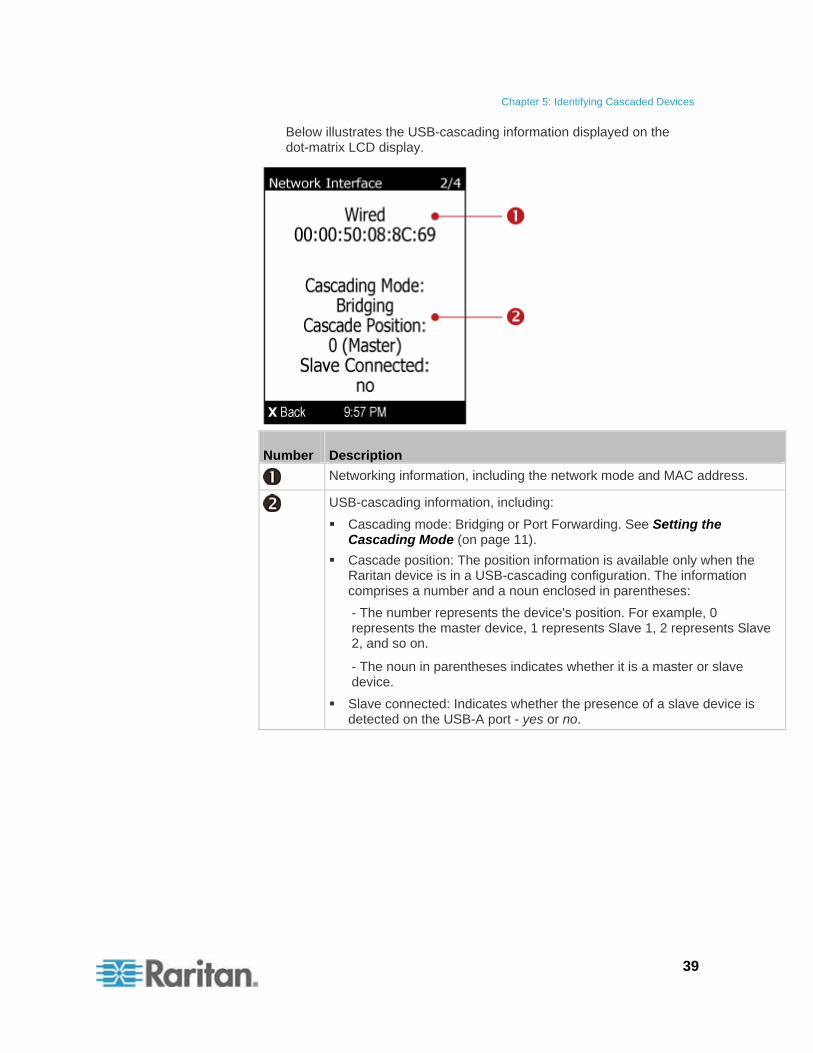
Below illustrates the USB-cascading information displayed on the dot-matrix LCD display.
Number Description
Networking information, including the network mode and MAC address.
USB-cascading information, including:
Cascading mode: Bridging or Port Forwarding. See Setting the Cascading Mode (on page 11).
Cascade position: The position information is available only when the Raritan device is in a USB-cascading configuration. The information comprises a number and a noun enclosed in parentheses:
- The number represents the device's position. For example, 0 represents the master device, 1 represents Slave 1, 2 represents Slave 2, and so on.
- The noun in parentheses indicates whether it is a master or slave device.
Slave connected: Indicates whether the presence of a slave device is detected on the USB-A port - yes or no.
Chapter 5: Identifying Cascaded Devices
40
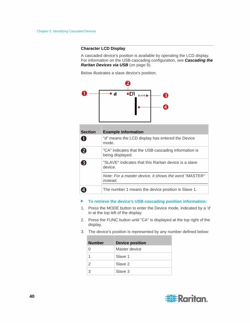
Character LCD Display
A cascaded device's position is available by operating the LCD display. For information on the USB-cascading configuration, see Cascading the Raritan Devices via USB (on page 9).
Below illustrates a slave device's position.
Section Example information
"d" means the LCD display has entered the Device mode.
"CA" indicates that the USB-cascading information is being displayed.
"SLAVE" indicates that this Raritan device is a slave device.
Note: For a master device, it shows the word "MASTER" instead.
The number 1 means the device position is Slave 1.
To retrieve the device's USB-cascading position information:
1. Press the MODE button to enter the Device mode, indicated by a 'd' in at the top left of the display.
2. Press the FUNC button until "CA" is displayed at the top right of the display.
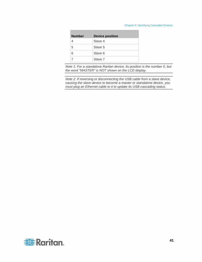
3. The device's position is represented by any number defined below:
Number Device position
0 Master device
1 Slave 1
2 Slave 2
3 Slave 3
Chapter 5: Identifying Cascaded Devices
41
Number Device position
4 Slave 4
5 Slave 5
6 Slave 6
7 Slave 7
Note 1: For a standalone Raritan device, its position is the number 0, but the word "MASTER" is NOT shown on the LCD display.
Note 2: If reversing or disconnecting the USB cable from a slave device, causing the slave device to become a master or standalone device, you must plug an Ethernet cable to it to update its USB-cascading status.
Updating the Raritan Device Firmware
Chapter 6
You can upgrade each individual Raritan device in the USB-cascading configuration through the web interface. The upgrade procedure is completely identical to the procedure for a standalone Raritan device.
Firmware files are available on Raritan website's Support page (http://www.raritan.com/support/).
To update the firmware:
1. Choose Maintenance > Update Firmware. The Update Firmware dialog appears.
2. In the Firmware File field, click Browse to select an appropriate firmware file.
3. Click Upload. A progress bar appears to indicate the upload status.
4. When the upload is complete, version information of both the existing firmware and uploaded firmware is shown, providing you a last chance to terminate the update.
5. To view the certificate of the uploaded firmware, click View Certificate. Optional.
6. To proceed with the update, click Update Firmware. The update may take several minutes.
Warning: Do NOT power off the Raritan device during the update.
During the firmware update:
A progress bar appears in the web interface, indicating the update status.
The front panel display on the Raritan device shows three digits: 'FuP' or 'FUP.'
Exception: A PX3 Phase II model shows the upgrade progress in percent instead of FUP on its LCD display.
No users can successfully log in to the Raritan device.
The user management operation, if any, is forced to suspend.
7. When the update is complete, a message appears, indicating the update is successful.
8. The Raritan device resets, and the Login page re-appears. You can now log in and resume your operation.
42
Chapter 6: Updating the Raritan Device Firmware
43
Note: If you are using the Raritan device with an SNMP manager, download its MIB again after the firmware update to ensure your SNMP manager has the correct MIB for the latest release you are using.
Configuring Network Settings Appendix A
Network settings can be configured through either the web interface or command line interface (CLI). This appendix only shows basic operation. For details, see the online help or User Guide for your Raritan device.
If the bridging mode is intended, you must configure the network settings of each cascaded device respectively.
If the port forwarding mode is intended, you only need to configure the master device's network settings.
In This Chapter
Configuration via Web Interface ..............................................................44 Configuration via CLI ...............................................................................45
Configuration via Web Interface
When you are able to connect to the master or slave device over Internet, you can access its web interface to change the network settings.
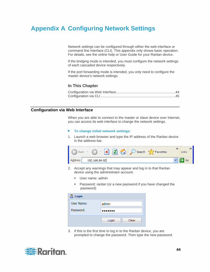
To change initial network settings:
1. Launch a web browser and type the IP address of the Raritan device in the address bar.
2. Accept any warnings that may appear and log in to that Raritan device using the administrator account.
User name: admin
Password: raritan (or a new password if you have changed the password)
3. If this is the first time to log in to the Raritan device, you are prompted to change the password. Then type the new password.
44
Appendix A: Configuring Network Settings
45
4. Choose Device Settings > Network. The Network Configuration dialog appears.
5. Click the IP Protocol tab to enable IPv4, IPv6 or both.
6. Depending on which IP protocol has been enabled in the above step, click the corresponding tab to change the IP address settings.
If IPv4 is enabled, click the IPv4 Settings tab.
If IPv6 is enabled, click the IPv6 Settings tab.
If both are enabled, click both tabs to configure IP addresses respectively.
Configuration via CLI
If you want to configure a master or slave device's network settings via CLI, you must connect that device to a computer via a serial RS-232 connection.
You can also access the master device's CLI through a USB connection. For details, see the Quick Setup Guide, Online Help or User Guide, which can be downloaded from Raritan website's Support page (http://www.raritan.com/support/).
To configure network settings via CLI:
1. On the computer connected to the Raritan device, open a communications program such as HyperTerminal or PuTTY.
2. Select the appropriate COM port, and set the following port settings:
Bits per second = 115200 (115.2Kbps)
Data bits = 8
Stop bits = 1
Parity = None
Flow control = None
Tip: For a USB connection, you can determine the COM port by choosing Control Panel > System > Hardware > Device Manager, and locating the "Serial Console" under the Ports group.
3. In the communications program, press Enter to send a carriage return to the Raritan device.
4. The Raritan device prompts you to log in. Both user name and password are case sensitive.
a. Username: admin
b. Password: raritan (or a new password if you have changed it).
5. If prompted to change the default password, change or ignore it.
Appendix A: Configuring Network Settings
46
To change it, follow onscreen instructions to type your new password.
To ignore it, simply press Enter.
6. The # prompt appears.
7. Type config and press Enter.
8. To configure network settings, type appropriate commands and press Enter. All commands are case sensitive.
a. To set the networking mode, type this command:
network mode <mode>
where <mode> is wired (default) or wireless.
b. For the wired network mode, you may configure the LAN interface settings. In most scenarios, the default setting (auto) works well and should not be changed unless required.
To set Use this command
LAN interface speed
network interface LANInterfaceSpeed <option>
<option> = auto, 10Mbps, or 100Mbps.
LAN interface duplex mode
network interface LANInterfaceDuplexMode <mode>
<mode> = half, full or auto.
Tip: You can combine multiple commands to configure multiple parameters at a time. For example, network interface LANInterfaceSpeed <option> LANInterfaceDuplexMode <mode>
c. For the wireless network mode, you must configure the Service Set Identifier (SSID) parameter.
To set Use this command
SSID network wireless SSID <ssid>
<ssid> = SSID string
If necessary, configure more wireless parameters shown in the following table.
Appendix A: Configuring Network Settings
47
To set Use this command
BSSID network wireless BSSID <bssid>
<bssid> = AP MAC address or none
Authentication method
network wireless authMethod <method>
<method> = psk or eap
PSK network wireless PSK <psk>
<psk> = PSK string
EAP outer authentication
network wireless eapOuterAuthentication <outer_auth>
<outer_auth> = PEAP
EAP inner authentication
network wireless eapInnerAuthentication <inner_auth>
<inner_auth> = MSCHAPv2
EAP identity network wireless eapIdentity <identity>
<identity> = your user name for EAP authentication
EAP passord network wireless eapPassword
When prompted to enter the password for EAP authentication, type the password.
EAP CA certificate
network wireless eapCACertificate
When prompted to enter the CA certificate, open the certificate with a text editor, copy and paste the content into the communications program.
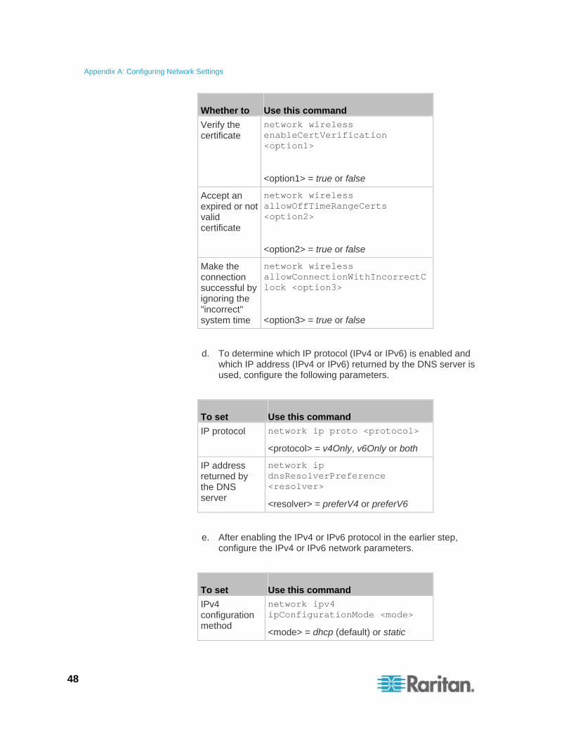
The content to be copied from the CA certificate does NOT include the first line containing "BEGIN CERTIFICATE" and the final line containing "END CERTIFICATE." If a certificate is installed, configure the following:
Appendix A: Configuring Network Settings
48
Whether to Use this command
Verify the certificate
network wireless enableCertVerification <option1>
<option1> = true or false
Accept an expired or not valid certificate
network wireless allowOffTimeRangeCerts <option2>
<option2> = true or false
Make the connection successful by ignoring the "incorrect" system time
network wireless allowConnectionWithIncorrectClock <option3>
<option3> = true or false
d. To determine which IP protocol (IPv4 or IPv6) is enabled and which IP address (IPv4 or IPv6) returned by the DNS server is used, configure the following parameters.
To set Use this command
IP protocol network ip proto <protocol>
<protocol> = v4Only, v6Only or both
IP address returned by the DNS server
network ip dnsResolverPreference <resolver>
<resolver> = preferV4 or preferV6
e. After enabling the IPv4 or IPv6 protocol in the earlier step, configure the IPv4 or IPv6 network parameters.
To set Use this command
IPv4 configuration method
network ipv4 ipConfigurationMode <mode>
<mode> = dhcp (default) or static
Appendix A: Configuring Network Settings
49
To set Use this command
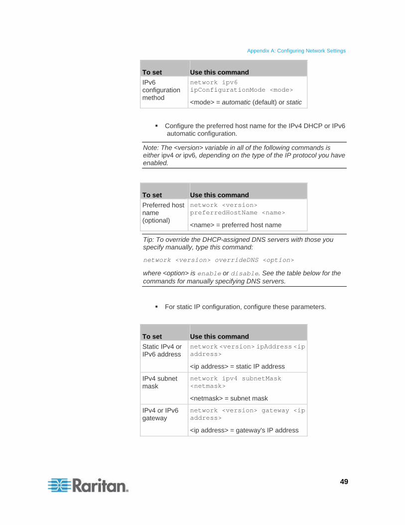
IPv6 configuration method
network ipv6 ipConfigurationMode <mode>
<mode> = automatic (default) or static
Configure the preferred host name for the IPv4 DHCP or IPv6 automatic configuration.
Note: The <version> variable in all of the following commands is either ipv4 or ipv6, depending on the type of the IP protocol you have enabled.
To set Use this command
Preferred host name (optional)
network <version> preferredHostName <name>
<name> = preferred host name
Tip: To override the DHCP-assigned DNS servers with those you specify manually, type this command:
network <version> overrideDNS <option>
where <option> is enable or disable. See the table below for the commands for manually specifying DNS servers.
For static IP configuration, configure these parameters.
To set Use this command
Static IPv4 or IPv6 address
network <version> ipAddress <ip address>
<ip address> = static IP address
IPv4 subnet mask
network ipv4 subnetMask <netmask>
<netmask> = subnet mask
IPv4 or IPv6 gateway
network <version> gateway <ip address>
<ip address> = gateway's IP address
Appendix A: Configuring Network Settings
50
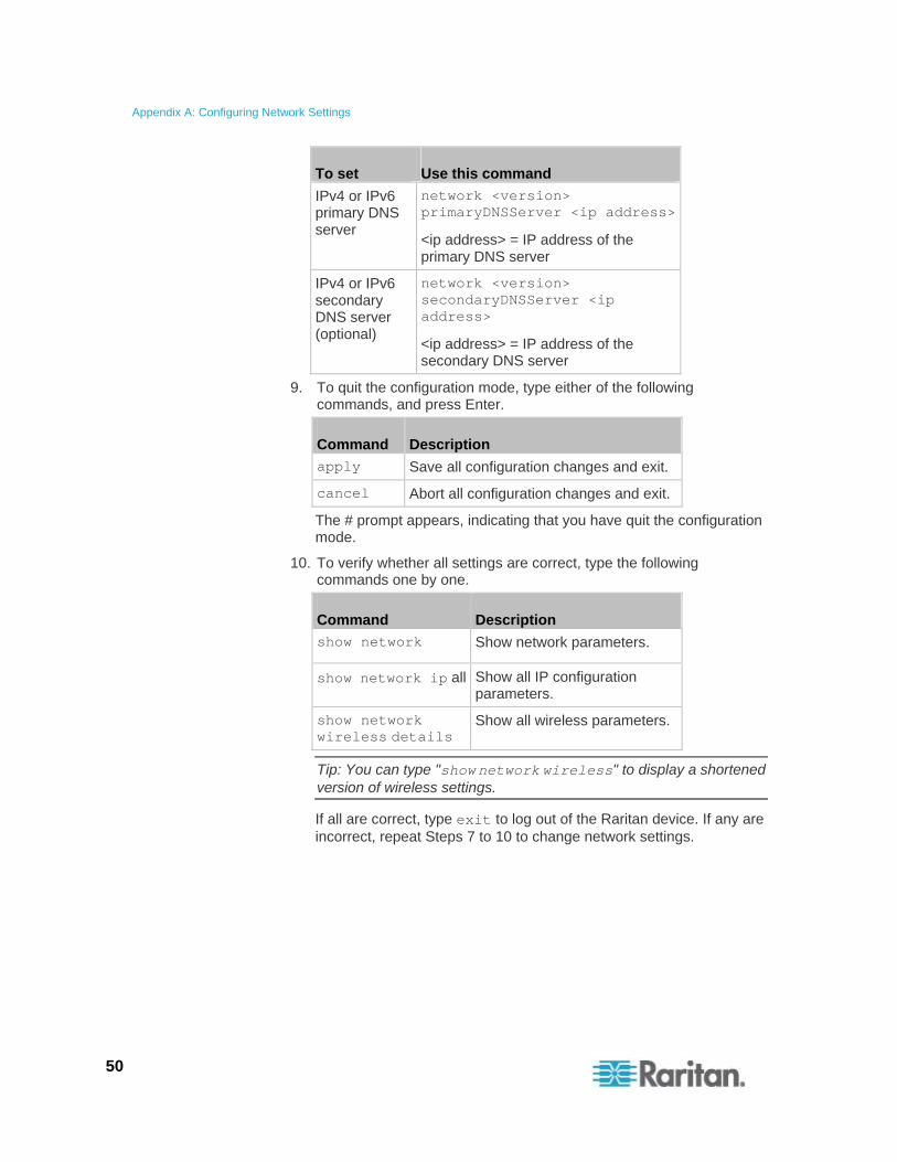
To set Use this command
IPv4 or IPv6 primary DNS server
network <version> primaryDNSServer <ip address>
<ip address> = IP address of the primary DNS server
IPv4 or IPv6 secondary DNS server (optional)
network <version> secondaryDNSServer <ip address>
<ip address> = IP address of the secondary DNS server
9. To quit the configuration mode, type either of the following commands, and press Enter.
Command Description
apply Save all configuration changes and exit.
cancel Abort all configuration changes and exit.
The # prompt appears, indicating that you have quit the configuration mode.
10. To verify whether all settings are correct, type the following commands one by one.
Command Description
show network Show network parameters.
show network ip all Show all IP configuration parameters.
show network wireless details
Show all wireless parameters.
Tip: You can type "show network wireless" to display a shortened version of wireless settings.
If all are correct, type exit to log out of the Raritan device. If any are incorrect, repeat Steps 7 to 10 to change network settings.
Accessibility Troubleshooting Appendix B
Any accessibility problem occurred on one of the devices in the USB-cascading configuration may result in failure to access all subsequent slave devices that are connected to it.
In This Chapter
Possible Root Causes .............................................................................51 Slave Connection and Disconnection Events..........................................52 The Ping Tool ..........................................................................................52
Possible Root Causes
The following lists the network accessibility issues and possible root causes.
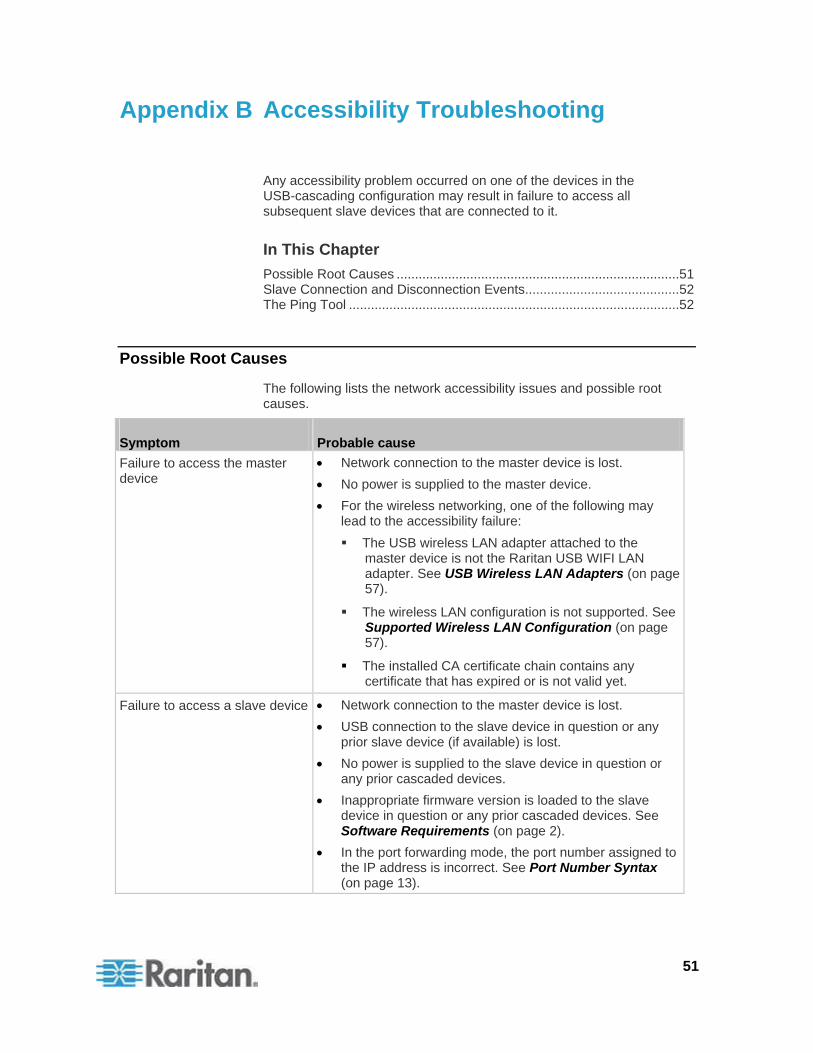
Symptom Probable cause
Failure to access the master device
Network connection to the master device is lost.
No power is supplied to the master device.
For the wireless networking, one of the following may lead to the accessibility failure:
The USB wireless LAN adapter attached to the master device is not the Raritan USB WIFI LAN adapter. See USB Wireless LAN Adapters (on page 57).
The wireless LAN configuration is not supported. See Supported Wireless LAN Configuration (on page 57).
The installed CA certificate chain contains any certificate that has expired or is not valid yet.
Failure to access a slave device Network connection to the master device is lost.
USB connection to the slave device in question or any prior slave device (if available) is lost.
No power is supplied to the slave device in question or any prior cascaded devices.
Inappropriate firmware version is loaded to the slave device in question or any prior cascaded devices. See Software Requirements (on page 2).
In the port forwarding mode, the port number assigned to the IP address is incorrect. See Port Number Syntax (on page 13).
51
Appendix B: Accessibility Troubleshooting
52
Tip: To determine which Raritan device may be the failure point of network, you may ping each Raritan device in the USB-cascading configuration, or look for the slave-related events in each Raritan device's event log. See Slave Connection and Disconnection Events (on page 52) and The Ping Tool (on page 52).
Slave Connection and Disconnection Events
Whenever the connection or disconnection of a subsequent slave device is detected, the Raritan device at the USB-A end of the USB cable logs it in the internal log. Note that the Raritan device at the USB-B end of the cable does NOT log these events.
There are two slave-related events:
Event Description
USB slave connected
This log entry is generated when a Raritan device detects the presence of a slave device on its USB-A port.
USB slave disconnected
This log entry is generated when it detects the disconnection of a slave device from its USB-A port.
The Ping Tool
The Raritan device provides a ping tool in the web interface and CLI so you can ping any host or Raritan device in your data center.
Using the Web Interface
To log in to the web interface, see HTTP/HTTPS Access (on page 22).
The Ping tool is useful for checking whether a host is accessible through the network or Internet.
To ping a host:
1. Choose Maintenance > Network Diagnostics > Ping. The Ping Network Host dialog appears.
2. In the Host Name field, type the name or IP address of the host that you want to check.
3. In the Number of Requests field, type a number up to 20 or adjust the value by clicking either arrow. This number determines how many packets are sent for pinging the host.
4. Click Run Ping to start pinging the host. A dialog appears, displaying the Ping results.
Appendix B: Accessibility Troubleshooting
53
5. Click Close to quit the dialog.
Using the CLI
You can access the CLI interface by connecting a computer to the Raritan device or using SSH/Telnet. See SSH/Telnet Access (on page 25) for details.
You must perform the ping command in the diagnostic mode. To enter the diagnostic mode, type the following command and press Ener.
# diag
After the diag> or diag# prompt appears, you can perform the ping command.
This ping command sends the ICMP ECHO_REQUEST message to a network host for checking its network connectivity. If the output shows the host is responding properly, the network connectivity is good. If not, either the host is shut down or it is not being properly connected to the network.
diag> ping <host>
Variables:
<host> is the host name or IP address whose networking connectivity you want to check.
Options:
You can include any or all of additional options listed below in the ping command.
Options Description
count <number1> Determines the number of messages to be sent. <number1> is an integer number between 1 and 100.
size <number2> Determines the packet size. <number2> is an integer number in bytes between 1 and 65468.
timeout <number3> Determines the waiting period before timeout. <number3> is an integer number in seconds ranging from 1 to 600.
The command looks like the following when it includes all options:
Appendix B: Accessibility Troubleshooting
54
diag> ping <host> count <number1> size <number2> timeout <number3>
Ethernet Disabled Scenarios on Slave Devices
Appendix C
The Ethernet interface is automatically disabled on slave devices. This appendix illustrates this limitation by showing two scenarios.
In This Chapter
Example 1................................................................................................55 Example 2................................................................................................56
Example 1
Raritan device-1 has been directly connected to the LAN. Its Ethernet interface is enabled and networking mode shows Wired.
Raritan device-2 has been directly connected to the LAN. Its Ethernet interface is enabled and networking mode shows Wired.
If now you connect Raritan device-1 to the USB-B port of Raritan device-2 using a USB cable, the following changes occur:
Raritan device-1 becomes the master device.
Raritan device-2 becomes a slave device.
The Ethernet interface on Raritan device-2 is automatically disabled. All of its IP packets are transmitted through Raritan device-1.
The networking mode of Raritan device-2 changes to Wired (USB), indicating that it is connected to the network through the master device.
55
Appendix C: Ethernet Disabled Scenarios on Slave Devices
56
Example 2
Raritan device-1 is a master device, which has Raritan device-2 connected to its USB-A port. On Raritan device-1, the Ethernet interface is enabled, and the networking mode shows Wired.
Raritan device-2 is a slave device, whose Ethernet interface has been disabled, networking mode shows Wired (USB), and IP packets are transmitted through the master device.
If you directly connect Raritan device-2 to the LAN now, NO changes occur.
Raritan device-2 continues to operate as a slave device.
The networking mode of Raritan device-2 still shows Wired (USB).
The Ethernet interface on Raritan device-2 remains disabled. All of its IP packets are still transmitted through the master device.
Wireless LAN Information Appendix D
The USB-cascading configuration supports either a wired or wireless LAN when in the port forwarding mode. See Setting the Cascading Mode (on page 11).
This appendix provides information regarding wireless LAN configuration and LAN adapters.
In This Chapter
Supported Wireless LAN Configuration...................................................57 USB Wireless LAN Adapters ...................................................................57
Supported Wireless LAN Configuration
If wireless networking is preferred, ensure that the wireless LAN configuration of your Raritan device matches the access point. The following is the wireless LAN configuration that the Raritan device supports.
Network type: 802.11 A/B/G/N
Protocol: WPA2 (RSN)
Key management: WPA-PSK, or WPA-EAP with PEAP and MSCHAPv2 authentication
Encryption: CCMP (AES)
Important: Supported 802.11 network protocols vary according to the wireless LAN adapter being used with the Raritan device. See USB Wireless LAN Adapters (on page 57).
USB Wireless LAN Adapters
A standalone Raritan device supports the use of all of the following USB wireless LAN adapters. However, the port forwarding mode only supports the use of the Raritan USB WIFI LAN adapter.
Wi-Fi LAN adapters Supported 802.11 protocols
Proxim Orinoco 8494 A/B/G
Zyxel NWD271N B/G
Edimax EW-7722UnD A/B/G/N
TP-Link TL-WDN3200 v1 A/B/G/N
57
Appendix D: Wireless LAN Information
58
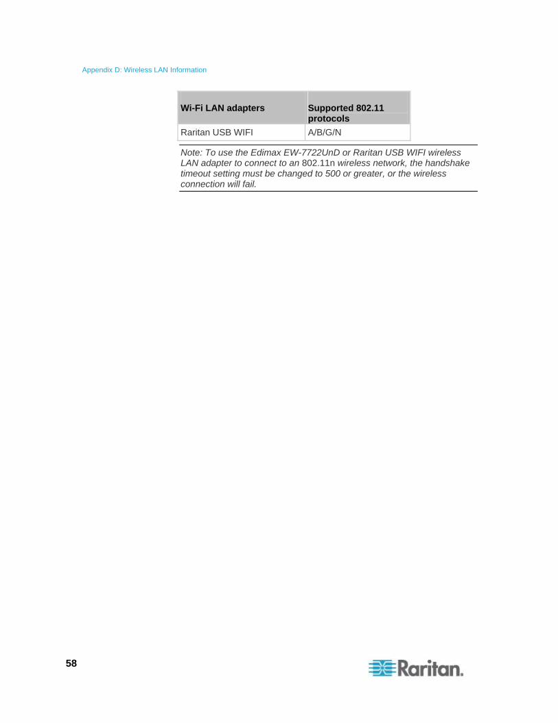
Wi-Fi LAN adapters Supported 802.11 protocols
Raritan USB WIFI A/B/G/N
Note: To use the Edimax EW-7722UnD or Raritan USB WIFI wireless LAN adapter to connect to an 802.11n wireless network, the handshake timeout setting must be changed to 500 or greater, or the wireless connection will fail.
Index
A
Accessibility Troubleshooting • 51 Appropriate Applications • 5
B
Best Practices • 7
C
Cascading the Raritan devices via USB • 1, 9, 22, 40
Character LCD Display • 21, 40 Configuration via CLI • 45 Configuration via Web Interface • 44 Configuring Network Settings • 44
D
Dot-Matrix LCD Display • 19, 38
E
Ethernet Disabled Scenarios on Slave Devices • 8, 55
Example 1 • 55 Example 2 • 56
F
Finding the IP Address • 17, 27
H
Hardware Requirements • 1, 9 HTTP/HTTPS Access • 22, 27, 52
I Identifying Cascaded Devices • 27 Inappropriate Applications • 7 Introduction • 1
L
LCD Display • 18 Local Console • 17
M
MAC Address • 18
N
Network Access • ix, 17
O
Overview of the Cascading Modes • ix, 2, 3, 11
P
Plug and Play • 4 Port Forwarding Examples • 12, 14, 25 Port Number Syntax • 4, 11, 13, 14, 51 Possible Root Causes • 51
S
Safety Guidelines • ii Safety Instructions • iii Setting the Cascading Mode • 3, 8, 9, 11, 14,
28, 39, 57 Slave Connection and Disconnection Events •
52 SNMP Management • 26 SNMP Notifications • 26 Software Requirements • ix, 2, 8, 10, 11, 27,
34, 36, 51 SSH/Telnet Access • 12, 25, 34, 53 Supported Web Browsers • 22, 23 Supported Wireless LAN Configuration • 51,
57
T
The Ping Tool • 52 Third-Party SNMP Managers • 26
U
Updating the Raritan device Firmware • 3, 9, 42
USB Wireless LAN Adapters • 9, 28, 51, 57 USB-Cascading Applications • 5 USB-Cascading Instructions • 8
59
Index
60
USB-Cascading Restrictions • 8 Using the CLI • 34, 53 Using the LCD Display • 38 Using the SNMP • 36 Using the Web Browser • 23 Using the Web Interface • 27, 52
W
What's New in the USB-Cascading Solution Guide • ix
Wireless LAN Information • 57
U.S./Canada/Latin America Monday - Friday 8 a.m. - 6 p.m. ET Phone: 800-724-8090 or 732-764-8886 For CommandCenter NOC: Press 6, then Press 1 For CommandCenter Secure Gateway: Press 6, then Press 2 Fax: 732-764-8887 Email for CommandCenter NOC: [email protected] Email for all other products: [email protected]
China
Beijing Monday - Friday 9 a.m. - 6 p.m. local time Phone: +86-10-88091890
Shanghai Monday - Friday 9 a.m. - 6 p.m. local time Phone: +86-21-5425-2499
GuangZhou Monday - Friday 9 a.m. - 6 p.m. local time Phone: +86-20-8755-5561
India Monday - Friday 9 a.m. - 6 p.m. local time Phone: +91-124-410-7881
Japan Monday - Friday 9:30 a.m. - 5:30 p.m. local time Phone: +81-3-5795-3170 Email: [email protected]
Europe
Europe Monday - Friday 8:30 a.m. - 5 p.m. GMT+1 CET Phone: +31-10-2844040 Email: [email protected]
United Kingdom Monday - Friday 8:30 a.m. to 5 p.m. GMT Phone +44(0)20-7090-1390
France Monday - Friday 8:30 a.m. - 5 p.m. GMT+1 CET Phone: +33-1-47-56-20-39
Germany Monday - Friday 8:30 a.m. - 5:30 p.m. GMT+1 CET Phone: +49-20-17-47-98-0 Email: [email protected]
Melbourne, Australia Monday - Friday 9:00 a.m. - 6 p.m. local time Phone: +61-3-9866-6887
Taiwan Monday - Friday 9 a.m. - 6 p.m. GMT -5 Standard -4 Daylight Phone: +886-2-8919-1333 Email: [email protected]