usb audio lass tutorial 1. introduction · peripheral and a host such as a pc. ... the host...
TRANSCRIPT

Rev. 0.1 6/06 Copyright © 2006 by Silicon Laboratories AN295
AN295
USB AUDIO CLASS TUTORIAL
1. Introduction
Isochronous data transfers can be used by universal serial bus (USB) devices designed to transfer data to or froma host at a constant rate. Systems streaming audio employ isochronous transfers to transmit audio signals in real-time. Silicon Laboratories microcontrollers’ robust USB peripheral supports isochronous transfers, and eachfamily’s assortment of additional high quality peripherals make them excellent single-chip solutions for USB-basedembedded system designs.
This document contains the following:
A USB protocol overview concentrating on isochronous transfers
A Firmware Template that provides a starting point for custom USB Audio Class device firmware
An example system illustrating requirements and operation of USB Audio Class devices
1.1. OverviewThe first section of this application note discusses the key points of the USB specification that must be followed byall USB devices, as well as isochronous transfer protocol requirements. The second section introduces theFirmware Template for USB Audio Class devices. The last section discusses an example USB Audio Class device.The example shows an Audio Class device that streams a sine wave to the host.
2. USB, Isochronous Transfers, and the Audio Class
The USB communications protocol outlines specifications for a reliable and fast system of data transfer between aperipheral and a host such as a PC. The protocol defines four different data transfer types (bulk, interrupt, control,and isochronous), each with unique characteristics and uses. USB device classes employ transfer types that suitthe needs of particular applications and systems. The USB Audio class uses the isochronous transfer type tostream audio across a USB link.
2.1. USB Operational OverviewWhen a USB device connects to a USB port, the host controlling the port retrieves information about thecapabilities of a device through control transfers during a process called enumeration. Devices format thisinformation into descriptors. USB Specification documents define the structure of descriptors.
USB devices send and receive data through endpoints. All USB devices must have one control endpoint throughwhich all enumeration data travels. Descriptors read during enumeration describe the device’s other endpoints,their data flow direction, maximum packet size, transfer type, and other characteristics used after enumerationsuccessfully completes.
After examining the device’s descriptors, the host determines how to communicate with the device. If the host canallocate resources (data bandwidth, power) requested by the device, then enumeration completes successfullyand the host begins operations communication with the device. During operations communications, transfermethods such as those using isochronous endpoint transfers take place.

AN295
2 Rev. 0.1
2.2. Isochronous Transfer CharacteristicsThe host guarantees bandwidth to isochronous endpoints. This bandwidth guarantee is a feature unique toisochronous endpoints. The amount of bandwidth allocated to a particular isochronous endpoint is determined byinformation requested by that endpoint’s descriptor. Data transfers take place inside USB data frames. For FullSpeed USB devices such as the Silicon Laboratories C8051F32x, a data frame spans 1 millisecond. A device canbe configured to transmit as few as 1 byte per frame or as many as 1023 bytes per frame.
The USB specification defines IN and OUT designations from the perspective of the host, meaning that INendpoints transmit data to the host and OUT endpoints receive data from the host. During every 1 millisecondinterval during communications operation, the host signals isochronous IN endpoints to transmit bytes to the host,and signals isochronous OUT endpoints to receive bytes from the host.
Unlike other transfer types, isochronous transfers have no hardware-controlled handshaking or error-checkingability, so errors may occur occasionally. Systems must be able to recover from occasional errors without the helpof hardware.
2.3. The USB Audio ClassThe USB Specification documents group devices with similar capabilities into device classes. Device Classspecifications require that devices share many characteristics in common, while allowing for customization andinnovation. The “Universal Serial Bus Device Class Definition for Audio Devices” describes how audio devicesmust perform, how class-specific Descriptors must be defined, etc. Because host operating systems typicallycontain device drivers for defined USB classes, designers of these devices do not need spend resources ondeveloping their own device drivers.
2.4. Creating an Audio Class Device With Silicon Laboratories MicrocontrollersThe creation of a USB Audio Class device requires two steps:
Descriptors retrieved by the host must be configured to describe a device as following the specifications for Audio Class devices.
Device firmware must configure the microcontroller to enable USB isochronous transfers.
The next section of this application note describes a Firmware Template that accomplishes the above two steps.The section following it provides an example of a USB Audio Class device.

AN295
Rev. 0.1 3
3. Firmware Template
The firmware template included with this application note allows users to create custom USB Audio Devices. Thetemplate contains all descriptors and routines needed to create a composite device with an audio interface and anHID interface.
The firmware template provides the following:
Descriptors defining a USB device with two Audio Interfaces, one for full bandwidth and an alternate zero bandwidth interface
Descriptors defining an HID interface with one IN endpoint, one OUT endpoint, and function stubs for Get Report and Set Report requests
Low-level USB routines to handle all standard requests and interrupts for the Audio class and the HID Class
The following subsections show how the Firmware Template can be modified to suit a custom audio streamingsystem.
3.1. DescriptorsOnly a few items in the descriptors contained in the Firmware Template will need to be changed to create a customsystem. Please read the section Tone Generator Reference Design for a more detailed explanation of theF320_USB_Descriptors.c file and how modifications to the descriptors affect the capabilities of the device.
The following is a checklist of descriptor items that may need to be modified in order to accurately describe thecharacteristics of a custom system:
The VID and PID items located in the Device Descriptor (these can be changed in F320_USB_Descriptor.h)
String index values (iProduct, iVendor, iInterface, etc.), depending on what strings the custom application defines
wTerminalType, which specifies type of Audio Class device defined by the descriptor (Terminal Type values can be found in the document titled “USB Device Class Definition for Terminal Types”)
bNrChannels, which commonly describes a stereo (2-channel) terminal or a mono (1-channel) terminal
wChannelConfig, which gives information on orientation of each channel (values can be found in the “USB Device Class Definition for Audio Devices”)
Master and channel controls, depending on what features the Audio Device supports (values can be found in the “USB Device Class Definition for Audio Devices”)
Audio Format Descriptor – the template contains a descriptor structure for a Type I format audio stream. Using other types of streams (defined in the document titled “USB Device Class Definition for Audio Data Formats”) may alter the size and structure of this descriptor)
Contents of the default Type I Audio Descriptor – these items describe the size of each sample, the sampling rate, etc. and must be changed to suit a custom system’s specifications
bEndpointAddress for the isochronous endpoint, depending on whether the custom application streams audio into the host or out of the host
HID Report Descriptor, depending on the system’s report structure requirements (see AN249 for a more detailed discussion)
The Report Descriptor’s size, stored as HID_REPORT_SIZE in F320_USB_Descriptor.h, to match the custom size of the Report Descriptor

AN295
4 Rev. 0.1
3.2. Endpoint 3 HandlerThe descriptors configure Endpoint 3 to be the Audio Class’s isochronous endpoint. The USB Interrupt ServiceRoutine ISR will vector to the Endpoint 3 handler when it receives a token packet from the host requesting atransfer with that endpoint. The contents of this handler are highly system specific, but will most likely perform oneor more of the following tasks:
For an IN stream from device to host, the handler places data on the Endpoint 3 FIFO.
For an OUT stream from host to device, the handler processes FIFO data received from the host.
The handler updates global variables used in other custom system-specific operations.
When large amounts of data must be processed inside the handler, fast ISR execution speed becomes crucial tosystem stability. If the device has not finished servicing one ISR call when the host calls for the device to begin thenext ISR call, audio packets might be lost. In these cases, users should consider writing code for the USB ISR andoften-executed routines in embedded 8051 assembler language. At slower data rates, such as the rate used in theTone Generator example, the handler can be written in C.
3.3. HID InterfaceFor communications across the HID Interface, users must make a number of modifications to Firmware Templatefiles. The HID Specification requires that all HID data be formatted into reports, which are data structures defined inone of the HID’s descriptors. Reports can travel across the control endpoint or the interrupt endpoints, Endpoint 1and Endpoint 2. The Firmware Template defines Endpoint 1 as an IN endpoint and Endpoint 2 as an OUT endpoint.The Control Endpoint sends and receives HID reports through the standard requests Set Report and Get Report,respectively.
Making the following modifications will enable HID data traffic:
In F3xx_USB_Common.c, write endpoint handler routines that process HID IN or OUT endpoint traffic
In F3xx_USB_Common.c, add calls to appropriate endpoint handlers in the USB Interrupt Service Routine.
In F3xx_USB_Class_Specific_Requests.c, Get_Report() contains a switch statement that need to be populated with a case for each potentially outgoing report, designated by its unique Report ID.
In F3xx_USB_Class_Specific_Requests.c, Set_Report() points data pointers to a buffer where incoming data is stored, and Handle_Set_Report() contains a switch statement that need to be populated with a case for each potentially incoming report.

AN295
Rev. 0.1 5
4. Tone Generator Reference Design
The Tone Generator reference design uses the Firmware Template to create a simple USB Audio Class Devicethat sends a single tone across an audio stream to a host-side PC application. This design generates its audiosignal by a wave table stored in the microcontroller’s nonvolatile memory. The system outputs a stereo sine waveacross an isochronous endpoint.
4.1. DescriptorsThe next subsections discuss how each of the descriptors of the firmware system defines the device as an AudioClass device with an isochronous endpoint. Table 1 gives a summary of each descriptor defined in the firmware.Indentations along the left side of the table indicate descriptors subordinate to descriptors listed before theindentation.
Table 1. Descriptor Summary
Device Descriptor Contains general information about the device that applies to all device configurations. A USB device can have only one Device Descriptor
Configuration Descriptor Describes a collection of interfaces (paths for data traffic). Call to retrieve this descriptor returns all subordinate descriptors (as seen below). This configuration contains 4 interfaces.
Audio Control Interface Descriptor Describes audio interface from perspective of data paths and controls. Subordinate descriptors follow.
Interface Header Audio Class Descriptor Lists the different data paths (terminals) and their capabilities (units).
Input Terminal Audio Class Descriptor Describes audio control data traveling from host to device.
Feature Unit Audio Class Descriptor Lists controls (volume, muting, etc.) associated with the above terminal.
Output Terminal Audio Class Descriptor Describes the audio data traveling out of the device and into the host.
Audio Stream Interface Descriptor Describes the audio stream that uses an isochronous endpoint to transfer the audio.
Alternate Audio Interface Descriptor Required alternate interface that does not use the isochronous endpoint. This interface is chosen by the host when lack of band-width prevents the use of the isochronous endpoint.
Audio Stream Audio Class Descriptor Describes the audio stream type in greater detail.
Format Type Audio Descriptor Gives specific specifications of audio stream.
Isochronous Endpoint Descriptor Assigns an endpoint to be the audio stream’s isochronous end-point.
Isochronous Endpoint Audio Class Descriptor
Gives Audio Class-specific characteristics of the isochronous endpoint.
HID Interface Descriptor Defines the HID interface.
HID Descriptor Describes the capabilities of the HID interface.
HID IN Endpoint Descriptor Assigns an endpoint to be an IN interrupt endpoint used by the HID interface.
HID OUT Endpoint Descriptor Assigns an endpoint to be an OUT interrupt endpoint used by the HID interface.
Report Descriptor Defines all HID data structures.
AN295
6 Rev. 0.1
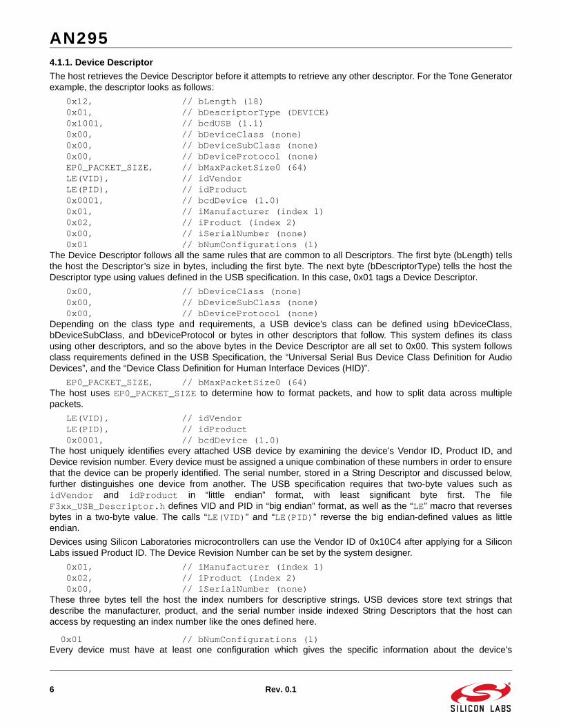
4.1.1. Device Descriptor
The host retrieves the Device Descriptor before it attempts to retrieve any other descriptor. For the Tone Generatorexample, the descriptor looks as follows:
0x12, // bLength (18) 0x01, // bDescriptorType (DEVICE) 0x1001, // bcdUSB (1.1) 0x00, // bDeviceClass (none) 0x00, // bDeviceSubClass (none) 0x00, // bDeviceProtocol (none) EP0_PACKET_SIZE, // bMaxPacketSize0 (64) LE(VID), // idVendor LE(PID), // idProduct 0x0001, // bcdDevice (1.0) 0x01, // iManufacturer (index 1) 0x02, // iProduct (index 2) 0x00, // iSerialNumber (none) 0x01 // bNumConfigurations (1)The Device Descriptor follows all the same rules that are common to all Descriptors. The first byte (bLength) tellsthe host the Descriptor’s size in bytes, including the first byte. The next byte (bDescriptorType) tells the host theDescriptor type using values defined in the USB specification. In this case, 0x01 tags a Device Descriptor.
0x00, // bDeviceClass (none) 0x00, // bDeviceSubClass (none) 0x00, // bDeviceProtocol (none)Depending on the class type and requirements, a USB device’s class can be defined using bDeviceClass,bDeviceSubClass, and bDeviceProtocol or bytes in other descriptors that follow. This system defines its classusing other descriptors, and so the above bytes in the Device Descriptor are all set to 0x00. This system followsclass requirements defined in the USB Specification, the “Universal Serial Bus Device Class Definition for AudioDevices”, and the “Device Class Definition for Human Interface Devices (HID)”.
EP0_PACKET_SIZE, // bMaxPacketSize0 (64)The host uses EP0_PACKET_SIZE to determine how to format packets, and how to split data across multiplepackets.
LE(VID), // idVendor LE(PID), // idProduct 0x0001, // bcdDevice (1.0)The host uniquely identifies every attached USB device by examining the device’s Vendor ID, Product ID, andDevice revision number. Every device must be assigned a unique combination of these numbers in order to ensurethat the device can be properly identified. The serial number, stored in a String Descriptor and discussed below,further distinguishes one device from another. The USB specification requires that two-byte values such asidVendor and idProduct in “little endian” format, with least significant byte first. The fileF3xx_USB_Descriptor.h defines VID and PID in “big endian” format, as well as the “LE” macro that reversesbytes in a two-byte value. The calls “LE(VID)” and “LE(PID)” reverse the big endian-defined values as littleendian.
Devices using Silicon Laboratories microcontrollers can use the Vendor ID of 0x10C4 after applying for a SiliconLabs issued Product ID. The Device Revision Number can be set by the system designer.
0x01, // iManufacturer (index 1) 0x02, // iProduct (index 2) 0x00, // iSerialNumber (none)These three bytes tell the host the index numbers for descriptive strings. USB devices store text strings thatdescribe the manufacturer, product, and the serial number inside indexed String Descriptors that the host canaccess by requesting an index number like the ones defined here.
0x01 // bNumConfigurations (1)Every device must have at least one configuration which gives the specific information about the device’s

AN295
Rev. 0.1 7
capabilities. Each configuration will have at least one associated descriptor.
4.1.2. Configuration Descriptor
This Descriptor gives the host information about the device’s capabilities. Configuration Descriptors havesubordinate descriptors that further describe the device.
The Tone Generator’s firmware defines the Configuration Descriptor:
0x09, // bLength (9) 0x02, // bDescriptorType (CONFIGURATION) 0x9100, // wTotallength (145) 0x03, // bNumInterfaces (3) 0x01, // bConfigurationValue (1) 0x00, // iConfiguration (none) 0x80, // bmAttributes (bus-powered) 0x32, // bMaxPower (100 mA)
0x03, // bNumInterfaces (3)bNumInterfaces tells the host how many interfaces the device uses. An interface is a point of contact where thehost and the device exchange data. The Tone Generator uses a total of four interfaces, but only three will be activeat any one time.
0x01, // bConfigurationValue (1)0x00, // iConfiguration (none)
These bytes tag the configuration described by this Configuration Descriptor and subordinate descriptors as ‘0x01’.The host issues a standard request to the device called Set Configuration using the value ‘0x01’ to commandthe device to use this particular configuration. The byte iConfiguration gives the index value for a stringdescribing the Configuration.
4.1.3. Interface Descriptor
After the device sends a Configuration Descriptor, it transfers one or more Interface Descriptors, each of whichdescribe one or more interfaces of that configuration, along with each interface’s subordinate descriptors. The ToneGenerator firmware contains four Interface Descriptors, one for each of the following interfaces:
The Audio Control interface used to transfer commands governing the audio stream
An interface for the audio’s streaming isochronous endpoint
An alternate interface that requires no bandwidth for the audio stream
An HID interface that describes the IN and OUT HID endpoints (not used in this example)
The firmware defines the standard Interface Descriptor for the Audio Control interface as follows:
0x09, // bLength (9) 0x04, // bDescriptorType (INTERFACE) 0x00, // bInterfaceNumber (0) 0x00, // bAlternateSetting (none) 0x00, // bNumEndpoints (none) 0x01, // bInterfaceClass (AUDIO) 0x01, // bInterfaceSubClass (AUDIO_CONTROL) 0x00, // bInterfaceProtocol (none) 0x00 // iInterface (none)
0x00, // bInterfaceNumber (0) 0x00, // bAlternateSetting (none)The host can use the values in these bytes to switch between composite or mutually exclusive interfaces. Sincethis particular interface does not require this operation, the values are set to 0.
0x00, // bNumEndpoints (none)USB Specification states that the number of endpoints listed in this field of the standard Interface Descriptor for anAudio Control device should be set to 0 unless the device uses an optional interrupt status endpoint.

AN295
8 Rev. 0.1
0x01, // bInterfaceClass (AUDIO) 0x01, // bInterfaceSubClass (AUDIO_CONTROL)These bytes use values set by the USB Specification to define a standard Audio interface, with a subclass set toAudio Control.
0x00, // bInterfaceProtocol (none)The byte used in this field must be set to ‘0x00’ or set to a defined value found in the USB Specification. The field isnot used in this system.
4.1.4. Interface Header Audio Class Descriptor
Following the USB standard Interface Descriptor for the Audio Control interface is a group of class-specificdescriptors that detail the capabilities of the Audio Control, including every function, terminal, and unit. A function isa data port, and a unit is a control on that data port. In these descriptors, the term “input” describes informationflowing into the interface, such as control commands sent from the host. “Output” describes information flowing outof the interface, such as the audio streaming from the generated tone.
The first descriptor in the group is a class-specific Interface Header Descriptor, as follows:
0x09, // bLength (9) 0x24, // bDescriptorType (CS_INTERFACE) 0x01, // bDescriptorSubtype (HEADER) 0x0001, // bcdADC (1.0) 0x2B00, // wTotalLength (43) 0x01, // bInCollection (1 streaming interface) 0x01 // baInterfaceNr (interface 1 is stream)
0x24, // bDescriptorType (CS_INTERFACE) 0x01, // bDescriptorSubtype (HEADER)These bytes designate the descriptor as a class-specific Header Descriptor. Descriptors that follow will use thesame CS_INTERFACE Descriptor type with different sub-types to distinguish each descriptor.
0x0001, // bcdADC (1.0)This two-byte value tells the host which revision of the Audio Class specification the device follows.
0x2B00, // wTotalLength (43)This field gives the total size of all Descriptors in this class-specific Interface group that follow.
0x01, // bInCollection (1 streaming interface)This field describes how many audio streams this Audio Control Interface controls. This system uses one stream,which is the isochronous endpoint that carries the audio signal from the microcontroller to the host application.
0x01 // baInterfaceNr (interface 1 is stream)This field tells the host the name of the audio stream interface that is controlled by this Audio Control interface. In aDescriptor following this one, the audio stream’s interface will be given the name ‘0x01’.

AN295
Rev. 0.1 9
4.1.5. Input Terminal Audio Class Descriptor
The next Descriptor, using the subclass tag Input Terminal, describes capabilities of the controls on the audiostream.
0x0C, // bLength (12) 0x24, // bDescriptorType (CS_INTERFACE) 0x02, // bDescriptorSubtype (INPUT_TERMINAL) 0x01, // bTerminalID (1) 0x1007, // wTerminalType (radio receiver) 0x00, // bAssocTerminal (none) 0x02, // bNrChannels (2) 0x0300, // wChannelConfig (left, right) 0x00, // iChannelNames (none) 0x00 // iTerminal (none)
0x01, // bTerminalID (1)The host addresses this terminal using the value stored in this ID field.
0x1007, // wTerminalType (radio receiver)This two-byte value defines the input terminal’s control according to definitions found in the document called “USBAudio Terminal Types”.
0x00, // bAssocTerminal (none)Some terminals are associated with other terminals. For example, an input terminal could be a microphone, and itsassociated output terminal could be the headset attached to that microphone. This example has only one inputterminal for the audio stream and no associated terminals.
0x02, // bNrChannels (2) 0x0300, // wChannelConfig (left, right)These fields describe the number of “logical” channels in the audio channel cluster, and the spatial characteristicsof the audio channels. This stream will carry a stereo signal, with a left and a right channel of audio.
0x00, // iChannelNames (none) 0x00 // iTerminal (none)These fields are indexes to strings describing the name of the first logical audio channel of the stream and thename of the terminal, respectively. This example does not define these strings.
4.1.6. Feature Unit Audio Class Descriptor
The next Descriptor describes the capabilities of a Feature Unit associated with the input terminal. A Feature unitcan control different aspects of an audio stream such as volume control, audio gain, and delay. The firmwaredefines the Feature Unit as follows:
0x0D, // bLength (13) 0x24, // bDescriptorType (CS_INTERFACE) 0x06, // bDescriptorSubtype (FEATURE_UNIT) 0x02, // bUnitID (2) 0x01, // bSourceID (input terminal 1) 0x02, // bControlSize (2 bytes) 0x0100, // Master controls 0x0000, // Channel 0 controls 0x0000, // Channel 1 controls 0x00 // iFeature (none)
0x02, // bUnitID (2)bUnitID gives the unit a unique ID, and this value is chosen by the programmer.
0x01, // bSourceID (input terminal 1)bSourceID associates the feature unit with the input terminal.
0x02, // bControlSize (2 bytes)

AN295
10 Rev. 0.1
bControlSize tells the host how many controls the feature unit includes. The number is actually an array sizethat describes the number of two-byte elements that follows. In this project, the Feature Unit has a Master Controlat index 0, control for the left channel on index 1, and control for the right channel at index 2 in the array thatimmediately follows.
0x0100, // Master controls 0x0000, // Channel 0 controls (LEFT) 0x0000, // Channel 1 controls (RIGHT)Each two-byte value is a bit map where each bit is defined in the Audio Class Specification. Bits correspond toFeature Unit functionality such as volume control, bass, treble, and mid levels, etc. This project supports the “mute”control on the master channel. The master controls apply to every channel of the associated terminal.
4.1.7. Output Terminal Audio Class Descriptor
The next Descriptor tells the host about the capabilities of the Interface’s output terminal, which will contains theaudio stream. The firmware defines the output terminal’s Descriptor as follows:
0x09, // bLength (9) 0x24, // bDescriptorType (CS_INTERFACE) 0x03, // bDescriptorSubtype (OUTPUT_TERMINAL) 0x03, // bTerminalID (3) 0x0101, // wTerminalType (USB streaming) 0x00, // bAssocTerminal (none) 0x02, // bSourceID (feature unit 2) 0x00 // iTerminal (none)
0x03, // bTerminalID (3)The value bTerminalID gives the output terminal a unique ID, chosen by the programmer.
0x0101, // wTerminalType (USB streaming)wTerminalType defines the terminal’s stream according to definitions found in the document called “USB AudioTerminal Types”.
0x00, // bAssocTerminal (none)This terminal is not associated with any other terminals.
0x02, // bSourceID (feature unit 2)This value establishes a connection between the output terminal and the feature unit defined in a previousdescriptor.
4.1.8. Audio Interface Descriptor
The next two descriptors define the audio streaming interface for the Tone Generator, which will contain theisochronous endpoint. USB Specification requires that interfaces with an isochronous endpoint must also define analternative interface without that isochronous endpoint. The specification imposes this requirement so that a devicecan successfully enumerate even if the host cannot allocate the data bandwidth required by the isochronousendpoint.
The firmware defines the first standard Interface Descriptor for the audio stream as follows:
0x09, // bLength (9) 0x04, // bDescriptorType (INTERFACE) 0x01, // bInterfaceNumber (1) 0x00, // bAlternateSetting (0) 0x00, // bNumEndpoints (0) 0x01, // bInterfaceClass (AUDIO) 0x02, // bInterfaceSubClass (AUDIO_STREAMING) 0x00, // bInterfaceProtocol (none) 0x00 // iInterface (none)
0x01, // bInterfaceNumber (1) 0x00, // bAlternateSetting (0)
AN295
Rev. 0.1 11
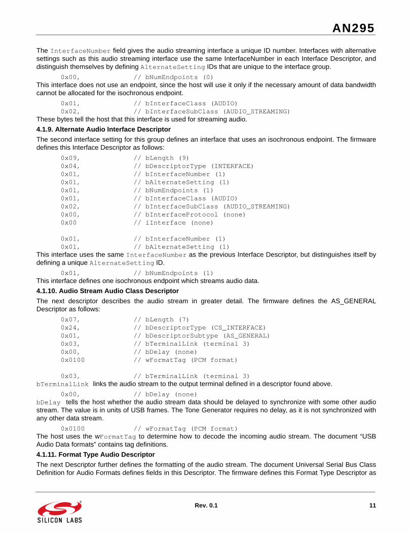
The InterfaceNumber field gives the audio streaming interface a unique ID number. Interfaces with alternativesettings such as this audio streaming interface use the same InterfaceNumber in each Interface Descriptor, anddistinguish themselves by defining AlternateSetting IDs that are unique to the interface group.
0x00, // bNumEndpoints (0)This interface does not use an endpoint, since the host will use it only if the necessary amount of data bandwidthcannot be allocated for the isochronous endpoint.
0x01, // bInterfaceClass (AUDIO) 0x02, // bInterfaceSubClass (AUDIO_STREAMING)These bytes tell the host that this interface is used for streaming audio.
4.1.9. Alternate Audio Interface Descriptor
The second interface setting for this group defines an interface that uses an isochronous endpoint. The firmwaredefines this Interface Descriptor as follows:
0x09, // bLength (9) 0x04, // bDescriptorType (INTERFACE) 0x01, // bInterfaceNumber (1) 0x01, // bAlternateSetting (1) 0x01, // bNumEndpoints (1) 0x01, // bInterfaceClass (AUDIO) 0x02, // bInterfaceSubClass (AUDIO_STREAMING) 0x00, // bInterfaceProtocol (none) 0x00 // iInterface (none)
0x01, // bInterfaceNumber (1) 0x01, // bAlternateSetting (1)This interface uses the same InterfaceNumber as the previous Interface Descriptor, but distinguishes itself bydefining a unique AlternateSetting ID.
0x01, // bNumEndpoints (1)This interface defines one isochronous endpoint which streams audio data.
4.1.10. Audio Stream Audio Class Descriptor
The next descriptor describes the audio stream in greater detail. The firmware defines the AS_GENERALDescriptor as follows:
0x07, // bLength (7) 0x24, // bDescriptorType (CS_INTERFACE) 0x01, // bDescriptorSubtype (AS_GENERAL) 0x03, // bTerminalLink (terminal 3) 0x00, // bDelay (none) 0x0100 // wFormatTag (PCM format)
0x03, // bTerminalLink (terminal 3)bTerminalLink links the audio stream to the output terminal defined in a descriptor found above.
0x00, // bDelay (none)bDelay tells the host whether the audio stream data should be delayed to synchronize with some other audiostream. The value is in units of USB frames. The Tone Generator requires no delay, as it is not synchronized withany other data stream.
0x0100 // wFormatTag (PCM format)The host uses the wFormatTag to determine how to decode the incoming audio stream. The document “USBAudio Data formats” contains tag definitions.
4.1.11. Format Type Audio Descriptor
The next Descriptor further defines the formatting of the audio stream. The document Universal Serial Bus ClassDefinition for Audio Formats defines fields in this Descriptor. The firmware defines this Format Type Descriptor as
AN295
12 Rev. 0.1
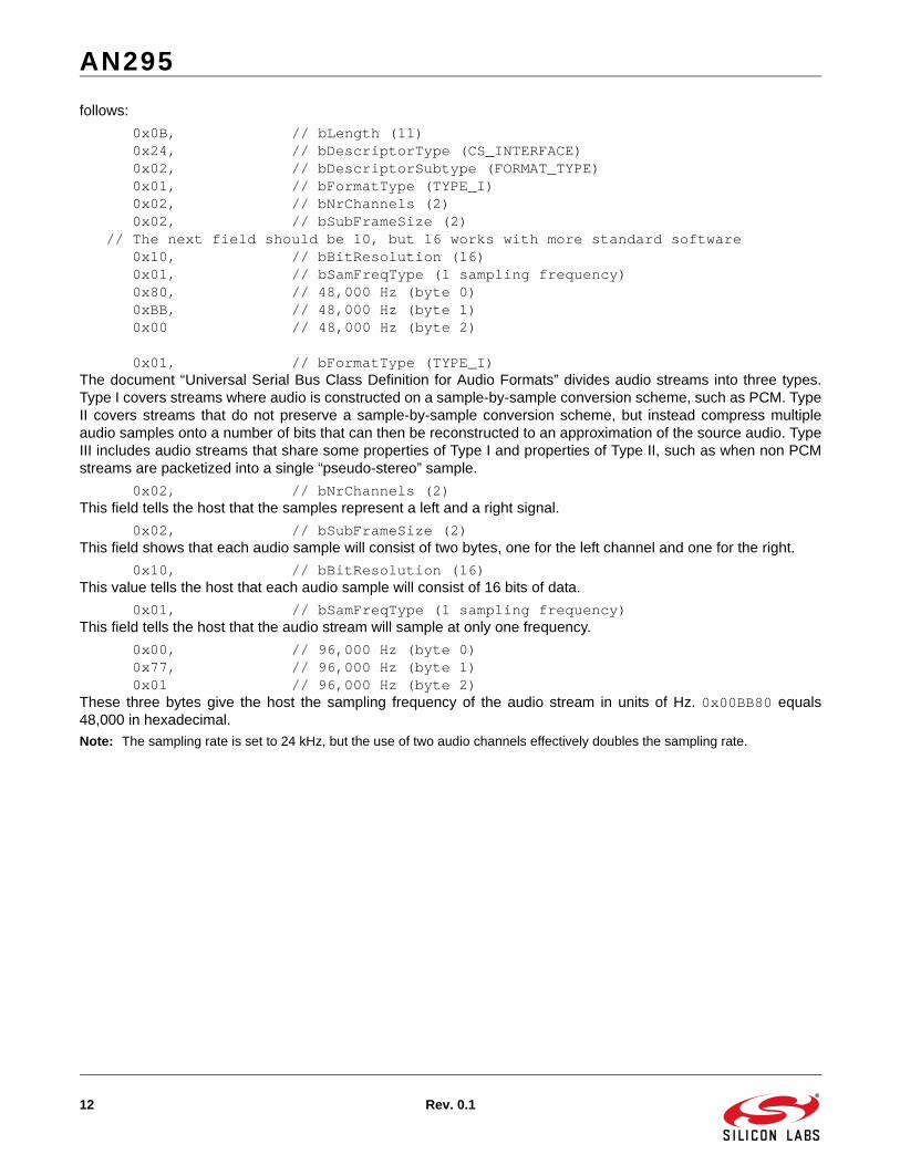
follows:
0x0B, // bLength (11) 0x24, // bDescriptorType (CS_INTERFACE) 0x02, // bDescriptorSubtype (FORMAT_TYPE) 0x01, // bFormatType (TYPE_I) 0x02, // bNrChannels (2) 0x02, // bSubFrameSize (2) // The next field should be 10, but 16 works with more standard software 0x10, // bBitResolution (16) 0x01, // bSamFreqType (1 sampling frequency) 0x80, // 48,000 Hz (byte 0) 0xBB, // 48,000 Hz (byte 1) 0x00 // 48,000 Hz (byte 2)
0x01, // bFormatType (TYPE_I)The document “Universal Serial Bus Class Definition for Audio Formats” divides audio streams into three types.Type I covers streams where audio is constructed on a sample-by-sample conversion scheme, such as PCM. TypeII covers streams that do not preserve a sample-by-sample conversion scheme, but instead compress multipleaudio samples onto a number of bits that can then be reconstructed to an approximation of the source audio. TypeIII includes audio streams that share some properties of Type I and properties of Type II, such as when non PCMstreams are packetized into a single “pseudo-stereo” sample.
0x02, // bNrChannels (2)This field tells the host that the samples represent a left and a right signal.
0x02, // bSubFrameSize (2)This field shows that each audio sample will consist of two bytes, one for the left channel and one for the right.
0x10, // bBitResolution (16)This value tells the host that each audio sample will consist of 16 bits of data.
0x01, // bSamFreqType (1 sampling frequency)This field tells the host that the audio stream will sample at only one frequency.
0x00, // 96,000 Hz (byte 0) 0x77, // 96,000 Hz (byte 1) 0x01 // 96,000 Hz (byte 2)These three bytes give the host the sampling frequency of the audio stream in units of Hz. 0x00BB80 equals48,000 in hexadecimal.
Note: The sampling rate is set to 24 kHz, but the use of two audio channels effectively doubles the sampling rate.

AN295
Rev. 0.1 13
4.1.12. Isochronous Endpoint Descriptor
The next descriptor defines the isochronous endpoint for the Tone Generator. The firmware reads as follows:
0x09, // bLength (9) 0x05, // bDescriptorType (ENDPOINT) 0x83, // bEndpointAddress (EP3 in) 0x05, // bmAttributes (asynchronous) 0x0002, // wMaxPacketSize (512) 0x01, // bInterval (1 millisecond) 0x00, // bRefresh (0) 0x00 // bSynchAddress (no synchronization)
0x05, // bDescriptorType (ENDPOINT)This value is the standard descriptor type for an endpoint descriptor.
0x83, // bEndpointAddress (EP3 in)This field tells the host that endpoint three is configured to be an IN endpoint.
0x05, // bmAttributes (asynchronous)This field sets the endpoint to be asynchronous and isochronous. Isochronous endpoints can operate in threedifferent modes: asynchronous, where the stream uses a clock independent from the USB clock source;synchronous, where the stream’s clock source is linked to the USB’s clock, such as through the use of USBframes; and adaptive, where the stream’s clock source varies according to the buffer requirements of the stream.
0x0002, // wMaxPacketSize (512)This two-byte field tells the host that the maximum packet size is 0x0200, or 512 bytes.
0x01, // bInterval (1 millisecond)This field tells the host that the isochronous endpoint requires one packet per 1 millisecond USB frame.
0x00, // bRefresh (0) 0x00 // bSynchAddress (no synchronization)These two bytes are not used by this example system.
0x83, // bEndpointAddress (EP3 in) 0x05, // bmAttributes (asynchronous)These two bytes set Endpoint 3 to be asynchronous, isochronous, and input. The endpoint is set to asynchronousbecause the Tone Generator outputs samples independently of a USB-driven clock source.
0x0002, // wMaxPacketSize (512) 0x01, // bInterval (1 millisecond)These two bytes show the bandwidth requirements for the endpoint. In this case, the endpoint requires enoughdata bandwidth to transmit up to 512 bytes every 1 millisecond.
0x00, // bRefresh (0) 0x00 // bSynchAddress (no synchronization)These two bytes are only used when the endpoint provides synchronization data for the system. Since thisendpoint is asynchronous, these bytes must be set to ‘0x00’.
4.1.13. Isochronous Endpoint Audio Class Descriptor
The Descriptor following the standard Endpoint Descriptor is the class-specific Endpoint Descriptor. The firmwaredefines this Descriptor as follows:
0x07, // bLength (7) 0x25, // bDescriptorType (CS_ENDPOINT) 0x01, // bDescriptorSubtype (EP_GENERAL) 0x00, // bmAttributes (none) 0x02, // bLockDelayUnits (PCM samples) 0x0000 // wLockDelay (0)
0x00, // bmAttributes (none)

AN295
14 Rev. 0.1
This byte tells the host whether the endpoint supports adaptive audio pitch control, adaptive sampling frequency,and whether the endpoint supports packets of maximum packet size only. Setting this byte to zero shows that thisendpoint supports none of those features or requirements.
0x02, // bLockDelayUnits (PCM samples) 0x0000 // wLockDelay (0)These three bytes are used mainly by synchronous endpoints to tell the host how long the device will take to lockonto the synchronized clock source and provide a data stream. LockDelayUnits has a reserved value for PCMsample streams, which this firmware uses. For asynchronous streams, the two-byte LockDelay should be set to0x00.
4.1.14. HID Interface Descriptor
The next Descriptors define the HID interface, which the system uses to pass control information to and from thehost’s application. The firmware defines the standard Interface Descriptor for the HID interface as follows:
0x09, // bLength (9) 0x04, // bDescriptorType (INTERFACE) 0x02, // bInterfaceNumber (2) 0x00, // bAlternateSetting (0) 0x02, // bNumEndpoints (2) 0x03, // bInterfaceClass (HID) 0x00, // bInterfaceSubClass (none) 0x00, // bInterfaceProtocol (none) 0x00 // iInterface (none)
0x02, // bInterfaceNumber (2) 0x00, // bAlternateSetting (0)These values give the interface a unique ID. Unlike the Audio Stream interface, the firmware defines only oneversion of the HID Interface, so no AlternateSetting codes need be defined.
0x02, // bNumEndpoints (2)This interface uses two endpoints, one IN and one OUT.
0x03, // bInterfaceClass (HID)This value is defined in the document titled “Device Class Definition for HID”.
0x00, // bInterfaceSubClass (none) 0x00, // bInterfaceProtocol (none)For an HID class device, these values are undefined and should be set to 0x00.
Next, the firmware defines the HID Descriptor, which follows a format shown in the document titled “Device ClassDefinition for HID”. The firmware defines the Descriptor as follows:
0x09, // bLength (9) 0x21, // bDescriptorType (HID_DESCRIPTOR) 0x1101, // bcdHID (1.11) 0x00, // bCountryCode (none) 0x01, // bNumDescriptors (1 class Descriptor) 0x22, // bClassDescriptorType (report descr.) LE(HID_REPORT_SIZE)// wDescriptorLength (203)
0x1101, // bcdHID (1.11)This BCD-encoded value tells the host which version of the HID specification the device follows. This systemfollows HID specifications defined in revision 1.11.
0x00, // bCountryCode (none)This field can be left blank, or it can be set to a value defining the country to which the device’s firmware has beenlocalized. This system, like most, has not been localized to function in a certain country.
0x01, // bNumDescriptors (1 class Descriptor)This value tells the host that the HID Descriptor has one subordinate descriptor. All HID descriptors have at least a

AN295
Rev. 0.1 15
Report Descriptor which defines report sizes and data types.
0x22, // bClassDescriptorType (report descr.) LE(HID_REPORT_SIZE)// wDescriptorLength (203)This section of the descriptor allows the firmware to describe the type and size of each subordinate descriptor.
4.1.15. HID IN Endpoint Descriptor
The next two descriptors define HID’s endpoints. The firmware defines the IN endpoint as follows:
0x07, // bLength (7) 0x05, // bDescriptorType (ENDPOINT) 0x81, // bEndpointAddress (EP1 in) 0x03, // bmAttributes (interrupt) 0x4000, // wMaxPacketSize (64) 0x0A // bInterval (10 milliseconds)
0x81, // bEndpointAddress (EP1 in)This value sets Endpoint 1 to be IN.
0x03, // bmAttributes (interrupt)This value configures the endpoint to be of type Interrupt.
0x4000, // wMaxPacketSize (64)These two bytes define the maximum packet size for the endpoint.
0x0A // bInterval (10 milliseconds)This byte tells the host to send a token packet to the device requesting an IN packet once every 10 milliseconds.
4.1.16. HID OUT Endpoint Descriptor
The firmware defines HID’s OUT endpoint as follows:
0x07, // bLength (7) 0x05, // bDescriptorType (ENDPOINT) 0x02, // bEndpointAddress (EP2 out) 0x03, // bmAttributes (interrupt) 0x4000, // wMaxPacketSize (64) 0x01 // bInterval (1 millisecond)
0x02, // bEndpointAddress (EP2 out)This value sets Endpoint 2 to be an OUT endpoint.
0x03, // bmAttributes (interrupt)As was seen in the previous descriptor, this value tells the host that the endpoint is of type Interrupt.
0x01 // bInterval (1 millisecond)This value tells the host that the device expects to see an OUT packet once every millisecond.
4.1.17. Report Descriptor
The HID interface defines exactly how data is formatted using a Report Descriptor. The Report Descriptor defineseach report using a template shown here:
0x85, 0x__, // REPORT_ID (__) 0x75, 0x__, // REPORT_COUNT (__) 0x95, 0x__, // REPORT_SIZE (__) 0x09, 0x01, // USAGE (Vendor Usage 1) 0xB1, 0x__, // INPUT/OUTPUT/FEATURE (Data,Var,Abs)
0x85, 0x__, // REPORT_ID (__)These two bytes define the Report’s ID. During operations communication, the host requests or transmits reportsusing this unique Report ID.
0x75, 0x__, // REPORT_COUNT (__) 0x95, 0x__, // REPORT_SIZE (__)

AN295
16 Rev. 0.1
These two values define report data type. REPORT_COUNT indicates how many data items the report contains, andREPORT_SIZE indicates the size of each data item in terms of bits. The buffer size of the report, in units of bits, canbe found by multiplying REPORT_COUNT and REPORT_SIZE. A report's buffer size can be as large as the HIDendpoint’s maximum size, which is set in the Endpoint Descriptor.
0x09, 0x01, // USAGE (Vendor Usage 1)This value gives the host information about how to process the data contained in the Report. In this case, the datais tagged as vendor defined, and so the host system assumes that a user-level application will process the data.
0xB1/0x91, 0x02, // FEATURE/OUTPUT (Data,Var,Abs) This value is set to ‘0x91’ for output reports and 0xB1 for feature reports. Output reports travel from host to device,and feature reports can travel from either host to device or device to host.
4.2. Endpoint 3 HandlerFigure 1 shows the path that data travels from the device to the host system.
The isochronous endpoint handler, located in the file F320_ToneGenerator.c, takes samples from the 256-elementsine wave table and writes them to the Endpoint 3 buffer. The handler writes samples to the buffer inside a loopwith the following termination condition::
(FIFO_INDEX < (48*4))The host requests a packet from the isochronous endpoint every USB frame, which occurs once every millisecond.For 48,000 samples to be transmitted every second, 48 samples must be transmitted every 1-millisecond frame.Every sample requires four bytes, as the left and right channel each require two bytes for their 16-bit values. Apointer to the sine wave table increments with every loop iteration and wraps around to the first element of the tableat the start of every period of sine wave output.
Figure 1. Data Path
Sine wave stored as 256-element
wave table
Host sends
token IN packet to
device
Device calls IN packet
Handler
IN packet Handler moves audio data from
table to USB endpoint buffer
Device transmits buffer to
Host
DeviceHost

AN295
Rev. 0.1 17
4.3. Host ApplicationThe host application connects to the device and streams the audio signal through WAV output functions. When auser presses the “connect” button on-screen, the function OpenDevice() searches through the list of attachedAudio Class USB devices and creates a handle for the Tone Generator device if the function finds it. After theapplication finds the device, it begins to periodically call the AudioStream() function, which manages the audiodata stream by placing received bytes from the stream onto a circular buffer, then removing bytes from that bufferand sending them out to a sound device.

http://www.silabs.com
Silicon Laboratories Inc.400 West Cesar ChavezAustin, TX 78701USA
Simplicity Studio
One-click access to MCU and wireless tools, documentation, software, source code libraries & more. Available for Windows, Mac and Linux!
IoT Portfoliowww.silabs.com/IoT
SW/HWwww.silabs.com/simplicity
Qualitywww.silabs.com/quality
Support and Communitycommunity.silabs.com
DisclaimerSilicon Labs intends to provide customers with the latest, accurate, and in-depth documentation of all peripherals and modules available for system and software implementers using or intending to use the Silicon Labs products. Characterization data, available modules and peripherals, memory sizes and memory addresses refer to each specific device, and "Typical" parameters provided can and do vary in different applications. Application examples described herein are for illustrative purposes only. Silicon Labs reserves the right to make changes without further notice and limitation to product information, specifications, and descriptions herein, and does not give warranties as to the accuracy or completeness of the included information. Silicon Labs shall have no liability for the consequences of use of the information supplied herein. This document does not imply or express copyright licenses granted hereunder to design or fabricate any integrated circuits. The products are not designed or authorized to be used within any Life Support System without the specific written consent of Silicon Labs. A "Life Support System" is any product or system intended to support or sustain life and/or health, which, if it fails, can be reasonably expected to result in significant personal injury or death. Silicon Labs products are not designed or authorized for military applications. Silicon Labs products shall under no circumstances be used in weapons of mass destruction including (but not limited to) nuclear, biological or chemical weapons, or missiles capable of delivering such weapons.
Trademark InformationSilicon Laboratories Inc.® , Silicon Laboratories®, Silicon Labs®, SiLabs® and the Silicon Labs logo®, Bluegiga®, Bluegiga Logo®, Clockbuilder®, CMEMS®, DSPLL®, EFM®, EFM32®, EFR, Ember®, Energy Micro, Energy Micro logo and combinations thereof, "the world’s most energy friendly microcontrollers", Ember®, EZLink®, EZRadio®, EZRadioPRO®, Gecko®, ISOmodem®, Precision32®, ProSLIC®, Simplicity Studio®, SiPHY®, Telegesis, the Telegesis Logo®, USBXpress® and others are trademarks or registered trademarks of Silicon Labs. ARM, CORTEX, Cortex-M3 and THUMB are trademarks or registered trademarks of ARM Holdings. Keil is a registered trademark of ARM Limited. All other products or brand names mentioned herein are trademarks of their respective holders.