usart intro lab - sonoma state university · •...
TRANSCRIPT

Introduc)on to USAR Lab
Dr. Farid Farahmand

PIC Serial Interface

PIC Out for USART

EUSART RECEIVE BLOCK DIAGRAM
RC7
SeFng the baud rate
8 bits or 9 bits transmission
Flag determines if buffer is empty or full

EUSART TRANSMIT BLOCK DIAGRAM
RC6
SeFng the baud rate
8 bits or 9 bits transmission
Flag determines if buffer is empty or full
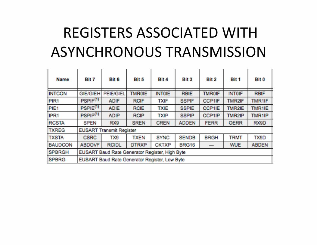
REGISTERS ASSOCIATED WITH ASYNCHRONOUS TRANSMISSION

REGISTERS ASSOCIATED WITH ASYNCHRONOUS RECEPTION

Example: • Assuming 9600 baud rate, Asynch, Clock frequency is 10 MHZ, 8 bit
character • What should we write into register SPBRG register? • We assume: SYNC = 0, BRGH = 0, BRG16 = 0
– Thus, baud rate = Fcso/[64(n+1)]àn=15
n=15

Example • This program allows to print characters on a remote PC terminal
• The clock seFng and interrupts are shown below.

C-‐ Version TransmiFng Characters
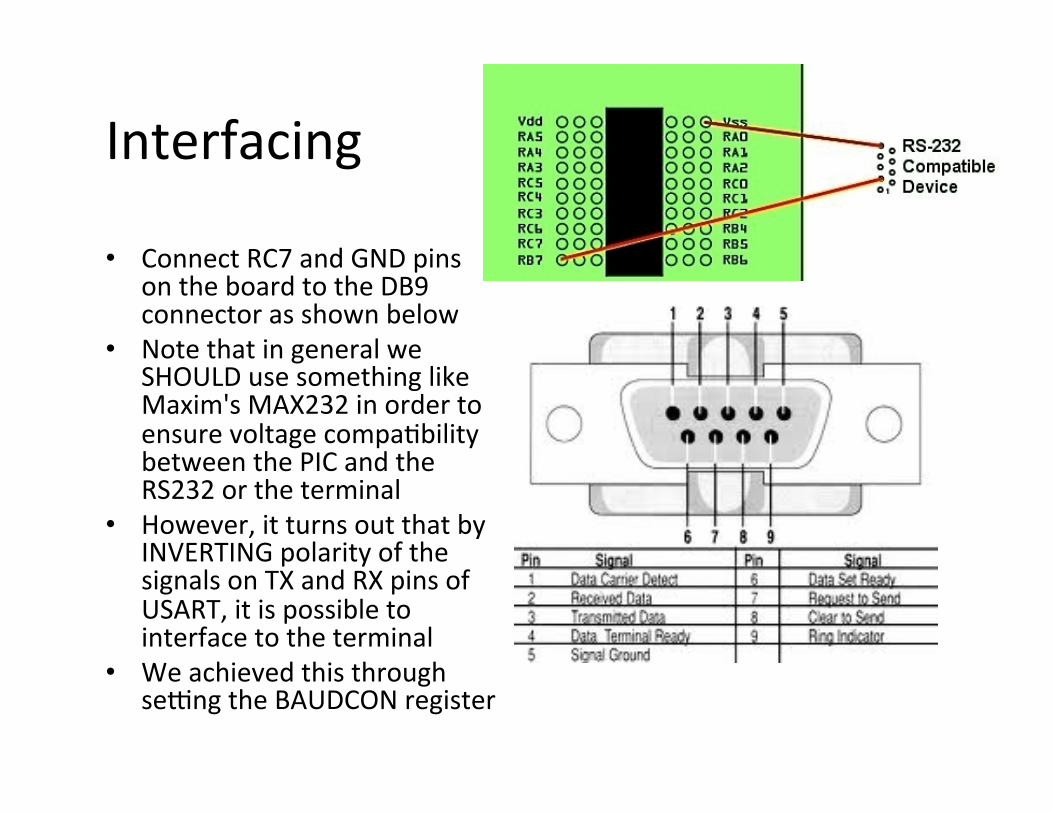
Interfacing
• Connect RC7 and GND pins on the board to the DB9 connector as shown below
• Note that in general we SHOULD use something like Maxim's MAX232 in order to ensure voltage compa)bility between the PIC and the RS232 or the terminal
• However, it turns out that by INVERTING polarity of the signals on TX and RX pins of USART, it is possible to interface to the terminal
• We achieved this through seFng the BAUDCON register
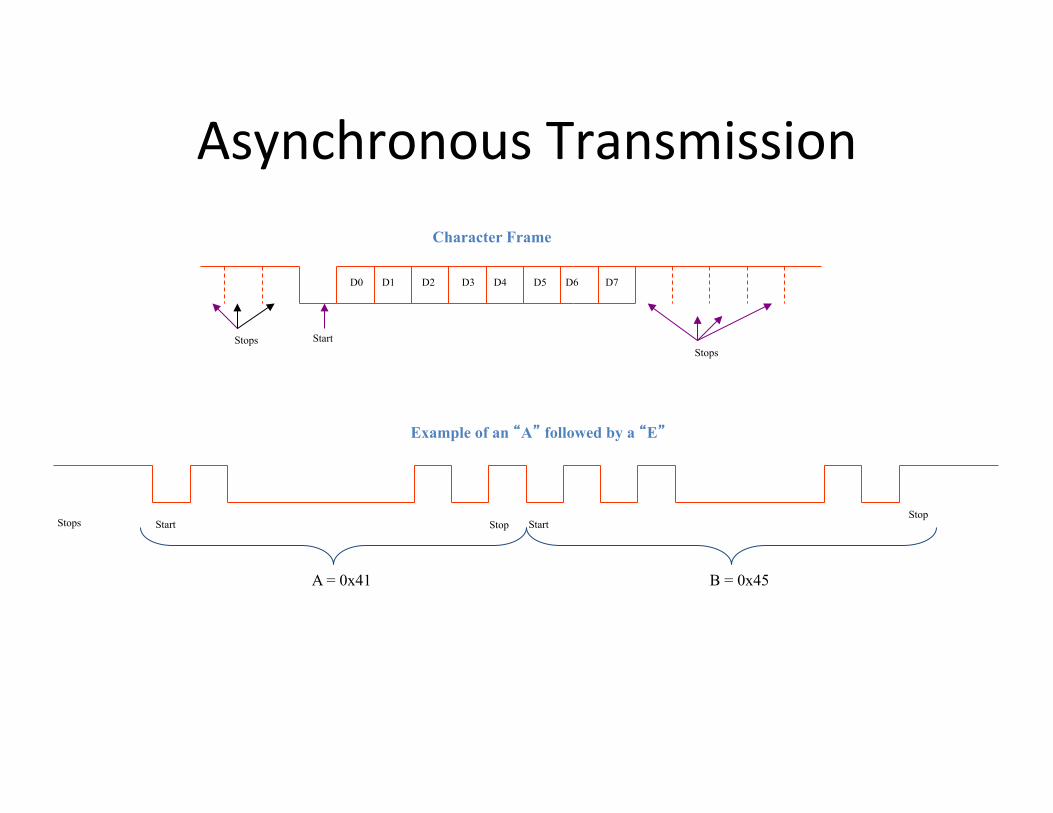
Asynchronous Transmission
Start
Start Start Stop
Stops Stops
Stops Stop
Character Frame
Example of an “A” followed by a “E”
A = 0x41 B = 0x45
D0 D1 D2 D3 D4 D5 D6 D7

Synchronous Transmission
Clock
Data
A = 0x41 B = 0x42

The USART interfaced to a standard DB9 connector for RS-‐232C data

Terminal • Download a PC terminal solware such as Hyper Terminal or RealTerm (hmp://sourceforge.net/projects/realterm/ )
• If you only have a USB port you may need a USB/Serial Cable and driver
• Set the Hyper Terminal to 9600, N,1,0 • Power up your board and run the program in DEBUG mode.
• You should see the characters displayed on the terminal
Make sure your PICKIT is connected to ICSP connector at all the )me. The interface to the PC is via pin 3 (GND) and pin 6 (TX) of
P2 connector on the board.

Output Displayed Using RealTerm (pay amen)on to the seFngs)

Baud Rate • Note that by probing TX pin (RC7) we
can ensure the baud rate is set properly
• The following is a sample calcula)on for determining the SPBRG value if the clock is 16 MHz
• Note that for 4 MHz clock the actual baud rate is 9615 bps, and error of 0.16 percent which is tolerable!
• It si also possible to use #pragma config FOSC = HS to generate 4MHz clock.

Baud Rate Measurement (about 9600 bps)
Transmimed datat

Tes)ng
• You can test your output in the Simula)on mode using the SIM Usart1 feature

LabVIEW (1)
• We have designed a LabVIEW VI to receive the transmimed data
• In this case HELLx is transmimed. X is an 8-‐bit random value.
• All the received values are plomed and saved in a file.
• See the VI in the next slide
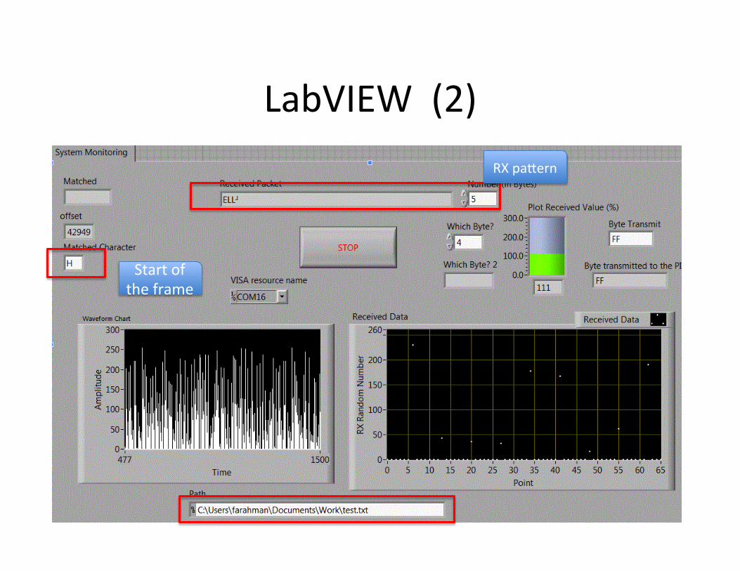
LabVIEW (2)
Start of the frame
RX pamern

LabVIEW (3) Prac)ce
• A few interes)ng changes to the LabVIEW program can be changed: – Create an alarm bumon such that if a value greater than 32 was detected, a RED LED is turned on and the buzzer is ac)vated.
– Count and display the number of inputs recorded in each session.
– In LabVIEW go to ToolsàBuild Applica)on (EXE) and create an executable file. Can you use this file on a PC that does not have LabVIEW solware?
– In LabVIEW go to ToolsàWeb Publishing and create a web-‐version of the program. You should be able to remotely monitor the received values. You can save the file as MONITOR. You will also need to download the RUNTIME program to interface with the VI remotely.
Receiving Bytes From PC
• We need to change the levels. • The PIC does not have sufficient forgivenes.

This is the signal from PC’s RS232