usa: control valves t: (978) 689-6066 • f: (978) 975 …media.wattswater.com/2915056.pdf · slow...
TRANSCRIPT
EN
GLIS
H I
NSTR
UC
TIO
NS
IS-A-AFBV-FP
Supervisory Switch Wiring(1) Switches supervise valve in “open” position
(2) Switch 1 is intended for connection to the supervisory circuit of a fire alarm control panel and has two 18 gauge wires per terminal. Switch 2 is intended for auxiliary service and has one 18 gauge wire per terminal and may be connected to a remote device such as a remote indicating light or audible bell.
Switch #1 S1 Normally Closed (NC): (2) Blue Common (C): (2) Yellow
Switch #2 S2 Normally Closed (NC): Blue with Orange Stripe Normally Open (NO): Brown with Orange Stripe Common (C): Yellow with Orange Stripe Ground (G): Green
The diagram shows a connection between the common terminal (yellow-S1) and the nor-mally closed terminal (blue-S1).
A similar connection is made between yellow-with-orange stripe-S2 and blue-with-orange stripe-S2. With this configuration, an indicator light or alarm would stay on until the valve is fully open. When the valve is fully open, the indicator light goes out and alarm will go. off. Any unused wires should be capped off.
Connection of the valves internal supervisory switches are to be made by qualified per-sonnel in accordance with NFPA 72, National Fire Alarm Code and NFPA 70, National Electrical Code.
GOBV Switch Repair Kit Installation Instructions1. Open repair kit and make sure all the replaceable parts are present
2. Disconnect product from power supply and unwire from external components
3. Pop plastic cap (1) off the orange indicator post
4. Unscrew anti-tamper screw TR10 (2) from the center of the orange indicator post
5. Remove orange indicator post (3) while noting its orientation
6. Unscrew all 4 anti-tamper TR10 screws (4) on corners of red switch box
Note: On diagram one of the four screws is obstructed from view by diagram of indicator post
7. Remove red switch box cover (5). While removing cover place finger on brass yoke which protrudes from whole in switch box cover, to make sure it’s not removed with cover. If it does get removed, make sure to replace it at the previously installed orien-tation.
8. Remove rubber gasket (6) from main body
9. Locate all the necessary parts from the repair kit
10. From the repair kit, use all the necessary parts needed to replace them at the for-mer locations, to make the valve function properly. For assembly, it is the reverse order of dissembling. The assembly order: (6) rubber guard, (5) red switch box, (4) 4 anti-tamper TR10 screws on the corners of the red switch box, (3) orange indicator post, (2) anti-tamper screw TR10 in the center of the indicator post, (1) plastic cap on top of the indicator post
11. Adhere nameplate (7) to new switchbox cover. Choose 1 nameplate out of the two in the repair kit. If your valve is threaded, choose the nameplate that says “FP”. If your valve is grooved, choose the nameplate that says “FP-GV”. Use the stick screws to attach the nameplate as shown (8). After each screw, break the stick off from the utilized screw.
12. Rewire the part as instructed
13. Discard all extra components
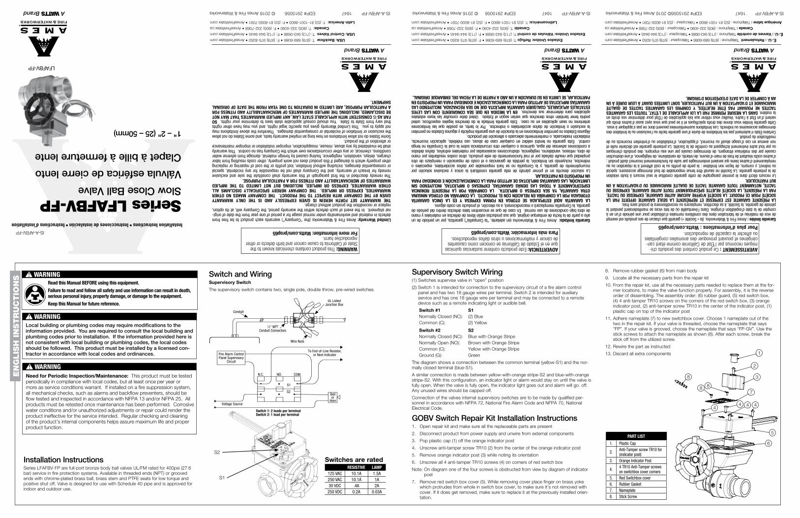
Series LFAFBV-FPSlow Close Ball Valve
Válvula esférica de cierre lento
Clapet à bille à fermeture lente
1" – 2" (25 – 50mm)
LFAFBV-FP
IS-A-AFBV-FP 1647 EDP# 2915056 © 2016 Ames Fire & Waterworks IS-A-AFBV-FP 1647 EDP# 2915056 © 2016 Ames Fire & Waterworks IS-A-AFBV-FP 1647 EDP# 2915056 © 2016 Ames Fire & Waterworks
WARNING: This product contains chemicals known to the State of California to cause cancer and birth defects or other reproductive harm.For more information: Watts.com/prop65
ADVERTENCIA: Este producto contiene sustancias químicas que en el Estado de California se conocen como causantes de cáncer y malformaciones u otros daños reproductivos.Para más información: Watts.com/prop65
AVERTISSEMENT : Ce produit contient des produits chi-miques reconnus par l’État de Californie comme étant can-cérigènes et pouvant provoquer des anomalies congénitales ou affecter la capacité de reproduction.Pour plus d'informations : Watts.com/prop65
USA: Backflow T: (978) 689-6066 • F: (978) 975-8350 • AmesFireWater.com
USA: Control Valves T: (713) 943-0688 • F: (713) 944-9445 • AmesFireWater.com
Canada: T: (905) 332-4090 • F: (905) 332-7068 • AmesFireWater.ca
Latin America: T: (52) 81-1001-8600 • F: (52) 81-8000-7091 • AmesFireWater.com
Estados Unidos: Reflujo T: (978) 689-6066 • F: (978) 975-8350 • AmesFireWater.com
Estados Unidos: Válvulas de control T: (713) 943-0688 • F: (713) 944-9445 • AmesFireWater.com
Canadá: T: (905) 332-4090 • F: (905) 332-7068 • AmesFireWater.ca
Latinoamérica: T: (52) 81-1001-8600 • F: (52) 81-8000-7091 • AmesFireWater.com
É.-U. : Refoulement Téléphone : (978) 689-6066 • Télécopieur : (978) 975-8350 • AmesFireWater.com
É.-U. : Vannes de contrôle Téléphone : (713) 943-0688 • Télécopieur : (713) 944-9445 • AmesFireWater.com
Canada : Téléphone : (905) 332-4090 • Télécopieur : (905) 332-7068 • AmesFireWater.ca
Amérique latine : Téléphone : (52) 81-1001-8600 • Télécopieur : (52) 81-8000-7091 • AmesFireWater.com
Limited Warranty: Ames Fire & Waterworks (the “Company”) warrants each product to be free from defects in material and workmanship under normal usage for a period of one year from the date of origi-nal shipment. In the event of such defects within the warranty period, the Company will, at its option, replace or recondition the product without charge. THE WARRANTY SET FORTH HEREIN IS GIVEN EXPRESSLY AND IS THE ONLY WARRANTY GIVEN BY THE COMPANY WITH RESPECT TO THE PRODUCT. THE COMPANY MAKES NO OTHER WARRANTIES, EXPRESS OR IMPLIED. THE COMPANY HEREBY SPECIFICALLY DISCLAIMS ALL OTHER WARRANTIES, EXPRESS OR IMPLIED, INCLUDING BUT NOT LIMITED TO THE IMPLIED WARRANTIES OF MERCHANTABILITY AND FITNESS FOR A PARTICULAR PURPOSE.The remedy described in the first paragraph of this warranty shall constitute the sole and exclusive remedy for breach of warranty, and the Company shall not be responsible for any incidental, special or consequential damages, including without limitation, lost profits or the cost of repairing or replacing other property which is damaged if this product does not work properly, other costs resulting from labor charges, delays, vandalism, negligence, fouling caused by foreign material, damage from adverse water conditions, chemical, or any other circumstances over which the Company has no control. This warranty shall be invalidated by any abuse, misuse, misapplication, improper installation or improper maintenance or alteration of the product. Some States do not allow limitations on how long an implied warranty lasts, and some States do not allow the exclusion or limitation of incidental or consequential damages. Therefore the above limitations may not apply to you. This Limited Warranty gives you specific legal rights, and you may have other rights that vary from State to State. You should consult applicable state laws to determine your rights. SO FAR AS IS CONSISTENT WITH APPLICABLE STATE LAW, ANY IMPLIED WARRANTIES THAT MAY NOT BE DISCLAIMED, INCLUDING THE IMPLIED WARRANTIES OF MERCHANTABILITY AND FITNESS FOR A PARTICULAR PURPOSE, ARE LIMITED IN DURATION TO ONE YEAR FROM THE DATE OF ORIGINAL SHIPMENT.
Garantía limitada: Ames Fire & Waterworks (en adelante, “la Compañía”) garantiza, por un período de un año a partir de la fecha de embarque original, que sus productos están libres de defectos en materiales y mano de obra bajo condiciones de uso normal. En caso de que se encuentren tales defectos dentro del período de garantía, la Compañía reemplazará o reacondicionará, a su elección, el producto sin costo alguno. LA GARANTÍA AQUÍ ESTIPULADA SE OTORGA EN FORMA EXPRESA Y ES LA ÚNICA GARANTÍA OTORGADA POR LA COMPAÑÍA EN RELACIÓN CON EL PRODUCTO. LA COMPAÑÍA NO OTORGA NINGUNA OTRA GARANTÍA, YA SEA EXPRESA O IMPLÍCITA. LA COMPAÑÍA POR LA PRESENTE RENUNCIA ESPECÍFICAMENTE A TODAS LAS DEMÁS GARANTÍAS, EXPRESAS O IMPLÍCITAS, INCLUYENDO SIN LIMITACIÓN, LAS GARANTÍAS IMPLÍCITAS DE APTITUD PARA LA COMERCIALIZACIÓN E IDONEIDAD PARA UN PROPÓSITO EN PARTICULAR. La solución descrita en el primer párrafo de esta garantía constituirá la única y exclusiva solución por incumplimiento de garantía, y la Compañía no se hará responsable por daños accidentales, especiales o indirectos, incluyendo sin limitación, la pérdida de ganancias o el costo de reparación o reemplazo de otra propiedad que resulte dañada por el mal funcionamiento de este producto, otros costos resultantes por mano de obra, retrasos, vandalismo, negligencia, obstrucciones ocasionadas por materiales extraños, daños debidos a condiciones adversas del agua, químicos o cualquier otra circunstancia sobre la cual la Compañía no tenga control. Esta garantía no tendrá validez en cualquier caso de abuso, uso indebido, aplicación incorrecta, instalación inadecuada, o mantenimiento adecuado o alteración del producto. Algunos Estados no permiten limitaciones en la duración de una garantía implícita y algunos Estados no permiten la exclusión o limitación de daños accidentales o indirectos. Por lo tanto, es posible que las limitaciones anteriores no sean aplicables en su caso. Esta garantía limitada le da derechos legales específicos; usted podría tener también otros derechos que varían según el Estado. Usted debe consultar las leyes estatales aplicables para determinar sus derechos. EN LA MEDIDA EN QUE SEA CONGRUENTE CON LAS LEYES ESTATALES APLICABLES, CUALQUIER GARANTÍA IMPLÍCITA QUE NO SEA RECHAZADA, INCLUYENDO LAS GARANTÍAS IMPLÍCITAS DE APTITUD PARA LA COMERCIALIZACIÓN E IDONEIDAD PARA UN PROPÓSITO EN PARTICULAR, SE LIMITA EN SU DURACIÓN A UN AÑO A PARTIR DE LA FECHA DEL EMBARQUE ORIGINAL.
Garantie limitée : Ames Fire & Waterworks. (la « Société ») garantit que chacun de ses produits est exempt de vice de matériau et de fabrication dans des conditions normales d’utilisation pour une période d’un an à compter de la date d’expédition d’origine. Dans l’éventualité où de tels vices se manifesteraient pendant la période de garantie, la Société, à sa discrétion, remplacera ou reconditionnera le produit sans frais. LA PRÉSENTE GARANTIE EST EXPRESSE ET REPRÉSENTE LA SEULE GARANTIE OFFERTE PAR LA SOCIÉTÉ POUR CE PRODUIT. LA SOCIÉTÉ N’OFFRE AUCUNE AUTRE GARANTIE, EXPRESSE OU TACITE. PAR LA PRÉSENTE, LA SOCIÉTÉ REJETTE SPÉCIFIQUEMENT TOUTE AUTRE GARANTIE, EXPRESSE OU TACITE, NOTAMMENT TOUTE GARANTIE TACITE DE QUALITÉ MARCHANDE OU D’ADAPTATION À UN BUT PARTICULIER. Le recours décrit dans le premier paragraphe de cette garantie constitue le seul recours à toute violation de la présente garantie. La Société ne saurait être tenue responsable de tout dommage accessoire, spécial ou indirect, y compris, de façon non limitative : la perte de profits ou le coût afférent à la réparation ou au remplacement d’autres biens qui seraient endommagés par suite du fonctionnement incorrect dudit produit ; d’autres coûts résultant de frais de main-d’œuvre, de retards, de vandalisme, de négligence, d’une obstruction causée par des matériaux étrangers, de dommages causés par une eau impropre, des produits chimiques ou par tout autre événement échappant au contrôle de la Société. La présente garantie est déclarée nulle et non avenue en cas d’usage abusif ou incorrect, d’application, d’installation ou d’entretien incorrects ou de modification du produit. Certains États n’autorisent pas les limitations de durée d’une garantie tacite ou l’exclusion ou la limitation des dommages accessoires ou indirects. Les limitations susmentionnées peuvent donc ne pas s’appliquer à vous. Cette garantie limitée vous donne des droits spécifiques et il se peut que vous ayez aussi d’autres droits qui varient d’un État à l’autre. Veuillez vous référer aux lois applicables de l’État pour déterminer vos droits en la matière. DANS LA MESURE PERMISE PAR LA LOI APPLICABLE DE L’ÉTAT, TOUTES LES GARANTIES TACITES NE POUVANT PAS ÊTRE REJETÉES, Y COMPRIS LES GARANTIES TACITES DE QUALITÉ MARCHANDE ET D’ADAPTATION À UN BUT PARTICULIER, SONT LIMITÉES QUANT À LEUR DURÉE À UN AN À COMPTER DE LA DATE D’EXPÉDITION D’ORIGINE.
Installation Instructions • Instrucciones de instalación • Instructions d’installation
Installation InstructionsSeries LFAFBV-FP are full-port bronze body ball valves UL/FM rated for 400psi (27.6 bar) service in fire protection systems. Available in threaded ends (NPT) or grooved ends with chrome-plated brass ball, brass stem and PTFE seats for low torque and positive shut off. Valve is designed for use with Schedule 40 pipe and is approved for indoor and outdoor use.
Bell or
Horn
UL Listed Junction Box
Conduit
N.C. NO.
S1
S2
COM.
1⁄2" NPT Conduit Connectors
Wire Nuts
Fire Alarm Control Panel Supervisory
Circuit
To End-of-Line Resistor, or Next Indicator
Switch 1: 2 leads per terminalSwitch 2: 1 lead per terminal
Voltage Source
S1
S2
Switch and WiringSupervisory Switch
The supervisory switch contains two, single pole, double throw, pre-wired switches.
RESISTIVE LAMP125 VAC 10.1A 1.5A250 VAC 10.1A 1A30 VDC .4A 2A250 VDC 0.2A 0.03A
Switches are rated
PART LIST
1. Plastic Cap
2. Anti-Tamper screw TR10 for (indicator post)
3. Orange Indicator Post
4. 4 TR10 Anti-Tamper screws on switchbox cover corners
5. Red Switchbox cover6. Rubber Gasket7. Nameplate8. Stick Screw
WARNING!Read this Manual BEFORE using this equipment.
Failure to read and follow all safety and use information can result in death, serious personal injury, property damage, or damage to the equipment.
Keep this Manual for future reference.
Local building or plumbing codes may require modifications to the information provided. You are required to consult the local building and plumbing codes prior to installation. If the information provided here is not consistent with local building or plumbing codes, the local codes should be followed. This product must be installed by a licensed con-tractor in accordance with local codes and ordinances.
WARNING!
Need for Periodic Inspection/Maintenance: This product must be tested periodically in compliance with local codes, but at least once per year or more as service conditions warrant. If installed on a fire suppression system, all mechanical checks, such as alarms and backflow preventers, should be flow tested and inspected in accordance with NFPA 13 and/or NFPA 25. All products must be retested once maintenance has been performed. Corrosive water conditions and/or unauthorized adjustments or repair could render the product ineffective for the service intended. Regular checking and cleaning of the product’s internal components helps assure maximum life and proper product function.
WARNING!
1
2
3
88
44 4 4
5
6
8
7
1
2
3
7
44 4 4
5
6
88
8

INSTR
UC
CIO
NE
S E
N E
SP
AÑ
OL
INST
RU
CT
ION
S E
N F
RA
NÇ
AIS
ADVERTENCIA!Lea este manual ANTES de utilizar este equipo.
El no leer y seguir todas las medidas de seguridad y usar la información puede causar la muerte, lesiones personales graves, daños materiales o daños en el equipo.
Guarde este manual para referencia futura.
Los códigos locales de construcción o fontanería pueden requerir modificaciones en la información proporcionada Es obligatorio consultar los códigos locales de construcción y fontanería antes de comenzar la instalación. Si la información de este manual no se corresponde con los códigos locales de construcción y fontanería, deberán seguirse estos últimos. Este producto debe ser instalado por un contratista con licencia, de acuerdo con los códigos y ordenanzas locales.
AVERTISSEMENT!Lisez attentivement ce manuel avant d'utiliser cet équipement.
Négliger de lire et de suivre toutes les consignes de sécurité et d'utilisation de l'information peut entraîner la mort, des blessures graves ou des dégâts matériels, ou endommager l'équipement.
Veuillez conserver ce manuel pour toute référence ultérieure.
Les codes locaux du bâtiment ou de la plomberie peuvent nécessiter des modifications aux renseignements donnés. Vous êtes tenus de consulter des codes locaux du bâtiment ou de la plomberie avant de commencer l’installation. Si les renseignements donnés ci-dessous ne sont pas cohérents avec les codes locaux du bâtiment ou de la plomberie, les codes locaux doivent être respectés. Ce produit doit être installé par un entrepreneur licencié conformément aux codes et règlements locaux.
AVERTISSEMENT!
Requerimiento de inspección periódica/mantenimiento: Este producto debe ser evaluado periódicamente de acuerdo con los códigos locales, pero al menos una vez o más al año según las condiciones del servicio. Si se instala en un sistema antiincendios, se deberán inspeccionar todas las válvulas mecánicas, como alarmas o sistemas de retención, y se les deberá realizar una evaluación de flujo de acuerdo con los estándares NFPA 13 y/o NFPA 25. Todos los productos deben volver a ser evaluados una vez se haya realizado el mantenimiento. Condiciones de agua corrosiva y/o ajustes o reparaciones no autorizados pueden provocar que el producto deje de funcionar para el servicio previsto. Una inspección y limpieza regulares de los componentes internos del producto garantizan la vida máxima y el adecuado funcionamiento del producto.
ADVERTENCIA!
Nécessité d’inspection périodique/maintenance: Ce produit doit être testé périodiquement en conformité avec les codes locaux, mais au moins une fois par an ou plus, comme les conditions de service le justifient. S’il est installé sur un système d’extinction d’incendie, tous les contrôles mécaniques, tels que les alarmes et obturateurs, doivent être testés et inspectés conformément à la norme NFPA 13 et/ou NFPA 25. Tous les produits doivent être testés une fois que les opérations d’entretien ont été effectuées. Des conditions d’admission corrosives et/ou des réglages ou des réparations non autorisés peuvent rendre le produit inefficace pour le service prévu. Un contrôle régulier et le nettoyage des composants internes du produit permettent d’assurer la durée de vie et le bon fonctionnement du produit.
AVERTISSEMENT!
ADVERTENCIA!
Câblage des interrupteurs de surveillance(1) Les interrupteurs surveillent le clapet en position « ouverte »
(2) L'interrupteur 1 est conçu pour être raccordé au circuit de surveillance du panneau de contrôle d'une alarme incendie et est doté de deux fils de diamètre 18 par borne. L'interrupteur 2 est conçu pour le service auxiliaire et est doté d'un fil de diamètre 18 par borne. Il peut être raccordé à un dispositif à distance, notamment un témoin lumineux distant ou une alarme sonore.
Interrupteur 1 S1 Normalement fermé (NF) : (2) Bleu Commun (C) : (2) Jaune
Interrupteur 2 S2 Normalement fermé (NF) : Bleu avec une ligne orange Normalement ouvert (NO) : Brun avec une ligne orange Commun (C) : Jaune avec une ligne orange Mise à la terre (T) : Vert
Le diagramme montre une connexion entre la borne commune (jaune-S1) et la borne normalement fermée (bleu-S1).
Une connexion similaire est effectuée entre S2 jaune avec une ligne orange et S2 bleu avec une ligne orange. Avec cette configuration, un témoin lumineux ou une alarme sonore reste allumé(e) jusqu'à ce que le clapet soit complètement ouvert. Lorsque le clapet est complètement ouvert, le témoin lumineux s'éteint ou l'alarme s'arrête. Tout fil non utilisé doit être recouvert.
Le raccord des interrupteurs de surveillance internes des clapets doit être réalisé par un technicien qualifié conformément au Code national de prévention des incendies (NFPA 72) et au Code national de l'électricité (NFPA 70).
Instructions d'installation de la trousse de réparation des interrupteurs GOBV1. Ouvrez la trousse de réparation et assurez-vous que toutes les pièces remplaçables
sont présentes.2. Débranchez le produit de l'alimentation et débranchez les fils des composants externes.3. Retirez le capuchon en plastique (1) de l'indicateur orange.4. Dévissez la vis inviolable TR10 (2) au centre de l'indicateur orange.5. Retirez l'indicateur orange (3) en prenant note de son orientation.6. Dévissez les quatre vis inviolables TR10 (4) aux angles du couvercle du boîtier
électrique rouge.Remarque : sur le diagramme, l'une des quatre vis est masquée par le diagramme
de l'indicateur.
7. Retirez le couvercle du boîtier électrique rouge (5). En retirant le couvercle, placez votre doigt sur le bras en laiton qui ressort du trou dans le couvercle du boîtier électrique pour vous assurer qu'il reste en place. S'il devait se détacher par inadvertance, veillez à le réinstaller dans le bon sens.
8. Retirez le joint en caoutchouc (6) du corps principal. 9. Localisez les pièces nécessaires dans la trousse de réparation.10. Utilisez toutes les pièces de remplacement de la trousse de réparation
nécessaires pour faire fonctionner à nouveau le clapet. Pour les assembler, procédez dans l'ordre inverse du démontage. Ordre d'assemblage : (6) joint en caoutchouc, (5) boîtier électrique rouge, (4) 4 vis inviolables TR10 aux coins du boîtier électrique rouge, (3) indicateur orange, (2) vis inviolables TR10 au centre de l'indicateur orange, (1) couvercle en plastique sur l'indicateur
11. Apposez la plaque signalétique (7) sur le nouveau couvercle du boîtier électrique. Choisissez l'une des deux plaques signalétiques incluses dans la trousse de réparation. Si votre clapet est fileté, choisissez la plaque signalétique marquéee « FP ». Si votre clapet est rainuré, choisissez la plaque signalétique marquée « FP-GV ». Utilisez les longues vis pour attacher la plaque signalétique comme illustré (8). Cassez la longueur inutilisée de chaque vis.
12. Réinstallez les fils de la pièce en suivant les consignes.
13. Mettez les composants additionnels au rebut.
Instructions d’installationLa série LFAFBV-FP de clapets à bille en laiton est homologuée UL/FM pour une pression de service de 400 psi (27,6 bar) dans les systèmes de protection contre les incendies. Disponibles avec des extrémités filetées (NPT) ou rainurées avec une bille en laiton chromé, une tige en laiton et des sièges PTFE pour couple faible et arrêt positif. Le clapet est conçu pour être utilisé avec les tuyaux de série 40 et est homologué pour un usage en intérieur ou à l'extérieur.
Sonnette ou avertisseur
Boîte de jonction homologuée UL
Conduit
NF NO
S1
S2
COM.
Connecteurs de conduit 1⁄2 po NPT
Capuchons de connexion
Circuit de surveillance du panneau de contrôle
d'alarme incendie
Vers la résistance d'extrémité de ligne ou
l'indicateur suivant
Interrupteur 1 : 2 fils par borneInterrupteur 2 : 1 fil par borne
Source de tension
S1
S2
Interrupteur et câblageInterrupteur de surveillance
L'interrupteur de surveillance contient deux interrupteurs unipolaires bidirectionnels précâblés.
RÉSISTANT LAMPE
125 V c.a. 10,1 A 1,5 A
250 V c.a. 10,1 A 1 A
30 V c.c. 0,4 A 2 A
250 V c.c. 0,2 A 0,03 A
Valeurs nominales des interrupteurs
LISTE DES PIÈCES
1. Capuchon en plastique
2. Vis inviolable TR10 (indicateur)
3. Indicateur orange
4.4 vis inviolables TR10 aux coins du couvercle du boîtier électrique
5. Couvercle du boîtier électrique rouge
6. Joint en caoutchouc7. Plaque signalétique8. Longue vis
1
2
3
88
44 4 4
5
6
8
7
1
2
3
7
44 4 4
5
6
88
8
Cableado del interruptor de supervisión(1) Cambie la válvula de supervisión a la posición “abierta”
(2) El interruptor 1 está diseñado para conectarse al circuito supervisor de un tablero de control de alarma de incendio y tiene dos cables calibre 18 por terminal. El interruptor 2 está diseñado para servicio auxiliar, tiene un cable calibre 18 por terminal y puede conectarse a un dispositivo remoto, como una luz indicadora o una campana audible.
Interruptor 1 S1 Normalmente cerrado (NC): (2) Azul Común (C): (2) Amarillo
Interruptor 2 S2 Normalmente cerrado (NC): Azul con franja anaranjada Normalmente abierto (NA): Café con franja anaranjada Común (C): Amarillo con franja anaranjada Tierra (T): Verde
El diagrama muestra una conexión entre el terminal común (amarillo S1) y el terminal normalmente cerrado (azul S1).Se hace una conexión similar entre el cable amarillo con franja anaranjada S2 y el cable azul con franja anaranjada S2. Con esta configuración, una luz indicadora o alarma permanecerá encendida hasta que la válvula esté totalmente abierta. Una vez que la válvula esté totalmente abierta, la luz indicadora y la alarma se apagarán. Deberán colocarse tapones en todos los cables no usados.La conexión de los interruptores supervisores internos de las válvulas debe ser realizada por personal calificado de conformidad con NFPA 72, Código Nacional de Alarmas de Incendio, y NFPA 70, Código Eléctrico Nacional.
Instrucciones de instalación para el kit de reparación del interruptor GOBV1. Abra el kit de reparación y compruebe que todas las piezas para reemplazo estén presentes.2. Desconecte el producto de la fuente de alimentación y desconecte los cables de los
componentes externos.3. Quite el tapón de plástico (1) del poste indicador anaranjado.4. Destornille el tornillo contra vandalismo TR10 (2) del centro del poste indicador
anaranjado.5. Quite el poste indicador anaranjado (3) tomando nota de su orientación.6. Destornille los cuatro tornillos contra vandalismo TR10 (4) en las esquinas de la caja de
interruptores roja.Nota: En el diagrama, la visibilidad de uno de los cuatro tornillos está obstruida por el
diagrama del poste indicador.
Instrucciones de instalaciónLa serie LFAFBV-FP consta de válvulas esféricas de latón de puerto completo homologadas por UL/FM para servicio de 400 psi (27.6 bar) en sistemas de protección contra incendios. Disponibles con extremos roscados (NPT) o ranurados con esfera de latón cromado, vástago de latón y asientos de PTFE para crear un bajo par de torsión y un cierre positivo. La válvula está diseñada para usarse con tubería de cédula 40 y está aprobada para uso en interiores y exteriores.
Campana o bocina
Caja de conexiones homologada por UL
Conducto
N.C. N.A.
S1
S2
COM.
Conectores para conducto 1⁄2" NPT
Tuercas para cables
Circuito supervisor de tablero de control de alarmas de incendio
Al resistor de fin de línea o al siguiente indicador
Interruptor 1: 2 cables por terminalInterruptor 2: 1 cable por terminal
Fuente de voltaje
S1
S2
Interruptor y cableadoInterruptor de supervisión
El interruptor de supervisión contiene dos interruptores precableados de un polo, doble tiro.
RESISTIVO LÁMPARA125 VCA 10.1 A 1.5 A
250 VCA 10.1 A 1 A
30 VCC 0.4 A 2 A
250 VCC 0.2 A 0.03 A
Homologación de los interruptores
LISTA DE PIEZAS
1. Tapón de plástico
2.Tornillo contra vandalismo TR10 para (poste indicador)
3. Poste indicador anaranjado
4.Cuatro tornillos contra vandalismo TR10 en las esquinas de la tapa de la caja de interruptores
5. Tapa de caja de interruptores roja
6. Junta de goma
7. Placa de datos
8. Tornillo con poste
1
2
3
88
44 4 4
5
6
8
7
1
2
3
7
44 4 4
5
6
88
8
7. Quite la tapa de la caja de interruptores roja (5). Al quitar la cubierta, ponga el dedo en el yugo de latón que sobresale por el agujero en la tapa de la caja de interruptores, para asegurarse de no retirarlo con la tapa. Si llega a retirarlo, asegúrese de volver a colocarlo con la misma orientación con la que estaba instalada.
8. Separe la junta de goma (6) del cuerpo principal. 9. Localice todas las piezas necesarias del kit de reparación.10. Use todas las piezas necesarias del kit de reparación como reemplazo en su lugar
anterior, para que la válvula funcione correctamente. Para el armado, siga las instrucciones de desarmado en orden inverso. Orden de armado: (6) protector de goma, (5) caja de interruptores roja, (4) cuatro tornillos contra vandalismo TR10 en las esquinas de la caja de interruptores roja, (3) poste indicador anaranjado, (2) tornillo contra vandalismo TR10 en el centro del poste indicador, (1) tapón de plástico en la parte superior del poste indicador.
11. Adhiera la placa de datos (7) a la nueva tapa de la caja de interruptores. Seleccione una de las dos placas de datos en el kit de reparación. Si la válvula está roscada, seleccione la placa de datos que dice “FP”. Si la válvula está ranurada,seleccione la placa de datos que dice “FP-GV”. Use los tornillos con poste para sujetar la placa de datos en la forma ilustrada (8). Después de cada tornillo, rompa el poste del tornillo utilizado.
12. Vuelva a cablear la pieza en la forma indicada.
13. Deseche los componentes sobrantes.