u.s. robotics 56 kbps internal and external...
TRANSCRIPT

This manual covers installation and operating instructions for the following 3Com modems:
U.S. Robotics 56 Kbps∗ internal and external modems
U.S. Robotics is a registered trademark and Connections, RapidComm, and x2 are trademarks of3Com Corporation and its subsidiaries. Windows is a registered trademark of Microsoft Corp.CompuServe is a registered trademark of CompuServe Inc. America Online is a registered trademarkof America Online Inc. Any other trademarks, trade names, or service marks used in this manual arethe property of their respective owners.
© 1998 3Com Corporation7770 North Frontage RoadSkokie, IL 60077-2690All Rights Reserved
∗∗ IMPORTANT! In accordance with the ITU-T standard for 56K transmissions, this modem is capableof 56 Kbps downloads. However, due to FCC rules which restrict power output of the serviceproviders’ modems, current download speeds are limited to 53 Kbps. Actual speeds may varydepending on line conditions and other factors. Uploads from users to server equipment travel atspeeds up to 31.2 Kbps. An analog phone line compatible with the ITU-T 56K standard or x2technology, and an Internet provider or corporate host site compatible with the ITU-T 56K standardor x2 technology are necessary for these high-speed downloads.
Table of ContentsWelcome to 56K Information Access ....................................................................................1Product Features..................................................................................................................... 2Internal Modem Installation with Windows 3.x................................................................. 3
A Word about COM Ports and IRQs ..............................................................................3How to Use ComTest to Determine Your Modem’s Settings............................................5Testing an Installed Modem..............................................................................................7What to Do with ComTest’s Recommendation.................................................................8How to Change the Modem’s Settings ...........................................................................10How to Insert the Modem into the Computer..................................................................13
Internal Modem Installation with Windows 95 ............................................................... 21Plug and Play Installation................................................................................................21How to Prepare for Plug and Play Installation.................................................................22
Check Your System’s Resources .......................................................................22Find Out Which Version of Windows 95 You Have ...........................................23Check the Jumpers ............................................................................................24
How to Insert the Modem into the Computer..................................................................26How to Move Through the Screens You See When Windows Restarts...........................31
If You Have Windows 95 Version 950 or 950a .................................................31If You Have Windows 95 Version 950b ............................................................36
External Modem Installation with Windows 3.x..............................................................41How to Determine Which Serial Cable to Buy................................................................41How to Connect the Modem to the Computer................................................................42

External Modem Installation with Windows 95...............................................................45How to Determine Which Serial Cable to Buy................................................................45How to Find Out Which Version of Windows 95 You Have..........................................47How to Connect the Modem to the Computer................................................................48How to Move Through the Screens You See When Windows Restarts...........................50
If You Have Windows 95 Version 950 or 950a .................................................50If You Have Windows 95 Version 950b ............................................................55
Software Installation ......................................................................................................... 60Starting the Wizard ........................................................................................................61Installing the RapidComm™ Fax/Data Software.............................................................62
Installing Other Fax/Data Software ................................................................................. 64Type of Modem.............................................................................................................64Initialization String..........................................................................................................64Flow Control .................................................................................................................65UART (External Modems Only).....................................................................................65
Using Modem Station......................................................................................................... 66What Does Modem Station Do?....................................................................................66Why Modem Station?....................................................................................................66Installing Modem Station................................................................................................66Starting Modem Station .................................................................................................69Using Detect New Modems...........................................................................................71

Using Terminal...............................................................................................................72Using Modem Configurator............................................................................................74Using Modem to Computer............................................................................................77Using the Extended Information Screens.........................................................................81
U.S. Robotics Modem Update Wizard...............................................................................88Installing the Wizard.......................................................................................................89Updating Your Modem .................................................................................................89
Troubleshooting and Online Help Resources.................................................................. 90Problems and Solutions..................................................................................................90Online Help Resources.................................................................................................105Are You Still Having Problems?...................................................................................108If You Need to Return the Modem to Us for Repair .....................................................109
Glossary ...............................................................................................................................110Regulatory Information .....................................................................................................124
Manufacturer’s Declaration of Conformity....................................................................124Caution to the User......................................................................................................125IC (Canada) ................................................................................................................125UL Listing/CUL Listing................................................................................................125Connecting to the Telephone Company ........................................................................126Fax Branding...............................................................................................................126Radio and Television Interference.................................................................................127For Canadian Modem Users........................................................................................128Limited Warranty.........................................................................................................131

WELCOME TO 56K* INFORMATION ACCESS
1
The International Telecommunications Union(ITU) decides the technical protocolscommunications devices must use tointeroperate with each other. Modems thatcomply with ITU standards can “talk to” otherstandards-compliant modems and faxmachines worldwide.
The ITU has decided on a worldwide 56Kstandard technology. So, now with aU.S. Robotics modem you can get all theInternet you want from any service providerwho offers the ITU standard 56K technologyor x2™ technology.
This modem will give you the mostcompatibility with high speed downloads fromservice providers that offer the ITU 56Kstandard technology or x2 technology to theircustomers. 3Com is working with providerseverywhere to quickly upgrade their service tothe ITU 56K standard.
* Capable of receiving up to 56 Kbps and sendingup to 31.2 Kbps. Due to FCC regulations, receivingspeeds are limited to 53 Kbps. Actual speeds mayvary. Requires compatible phone line and serverequipment. Complies with both the proposed ITU56K standard and x2 protocols. ITU 56K standardofficially determined in February, 1998; expected tobe ratified in September, 1998. Seewww.3com.com/56k

PRODUCT FEATURES
2
Modulation Schemes56K ITU-T standardx2™ technologyITU-T V.34+ITU-T V.34ITU-T V.32bisITU-T V.32ITU-T V.22bisITU-T V.22ITU-T V.23Bell 212AITU-T V.21Bell 103
Error Control and DataCompression Schemes
ITU-T V.42ITU-T V.42bisMNP 2-5
Fax Modulation SchemesITU-T V.17ITU-T V.29ITU-T V.27terITU-T V.21
Fax StandardsEIA 578 Class 1 FAXEIA 592 Class 2.0 FAX
Front Channel Link Rates28000, 29333, 30666, 32000,33333, 34666, 36000, 37333,38666, 40000, 41333, 42666,44000, 45333, 46666, 48000,49333, 50666, 52000, 53333,54666, 56000, 57333
Back Channel Link Rates4800, 7200, 9600, 12000, 14400,16800, 19200, 21600, 24000,26400, 28800, 3120033600
V.34+ Link Rates4800, 7200, 9600, 12000, 14400,16800, 19200, 21600, 24000,26400, 28800, 31200, 33600
V.32bis Link Rates4800, 7200, 9600, 12000, 14400
Additional Link Rates300, 1200/75 (V.23), 1200, 2400
Fax Link Rates2400, 4800, 7200, 9600,12000, 14400
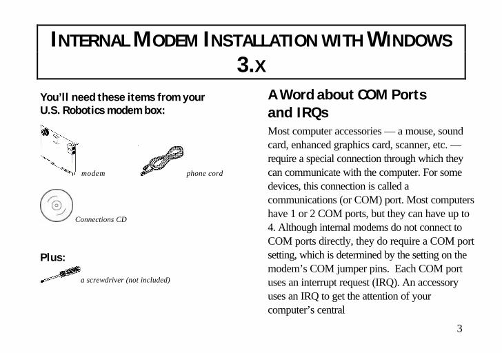
INTERNAL MODEM INSTALLATION WITH WINDOWS
3.X
3
You’ll need these items from yourU.S. Robotics modem box:
modem phone cord
Connections CD
Plus:
a screwdriver (not included)
A Word about COM Portsand IRQsMost computer accessories — a mouse, soundcard, enhanced graphics card, scanner, etc. —require a special connection through which theycan communicate with the computer. For somedevices, this connection is called acommunications (or COM) port. Most computershave 1 or 2 COM ports, but they can have up to4. Although internal modems do not connect toCOM ports directly, they do require a COM portsetting, which is determined by the setting on themodem’s COM jumper pins. Each COM portuses an interrupt request (IRQ). An accessoryuses an IRQ to get the attention of yourcomputer’s central

INTERNAL MODEM INSTALLATION WITH WINDOWS 3.X
4
processing unit (CPU) so that the accessorycan perform a task. The computer stops whatit’s doing, depending on the priority of therequest, to help the accessory perform its task.When two accessories share an IRQ, it’s liketwo people asking different questions in unisonto a third person. Just as the person beingasked the two questions cannot understandeither request, a computer can lock up orotherwise fail to communicate properly withyour modem when there is an IRQ conflict.
KEY POINT: Accessories cannotshare COM ports and should not shareIRQs. When accessories try to sharesettings, they will either not workproperly or not work at all.
3Com has set your modem to a default Plugand Play setting geared towards Windows 95users. In this configuration, the shunts used toset your modem’s COM port and IRQ settingsare hanging from single jumper pins and willnot affect your modem’s settings. As aWindows 3.x user, you need to run theComTest program (on the Connections CD)to determine what settings your modem shoulduse.
NOTE: Some communicationssoftware programs require a particularsetting for your modem (RapidComm,which shipped with your modem, doesnot). If you wish to use a program otherthan RapidComm, now is a good time toread that software’s manual todetermine what setting is required.

INTERNAL MODEM INSTALLATION WITH WINDOWS 3.X
5
How to Use ComTest toDetermine Your Modem’sSettings
1. Insert the Connections CD into yourCD-ROM drive.
2. In Windows’ Program Manager, click Runon the File menu. Type d:\comtest.exeand press ENTER. This starts ComTest,the program that determines which COMports and IRQs are available for use byyour modem.
3. The screen in the next column appearswhen ComTest starts.
• If there is a modem in your computer whichyou are replacing with your new U.S.Robotics® modem, go to “Testing anInstalled Modem” on page 7 to determine
which COM and IRQ settings the oldermodem is using.
• If a modem is not currently installed in yourcomputer, click Recommend settings fora new modem.
Then click Next.

INTERNAL MODEM INSTALLATION WITH WINDOWS 3.X
6
4. Click Internal Modem. Then click Next.
5. If you have a free setting, you will see ascreen like this:
COM2/IRQ3 is free in this example.ComTest might instead recommendCOM1/IRQ4, COM3/IRQ4, orCOM4/IRQ3 for your modem.
Write down the displayed settings. You’llneed to know these settings later. ClickNext.
If you do not have a free setting, you willsee a screen like this:

INTERNAL MODEM INSTALLATION WITH WINDOWS 3.X
7
Click Finish to exit ComTest. Go to “Whatto Do with ComTest’s Recommendation”on page 8.
6. When you see this screen, click Finish toexit ComTest.
Go to “What to Do with ComTest’sRecommendation” on page 8.
Testing an Installed ModemIf there is a modem already installed in yourcomputer, you can determine its COM andIRQ settings by selecting the Test an installedmodem option. Follow the instructions onscreen until you see the screen that tells you“Testing is complete.” This screen will also tellyou which COM and IRQ settings yourpresent modem is using. These are the settingsyou want to use for your new U.S. Roboticsmodem. Write the settings down somewhere.
Shut down Windows, turn off and unplug yourcomputer, and remove your present modem.Go to “How to Change the Modem’s Settings”on page 10.

INTERNAL MODEM INSTALLATION WITH WINDOWS 3.X
8
What to Do with ComTest’sRecommendation
If ComTest recommended COM1/IRQ4
Write “COM1” and “IRQ4” somewhere. Goto “How to Change the Modem’s Settings” onpage 10.
If ComTest recommended COM2/IRQ3
Write “COM2” and “IRQ3” somewhere. Goto “How to Change the Modem’s Settings” onpage 10.
If ComTest recommended COM3/IRQ4or COM4/IRQ3
Do not use either of these settings. While theCOM port part of the setting is acceptable(ComTest only recommends COM ports thatare not being used), the IRQ part of the settingis not acceptable. When ComTestrecommends either COM3/IRQ4 orCOM4/IRQ3, the IRQ in the setting is beingused by another accessory. You could use thesuggested IRQ for the modem, but you run therisk that the modem and/or the other accessorysharing the IRQ might not work properly.
If you do not have a sound card, useCOM3/IRQ5. Write down “COM3” and“IRQ5” somewhere, and go to “How toChange the Modem’s Settings” on page 10.

INTERNAL MODEM INSTALLATION WITH WINDOWS 3.X
9
If you do have a sound card, useCOM2/IRQ3. To use this setting, you have tofirst disable your computer’s second serial port(COM2). This is a pronged socket on theback of your computer.
• Turn off your computer and unplug it fromthe electrical outlet.
• Refer to your computer manufacturer’smanual to find out which socket on theback of your computer is the second serialport.
• If you have something plugged into thatport, find out if you can plug it insomewhere else. Any accessory pluggedinto that port will not work after the porthas been disabled.
• Refer to your computer manufacturer’smanual to find out how to disable the COMport.
• Then return to this point in this manual tocontinue.
After disabling COM2, you can use theCOM2/IRQ3 setting.
Write down “COM2” and “IRQ3” and go to“How to Change the Modem’s Settings” onpage 10.
If ComTest reports that You do not haveany available COM ports and/or IRQs
We recommend you disable COM1 orCOM2. When you disable one of these COMports, you can use it and its default IRQ foryour modem.

INTERNAL MODEM INSTALLATION WITH WINDOWS 3.X
10
• Refer to your computer manufacturer’smanual to find out which socket is COM1and which is COM2.
• If nothing is plugged into either port, youcan choose either of the ports to disable.Your computer manufacturer’s manual willtell you how to disable the COM port.
• If one port does not have anything pluggedinto it, use that port for your modem. Yourcomputer manufacturer’s manual will tellyou how to disable that COM port. Note ifthe port is COM1 or COM2.
• If both ports are being used, you may beable to attach one of the plugged-inaccessories elsewhere so that you candisable its COM port. The accessory willnot work once its port is disabled.
If you’ve disabled COM1, you can now usethe COM1/IRQ4 setting. Go to “How toChange the Modem’s Settings.”
If you’ve disabled COM2, you can now usethe COM2/IRQ3 setting. Write the settingdown somewhere.
How to Changethe Modem’s Settings1. Always touch an unpainted metal part of
your computer (the back is usuallyunpainted) to discharge static electricitybefore handling the modem. Static candamage your modem.
2. Take the modem out of its plastic bag.
3. Find the COM and IRQ jumper shunts(small black plastic pieces) on your

INTERNAL MODEM INSTALLATION WITH WINDOWS 3.X
11
modem’s jumper pins (see the diagrambelow).
The jumper shunts will be hanging fromsingle jumper pins as shownto the right.

INTERNAL MODEM INSTALLATION WITH WINDOWS 3.X
12
4. To change the COM port and IRQ settings,you need to reposition the jumper shunts onthe COM port and IRQ pins. To do this, liftthe jumper shunts off the pins.
TIP: Grasp the jumper shunts witha tweezers or needle-nosed pliers. DONOT grasp too firmly, as you may crushthe shunts. If a jumper shunt seemsstuck, gently rock it back and forth asyou lift. Do not touch any other part ofthe modem or your computer with thetweezers/pliers. A shunt needs to besitting on both jumper pins in order toeffectively set the modem to thedesired setting.
5. Move the jumper shunt to the new setting.• The COM port setting can involve one to
three shunts. The four possible COM portsettings are as follows:
0 1 SEL COM 1
0 1 SEL COM 3
0 1 SELCOM 4
0 1 SELCOM 2
• Unlike most COM port settings, the IRQsetting involves only one jumper shunt.Simply move the jumper shunt to the pinslabeled with the IRQ you need.
INTERNAL MODEM INSTALLATION WITH WINDOWS 3.X
13
How to Insert the Modeminto the Computer
NOTE: Before installing yourmodem, write down its serial number.(You’ll find the serial numberunderneath the bar code on the whitesticker on the modem and on theoutside of the box the modem camein.) If you ever need to call ourcustomer support department, acustomer support representative willask you for the serial number. Thiswill help him or her identify yourmodem.
INTERNAL MODEM INSTALLATION WITH WINDOWS 3.X
14
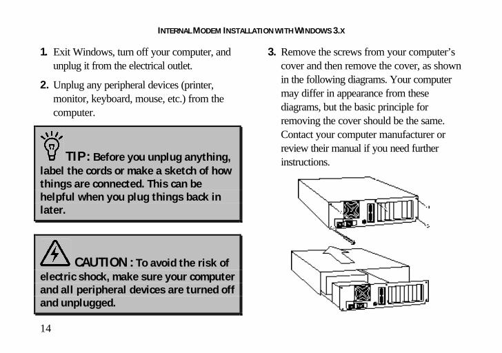
1. Exit Windows, turn off your computer, andunplug it from the electrical outlet.
2. Unplug any peripheral devices (printer,monitor, keyboard, mouse, etc.) from thecomputer.
TIP: Before you unplug anything,label the cords or make a sketch of howthings are connected. This can behelpful when you plug things back inlater.
CAUTION : To avoid the risk ofelectric shock, make sure your computerand all peripheral devices are turned offand unplugged.
3. Remove the screws from your computer’scover and then remove the cover, as shownin the following diagrams. Your computermay differ in appearance from thesediagrams, but the basic principle forremoving the cover should be the same.Contact your computer manufacturer orreview their manual if you need furtherinstructions.

INTERNAL MODEM INSTALLATION WITH WINDOWS 3.X
15
4. Find an empty ISA expansion slot atleast as long as the gold edge of yourmodem. (ISA slots have black plasticgrooves lined with silver metal.)Unscrew and remove the expansionslot cover (the long narrow piece ofmetal that keeps dust from enteringthrough the opening perpendicular tothe slot). Be careful not to drop thescrew into the computer. You willneed it later to screw the modem intoplace.

INTERNAL MODEM INSTALLATION WITH WINDOWS 3.X
16
5. Holding the modem at each corner, with thegold edge facing the slot, push the modemdown as gently as possible until it snaps intothe expansion slot.
NOTE: The drawings showhorizontally aligned expansion slots.Some computers have verticallyaligned slots. The instructions applyto both styles.
You need to apply a little pressure to seatthe modem properly. Sometimes a gentleback-and-forth motion helps to fit themodem all the way into the slot. If you feelresistance, the modem may not be properlylined up with the slot. Do not force it intothe slot. Remove the modem and try again.
6. Once the modem is in place, fasten it firmlyinto place using the screw that you removedin step 4.

INTERNAL MODEM INSTALLATION WITH WINDOWS 3.X
17
7. Replace the computer’s cover and fasten itwith the screws you removed in step 3.
8. If you currently have a phone plugged intothe wall jack you plan to use for themodem, disconnect the phone’s cord fromthe jack.
WARNING : The phone jack youuse must be for an ANALOG phone line(the type found in most homes). Manyoffice buildings have digital phonelines. Be sure you know which type ofline you have. The modem will bedamaged if you use a digital phone line.
9. Plug one end of the phone cord that camewith the modem into the TELCO jack atthe rear of the modem. Plug the other endof the cord into the wall jack.
10. If you want to use a phone through thesame phone wall jack as the modem whenthe modem is not in use, plug your phone’scord into the modem’s PHONE jack.
NOTE: You cannot use the modemand a phone at the same time if theyshare the same telephone line.

INTERNAL MODEM INSTALLATION WITH WINDOWS 3.X
18
11. Plug the power cords, cables, andperipherals back into the computer and turnthe computer on.
12. Start Windows.
13. If you have your modem set toCOM1/IRQ4 or COM2/IRQ3, go to“Software Installation” on page 60. If youhave your modem configured to any othersetting, open Program Manager anddouble-click the Main icon.
14. Double-click the Control Panel icon.
15. Double-click the Ports icon.

INTERNAL MODEM INSTALLATION WITH WINDOWS 3.X
19
16. If it’s not already selected, click the COMport for your modem. Then click Settings.
17. Set the Baud Rate to the highest optionand Flow Control to Hardware.Then click Advanced.
18. In the Interrupt Request Line (IRQ)box, select the IRQ that ComTestrecommended.
19. Click OK.
20. You will see a screen prompting you torestart Windows. Click Restart Now.
INTERNAL MODEM INSTALLATION WITH WINDOWS 3.X
20
You are now ready to install the ConnectionsCD-ROM (included with your U.S. Roboticsmodem). Go to “Software Installation” on
page 60 for instructions on installing the CDand trying out your modem by registeringonline.

INTERNAL MODEM INSTALLATION WITH WINDOWS 95
21
You’ll need these items from your U.S.Robotics modem box:
modem phone cord
Connections CD
Plus:
a screwdriver (not included)
Plug and Play InstallationWith Windows 95, you may be able to simplyplug your new modem into your computer,power up, and be ready to work. Theoperating system should do all the work ofrecognizing the modem for you. This sectionwill guide you through this “Plug and Play”installation.

INTERNAL MODEM INSTALLATION WITH WINDOWS 95
22
How to Prepare for Plug andPlay InstallationCheck Your System’s Resources
Your modem is a Plug and Play device.Windows 95 can automatically identify a Plugand Play device and determine if your systemhas the resources necessary to support thedevice. However, Plug and Play will not workif you do not have resources available or ifdevices on your system are not reportingresource usage correctly. Here’s how you canverify that your system has the necessaryresources before installing the modem.1. Click the Windows 95 Start button, point
to Settings, and then click Control Panel.
2. Double-click the System icon.
3. When the “System Properties” screenappears, click the Device Manager tab.
4. Double-click Computer and the“Computer Properties” screen appears.
5. Select the Interrupt request (IRQ) optionat the top of the screen.
You will see the IRQs your system is currentlyusing. If IRQs 3, 4, 5, and 7 are being used,you need to free an IRQ before you begininstallation. This process involves moving adevice from the IRQ you want to use to adifferent (and usually higher) IRQ setting.Please read the documentation for (or contactthe manufacturer of) the device that iscurrently using the IRQ you want to usefor your modem to learn more about what

INTERNAL MODEM INSTALLATION WITH WINDOWS 95
23
you should do to free the IRQ for yourmodem.
Find Out Which Versionof Windows 95 You Have
1. Click OK.
2. Click the General tab.
3. Look at the system information. (Thisinformation is circled in the screen shown tothe right.) The number following the text“Microsoft Windows 95” will end with“950,” “950a,” or “950b.” This indicatesyour
version of Windows 95.
4. Write this number down for later reference.(Write it where you wrote your modem’sserial number. Then you’ll have bothnumbers on hand if you ever have to calltechnical support.)
5. Click OK.

INTERNAL MODEM INSTALLATION WITH WINDOWS 95
24
Check the Jumpers1. Touch an unpainted metal part of your
computer (the back is usually unpainted) todischarge static electricity. Static candamage your modem.
2. Take the modem out of its plastic bag.
3. Find the jumper shunts (small black plasticpieces) on the COM port and IRQ jumperpins on your modem. They should be inroughly the area indicated in the followingillustration.
When doing a “Plug and Play” installation,the jumper shunts should be placed so thatthey are hanging from single jumper pinsrather than on pairs of pins. Your modem’sjumper shunts should already be in this Plugand Play configuration. If they are not,move them so they are hanging as in thediagram on the next page.

INTERNAL MODEM INSTALLATION WITH WINDOWS 95
25
NOTE: If you need to move theshunts, grasp them with a tweezers or aneedle-nosed pliers. DO NOT grasp toofirmly, however, or you may crush theshunts. If a shunt seems stuck, trygently rocking it back and forth as youlift.
INTERNAL MODEM INSTALLATION WITH WINDOWS 95
26
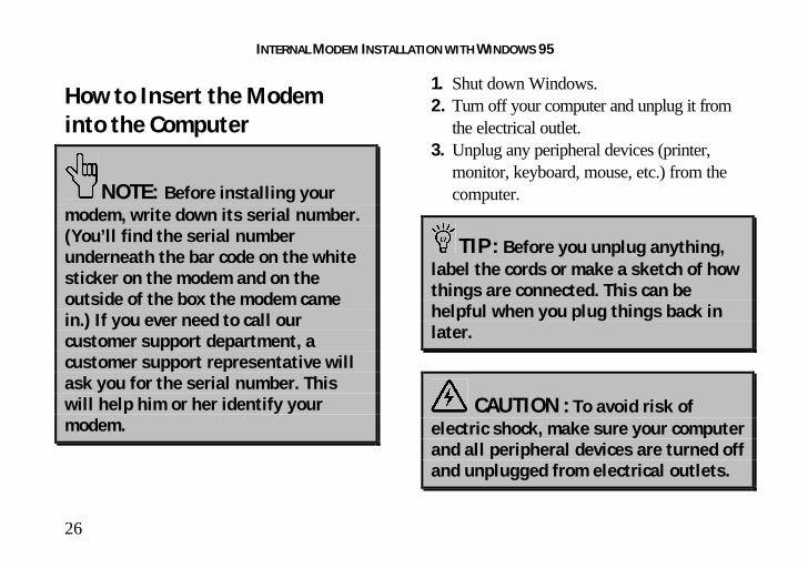
How to Insert the Modeminto the Computer
NOTE: Before installing yourmodem, write down its serial number.(You’ll find the serial numberunderneath the bar code on the whitesticker on the modem and on theoutside of the box the modem camein.) If you ever need to call ourcustomer support department, acustomer support representative willask you for the serial number. Thiswill help him or her identify yourmodem.
1. Shut down Windows.2. Turn off your computer and unplug it from
the electrical outlet.3. Unplug any peripheral devices (printer,
monitor, keyboard, mouse, etc.) from thecomputer.
TIP: Before you unplug anything,label the cords or make a sketch of howthings are connected. This can behelpful when you plug things back inlater.
CAUTION : To avoid risk ofelectric shock, make sure your computerand all peripheral devices are turned offand unplugged from electrical outlets.

INTERNAL MODEM INSTALLATION WITH WINDOWS 95
27
4. Remove the screws from your computer’scover and then remove the cover, as shownin the following diagrams. Your computermay differ in appearance from thesediagrams, but the basic principle forremoving the cover should be the same.Contact your computer manufacturer orreview their manual if you need furtherinstructions.
5. Find an empty ISA expansion slot that’s atleast as long as the gold edge of yourmodem. (ISA slots are black plasticgrooves lined with silver metal.) Unscrewand remove the expansion slot cover (thelong narrow piece of metal that keeps dustfrom entering through the openingperpendicular to the slot). Be careful not todrop the screw into the computer. You willneed it later to screw the modem into place.

INTERNAL MODEM INSTALLATION WITH WINDOWS 95
28
6. Holding the modem at each corner, with thegold edge facing the slot, push the modemdown as gently as possible until it snaps intothe expansion slot.
NOTE: The diagram on the leftshows horizontally aligned expansionslots. Some computers have verticallyaligned slots. The instructions applyto both styles.
You need to apply a little pressure to seatthe modem properly. Sometimes a gentleback-and-forth motion helps fit the modemall the way into the slot. If you feelresistance, the modem may not be properlylined up with the slot. Do not force it intothe slot. Remove the modem and try again.

INTERNAL MODEM INSTALLATION WITH WINDOWS 95
29
7. Once the modem is in the slot, screw themodem firmly into place using the screwthat you removed in step 5.
8. Replace the computer’s cover and fasten itwith the screws you removed in step 4.
9. Locate the wall jack you plan to use for themodem. If you have a phone plugged intothis jack, disconnect the phone’s cord fromthe jack.
WARNING : The phone jack youuse must be for an ANALOG phone line(the type found in most homes). Manyoffice buildings have digital phonelines. Be sure you know which type ofline you have. The modem will bedamaged if you use a digital phone line.
10. Plug one end of the phone cord included withthe modem into the TELCO jack at the rear ofthe modem. Plug the other end of the cable intothe wall jack.

INTERNAL MODEM INSTALLATION WITH WINDOWS 95
30
11. If you wish to use a phone through the samephone wall jack as the modem when themodem is not in use, plug your phone’s cordinto the modem’s PHONE jack.
NOTE: You cannot use the modemand a phone at the same time if theyshare the same telephone line.
12. Plug the power cords, cables, andperipherals back into the computer and turnthe computer on.

INTERNAL MODEM INSTALLATION WITH WINDOWS 95
31
How to Move Throughthe Screens You SeeWhen Windows Restarts
If you have Windows 95 version 950b,go to the instructions on page 36.
If you have Windows 95 version 950or 950a, continue here:
1. When Windows 95 restarts, it shoulddetect the modem. If it does, you will seethe following screen.
Click Driver from disk provided byhardware manufacturer. Then click OK.
NOTE: If this screen does notappear, go to “Plug and Play Does NotDetect Your Modem” on page 103.

INTERNAL MODEM INSTALLATION WITH WINDOWS 95
32
2. When you see this screen, insert theConnections CD into your CD-ROMdrive and type D:\ to replace the A:\.
NOTE: If your CD-ROM drivehas a different letter name, type thatletter instead of D.
Click OK. Windows will load the modem’sdrivers.
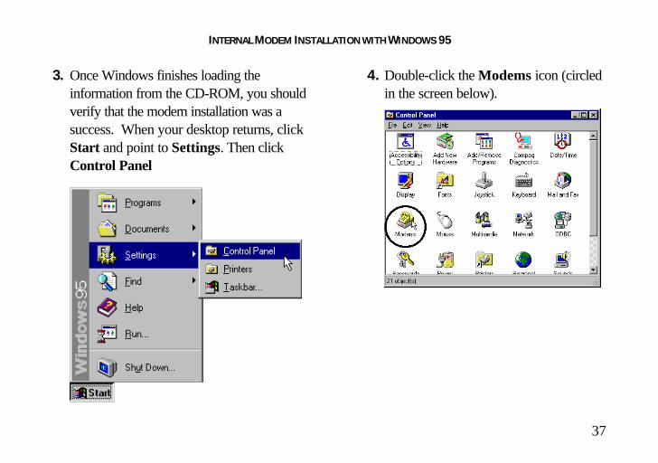
3. Once Windows finishes loading theinformation from the CD-ROM, you shouldverify that the modem installation was asuccess. When your desktop returns, clickthe Windows Start button and point toSettings. Then click Control Panel.

INTERNAL MODEM INSTALLATION WITH WINDOWS 95
33
4. Double-click the Modems icon (circled inthe screen image below).
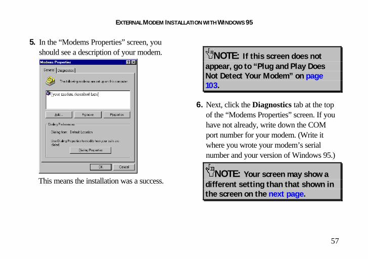
5. In the “Modems Properties” screen, youshould see a description for your modem.
This means the installation wasa success.
NOTE: If this screen does notappear, go to “Plug and Play DoesNot Detect Your Modem” on page103.

INTERNAL MODEM INSTALLATION WITH WINDOWS 95
34
6. Next, click the Diagnostics tab at the topof the “Modems Properties” screen. If youhave not already, write down the COMport number for your modem. (Write itwhere you wrote your modem’s serialnumber and your version of Windows 95.)
NOTE: Your screen may show adifferent setting than that shown inthe screen to the right.
You will need to know this setting when youinstall your communications software.
Click the COM port to highlight it onscreen.
7. Click More Info….

INTERNAL MODEM INSTALLATION WITH WINDOWS 95
35
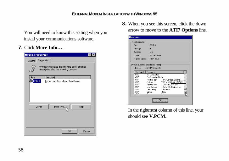
8. When you see this screen, click the downarrow to move to the ATI7 Options line.
In the rightmost column of this line, yourshould see V.PCM.
9. Click OK.
You are now ready to install the ConnectionsCD-ROM (included with your U.S. Roboticsmodem). Go to “Software Installation” onpage 60 for instructions on installing theConnections CD and trying out your modemby registering online.

INTERNAL MODEM INSTALLATION WITH WINDOWS 95
36
If You Have Windows 95 Version 950b
1. When Windows restarts, it should detect themodem, and you should see a screen likethe one below.
Insert the Connections CDand click Next.
NOTE: If this screen does notappear, go to “Plug and PlayDoes Not Detect Your Modem”on page 103.
2. When you see the following screen,click Finish.
INTERNAL MODEM INSTALLATION WITH WINDOWS 95
37
3. Once Windows finishes loading theinformation from the CD-ROM, you shouldverify that the modem installation was asuccess. When your desktop returns, clickStart and point to Settings. Then clickControl Panel
4. Double-click the Modems icon (circledin the screen below).

INTERNAL MODEM INSTALLATION WITH WINDOWS 95
38
5. In the “Modems Properties” screen, youshould see a description of your modem.
This means the installation was a success.
NOTE: If this screen does notappear, go to “Plug and Play DoesNot Detect Your Modem” on page103.
6. Next, click the Diagnostics tab at the topof the “Modems Properties” screen. If youhave not already, write down the COMport number for your modem. (Write itwhere you wrote your modem’s serialnumber and your version of Windows 95.)
NOTE: Your screen may show adifferent setting than that shown inthe screen on the next page.
You will need to know this setting when youinstall your communications software.

INTERNAL MODEM INSTALLATION WITH WINDOWS 95
39
7. Click the Port and then click More Info….
8. When you see screen to the right, click thedown arrow to move to the ATI7 Options line.
In the rightmost column of this line, yourshould see V.PCM.
INTERNAL MODEM INSTALLATION WITH WINDOWS 95
40
9. Click OK.You are now ready to install the ConnectionsCD-ROM (included with your U.S. Roboticsmodem). Go to “Software Installation” onpage 60 for instructions on installing theConnections CD and trying out your modemby registering online.

EXTERNAL MODEM INSTALLATION WITH WINDOWS 3.X
41
You’ll need these items from yourU.S. Robotics modem box:
modem phone cord
Connections CD power adapter
Plus:
Serial modem cable. (Not included. See nextcolumn.)
How to Determine WhichSerial Cable to BuyBefore you can begin installation, you need topurchase an RS-232 serial modem cable. Thissection will help you to determine which serialmodem cable to purchase.
NOTE: Your computer’s rear panelmay not be identical to the followingdiagrams. However, you should look forconnectors that match the enlargedportions of the following diagrams. Ifyou cannot locate the proper connector,refer to your computer’s manual.

EXTERNAL MODEM INSTALLATION WITH WINDOWS 3.X
42
If your PC's serial connector looks like this, youneed a shielded serial modem cable with a 25-pin female to 25-pin male connector (also calleda “DB25/DB25M cable”):
If your PC's serial connector looks like this, youneed a shielded serial modem cable with a 9-pinfemale to 25-pin male connector (also called a“DB9/DB25M cable”):
How to Connect the Modemto the Computer1. Turn off your computer and any attached
devices, such as a printer.
2. Connect the serial cable to the modem andto the computer. When looking for theserial port label on the back of yourcomputer, look for ports labeled COM,MODEM, RS-232, or SERIAL.DO NOT select AUX, GAME, LPT, orPARALLEL. (If your ports are not labeled,

EXTERNAL MODEM INSTALLATION WITH WINDOWS 3.X
43
refer to your computer manufacturer’smanual for guidance.)
3. Plug the power adapter into a standard walloutlet and insert its plug into the power jackon the modem (labeled with a poweradapter icon on the bottom of the case).
4. Plug one end of the phone cord into theTELCO jack (labeled with a wall plug iconon the bottom of the case) and the otherend into a phone wall jack.
WARNING : The phone jack youuse must be for an ANALOG phone line(the type found in most homes). Manyoffice buildings have digital phonelines. Be sure you know which type ofline you have. The modem will bedamaged if you use a digital phone line.
5. If you wish to use your modem and phonethrough the same phone wall jack, plugyour phone's cord into the modem's phonejack (labeled with a phone icon on thebottom of the case).
NOTE: You cannot use the modemand a phone at the same time if theyshare the same telephone line.

EXTERNAL MODEM INSTALLATION WITH WINDOWS 3.X
44
6. Turn on your modem (the power switch islocated on the front panel).
7. Turn on your computer and peripherals.
8. Start Windows.
You are now ready to install the ConnectionsCD-ROM (included with your U.S. Roboticsmodem). Go to “Software Installation” onpage 60 for instructions on installing theConnections CD and trying out your modemby registering online.

EXTERNAL MODEM INSTALLATION WITH WINDOWS 95
45
You’ll need these items from yourU.S. Robotics modem box:
modem phone cord
Connections CD power adapter
Plus:
Serial modem cable. (Not included. See nextcolumn.)
How to Determine WhichSerial Cable to BuyBefore you can begin installation, you need topurchase an RS-232 serial modem cable. Thissection will help you to determine which serialmodem cable to purchase.
NOTE: Your computer’s rear panelmay not be identical to the followingdiagrams. However, you should look forconnectors that match the enlargedportions of the following diagrams. Ifyou cannot locate the proper connector,refer to your computer’s manual.

EXTERNAL MODEM INSTALLATION WITH WINDOWS 95
46
If your PC's serial connector looks like this,you need a shielded serial modem cable with a25-pin female to 25-pin male connector (alsocalled a “DB25/DB25M cable”):
If your PC's serial connector looks like this,you need a shielded serial modem cable with a9-pin female to 25-pin male connector (alsocalled a “DB9/DB25M cable”):
EXTERNAL MODEM INSTALLATION WITH WINDOWS 95
47
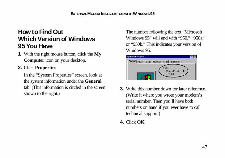
How to Find OutWhich Version of Windows95 You Have1. With the right mouse button, click the My
Computer icon on your desktop.
2. Click Properties.
In the “System Properties” screen, look atthe system information under the Generaltab. (This information is circled in the screenshown to the right.)
The number following the text “MicrosoftWindows 95” will end with “950,” “950a,”or “950b.” This indicates your version ofWindows 95.
3. Write this number down for later reference.(Write it where you wrote your modem’sserial number. Then you’ll have bothnumbers on hand if you ever have to calltechnical support.)
4. Click OK.
EXTERNAL MODEM INSTALLATION WITH WINDOWS 95
48
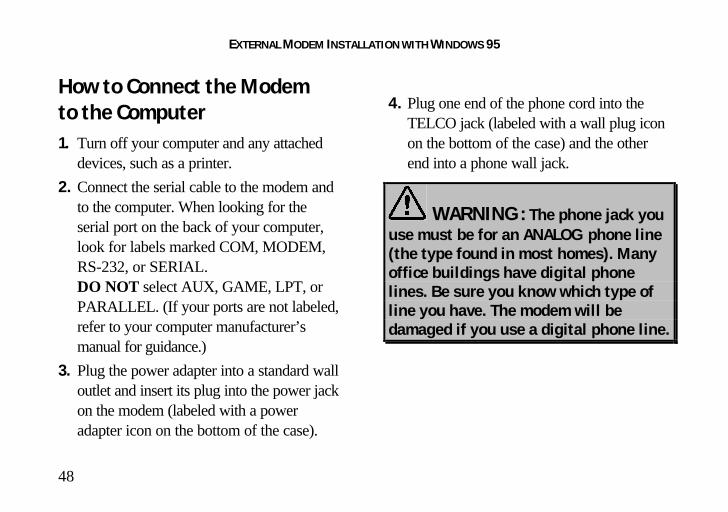
How to Connect the Modemto the Computer1. Turn off your computer and any attached
devices, such as a printer.
2. Connect the serial cable to the modem andto the computer. When looking for theserial port on the back of your computer,look for labels marked COM, MODEM,RS-232, or SERIAL.DO NOT select AUX, GAME, LPT, orPARALLEL. (If your ports are not labeled,refer to your computer manufacturer’smanual for guidance.)
3. Plug the power adapter into a standard walloutlet and insert its plug into the power jackon the modem (labeled with a poweradapter icon on the bottom of the case).
4. Plug one end of the phone cord into theTELCO jack (labeled with a wall plug iconon the bottom of the case) and the otherend into a phone wall jack.
WARNING : The phone jack youuse must be for an ANALOG phone line(the type found in most homes). Manyoffice buildings have digital phonelines. Be sure you know which type ofline you have. The modem will bedamaged if you use a digital phone line.

EXTERNAL MODEM INSTALLATION WITH WINDOWS 95
49
5. If you wish to use your modem and phonethrough the same phone wall jack, plugyour phone's cord into the modem's phonejack (labeled with a phone icon on thebottom of the case).
NOTE: You can not use the modemand phone at the same time if theyshare the same telephone line.
6. Turn on your modem (the power switch islocated on the front panel).
7. Turn on your computer and peripherals.

EXTERNAL MODEM INSTALLATION WITH WINDOWS 95
50
How to Move Throughthe Screens You SeeWhen Windows Restarts
If you have Windows 95 version 950b,go to the instructions on page 55.
If you have Windows 95 version 950or 950a, continue here:
1. When Windows 95 restarts, it shoulddetect the modem. If it does, you will seethe following screen.
Click Driver from disk provided byhardware manufacturer. Then click OK.
NOTE: If this screen does notappear, go to “Plug and Play Does NotDetect Your Modem” on page 103.
EXTERNAL MODEM INSTALLATION WITH WINDOWS 95
51
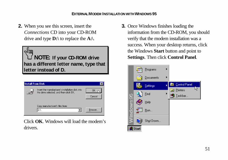
2. When you see this screen, insert theConnections CD into your CD-ROMdrive and type D:\ to replace the A:\.
NOTE: If your CD-ROM drivehas a different letter name, type thatletter instead of D.
Click OK. Windows will load the modem’sdrivers.
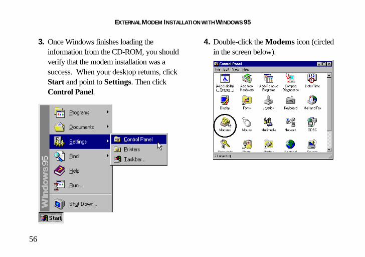
3. Once Windows finishes loading theinformation from the CD-ROM, you shouldverify that the modem installation was asuccess. When your desktop returns, clickthe Windows Start button and point toSettings. Then click Control Panel.
EXTERNAL MODEM INSTALLATION WITH WINDOWS 95
52
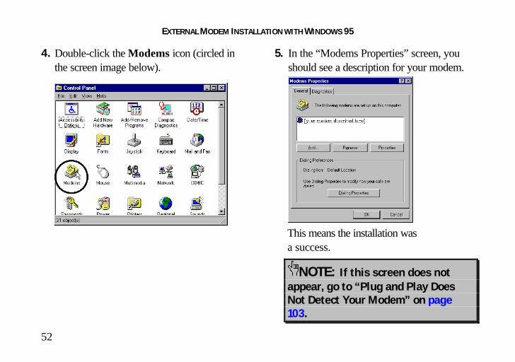
4. Double-click the Modems icon (circled inthe screen image below).
5. In the “Modems Properties” screen, youshould see a description for your modem.
This means the installation wasa success.
NOTE: If this screen does notappear, go to “Plug and Play DoesNot Detect Your Modem” on page103.
EXTERNAL MODEM INSTALLATION WITH WINDOWS 95
53
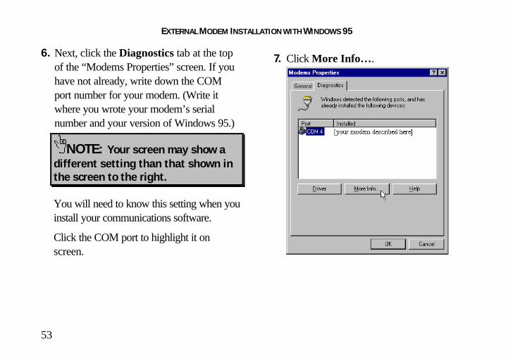
6. Next, click the Diagnostics tab at the topof the “Modems Properties” screen. If youhave not already, write down the COMport number for your modem. (Write itwhere you wrote your modem’s serialnumber and your version of Windows 95.)
NOTE: Your screen may show adifferent setting than that shown inthe screen to the right.
You will need to know this setting when youinstall your communications software.
Click the COM port to highlight it onscreen.
7. Click More Info….
EXTERNAL MODEM INSTALLATION WITH WINDOWS 95
54
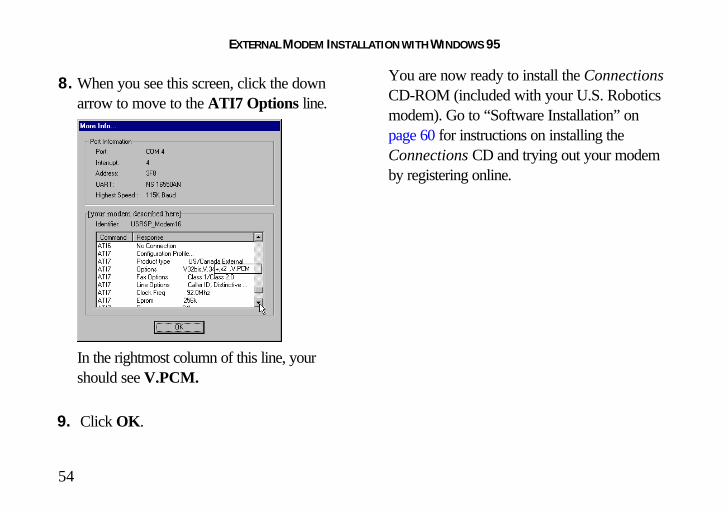
8. When you see this screen, click the downarrow to move to the ATI7 Options line.
In the rightmost column of this line, yourshould see V.PCM.
9. Click OK.
You are now ready to install the ConnectionsCD-ROM (included with your U.S. Roboticsmodem). Go to “Software Installation” onpage 60 for instructions on installing theConnections CD and trying out your modemby registering online.

EXTERNAL MODEM INSTALLATION WITH WINDOWS 95
55
If You Have Windows 95 Version 950b
1. When Windows restarts, it should detect themodem, and you should see a screen likethe one below.
Insert the Connections CDand click Next.
NOTE: If this screen does notappear, go to “Plug and PlayDoes Not Detect Your Modem”on page 103.
2. When you see the following screen,click Finish.
EXTERNAL MODEM INSTALLATION WITH WINDOWS 95
56
3. Once Windows finishes loading theinformation from the CD-ROM, you shouldverify that the modem installation was asuccess. When your desktop returns, clickStart and point to Settings. Then clickControl Panel.
4. Double-click the Modems icon (circledin the screen below).
EXTERNAL MODEM INSTALLATION WITH WINDOWS 95
57
5. In the “Modems Properties” screen, youshould see a description of your modem.
This means the installation was a success.
NOTE: If this screen does notappear, go to “Plug and Play DoesNot Detect Your Modem” on page103.
6. Next, click the Diagnostics tab at the topof the “Modems Properties” screen. If youhave not already, write down the COMport number for your modem. (Write itwhere you wrote your modem’s serialnumber and your version of Windows 95.)
NOTE: Your screen may show adifferent setting than that shown inthe screen on the next page.
EXTERNAL MODEM INSTALLATION WITH WINDOWS 95
58
You will need to know this setting when youinstall your communications software.
7. Click More Info….
8. When you see this screen, click the downarrow to move to the ATI7 Options line.
In the rightmost column of this line, yourshould see V.PCM.

EXTERNAL MODEM INSTALLATION WITH WINDOWS 95
59
9. Click OK.You are now ready to install the ConnectionsCD-ROM (included with your U.S. Roboticsmodem). Go to “Software Installation” onpage 60 for instructions on installing theConnections CD and trying out your modemby registering online.

SOFTWARE INSTALLATION
60
This section tells you how to startthe U.S. Robotics Setup Wizard on theConnections™ CD.
The Wizard will guide you through installing theConnections program group and testing yourmodem by registering online.
Follow this section’s instructions to start theWizard, and then simply follow the Wizard’son-screen instructions.
NOTE: The following instructionsapply to Windows 3.x and Windows 95users. However, only Windows 95screens are shown.

SOFTWARE INSTALLATION
61
Starting the Wizard1. From the Windows 95 desktop, click the
Start button and then click Run.
2. In the text box, type D:\setup.exe.(If your CD-ROM drive has a letter nameother than D, type that letter in place of D.)
Click OK.
3. Follow the on-screen instructions to run theWizard.

SOFTWARE INSTALLATION
62
After running the Wizard, you’ll be given theoption to explore the Connections CD.
When you want to use the Connections CD:
1. Insert the CD into your CD-ROM drive.
2. Click Start, point to Programs, point toU.S. Robotics Connections, and thenclick Connections.
Installing the RapidComm™Fax/Data SoftwareThe Connections CD contains theRapidComm fax/data communicationsprogram. You can use this program to transferfaxes and data files to remote modems.
NOTE: If you have an olderversion of RapidComm installed on yoursystem, uninstall it before continuing.To start the uninstall: Windows 3.xusers: Click on the Uninstall icon in theRapidComm program group. Windows95 users: Double-click on theAdd/Remove Programs icon in theControl Panel.
SOFTWARE INSTALLATION
63
Once you’ve run the Setup Wizard, you caninstall RapidComm. (The Setup Wizard doesnot install RapidComm.)
To start the RapidComm installation:
1. Start the Connections CD (follow theinstructions on the previous page).
2. On the main Connections menu, click theBusiness & Productivity button.
3. Click the RapidComm button.
4. Follow the on-screen instructions to finishthe installation.
The CD also contains an electronic usermanual for RapidComm.
Congratulations —you arenow ready to start usingyour U.S. Robotics modem!
INSTALLING OTHER FAX/DATA SOFTWARE
64
You can use fax/data software other thanRapidComm (the fax/data software on theConnections CD). Your modem wasdesigned for and tested using a wide range ofcommunications software packages. Thissection will guide you through some of thedetails you may need to know when installingother communications software packages.
Type of ModemMost communications software programs willask you to select the type of modem you areusing. Select a U.S. Robotics Sportster highspeed modem. If that selection is not listed,pick Courier Dual Standard, V.32bis, orV.34.
KEY POINT: Refer to your softwaremanual for the program’s installationinstructions. The software’s installationprogram will ask you questions about themodem you are using.
Initialization StringFor hardware flow control, a fixed serial port rateand full result codes, type AT&F1 and pressENTER. If you must use software flow control,type AT&F2 and press ENTER.
NOTE: If you use the Modem Stationprogram to configure your modem, youmust use ATZ for the initialization string.
.

INSTALLING OTHER FAX/DATA SOFTWARE
65
Flow Control• For hardware flow control (highly
recommended), select RTS/CTS.• For software flow control, select
XON/XOFF.
NOTE: You may need to disable thetype of flow control (hardware orsoftware) that you are not using.
UART (External Modems)If you are running Windows 3.x or you haveupgraded your system from Windows 3.x toWindows 95, you can run MSD to determineyour UART setting. In DOS, type MSD at theWindows directory prompt and then pressENTER. Follow the on-screen instructions toaccess the COM port settings panel. In thispanel you should find the
UART chip used. Match the UART type listedin MSD with the serial rate listed in the chartbelow. Select this serial rate (sometimes calledthe “port rate”) in any communicationssoftware you use.
Select thisIf this is your UART... serial rate16550* 115.2 or
57.6 kbps
16450 38.4 kbps
8250 19.2 kbps
*All U.S. Robotics internal modems have a 16550UART.
NOTE: DO NOT select a 28,800,14,400, or 12,000 bps serial port rate, ifoffered. Your modem will NOT workcorrectly with any of these settings. Fixor lock the serial port (baud) rate (if it’sreferred to as autobaud, select OFF).

USING MODEM STATION
66
What Does Modem StationDo?♦ Modem Station provides a simple to use
interface that makes communicating withyour modem easy.
♦ Modem Station allows you to point andclick your way through configuration.
♦ Modem Station can automatically detectyour modem and provide you with all thetechnical information you need, wheneveryou need it!
Why Modem Station?♦ Modem commands can be confusing and
difficult to memorize.♦ Communications software often requires
technical information about your modem.
♦ You may want to “tweak” your modem for
optimum performance.
Installing Modem StationIf you did not install Modem Station when youfirst installed the Connections CD, pleasefollow these instructions.
1. Insert the Connections CD into your CD-ROM drive.
2. Double-click the My Computer icon onyour desktop.
3. Double-click the CD-ROM icon.
4. Double-click the usrtools folder.
5. Double-click the umssetup icon.

USING MODEM STATION
67
6. You will be asked whether you wish toinstall Modem Station. Click Yes.
7. Wait a few moments for the InstallationWizard to load.
8. After reading the information on the“Welcome” screen, click Next.
9. When you see this screen, click Next toaccept the default directory or clickBrowse to change directories.

USING MODEM STATION
68
10. Click Next on the following screen toaccept the default program folder. You canplace Modem Station in an existing folderby selecting one from the list.
11. When you see the following screen, clickFinish to complete the installation.
If this is the first time you’ve installedModem Station, you may be asked torestart your computer.

USING MODEM STATION
69
Starting Modem Station1. If you didn’t start Modem Station from the
Setup program, please start it now.
2. Click Windows Start button and then pointto Programs. Click U.S. RoboticsModem Station (or the folder youselected during installation).
3. Click the Modem Station icon. This bringsup the main menu.
The main menu gives you direct access tothe following options:
DETECT NEW MODEMS
This option detects US Robotics modemsinstalled on your system and shows whatCOM port they are using. Click this option ifyou are running Modem Station for the firsttime, if you are changing modems, or if yousimply need to know what port your modem isusing.
TERMINAL
Terminal allows you to send commandsdirectly to your modem and displays theresponses. You can use Terminal to dial upBBSs. In addition, you can configure yourmodem using Terminal. However, it is mucheasier to use the Modem Configurator.

USING MODEM STATION
70
MODEM CONFIGURATORModem Configurator provides an easy-to-useinterface for entering hard-to-remembercommands. Use Modem Configurator fortroubleshooting, initial configuration, and tuningyour modem for optimum performance. Usingthe options available in Modem Configurator,you can control nearly every aspect of yourmodem’s performance. We will discussModem Configurator’s options in more detailin later sections.
ABOUT
The About option provides copyright andversion information.
CONTACT/SUPPORTThis option details how to get in touch with3Com.
TIP: For your convenience, weprovide many on-line supportavenues. For specific questions,our fax-on-demand service is agood place to start. You candownload FAQs, software, and helpfiles from our Web sites and BBS,or receive individualized supportvia [email protected]. Type 0000 (4zeroes) in the subject line of youre-mail.

USING MODEM STATION
71
Using Detect New Modems1. Click Detect New Modems to bring up
the following screen.
The screen consists of four columns, one foreach possible COM port on a PC. Youcan scan a specific port(s) by selecting thecheckbox for that port.
2. Click Scan to have Modem Station checkfor installed modems. This may take a fewmoments.
3. When the scan finishes, you will see thefollowing display. Your display may differdepending on the type and number ofmodems installed.
If your modem is installed and configuredcorrectly, Modem Station will find the

USING MODEM STATION
72
modem and display make and modelinformation under the assigned port. Allcurrently active ports should display “PortOK” under the heading. If a port displays a“Port Error”, it usually means that the port isdisabled in system setup.
NOTE: Different systems andBIOSes use different methods ofdisabling COM ports. As a result,we cannot provide support fordisabling/enabling COM ports.Please refer to your system’sdocumentation or contact themanufacturer of your system forfurther information.
If you look at the information for the port yourmodem is using, you will see three buttons.These allow you to access Terminal and
Modem Configurator without going back tothe main menu. Extended Information providesdetailed information about your modem,previous connections, firmware dates, etc. Thisnext section details using the Terminal option.
Using TerminalYou can access Terminal from either the Mainmenu or the Detect New Modems screen.Clicking Terminal brings up the Terminalwindow.
In addition to allowing direct entry of modemcommands, the Terminal window also allows

USING MODEM STATION
73
you to dial into Bulletin Boards, listing services,and other online services.
NOTE: Modem Station’sTerminal window is providedprimarily for troubleshootingconvenience. If you frequently useBBSs, you will probably want touse a separate, full-featuredTerminal program such as thatprovided in our RapidCommsoftware.
On the lower part of the Terminal screen, youwill see the COM port your modem iscurrently using. To select another modem,simply click on the arrow and select thatmodem’s assigned port.
To the right of the port settings are the portspeed settings. Port speed is the speed atwhich your computer sends data to the

USING MODEM STATION
74
modem. We will discuss port speed settings indetail later in this section.
Terminal includes a basic auto dialer.
To have Terminal dial a number for you, clickDial to bring up the “Dial” screen.
You need to tell the Dialer a few things aboutyour phone system, such as whether it usestone or pulse dialing, what digit, if any, youneed to dial to get an outside line, and whetherthe dialer should wait between dialing that digitand the rest of the number. Once you providethis information, simply enter the phone numberas if you were dialing a telephone. Click DialNow to dial the number.
You can end a call by clicking Hang Up at thebottom of the screen.
When you are finished using Terminal, clickExit to return to the screen you accessed itfrom.
Using Modem ConfiguratorYou can access Modem Configurator fromeither the Main menu or the Detect NewModems screen.
Click Modem Configurator to bring up thismenu.

USING MODEM STATION
75
The Modem Configurator menu gives youaccess to the following options:
Data Control
This is the “Data Control” screen.
The “Data Control” screen allows you toassign the following basic communicationssettings:
♦ PORT SPEED♦ PARITY♦ STOP BITS♦ WORD LENGTH
♦ FLOW CONTROL♦ SERIAL PORT RATE
For information on using these settings, pleaserefer to the “Glossary” at the back of thismanual.
Click Help for quick definitions of theterminology used in this screen.
In the upper left-hand corner of the screen,you will see the data control commandscurrently in use.
Once you have entered the Data Controlsettings, click Save to Modem. This storesthe settings so that you do not have to re-enterthem.
This screen also displays the default DIPswitch settings.

USING MODEM STATION
76
TECHNICAL STUFF: DIPswitches are tiny switches thatcontrol a few basic functions onsome external modems. Onmodems without DIP switches,these functions are handled bymodem commands.
Click Exit to return to the ModemConfigurator menu.
CONNECTION CONTROLThis is where you adjust your modem’sconnection and transmission settings.
Click Connection Control to bring up thisscreen.
In the upper left hand corner of this screen,you will find the current Connection Controlsettings.
USING MODEM STATION
77
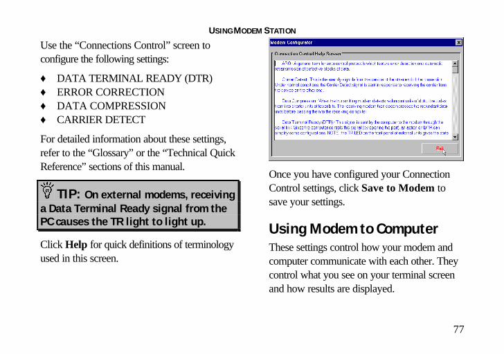
Use the “Connections Control” screen toconfigure the following settings:
♦ DATA TERMINAL READY (DTR)♦ ERROR CORRECTION♦ DATA COMPRESSION♦ CARRIER DETECT
For detailed information about these settings,refer to the “Glossary” or the “Technical QuickReference” sections of this manual.
TIP: On external modems, receivinga Data Terminal Ready signal from thePC causes the TR light to light up.
Click Help for quick definitions of terminologyused in this screen.
Once you have configured your ConnectionControl settings, click Save to Modem tosave your settings.
Using Modem to ComputerThese settings control how your modem andcomputer communicate with each other. Theycontrol what you see on your terminal screenand how results are displayed.

USING MODEM STATION
78
If you look in the upper left hand corner of thedisplay, you will see the commands currently inuse.
The “Modem to Computer” screen allows youto configure the following settings:
♦ LOCAL ECHO♦ RESULT CODES♦ RESULT CODE PREFERENCES
TIP: If you type ATDT and see‘AATTDDTT’ on your screen, it ispossible that both your software andmodem have Local Echo set to ‘ON’.Turn Local Echo ‘OFF’ on EITHER themodem or the software to solve thisproblem.
For details on using the commands in thisscreen, refer to the “Glossary” or “TechnicalQuick Reference” sections of this manual.
Click Help to see quick definitions ofterminology used in this screen.
This screen also includes a chart of the waysresult codes can be displayed. Click Codes toview a chart of the display options.
Once you configure your settings, click Saveto Modem to save your choices.

USING MODEM STATION
79
CONNECTION RATES
The “Connection Rates” screen allows you toconfigure modem speeds and protocols.
WARNING! Use cautionwhen changing connectionsettings. Improper settings maycause your modem to functionincorrectly, disconnect, or fail toconnect at all.
In the upper left hand corner of the screen youwill see the current connection commands.
This screen allows you to configure thefollowing settings:
♦ MODULATIONS♦ V.34 SYMBOL RATES♦ SPEEDS
Again, once you have selected your settings,click Save to Modem to save them.
When you are finished, click Exit to return tothe Modem Configurator menu.
Please refer to the main body of the manualand the “Glossary “for detailed informationabout the terminology and settings used in thisscreen.
Click Help for quick definitions of terminologyused in this screen.

USING MODEM STATION
80
DIALING/ANSWERING
The next screen allows you to adjust how yourmodem initiates and receives calls.
Using this screen, you can configure thefollowing dial settings:
♦ WAIT FOR CARRIER♦ AUTO-ANSWER # OF RINGS♦ SPEAKER OPERATION♦ DIALING METHOD♦ SPEAKER VOLUME
STORED NUMBERS
The “Stored Numbers” screen displays thephone numbers currently stored in yourmodem’s memory.
Use this screen to edit or add numbers storedin the modem’s memory.
To store a number in your modem’s memory,simply click in one of the entry boxes. Type inthe phone number exactly as you would dial it.Position Zero has a special feature. You canset your modem to automatically dial this

USING MODEM STATION
81
number when your computer is turned on orwhen it is reset. This is very useful if you areusing your modem with a “dumb terminal” orknow that you need to connect to a specificbulletin board or listing service.
You can change stored numbers by highlightingthem and then typing the new numbers in theirplace. Once you store your numbers, you candial them by entering a single command fromTerminal Mode:(for example: ATDS0, ATDS1, or ATDS2).
Your U.S. Robotics modem comes with onephone number already stored in Position 0. Ifyou haven’t changed the default, typingATDS0 will automatically dial the 3Com BBS.
Once you enter the numbers you wish to store,click Save to Modem to store them. ClickExit to return to the Main menu.
The last option, Restore Defaults, resets yourmodem to factory specifications. This option isavailable from many of the screens withinModem Station.
TIP: Restore Defaults will setyour modem back to factoryspecifications. It is a good place tostart when troubleshooting.
Using the ExtendedInformation ScreensThe “Extended Information” screens provideimportant and useful information about yourmodem.
We devote a separate section to the ExtendedInformation screens so that we can explain

USING MODEM STATION
82
what you’ll see (and why it is important to you)as fully as possible.
There are a series of commands used to obtaindetailed information from U.S. Roboticsmodems. Extended Information provides aconvenient way to get that importantinformation without memorizing the commands.
From the “Detect New Modems” screen, clickExtended Information.
The “Extended Information” screen providesaccess to the following information about yourmodem:
♦ ROM CHECKSUM♦ PRODUCT♦ ACTIVE PROFILE♦ STORED PROFILE♦ CONFIGURATION PROFILE♦ LINK DIAGNOSTICS♦ VxD CONFIGURATION
♦ DIAL/SECURITY
Winmodem users will have access to VxDinformation via these screens.
Courier users will have access to Dial/Securityinformation.
Click ROM Checksum to bring up thefollowing screen.
Technicians use the ROM Checksum to verifyinformation stored in the modem’s Read OnlyMemory. For information about the specific

USING MODEM STATION
83
modem you are using, click Product to bringup the next screen.
The “Product” screen displays the make andmodel of your modem.
Your modem is able to store twoconfigurations or “profiles.” Only one can beactive at any time.

USING MODEM STATION
84
To see information about the profile in use,click Active Profile to bring up the nextscreen.
This screen contains information about yourmodem’s current configuration. Starting fromthe top, you will see the make and model ofyour modem. Directly below that, you will seebasic commands currently in use followed bythe current connection settings.
The two lines below the connection settings arethe advanced commands currently in use.Below them is a display of the contents of the‘S-Registers’ for your modem. These registersare special programmable areas of yourmodem’s memory. They are used to storecommands that are too complex to be handledby the standard (or ‘AT’) commands. Justbelow that you will see the last number dialed.
The next option displays the “Stored Profile”screen. This screen shows the configurationstored in your modem’s NVRAM (specialprogrammable memory). Note that any storedphone numbers are displayed on this screen aswell.
The next two screens contain information thatour technical support representatives may needif you request support.
USING MODEM STATION
85
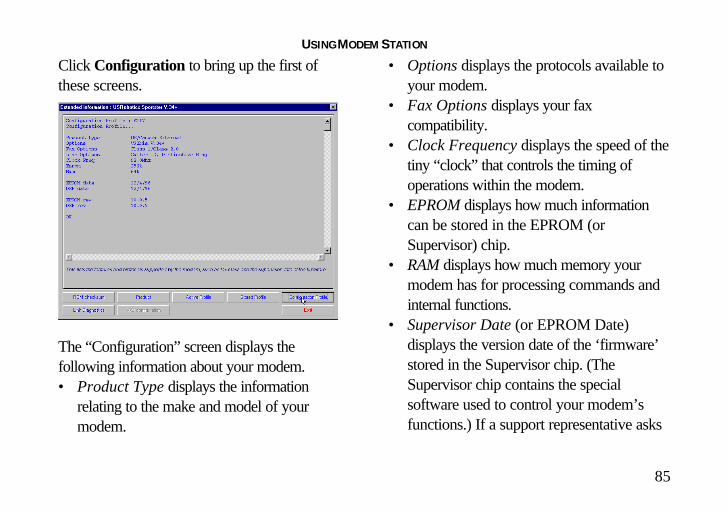
Click Configuration to bring up the first ofthese screens.
The “Configuration” screen displays thefollowing information about your modem.• Product Type displays the information
relating to the make and model of yourmodem.
• Options displays the protocols available toyour modem.
• Fax Options displays your faxcompatibility.
• Clock Frequency displays the speed of thetiny “clock” that controls the timing ofoperations within the modem.
• EPROM displays how much informationcan be stored in the EPROM (orSupervisor) chip.
• RAM displays how much memory yourmodem has for processing commands andinternal functions.
• Supervisor Date (or EPROM Date)displays the version date of the ‘firmware’stored in the Supervisor chip. (TheSupervisor chip contains the specialsoftware used to control your modem’sfunctions.) If a support representative asks

USING MODEM STATION
86
you for your Supervisor or EPROM date,look here.
• DSP Date is the date of the ‘firmware’ thatcontrols the DSP in your modem.
• Supervisor and DSP rev (or revisions) arethe equivalent of software version numbers.
• DAA Country displays the countries yourmodem is designed for. This is importantbecause phone systems andtelecommunications laws vary from countryto country.
Click Link Diagnostics to bring up the “LinkDiagnostics” screen.
The “Link Diagnostics” screen displaysstatistics about your last connection. Thisscreen is most often used as an aid indiagnosing connection failures, but it also canprovide information about connection speedsand phone line conditions.• Modulation displays the speed and type of
connection.• Carrier Frequency displays the electrical
frequency of the carrier signal.
USING MODEM STATION
87
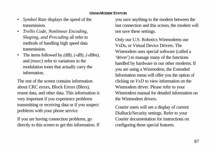
• Symbol Rate displays the speed of thetransmission.
• Trellis Code, Nonlinear Encoding,Shaping, and Precoding all refer tomethods of handling high speed datatransmission.
• The items followed by (dB), (-dB), (-dBm),and (msec) refer to variations in themodulation tones that actually carry theinformation.
The rest of the screen contains informationabout CRC errors, Block Errors (Blers),resent data, and other data. This information isvery important if you experience problemstransmitting or receiving data or if you suspectproblems with your phone service.
If you are having connection problems, godirectly to this screen to get this information. If
you save anything to the modem between thelast connection and this screen, the modem willnot save these settings.
Only our U.S. Robotics Winmodems useVxDs, or Virtual Device Drivers. TheWinmodem uses special software (called a‘driver’) to manage many of the functionshandled by hardware in our other modems. Ifyou are using a Winmodem, the ExtendedInformation menu will offer you the option ofclicking on VxD to view information on theWinmodem driver. Please refer to yourWinmodem manual for detailed information onthe Winmodem drivers.
Courier users will see a display of currentDialback/Security settings. Refer to yourCourier documentation for instructions onconfiguring these special features.

U.S. ROBOTICS MODEM UPDATE WIZARD
88
The Connections CD-ROM, which came withyour modem, includes the U.S. Robotics ModemUpdate Wizard. This software is designed toquickly update your modem to the newest code.
NOTE: You can also obtain thissoftware from our BBS (847-982-5092) orfrom our World Wide Web page(http://www.3Com.com/56k).
NOTE: Complete the instructions inthe “Software Installation” chapter(starting on page 60) before installing theModem Update Wizard.
NOTE: The following instructionsapply to Windows 3.x and Windows 95users. However, only Windows 95 screensare shown.

U.S. ROBOTICS MODEM UPDATE WIZARD
89
Installing the Wizard1. Insert the Connections CD into your
CD-ROM drive.2. Click Start and point to Programs.3. Point to U.S. Robotics Connections.4. Click Connections.
5. From the main Connections menu, click theCustomer Support button.
6. Click the Modem Update Wizard button.7. Follow the on-screen instructions to complete
the installation.
8. When you see the screen below, the setup iscomplete. Click OK.
NOTE: For more detailed instructions,see our World Wide Web page(http://www.3Com.com/56k).
Updating Your Modem1. Click Start. Point to Programs. Then point to
U.S. Robotics Modem Update Wizard.Finally, point to the Modem Update Wizardselection.
2. Follow the on-screen instructions to completethe update process.

TROUBLESHOOTING AND ONLINE HELP RESOURCES
90
PROBLEM:
The computer or software will notrecognize the modem.
Diagnosis:
If you are using an external modem, themodem might not be turned on.
Possible Solution:
Make sure the modem is turned on. Thepower switch is on top of external modems.The CS light on the front panel should be lit.(An internal modem should turn onautomatically when the computer is turnedon.)
Diagnosis:
You may not be entering modem commandsin the proper manner.
Possible Solution:
Type in all upper case (AT) or lower case(at).
Diagnosis:
If you are using an external modem, theCOM port may not be enabled.
Possible Solution:
Refer to your computer’s manual forinformation concerning enabling COM ports(usually involves altering the bios settings,motherboard jumpers, and the operatingsystem).
TROUBLESHOOTING AND ONLINE HELP RESOURCES
91
Diagnosis:
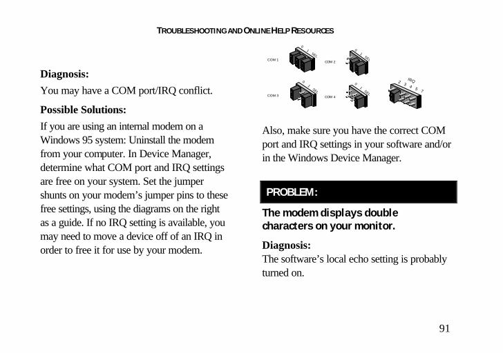
You may have a COM port/IRQ conflict.
Possible Solutions:
If you are using an internal modem on aWindows 95 system: Uninstall the modemfrom your computer. In Device Manager,determine what COM port and IRQ settingsare free on your system. Set the jumpershunts on your modem’s jumper pins to thesefree settings, using the diagrams on the rightas a guide. If no IRQ setting is available, youmay need to move a device off of an IRQ inorder to free it for use by your modem.
0 1 SEL COM 1
0 1 SEL COM 3
0 1 SELCOM 4
0 1 SELCOM 2
IRQ2 3 4 5 7
Also, make sure you have the correct COMport and IRQ settings in your software and/orin the Windows Device Manager.
PROBLEM:
The modem displays doublecharacters on your monitor.
Diagnosis:The software’s local echo setting is probablyturned on.

TROUBLESHOOTING AND ONLINE HELP RESOURCES
92
Possible Solution:Disable Local Echo in your software OR onyour modem (not both). You can turn thelocal echo off on the modem by typing ATE0and then pressing ENTER in your software’sterminal mode. To turn the local echo settingoff in the software, refer to its documentation.
PROBLEM:
The modem won’t go off hook to dialor doesn’t answer the phone.
Diagnosis:You may have plugged your modem’s phonecord into a digital line.
Possible Solution:
Plugging your modem’s phone cord into adigital phone line can damage the modem.Call your phone company if you are unsurewhether or not your phone line is digital.
TROUBLESHOOTING AND ONLINE HELP RESOURCES
93
Diagnosis:You may have plugged your modem’s phonecord into the wrong jack on the modem.
Possible Solution:Make sure the phone cord is plugged into ajack labeled with the word TELCO or a wallplug icon.
Diagnosis:You might have a bad phone cord connectionto your modem.
Possible Solution:The phone cord should be plugged into theTELCO jack on the modem and the wallphone jack. The phone cord should be nolonger than 12 feet in length. Use the phonecord included in your U.S. Robotics box ifpossible.
Diagnosis:The phone jack may have been wiredincorrectly.
Possible Solution:Contact the telephone company. Ask them tomake sure the tip and ring are on the insidepair of wires.
Diagnosis:You may have devices between the modemand the phone jack.
Possible Solution:There should be no line splitters, faxmachines, or other devices between themodem and the wall jack.

TROUBLESHOOTING AND ONLINE HELP RESOURCES
94
Diagnosis:You may have a poor line connection.
Possible Solution:Place the call again. Calls are routeddifferently each time. To verify a valid phoneconnection, enter RapidComm’s Terminalmode, type ATX3DT18479825092(the 3Com BBS), and press ENTER. Thisstring bypasses the dial tone, allowing aconnection if the modem is functioningproperly.
Diagnosis:If you have voice mail, your dial tone may bealtered when messages are waiting.
Possible Solution:Answer your voice mail to restore yournormal dial tone.
Diagnosis:Your software may not have auto answerenabled.
Possible Solution:Enable the auto answer feature. InRapidComm’s Terminal mode, typeATS0=1 and press ENTER.
NOTE: You need to enable autoanswer before every session unlessyou alter your software’sinitialization string to permanentlyenable auto answer.

TROUBLESHOOTING AND ONLINE HELP RESOURCES
95
PROBLEM:
Both modems sound like theyexchange carrier signals but fail toestablish a link.
Diagnosis:You may have a poor line connection.
Possible Solution:Try placing the call again. The phonecompany routes calls differently each time.To verify a valid phone connection, enterRapidComm’s Terminal mode and typeATX3DT18479855092 and press ENTER(the phone number is the 3Com BBS). Thisstring bypasses the dial tone, allowing aconnection if the modem is functioningproperly.
Diagnosis:The phone line might be wired incorrectly.
Possible Solution:Contact the telephone company and askthem to make sure the tip and ring are on theinside pair of wires.
PROBLEM:
Your modem cannot achieve a 56KInternet connection.
Diagnosis:Your modem is capable of receiving up to 56Kbps and sending up to 31.2 Kbps. Due toFCC regulations, receiving speeds are limitedto 53 Kbps. Actual speeds may vary. An
TROUBLESHOOTING AND ONLINE HELP RESOURCES
96
analog phone line compatible with the 56KITU standard or x2 technology, and anInternet provider or corporate host sitecompatible with the 56K ITU standard orx2™ technology are necessary for thesehigh-speed downloads.
Possible Solutions:Check http:// www.3com.com/56k for a listof ISPs that observe the 56K ITU standardand/or offer x2 technology.
Call your phone company to find out if yourphone line is compatible with the ITU-Tstandard for 56K and/ or isx2-compatible. You can also runthe U.S. Robotics Line Test utility todetermine if your line is compatible. To runthe test, visithttp:// www.3com.com/56k
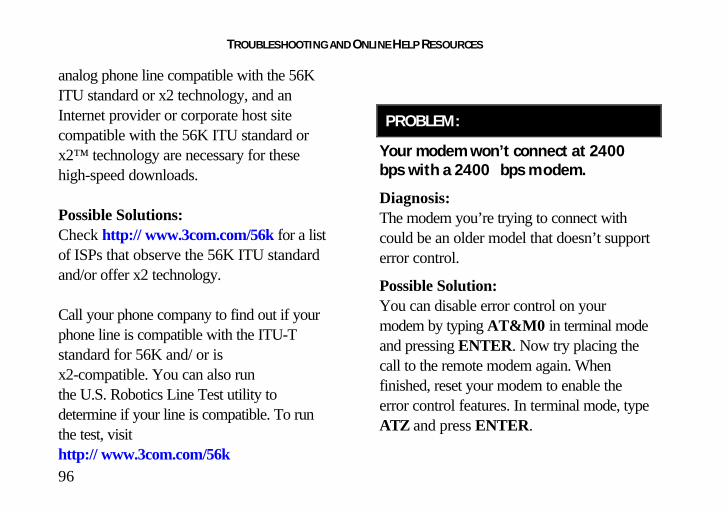
PROBLEM:
Your modem won’t connect at 2400bps with a 2400 bps m odem.
Diagnosis:The modem you’re trying to connect withcould be an older model that doesn’t supporterror control.
Possible Solution:You can disable error control on yourmodem by typing AT&M0 in terminal modeand pressing ENTER. Now try placing thecall to the remote modem again. Whenfinished, reset your modem to enable theerror control features. In terminal mode, typeATZ and press ENTER.

TROUBLESHOOTING AND ONLINE HELP RESOURCES
97
NOTE: ATZ4 or AT&F1 are oftenthe best reset strings, as theyrestore hardware flow controldefaults.
PROBLEM:
Your screen keeps displayingrandom garbage characters.
Diagnosis:You could have a conflict with the remotemodem’s settings for word length, parity, andstop bits.
Possible Solution:Set your modem’s word length, parity, andstop bits the same as the remote modem orBBS you are calling.
Diagnosis:Your software and modem might not be setto the same flow control settings.
Possible Solution:Make sure the software and modem have thesame flow control settings (hardware[RTS/CTS] and software [xon/xoff]). .
Diagnosis:The best flow control settings might not beenabled on your modem.

TROUBLESHOOTING AND ONLINE HELP RESOURCES
98
Possible Solution:In terminal mode, type AT&F1 and pressENTER to set hardware flow control.
PROBLEM:
Your commun ications software isreporting many cyclic redundancycheck (CRC) errors and lowcharacters per se cond (CPS).
Diagnosis:You may have a bad phone line.
Possible Solution:Try placing the call again. The phonecompany routes calls differently each time.
Diagnosis:Optimum flow control settings may not beenabled on your modem.
Possible Solution:In terminal mode, type AT&F1 and pressENTER to set hardware flow control.
Diagnosis:If your communications program isDOS-based, you’re running it underWindows, and other software is running,conflicts between programs may be causingthe CRC errors.
Possible Solution:Close every program but the communicationsprogram.
TROUBLESHOOTING AND ONLINE HELP RESOURCES
99
Diagnosis:The serial port rate in your communicationssoftware may be set too high for yourmodem’s UART or your area’s phone lines.
Possible Solution:Lower the serial port rate in yourcommunications software to 57,600 bps,38,400 bps, or 19,200 bps.
Diagnosis:The remote site you are dialing into may havetrouble with the file transfer protocol.
Possible Solution:Try using a different file transfer protocol. Donot use Xmodem if other protocols areavailable. Zmodem is the preferred protocol.
Diagnosis:There may be a Terminate and Stay Resident(TSR) program (such as a screen saver orvirus scanner) running in the background,disrupting data communications.
Possible Solution:Disable any Terminate and Stay Resident(TSR) programs running in the background.If you have software running as a TSR, checkthe software’s manual for information aboutdisabling its ability to operate as a TSR.
Diagnosis:You may be trying to download a file to acompressed area of your hard disk.
Possible Solution:Download to an uncompressed area on yourhard drive.

TROUBLESHOOTING AND ONLINE HELP RESOURCES
100
PROBLEM:
Errors are co nstantly occurring inyour V.17 fax transmissions.
Diagnosis:Your modem initialization string could beinsufficient for fax transmissions.
Possible Solution:In terminal mode, typeAT&H3&I2&R2S7=90 and pressENTER. This is an initialization string. Thestandard string for faxing is AT&F1S36=0
Diagnosis:There may be a Terminate and Stay Resident(TSR) program (such as a screen saver orvirus scanner) running in the background,disrupting data communications.
Possible Solution:
Disable any Terminate and Stay Resident(TSR) programs running in the background.If you have software running as a TSR, checkthe software’s manual for information aboutdisabling its ability to operate as a TSR.

TROUBLESHOOTING AND ONLINE HELP RESOURCES
101
Diagnosis:Your baud rate may be set too high.
Possible Solution:
In your software program, lower the baudrate to 9600, 7200, or 4800.
Diagnosis:You may be trying to fax a compressed file.
Possible Solution:Open the file in the application in which it wascreated. Select RapidComm as the printerand then print the file.
PROBLEM:
RapidComm fails to initialize themodem.
Diagnosis:
RapidComm’s port settings may be incorrect.
Possible Solution:
Make sure RapidComm’s port settings arecorrectly set for your modem.

TROUBLESHOOTING AND ONLINE HELP RESOURCES
102
NOTE to users with an olderversions of RapidComm on theirsystems: You must uninstall theolder version before installing themost recent version (contained onthe Connections CD-ROM that camewith your new modem). Otherwise,system conflicts may hamperRapidComm’s ability to workproperly.
Diagnosis:
If you are using an external modem, themodem might not be turned on.
Possible Solution:
Make sure the modem is turned on. Thepower switch is on top of external modems.The CS light on the front panel should be lit.(An internal modem should turn onautomatically when the computer is turnedon.)

TROUBLESHOOTING AND ONLINE HELP RESOURCES
103
PROBLEM
Plug and Play does not detectyour modem.
You’ve installed the modem and Windowshas restarted, but you simply see yourdesktop. You do not see any screensindicating new hardware has been detected.
Diagnosis:The Plug and Play installation was notsuccessful.
Possible Solution:Try the following:
1. Click Windows 95 Start and click ShutDown. When asked if you wish to shutdown your computer, click Yes. WhenWindows 95 indicates that it is safe to turnoff your computer, turn it off and wait 15seconds. Then turn the computer back on.Windows 95 may detect your modemupon this restart even if it did not detectthe modem during the initial installation. Ifyou see screens indicating that newhardware has been detected by Windows95,

TROUBLESHOOTING AND ONLINE HELP RESOURCES
104
continue with “How to Move Through theScreens You See When WindowsRestarts” on
• Page 31 if you have an internalmodem
• Page 50 if you have an externalmodem.
If you do not see the new hardware
screens, continue with step 2 below.
2. Click Windows 95 Start, point toSettings, and click Control Panel.Double-click the System icon and thenclick the Device Manager tab on the“System Properties” screen. Look for“Other Devices” or “Unknown Devices”in the list that appears.If you do not see either of these options inthe list, continue with the next section to
learn about our support options. If you dosee one of these options, double-click theoption. If the description that appearsmatches the modem you are trying toinstall, click the Remove button. ClickOK when Windows asks if you wish toremove the device. Next, restart thecomputer and continue with theinstructions on:
• Page 31 if you have an internalmodem
• Page 50 if you have an externalmodem.
If the computer does not detect themodem after this second restart, pleasecontinue reading this chapter forinformation about our support options.
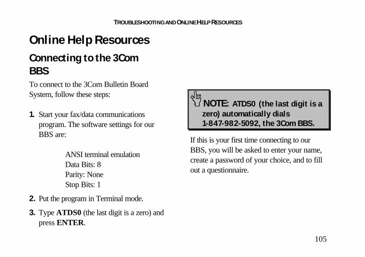
TROUBLESHOOTING AND ONLINE HELP RESOURCES
105
Online Help ResourcesConnecting to the 3ComBBSTo connect to the 3Com Bulletin BoardSystem, follow these steps:
1. Start your fax/data communicationsprogram. The software settings for ourBBS are:
ANSI terminal emulationData Bits: 8Parity: NoneStop Bits: 1
2. Put the program in Terminal mode.
3. Type ATDS0 (the last digit is a zero) andpress ENTER.
NOTE: ATDS0 (the last digit is a zero) automatically dials 1-847-982-5092, the 3Com BBS.
If this is your first time connecting to ourBBS, you will be asked to enter your name,create a password of your choice, and to fillout a questionnaire.

TROUBLESHOOTING AND ONLINE HELP RESOURCES
106
The introductory screen of the 3Com BBSwill look like the screen shot below. TheBBS gives you access to customer andtechnical support documents and the BBSlibrary. The library contains hundreds ofhelpful files and tips to help simplify usingyour modem.
When you are ready to leave the BBS, typeG (for “good-bye”) from the main menu.
3Com offers a number of other onlinetechnical support options. Choose any one ofthe following options for help with and/ormore information on your new modem.
Internet FTPProvides free library containing the same filesas the BBS site. FTP to ftp.usr.com.
Internet on DemandProvides automatic technical support througha library containing product information,quick reference cards, and installation help.To obtain an index of available documents,send a blank e-mail to [email protected] have a specific document e-mailed to you,send the document's number in the subject field.

TROUBLESHOOTING AND ONLINE HELP RESOURCES
107
World Wide WebA 3Com Web page containing the sameinformation as the Internet on Demand listing.Log on to:http://www.usr.com/home/online/
CompuServeAccess the same information as the InternetFTP site. The 3Com forum address is GOTHREECOM. Address private messages to76711,707.
America OnlineConnect to 3Com through America Online.Go to the Keyword field and type 3Com toconnect to various 3Com resources, such asfile libraries, message boards, onlinecustomer support, and productannouncements.
Customer Support viathe PhoneTechnical questions about 3Com modemscan also be answered by technical supportspecialists.
NOTE: Before calling, please havethe diagnostic program, ModemStation, installed on your system.The program is on the ConnectionsCD that came with the modem. Toinstall the program on your system,follow the instructions on thefollowing page.

TROUBLESHOOTING AND ONLINE HELP RESOURCES
108
1. Insert the Connections CD into yourCD-ROM drive.
2. Double-click the My Computer icon onyour desktop.
3. Double-click the CD-ROM icon.4. Double-click the usrtools folder.5. Double-click the umssetup icon.6. Follow the on-screen instructions.
This program may help the specialist solvethe problem quickly and shorten the cost ofthe call.
Regular Service(847) 982-51518:00 am - 6:00 pm CST
Priority, No-Hold Service3Com also staffs its own fee-based 900number for immediate assistance. These linesare staffed from 8 a.m. - 6 p.m. CSTMonday through Friday.No-Hold line 900-555-USR1
For a no-hold call, a $1.50 per minute chargewill appear on your local phone bill. Youmust be 18 or older or have parentalpermission. (Service available in the U.S.only.)
Are You Still HavingProblems?• Review this manual.• Call or visit your modem dealer. They
may be able to provide immediateassistance.

TROUBLESHOOTING AND ONLINE HELP RESOURCES
109
• If your dealer can't help you, contact3Com Customer Support. When youcall, specify your modem serial number(found on the modem and on the outsideof the box), the software being used, and,if possible, have the contents of yourATI7 screen available.
If You Need to Return theModem to Us for RepairContact 3Com Customer Support. If thesupport representative determines that youneed to return the modem for repair, you willreceive an SRO (Service Repair Order)number. You must have an SRO numberbefore returning the modem to us.
Ship the unit, postage paid, in a strong boxmade of corrugated cardboard with plenty of
packing material. DO NOT send the modemback in the original box.
Send ONLY the modem (NOT the powersupply, manuals, CD-ROM, etc.).
Include your SRO number, name, andaddress on the shipping label as well as insidethe package.
Send the package via a courier capable oftracking the progress of the shipment.
Ship to the following address:3Com
Attn: RMASRO#________________
6201 W. Oakton, East DockMorton Grove, IL 60053
GLOSSARY
110
Cross references are printed in boldface. Crossreferences to items also found in the “TechnicalQuick Reference” chapter are printed in italics.
analog loopbackA modem self-test in which data from thekeyboard or an internal test pattern is sent tothe modem's transmitter, turned into analogform, looped back to the receiver, andconverted back into digital form.
analog signalsA variety of signals and wavelengths that canbe transmitted over communications lines suchas the sound of a voice over the phone line.
answer modeThe mode used by your modem whenanswering an incoming call from an originatingmodem. The transmit/receive frequencies are
the reverse of the originating modem, which isin originate mode.
applicationA computer program designed to perform aspecific task or set of tasks. Examples includeword processing and spreadsheet applications.
ARQAutomatic Repeat reQuest. A function thatallows your modem to detect flawed data andrequest that it be retransmitted. See MNP andV.42.
ASCIIAmerican Standard Code for InformationInterchange. A code used to represent letters,numbers, and special characters such as $, !,and /.

GLOSSARY
111
asynchronous transmissionData transmission in which the length of timebetween transmitted characters may vary.Because characters may not be transmitted atset intervals, start/stop bits are used to markthe beginning and end of each character.
auto answerSets the modem to pick up the phone linewhen it detects a certain number of rings. SeeS-register S0 in the “Technical QuickReference.”
auto dialA process where your modem dials a call foryou. The dialing process is initiated by sendingan ATDT (dial tone) or ATDP (dial pulse)command followed by the telephone number.Auto dial is used to dial voice numbers. Seecommand Dn.
baud rateA term used to measure the speed of an analogtransmission from one point to another.Although not technically accurate, baud rate iscommonly used to mean bit rate.
binary digitA 0 or 1, reflecting the use of the binarynumbering system. Used because the computerrecognizes either of two states, OFF or ON.Shortened form of binary digit is bit.
bit rateAlso referred to as transmission rate. Thenumber of binary digits, or bits, transmittedper second (bps). Communications channelsusing analog modems are established at set bitrates, commonly 2400, 4800, 9600, 14,400,28,800 and higher.

GLOSSARY
112
bits per second (bps)The bits (binary digits) per second rate.Thousands of bits per second are expressed askilobits per second (kbps).
bufferA temporary memory area used as storageduring input and output operations. Anexample is the modem's command buffer.
byteA group of binary digits stored and operatedupon as a unit. Most often the term refers to 8-bit units or characters. One kilobyte (KB) isequal to 1,024 bytes or characters; 640 KB isequal to 655,360 bytes or characters.
carrierThe basic signal altered or modulated by themodem in order to carry information.
characterA representation, coded in binary digits, of aletter, number, or other symbol.
characters per second (CPS)A data transfer rate generally estimated fromthe bit rate and the character length. Forexample, at 2400 bps, 8-bit characters withstart/stop bits (for a total of ten bits percharacter) will be transmitted at a rate ofapproximately 240 characters per second(cps). Some protocols, such as error-controlprotocols, employ advanced techniques suchas longer transmission frames and datacompression to increase cps.

GLOSSARY
113
class 1 and 2.0International standards used by faxapplication programs and faxmodems forsending and receiving faxes.
cyclic redundancy checking (CRC)An error-detection technique consisting of atest performed on each block or frame of databy both sending and receiving modems. Thesending modem inserts the results of its tests ineach data block in the form of a CRC code.The receiving modem compares its results withthe received CRC code and responds witheither a positive or negative acknowledgment.
data communicationsThe transmission or sharing of data betweencomputers via an electronic medium.
data compression tableA table containing values assigned for eachcharacter during a call under MNP5 datacompression. Default values in the table arecontinually altered and built during each call:The longer the table, the more efficientthroughput gained.
data modeMode used by a modem when sending andreceiving data files.
DCEData Communications (or Circuit-Terminating) Equipment, such as dial-upmodems that establish and control the data linkvia the telephone network.

GLOSSARY
114
defaultAny setting assumed, at startup or reset, by thecomputer's software and attached devices. Thecomputer or software will use these settingsuntil changed by the user or other software.
detect phaseIn the ITU-T V.42 error-control protocol, thefirst stage in establishing if both modemsattempting to connect have V.42 capability.
dictionaryThe term used for compression codes built bythe V.42 bis data compression algorithm.
digital loopbackA test that checks the modem's RS-232interface and the cable that connects theterminal or computer and the modem. Themodem receives data (in the form of digitalsignals) from the computer or terminal, andimmediately returns the data to the screen forverification.
digital signalsDiscrete, uniform signals. In this manual, theterm refers to the binary digits 0 and 1.
DTEData Terminal (or Terminating) Equipment. Acomputer that generates or is the finaldestination of data.

GLOSSARY
115
duplexIndicates a communications channel capable ofcarrying signals in both directions. See halfduplex, full duplex.
Electronic Industries Association (EIA)Group which defines electronic standards inthe U.S.
error controlVarious techniques that check the reliability ofcharacters (parity) or blocks of data. V.42and MNP error-control protocols use errordetection (CRC) and retransmission of flawedframes (ARQ).
facsimileA method for transmitting the image on a pagefrom one point to another. Commonly referredto as fax.
fax modeThe mode used by a modem to send andreceive data in facsimile format. Seedefinitions for V.17, V.27ter, V.29.
flow controlA mechanism that compensates for differencesin the flow of data into and out of a modem orother device. See commands &Hn, &In, &Rn.
frameA data communications term for a block ofdata with header and trailer informationattached. The added information usuallyincludes a frame number, block size data,error-check codes, and Start/End indicators.

GLOSSARY
116
full duplexSignals can flow in both directions at the sametime over one line. In microcomputercommunications, may refer to the suppressionof the online local echo.
half duplexSignals can flow in both directions, but onlyone way at a time. In microcomputercommunications, may refer to activation of theonline local echo, which causes the modem tosend a copy of the transmitted data to thescreen of the sending computer.
HzHertz, a frequency measurement unit usedinternationally to indicate cycles per second.
ITU-TAn international organization that definesstandards for telegraphic and telephoneequipment. For example, the Bell 212Astandard for 1200-bps communication inNorth America is observed internationally asITU-T V.22. For 2400-bps communication,most U.S. manufacturers observe V.22 bis.
LAPMLink Access Procedure for Modems. Anerror-control protocol defined in ITU-TRecommendation V.42. Like the MNPprotocols, LAPM uses cyclic redundancychecking (CRC) and retransmission ofcorrupted data (ARQ) to ensure datareliability.

GLOSSARY
117
local echoA modem feature that enables the modem todisplay keyboard commands and transmitteddata on the screen. See command En.
MNPMicrocom Networking Protocol, an error-control protocol developed by Microcom,Inc., and now in the public domain. There areseveral different MNP protocols, but the mostcommonly used one ensures error-freetransmission through error detection (CRC)and retransmission of flawed frames.
modemA device that transmits/receives computer datathrough a communications channel such asradio or telephone lines. It also changes signalsreceived from the phone line back to digitalsignals before passing them to the receivingcomputer.
nonvolatile memory (NVRAM)User-programmable random access memorywhose data is retained when power is turnedoff. On the U.S. Robotics modem, it includesfour stored phone numbers and the modemsettings.
off/on hookModem operations that are the equivalent ofmanually lifting a phone receiver (taking it off-hook) and replacing it (going on-hook).

GLOSSARY
118
online fall back/fall forwardA feature that allows high-speed, error-controlmodems to monitor line quality and fall back tothe next lower speed in a defined range if linequality diminishes. As line conditions improve,the modems switch up to the next higherspeed.
originate modeThe mode used by your modem when initiatingan outgoing call to a destination modem. Thetransmit/receive frequencies are the reverse ofthe called modem, which is in answer mode.
parityA simple error-detection method that checksthe validity of a transmitted character.Character checking has been surpassed bymore reliable and efficient forms of errorchecking, including V.42 and MNP 2-4protocols. Either the same type of parity mustbe used by two communicating computers, orboth may omit parity.
protocolA system of rules and procedures governingcommunications between two or more devices.Protocols vary, but communicating devicesmust follow the same protocol in order toexchange data. The format of the data,readiness to receive or send, error detectionand error correction are some of theoperations that may be defined in protocols.
GLOSSARY
119
RAMRandom Access Memory. Memory that isavailable for use when the modem is turned on,but that clears of all information when thepower is turned off. The modem's RAM holdsthe current operational settings, a flow controlbuffer, and a command buffer.
remote digital loopbackA test that checks the phone link and a remotemodem's transmitter and receiver.
remote echoA copy of the data received by the remotesystem, returned to the sending system, anddisplayed on the screen. Remote echoing is afunction of the remote system.
ROMRead Only Memory. Permanent memory, notuser-programmable.
serial transmissionThe consecutive flow of data in a singlechannel. Compare to parallel transmissionswhere data flows simultaneously in multiplechannels.
start/stop bitsThe signaling bits attached to a characterbefore and after the character is transmittedduring asynchronous transmission.

GLOSSARY
120
terminalA device whose keyboard and display areused for sending and receiving data over acommunications link. Differs from amicrocomputer or a mainframe in that it haslittle or no internal processing capabilities.
terminal modeSoftware mode that allows directcommunication with the modem. Also knownas command mode.
throughputThe amount of actual user data transmitted persecond without the overhead of protocolinformation such as start/stop bits or frameheaders and trailers. Compare withcharacters per second.
V.8The ITU-T standard specification that coversthe initial handshaking process.
V.17 faxAn ITU-T standard for making facsimileconnections at 14,400 bps, 12,000 bps, 9,600bps, 7,200 bps.
V.21An ITU-T standard for modems operating inasynchronous mode at speeds up to 300 bps,full-duplex, on public switched telephonenetworks.
GLOSSARY
121
V.22An ITU-T standard for modemcommunications at 1200 bps, compatible withthe Bell 212A standard observed in the U.S.and Canada.
V.22 bisAn ITU-T standard for modemcommunications at 2400 bps. The standardincludes an automatic link negotiation fallbackto 1200 bps and compatibility with Bell212A/V.22 modems.
V.27 terAn ITU-T standard for facsimile operationsthat specifies modulation at 4800 bps, withfallback to 2400 bps.
V.29An ITU-T standard for facsimile operationsthat specifies modulation at 9600 bps, withfallback to 7200 bps.
V.32An ITU-T standard for modemcommunications at 9600 bps and 4800 bps.V.32 modems fall back to 4800 bps when linequality is impaired.
V.32 bisAn ITU-T standard that extends the V.32connection range: 4800, 7200, 9600, 12,000,and 14,400 bps. V.32 bis modems fall back tothe next lower speed when line quality isimpaired, fall back further as necessary, andalso fall forward (switch back up) when lineconditions improve (see online fall back/fallforward).

GLOSSARY
122
V.34An ITU-T standard that currently allows datarates as high as 28,800 bps.
V.34+An enhancement to V.34 that enables datatransfer rates as high as 33,600 bps.
V.42An ITU-T standard for modemcommunications that defines a two-stageprocess of detection and negotiation forLAPM error control.
V.42 bisAn extension of ITU-T V.42 that defines aspecific data compression scheme for useduring V.42 connections.
XmodemThe first of a family of error control softwareprotocols used to transfer files betweenmodems. These protocols are in the publicdomain and are available from many bulletinboard services.
XON/XOFFStandard ASCII control characters used totell an intelligent device to stop/resumetransmitting data.
YmodemAn error-checking protocol that can sendseveral files of data at a time in 1024-byte(1K) blocks. This protocol can use eitherchecksums or CRC for error checking.

GLOSSARY
123
Ymodem GSimilar to Ymodem, except it includes no errorchecking, which makes it faster.
ZmodemSimilar to Xmodem and Ymodem, except itincludes batch transfer, the ability to recoverfrom a partially complete transfer, an autostartfeature, and improved efficiency.

REGULATORY INFORMATION
124
Manufacturer’s Declarationof Conformity3Com Corporation7770 North Frontage RoadSkokie, Illinois 60077-2690U.S.A.
declares that the product U.S. Robotics® 56KFaxmodem conforms to the FCC’sspecifications:
Part 15; Subpart B Class BOperation is subject to the following twoconditions:(1) this device may not cause harmfulelectromagnetic interference, and(2) this device must accept any interference
received including interference that may causeundesired operations.
Part 68:This equipment complies with FCC Rules Part68. Located on the bottom of the modem isthe FCC Registration Number and RingerEquivalence Number (REN). You mustprovide this information to the telephonecompany if requested.
The REN is used to determine the number ofdevices you may legally connect to yourtelephone line. In most areas, the sum of theREN of all devices connected to one line mustnot exceed five (5.0). You should contactyour telephone company to determine themaximum REN for your calling area.

REGULATORY INFORMATION
125
This equipment uses the following USOCjacks: RJ11C.
This equipment may not be used on coinservice provided by the telephone company.Connection to party lines is subject to statetariffs.
An FCC compliant telephone cord andmodular plug are provided with this equipment,which is designed to connect to the telephonenetwork or premises wiring using a Part 68compliant compatible jack. See installationinstructions for details.
Caution to the UserThe user is cautioned that any changes ormodifications not expressly approved by theparty responsible for compliance could voidthe user’s authority to operate the equipment.
IC (Canada)This digital apparatus does not exceed theClass B limits for radio noise emissions fromdigital apparatus set out in the interference-causing equipment standard entitled DigitalApparatus, ICES-003 of Industry Canada.Cet appareil numérique respecte les limites debruits radioélectriques applicables auxappareils numériques de Classe B préscritesdans la norme sur le matériel brouilleur:Appareils Numériques, NMB-003 édictéepar l'Industrie Canada.
UL Listing/CUL ListingThis information technology equipment is UL-Listed and CUL-Listed for use with UL-Listedpersonal computers that have installationinstructions detailing user installation of cardcage accessories.
REGULATORY INFORMATION
126
Connecting to the Telephone CompanyIt is not necessary to notify the telephonecompany before installing the modem.However, the telephone company mayrequest the telephone number(s) to which theU.S. Robotics modem is connected and theregulatory information printed in this section.
Be sure that the telephone line you areconnecting the modem to is a standardanalog line and not a digital (PBX), party, orcoin telephone line.
If the modem is malfunctioning, it may affectthe telephone lines. In this case, disconnectthe modem until the source of the difficulty istraced.
Fax BrandingThe Telephone Consumer Protection Act of1991 makes it unlawful for any person to use acomputer or other electronic device, includingfax machines, to send any message unless suchmessage clearly contains in a margin at the topor bottom of each transmitted page or on thefirst page of the transmission, the date and timeit is sent, an identification of the business orother entity, or other individual sending themessage, and the telephone number of thesending machine or of such business, otherentity, or individual. (The telephone numberprovided may not be a 900 number or anyother number for which charges exceed localor long-distance transmission charges.)
In order to program this information into yourU.S. Robotics modem, refer to theRapidComm manual on the CD-ROM that

REGULATORY INFORMATION
127
shipped with your modem. If you’re using adifferent communications software program,refer to its manual.
Radio and Television InterferenceThis equipment generates and uses radiofrequency energy and if not installed and usedproperly, in strict accordance with themanufacturer’s instructions, may causeinterference to radio and television reception.The modem has been tested and found tocomply with the limits for a Class B computingdevice in accordance with the specifications inPart 15 of the FCC rules, which are designedto provide reasonable protection against suchinterference in a residential installation.
However, there is no guarantee thatinterference will not occur in a particularinstallation. If this device does cause
interference to radio or television reception,which you can determine by monitoringreception when the modem is installed andwhen it is removed from the computer, try tocorrect the problem with one or more of thefollowing measures:
• Re-orient the receiving antenna (fortelevisions with antenna reception only) orcable input device.
• Relocate the computer with respect to thereceiver.
• Relocate the computer and/or the receiverso that they are on separate branch circuits.
If necessary, consult your dealer or anexperienced radio/television technician foradditional suggestions. You may find thefollowing booklet, prepared by the FederalCommunications Commission, helpful:
REGULATORY INFORMATION
128
How to Identify and Resolve Radio-TV Interference ProblemsStock No. 004-000-0345-4U.S. Government Printing OfficeWashington, DC 20402
In accordance with Part 15 of the FCC rules,the user is cautioned that any changes ormodifications to the equipment described inthis manual that are not expressly approved byU.S. Robotics, Inc. could void the user’sauthority to operate the equipment.
For Canadian Modem UsersNOTICE: The Industry Canada (IC) labelidentifies certified equipment. This certificationmeans the equipment meets certaintelecommunications network protective,operational, and safety
requirements as prescribed in the appropriateTerminal Equipment Technical Requirementsdocument(s). The Department does notguarantee the equipment will operate to theuser’s satisfaction.
Before installing this equipment, users shouldensure that it is permissible to be connected tothe facilities of the local telecommunicationscompany. The equipment must also beinstalled using an acceptable method ofconnection. In some cases, the company’sinside wiring associated with a single-line,individual service may be extended by meansof a certified connector assembly (telephoneextension cord.) The customer should beaware that compliance with the aboveconditions may not prevent degradation ofservice in some situations. Currently,telecommunication companies do not allow
REGULATORY INFORMATION
129
users to connect their equipment to jacksexcept in precise situations that are spelled outin tariffing arrangements with those companies.
Repairs to certified equipment should becoordinated by a representative designated bythe supplier. Any repairs or alterations madeby the user to this equipment, or equipmentmalfunctions, may give the telecommunicationscompany cause to request the user todisconnect the equipment.
For your own protection, make sure that theelectrical ground connections of the powerutility, telephone lines, and internal metallicwater pipe system, if present, are connectedtogether. This precaution may be particularlyimportant in rural areas.CAUTION: Do NOT attempt to make suchconnections yourself. Instead, contact an
electric inspection authority or electrician, asappropriate.
NOTICE: The Ringer Equivalence Number(REN) assigned to each terminal deviceprovides an indication of the maximum numberof terminals allowed to be connected to atelephone interface. The termination on aninterface may consist of any combination ofdevices subject only to the requirement that thesum of the Ringer Equivalence Numbers of allthe devices does not exceed 5.
The Ringer Equivalence Number is located onthe bottom of the modem’s case (externalmodems) or on the modem’s circuit board(internal modems).
REGULATORY INFORMATION
130
WARRANTY AND REPAIR SERVICECENTER:Keating Technologies25 Royal Crest Court, Suite 200Markham, ONT L3R 9X4
AVIS: L'étiquette de Industrie Canada identifiele matériel homologué. Cette étiquette certifieque le matériel est conforme à certaines normesde protection, d'exploitation et de sécurité desréseaux de télécommunications. Le Ministéren’assure toutefois pas que le matérielfonctionnera à la satisfaction de l’utilisateur.
Avant d’installer ce matériel, l’utilisateur doits’assurer qu’il est permis de le raccorder auxinstallations de l’enterprise locale detélécommunication. Le matériel doit égalementêtre installé en suivant une méthode acceptéede raccordment. L’abonné ne doit pas oublierqu’il est possible que la conformité aux
conditions énoncées ci-dessus n’empêche pas ledégradation du service dans certaines situations.
Les réparations de matériel homologué doiventêtre effectuées par un centre d’entretiencanadien autorisé désigné par le fournissuer. Lacompagnie de télécommunications peutdemander à l’utilasateur de débrancher unappareil à la suite de réparations ou demodifications effectuées par l’utilasateur ou àcause de mauvais fonctionnement.
Pour sa propre protection, l’utilisateur doits’assurer que tous les fils de mise à la terre dela source d’énergie électrique, des lignestéléphoniques et des canalisations d’eaumétalliques, s’il y en a, sont raccordé ensemble.Cette précaution est particulièrement importantedans les régions rurales.

REGULATORY INFORMATION
131
Avertissment: L’utilisateur ne doit pas tenterde faire ces raccordements luimême; il doitavoir recours à un service d’inspection desinstallations électriques, ou á un électricien,selon le cas.
NOTICE: L’Indice d’Equivalence de laSonnerie (IES) de chaque appareil donne uneindication du nombre maximal de terminaux quipeut être branché à l’interface téléphonique.La termination d’une interface peut consisterde n’importe qu’elle combinaison d’appareilssur le réseau, seulement si la somme des IESde tous les appareils n’excède pas 5.
L'Indice d'Equivalence de la Sonnerie (IES)est situé au revers du modem (modemsexternes), ou sur le circuit imprimé (modemsinternes).
Centre de guarantie et de service après-vente:
Keating Technologies25 Royal Crest Court, Suite 200Markham, ONT L3R 9X4
Limited Warranty
U.S. Robotics Access Corp., a subsidiaryof 3Com Corporation, warrants to theoriginal end-user purchaser that thisproduct will be free from defects inmaterials and workmanship for a period offive years from the date of purchase. Duringthe limited warranty period, and upon proofof purchase, the product will be repaired orreplaced (with the same or a similar model,which may be a refurbished model) at U.S.Robotics’ option, without charge for eitherparts or labor. This limited warranty shallnot apply if the product is modified,

REGULATORY INFORMATION
132
tampered with, misused, or subjected toabnormal working conditions (including, butnot limited to, lightning and water damage).
THIS LIMITED WARRANTY DOESNOT GUARANTEE YOUUNINTERRUPTED SERVICE. REPAIROR REPLACEMENT AS PROVIDEDUNDER THIS LIMITED WARRANTYIS THE EXCLUSIVE REMEDY OF THEPURCHASER. THIS LIMITEDWARRANTY IS IN LIEU OF ALLOTHER WARRANTIES, EXPRESS ORIMPLIED, INCLUDING, BUT NOTLIMITED TO, ANY IMPLIEDWARRANTY OFMERCHANTABILITY OR FITNESSFOR A PARTICULAR USE ORPURPOSE. U.S. ROBOTICS SHALL INNO EVENT BE LIABLE FOR ANY
SPECIAL, INDIRECT, INCIDENTAL,PUNITIVE, OR CONSEQUENTIALDAMAGES OF ANY KIND ORCHARACTER, INCLUDING,WITHOUT LIMITATION, LOSS OFREVENUE OR PROFITS, FAILURE TOREALIZE SAVINGS OR OTHERBENEFITS, LOSS OF DATA OR USE,DAMAGE TO EQUIPMENT, ANDCLAIMS AGAINST THE PURCHASERBY ANY THIRD PERSON, EVEN IFU.S. ROBOTICS HAS BEEN ADVISEDOF THE POSSIBILITY OF SUCHDAMAGES.
This limited warranty gives you specificlegal rights. You may have others, whichvary from state to state. Some states do notallow limitations on duration of an impliedwarranty, or the exclusion or limitation of

REGULATORY INFORMATION
133
incidental or consequential damages, so theabove exclusion or limitation may not applyto you.
To obtain service under this limited warranty,contact the U.S. Robotics Technical SupportDepartment at 847-982-5151 or by mail at3Com, 7770 N. Frontage Road, Attn.:Technical Support Dept., Skokie, Illinois60077-2690. You will be given a ServiceRepair Order (“SRO”) number to help U.S.Robotics keep track of your limited warrantyrequest. Once you have received your SROnumber, take or send the product, postageprepaid and insured to the following address:
3ComAttn: RMA[your SRO#]6201 W. Oakton, East DockMorton Grove, IL 60053
Pack the modem in a strong corrugatedcardboard box with plenty of packing material.DO NOT send the modem back in its originalbox. DO NOT send anything but the modem(do not send back the power supply, CD-ROM, documentation, etc.). Send the modemvia a courier capable of tracking the progressof the shipment. IMPORTANT: If you sendyour unit, pack it securely, and be sure thatyour SRO number is visible on the outside ofthe package.