us eva 22 summary timeline - nasa · us eva 22 summary timeline 07/02/2013 1 eva pet hr : ... fish...
TRANSCRIPT

US EVA 22 SUMMARY TIMELINE
07/02/2013 1 EVA
PET HR : MIN
IV/SSRMS EV1 (Chris Cassidy)
EV2 (Luca Parmitano)
Verify Inhibits Prior to Egress
Verify SGTRC Inhibits in place Verify MISSE 8 Inhibits in place
SSRMS setup
Begin coordinated powerdowns for Z1 Y-Bypass Jumpers
Verify Z1 Y-Bypass Jumper Inhibits in place
GETAHEADS:
Tempstow PMA 2 Cover Bag (MLM Ethernet/ 1553 Cables) (00:20)
MLM Ethernet Cable Install (00:40)
PDGF FOD Removal (00:20) PDGF 1553 Cable Install (00:30) Relocate APFR/TS (00:30)
EGRESS/SETUP (00:25) Post Depress (00:05) Egress (00:10) Setup (00:10)
SGTRC R&R (01:10)
Setup SGTRC (00:20)
Remove Failed SGTRC (00:10) Install Spare SGTRC (00:10) Cleanup SGTRC (00:30)
STBD RADIATOR GRAPPLE BAR INSTALL (01:25)
MBS Mast CLPA Setup (00:25)
Radiator Grapple Bar Setup (00:20)
Release Stbd Grapple Bar from POA (00:15)
Remove Grapple Bar FSE B (00:05) Remove Grapple Bar FSE A (00:10) Install Stbd Grapple Bar on S1 Radiator (00:10)
MLM POWER CABLE INSTALL (00:30) PORT RADIATOR GRAPPLE BAR INSTALL (00:40)
Release Port Grapple Bar from POA (00:05) Stow CLPA (00:10) Stow PMA 2 Cover Bag (00:15) Install Port Grapple Bar on P1 Radiator (00:10)
Z1 Y-BYPASS JUMPER INSTALL (01:00)
Retrieve Z1 Y-Jumpers (00:25) Install Z1 Y-Jumper Part 1 (Nadir) (00:20) Setup Z1 Y-Jumper Part 2 (Zenith) (00:15)
PMA 2 COVER INSTALL (00:35)
Cover Install (00:25) Bag Cleanup (00:10)
CLEANUP/INGRESS (00:30) Cleanup (00:10) Ingress (00:15) Pre Repress (00:05)
EGRESS/SETUP (00:25) Post Depress (00:05) Egress (00:10) Setup (00:10)
MISSE 8 RETRIEVAL (01:10)
MISSE 8 & AMS Photos (00:25)
Retrieve MISSE 8 ORMatE (00:10) Retrieve MISSE 8 PEC (00:15)
Stow MISSE 8 (00:20)
STBD RADIATOR GRAPPLE BAR INSTALL (01:25)
SSRMS Setup (00:45)
Release Stbd Grapple Bar from POA (00:15)
Install Stbd Grapple Bar on S1 Radiator (00:25) MBS MAST CLPA REMOVAL (00:30)
SSRMS Maneuver to MBS (00:15) Remove MBS Mast CLPA (00:15)
PORT RADIATOR GRAPPLE BAR INSTALL (00:40)
Release Port Grapple Bar from POA (00:05) Install Port Grapple Bar on P1 Radiator (00:35)
SSRMS CLEANUP (00:55)
SSRMS Maneuver to Egress (00:15)
SSRMS Cleanup (00:40) PMA 2 COVER INSTALL (00:40)
Bag Setup (00:10) Cover Install (00:20) Bag Cleanup (00:10)
CLEANUP/INGRESS (00:30) Cleanup (00:10) Ingress (00:15) Pre Repress (00:05)
00:00
01:00
02:00
03:00
04:00
05:00
06:00
06:30
00:00
01:00
02:00
03:00
04:00
05:00
06:00
06:30
US EVA 22 TOOL CONFIG
2 EVA
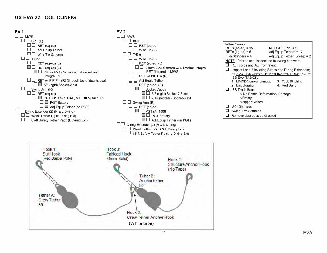
EV 1 MWS
BRT (L) RET (eq-eq) Adj Equip Tether Wire Tie (2, long) T-Bar RET (eq-eq) (L) RET (eq-eq) (L) 28mm EVA Camera w/ L-bracket and
integral RET RET w/ PIP Pin (R) (through top of dog-house) 5/8 (rigid) Socket-2 ext Swing Arm (R) RET (eq-eq) PGT [B1 Xft-lb, CAL, MTL 30.5] s/n 1002 PGT Battery Adj Equip Tether (on PGT)
D-ring Extender (2) (R & L D-ring) Waist Tether (1) (R D-ring Ext) 85-ft Safety Tether Pack (L D-ring Ext)
EV 2 MWS
BRT (L) RET (eq-eq) Wire Tie (2) T-Bar Wire Tie (2) RET (eq-eq) (L) 28mm EVA Camera w/ L-bracket; integral
RET (integral to MWS) RET w/ PIP Pin (R) Adj Equip Tether RET (eq-eq) (R) Socket Caddy 5/8 (rigid) Socket-7.8 ext 7/16 (wobble) Socket-6 ext Swing Arm (R) RET (eq-eq) PGT s/n 1008 PGT Battery Adj Equip Tether (on PGT)
D-ring Extender (2) (R & L D-ring) Waist Tether (2) (R & L D-ring Ext) 85-ft Safety Tether Pack (L D-ring Ext)
Tether Counts: RETs (eq-eq) = 15 RETs (PIP Pin) = 5 RETs (Lg-eq) = 6 Adj Equip Tethers = 12 Fish Stringers = 4 Adj Equip Tether (Lg-eq) = 2 NOTE: Prior to use, inspect the following hardware: RET cords and AET for fraying Inspect Load Alleviating Straps and D-ring Extenders; ref 2.230.100 CREW TETHER INSPECTIONS (SODF:
ISS EVA TASKS): 1. MMOD/general damage 3. Tack Stitching 2. Discoloration 4. Red Band ISS Trash Bag: No Bristle Deformation/ Damage Empty Zipper Closed BRT Stiffness Swing Arm Stiffness Remove dust caps as directed
(White tape)
US EVA 22 TOOL CONFIG
3 EVA
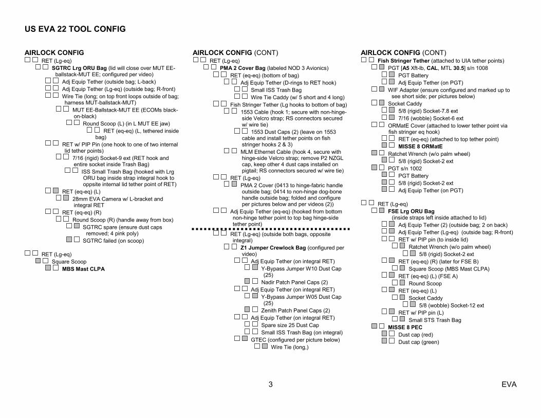
AIRLOCK CONFIG RET (Lg-eq)
SGTRC Lrg ORU Bag (lid will close over MUT EE-ballstack-MUT EE; configured per video)
Adj Equip Tether (outside bag; L-back) Adj Equip Tether (Lg-eq) (outside bag; R-front) Wire Tie (long; on top front loops outside of bag;
harness MUT-ballstack-MUT) MUT EE-Ballstack-MUT EE (ECOMs black-
on-black) Round Scoop (L) (in L MUT EE jaw) RET (eq-eq) (L, tethered inside
bag) RET w/ PIP Pin (one hook to one of two internal
lid tether points) 7/16 (rigid) Socket-9 ext (RET hook and
entire socket inside Trash Bag) ISS Small Trash Bag (hooked with Lrg
ORU bag inside strap integral hook to oppsite internal lid tether point of RET)
RET (eq-eq) (L) 28mm EVA Camera w/ L-bracket and
integral RET RET (eq-eq) (R) Round Scoop (R) (handle away from box) SGTRC spare (ensure dust caps
removed; 4 pink poly) SGTRC failed (on scoop)
RET (Lg-eq) Square Scoop MBS Mast CLPA
AIRLOCK CONFIG (CONT) RET (Lg-eq)
PMA 2 Cover Bag (labeled NOD 3 Avionics) RET (eq-eq) (bottom of bag) Adj Equip Tether (D-rings to RET hook) Small ISS Trash Bag Wire Tie Caddy (w/ 5 short and 4 long) Fish Stringer Tether (Lg hooks to bottom of bag) 1553 Cable (hook 1; secure with non-hinge-
side Velcro strap; RS connectors secured w/ wire tie)
1553 Dust Caps (2) (leave on 1553 cable and install tether points on fish stringer hooks 2 & 3)
MLM Ethernet Cable (hook 4, secure with hinge-side Velcro strap; remove P2 NZGL cap, keep other 4 dust caps installed on pigtail; RS connectors secured w/ wire tie)
RET (Lg-eq) PMA 2 Cover (0413 to hinge-fabric handle
outside bag; 0414 to non-hinge dog-bone handle outside bag; folded and configure per pictures below and per videos (2))
Adj Equip Tether (eq-eq) (hooked from bottom non-hinge tether point to top bag hinge-side tether point)
RET (Lg-eq) (outside both bags, opposite integral)
Z1 Jumper Crewlock Bag (configured per video)
Adj Equip Tether (on integral RET) Y-Bypass Jumper W10 Dust Cap
(25) Nadir Patch Panel Caps (2) Adj Equip Tether (on integral RET) Y-Bypass Jumper W05 Dust Cap
(25) Zenith Patch Panel Caps (2) Adj Equip Tether (on integral RET) Spare size 25 Dust Cap Small ISS Trash Bag (on integral) GTEC (configured per picture below) Wire Tie (long,)
AIRLOCK CONFIG (CONT) Fish Stringer Tether (attached to UIA tether points)
PGT [A5 Xft-lb, CAL, MTL 30.5] s/n 1008 PGT Battery Adj Equip Tether (on PGT) WIF Adapter (ensure configured and marked up to
see short side; per pictures below) Socket Caddy 5/8 (rigid) Socket-7.8 ext 7/16 (wobble) Socket-6 ext ORMatE Cover (attached to lower tether point via
fish stringer eq hook) RET (eq-eq) (attached to top tether point) MISSE 8 ORMatE Ratchet Wrench (w/o palm wheel) 5/8 (rigid) Socket-2 ext PGT s/n 1002 PGT Battery 5/8 (rigid) Socket-2 ext Adj Equip Tether (on PGT)
RET (Lg-eq) FSE Lrg ORU Bag (inside straps left inside attached to lid) Adj Equip Tether (2) (outside bag; 2 on back) Adj Equip Tether (Lg-eq) (outside bag; R-front) RET w/ PIP pin (to inside lid) Ratchet Wrench (w/o palm wheel) 5/8 (rigid) Socket-2 ext RET (eq-eq) (R) (later for FSE B) Square Scoop (MBS Mast CLPA) RET (eq-eq) (L) (FSE A) Round Scoop RET (eq-eq) (L) Socket Caddy 5/8 (wobble) Socket-12 ext RET w/ PIP pin (L) Small STS Trash Bag MISSE 8 PEC Dust cap (red) Dust cap (green)

US EVA 22 TOOL CONFIG
4 EVA
AIRLOCK CONFIG (CONT) Staging Bag
Fish Stringer Tether Long Duration Tie-Down Tethers (4) GTEC (configured per picture below) Wire Tie Caddy (w/ 5 short and 4 long) Velcro/Tape Caddy Probe Pin Straightener Assy EVA Wipe (dry) MWS Key Strap Assy Fish Stringer Tether Spare 85-ft Safety Tether Pack PGT, s/n 1007 PGT Battery Ratchet Wrench (w/o palm wheel) 7/16 (rigid) Socket-2 ext Spare WIF Adapter (ensure configured and
marked up to see short side; per pictures below)
Pry Bar Vise Grips Connector Cleaner Tool Kit (2 cartridges) P2 Cap (US MLM Ethernet Cable Cap)
IV Bag Towels (2) Contamination Detection Kit GP Caddy (2) Adjustable Thermal Mittens (2) Socket Caddy (hatch cont) w/RET (eq-eq) (Black) ½ (rigid) Socket-8 ext 7/16 (wobble) Socket-6 ext (spare) DCM Plug (SAFER Hardmount) (2) RET (eq-eq, Black) (2)
ISS CONFIG (EXTERNAL) External Airlock Airlock HR 0564 and 0567 FSE Lrg ORU Bag (inside straps left inside attached to lid) Adj Equip Tether (2) (outside bag; 2 on back) Adj Equip Tether (Lg-eq) (outside bag; R-front) RET w/ PIP pin (R) RET (eq-eq) (R) Grapple Bar FSE B RET (eq-eq) (L) Round Scoop Grapple Bar FSE A RET (eq-eq) (L) Socket Caddy 5/8 (wobble) Socket-12 ext RET (eq-eq) (L) Small STS Trash Bag
US EVA 22 TOOL CONFIG PICTURES
5 EVA
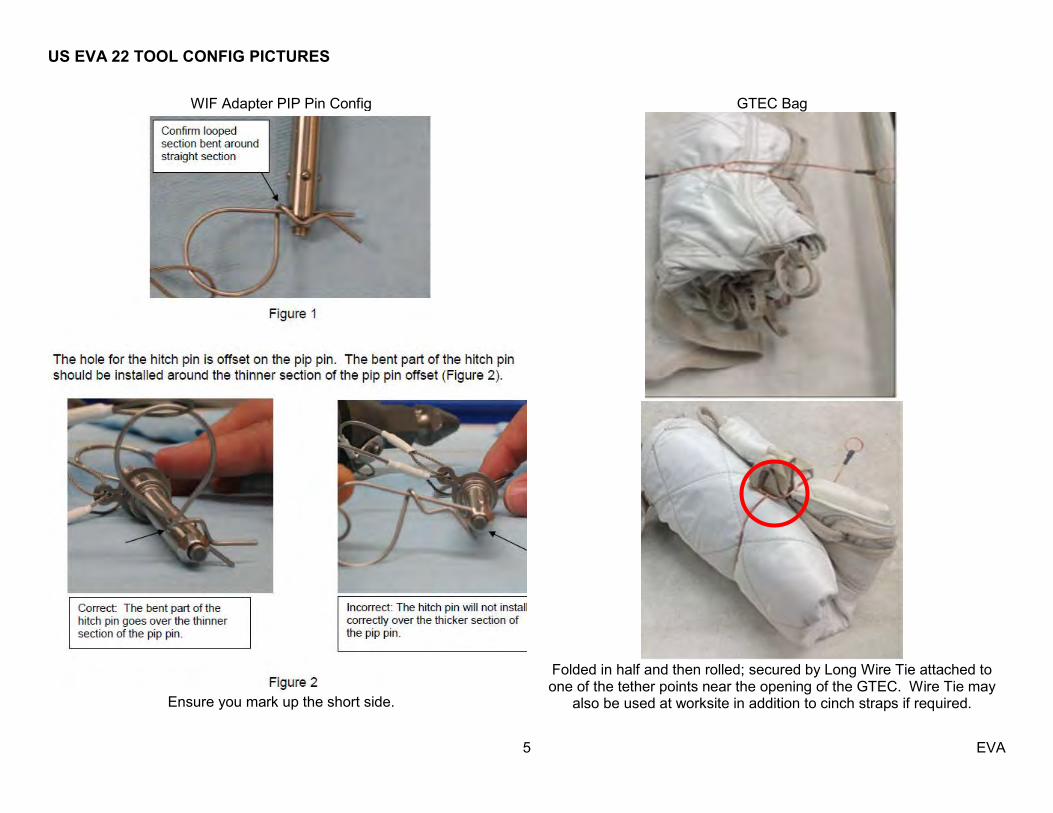
WIF Adapter PIP Pin Config
Ensure you mark up the short side.
GTEC Bag
Folded in half and then rolled; secured by Long Wire Tie attached to one of the tether points near the opening of the GTEC. Wire Tie may
also be used at worksite in addition to cinch straps if required.
US EVA 22 TOOL CONFIG PICTURES
6 EVA
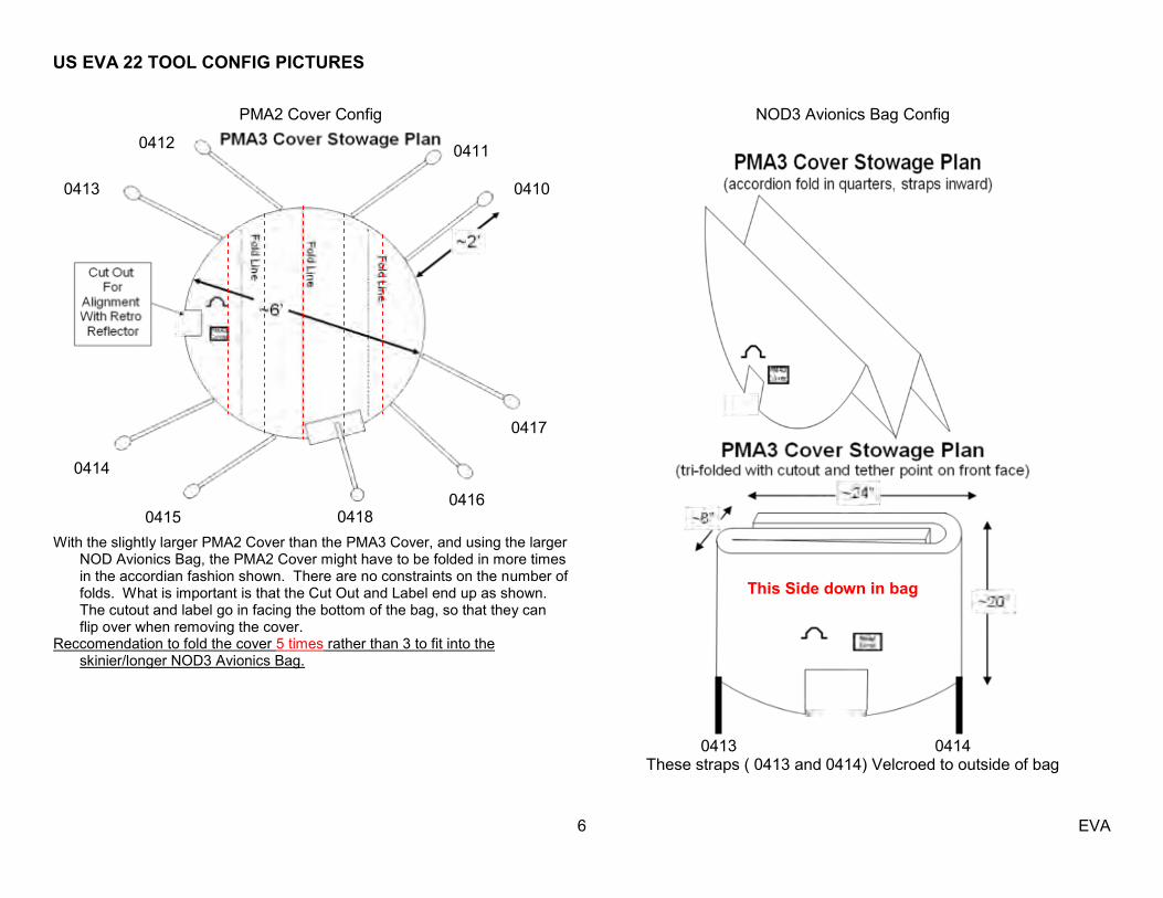
PMA2 Cover Config
With the slightly larger PMA2 Cover than the PMA3 Cover, and using the larger
NOD Avionics Bag, the PMA2 Cover might have to be folded in more times in the accordian fashion shown. There are no constraints on the number of folds. What is important is that the Cut Out and Label end up as shown. The cutout and label go in facing the bottom of the bag, so that they can flip over when removing the cover.
Reccomendation to fold the cover 5 times rather than 3 to fit into the skinier/longer NOD3 Avionics Bag.
NOD3 Avionics Bag Config
0413 0414 These straps ( 0413 and 0414) Velcroed to outside of bag
0417
0416 0418 0415
0414
0413
0412 0411
0410
This Side down in bag
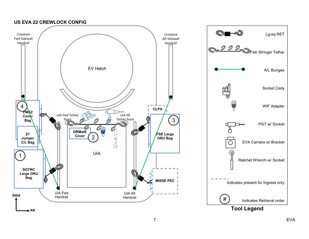
US EVA 22 CREWLOCK CONFIG
7 EVA
Crewlock
Fwd Sidewall Handrail
Tool Legend
Lg-eq RET
Fish Stringer Tether
A/L Bungee
Socket Cady
WIF Adapter
PGT w/ Socket
EVA Camera w/ Bracket
Ratchet Wrench w/ Socket
Indicates present for Ingress only
Indicates Retrieval order
#
UIA
UIA Fwd Tether Point
UIA Aft Tether Point
EV Hatch
Stbd
Aft
CLPA
SGTRC Large ORU
Bag
1
UIA Aft Handrail
Crewlock Aft Sidewall
Handrail
UIA Fwd Handrail
PMA2 Cover Bag
FSE Large ORU Bag
3
Z1 Jumper C/L Bag
4
ORMatE Cover 2
MISSE PEC

US EVA 22 BRIEFING CARD - CONDUCTED EVENING PRIOR TO EVA
8 EVA
4. People: IV – Karen
EV1 – Chris EV2 – Luca M1 – Karen Capcom / Ground IV – Shane Flight Dir – David Korth EVA Team – Ernie Bell, Alex Kanelakos, Grant Slusser, John Mularski 2. EVA Prep Get-up, Plan – clothing and EMU equipment bag – EV1 Prebreathe protocol review (Notes and cue card) – IV Equipment lock activities/responsibilities – IV
Extra people and ―help‖ management Suit donning plan – special requests – EV’s, IV’s SAFER, MWS, tools, C-Lk positions, bag stowage – EV2 Airlock depress review (Depress/Repress Cue Card) – IV 3. EV Crew Procedure Review – EV1 SAFETY, CONFIG, TASK Egress Plan, tethers, SAFER, MWS tabs Memorize / visualize first 4-5 minutes Order of tasks (summary timeline) Translation plan, fairleads and tether swaps Hazards Ingress Plan 4. Robotics – M1 SSRMS initial position, maneuvers, clearances Coordinate Frames SSRMS comm protocol review – expected calls, use first names GCA – when, where, handover language Cameras Contingencies Suit anomalies while ingressed
5. Communication – EV1 Overall setup: big picture, S/G2, Hardline, remind EV crew when
voice going to ground EV/IV comm protocol review – Use EV1(2) for DCM sw throws (all
time in A/L), use first names otherwise Handover to/from ground IV during Post-Depress/Pre-Repress 6. General Procedure Review – EV1 Get ahead tasks Constraints – ground and flight Notes, Cautions, Warnings review 7. Emergencies Review – EV1 Cuff checklist with no DCM warning: Loss of Cooling, Air Flow
Contamination, BITE light (wagon-wheel), DCS, Comm Failure No comm signs: ―OK,‖ ―PRI to Alt,‖ ―switch freq,‖ ―Terminate,‖
―Abort,‖ ―to AL‖ Lost tools, what if on SSRMS Incapacitated crew rescue Terminate: safe worksite, one or both get to airlock, go on SCUs Abort: Abandon worksites, both enter AL, no SCUs. Put sick guy
in, ingress, toss tethers or put on rail, close hatch IV rapid doffing steps: Equalize (EMER) and open IV hatch, O2
actuator OFF, purge valve up, pop glove. Remove helmet/LTA (going to be hot)
SAFER deploy, use auto-attitude hold button 8. Post EVA – IV Suit doffing responsibilities Post EVA plan (clean your own body fluids) 9. Morning of EVA – EV1 and EV2 ―Chair Fly‖ the whole timeline (5-10 mins)

US EVA 22 Notes/Cautions/Warning
9 EVA
CAUTION ISS Generic Constraints (cont) E. For structural reasons
1. The 2‖ socket may not disengage the anti-rotation device in a micro square fixture.
2. Avoid performing shaking motions (sinusoidal functions) for more than four cycles.
3. Avoid vigorous body motions, quick grabs, and kickoffs against tether restraints.
F. Other
1. ITT Cannon Connector: on demated connectors, do not rotate collar or manipulate cable or connector using collar or connector tool.
2. MLI handholds are not rated for crewmember translation loads.
NOTE 1. Bolt install: report torque and turns. 2. Bolt release: report torque and turns if
different from published range. 3. CETA Cart brake handle wire ties
must be replaced after crew loading, prior to next worksite 08 MT translation.
4. EVA connectors: after disconnection and prior to connection, verify pin and EMI band integrity; verify connector free of FOD.
5. Inspect QDs for damage prior to mating.
6. For HTV N/C/W, refer 3.14.102 HTV NOTES, CAUTIONS, & WARNINGS (SODF: EVA TASK: PROCEDURES: HTV).
7. 85-ft Safety Tether retraction force may affect body positioning.
8. Tool Box doors must be closed with one latch per door when EV crew not in immediate vicinity.
CAUTION ISS Generic Constraints A. Electrical cables
1. Avoid bend radii < 10 times cable diameter.
B. Fiber optic cables
1. Avoid bend radii < 10 times cable diameter.
2. Avoid pulling on cable during mate/demate.
C. Fluid line flex hoses and QDs
1. Avoid bend radii < 14" for hoses with a diameter ≥ 1".
2. Avoid bend radii less than 5" for hoses with diameter less than 1" on LAB, S0, S1, P1, and 10" for hoses with diameter less than 1" on all other elements.
3. Additional care should be taken to not exceed bend radii when applying loads at the flexible hose to rigid tube stub interfaces.
4. Ensure fluid QD booties are fully closed prior to leaving worksite; wire tie if required.
D. Avoid inadvertent contact
1. Grapple fixture shafts (drylube) 2. MBS/SSRMS/SPDM taped radiative
surfaces: VDU, ACU, JEU, LEU, MCU, CRPCMs, and Cameras
3. OTSD 4. PIP Pins 5. Passive UMAs 6. SPDM SJEU, EP, OTCM, LEU, and
LEE VDU radiator surfaces

US EVA 22 Notes/Cautions/Warning
10 EVA
CAUTION
ISS U.S. Pressurized Elements Constraints A. Avoid inadvertent contact
1. APAS hardware (PMA 2, PMA 3) 2. Open CBM petal covers, LAB and
Cupola window shutters 3. CETA Lights (Z-93 paint) (LAB, S1, S3,
P3, Node 1) 4. EVA Crane (PMA 1) 5. S0/Node 2 fluid tray hardlines at Node 2
end, which are limited to 25 lbs 6. MDM Radiator (PMA 1) 7. TCS reflectors (PMA 2, PMA 3) 8. UHF Antennas (LAB, P1)
B. RF radiation exposure 1. Stay 1.3 ft from Dragon UHF
transmitters when powered.
C. Other 1. CBM petal covers may not be used as
handholds unless both launch restraint pins are engaged.
2. EWIS Antennas: do not use as handholds (Node 1, LAB, P6, Z1)
CAUTION ISS Truss Constraints A. Avoid inadvertent contact
1. CETA lights (Z-93 paint) (LAB, S1, S3, P3, Node 1)
2. CMG cover/shells (Z1) 3. Deployed MISSEs 4. ETCS radiator flexhoses and panels
(S1, P1) 5. FPMU (P1) 6. GPS Antennas (S13 paint) (S0,
JLP) 7. Ku-Band Antenna (SGANT) dishes
(Z1) 8. OBSS composite sections, striker
bars, grapple fixture shafts, and cable harnesses
9. OTP on HAB Tray (S0) 10. PCU cathode and HCA ports (Z1) 11. EETCS/PV radiator flexhoses,
bellows, and panels (P6, P4, S4, S6)
12. RRM back radiator (Z-93 paint) (ELC-4)
13. S0 Aft face radiator 14. SASA high and low gain Antennas
and radiator surfaces (S1, P1, Z1) 15. Deployed TUS cable (Zenith and
Nadir CETA rails) 16. UHF Antennas (LAB, P1) 17. Heat pipe radiators (Z1)
B. For structural reasons 1. Avoid kicking S1/P1 radiator beam.
If this occurs, wait 2 to 5 minutes to allow structural response to dissipate
CAUTION ISS Truss Constraints (cont) C. Other
1. Lubricant from Ku-Band SGANT gimbals (Z1), CMGs (Z1), and RTAS ground strap fasteners (P6, P4, S4, S6) can contaminate EMU.
2. Prevent inadvertent contact of the Tether Shuttle with ETRS when the S3/P3 Tether Shuttle Stop is raised away from the rail.
3. EWIS Antennas: do not use as handholds (Node 1, LAB, P6, Z1)

US EVA 22 Notes/Cautions/Warning
11 EVA
CAUTION
ISS I.P. Elements Constraints A. Avoid inadvertent contact
1. COL ARISS and AIS Antennas (COL Nadir)
2. GPS Antennas (S13 paint) (S0, JLP)
3. ICS-EF Ka-Band Antenna dish 4. JEF ORUs and EFUs (paint and
lubricant) 5. JEM A/L target and pins 6. Trunnions and UCMs (paint and
lubricant) (JEF Payloads) 7. JEMRMS taped radiative surfaces
(JEU, EE, Cameras) 8. Open JPM window shutter 9. JTVE, WVE/EVE, JEF VE Cameras
10. MAXI front and top panel (paint) 11. MCE outboard and Nadir faces 12. RAIDS covers on end of HREP 13. SEDA-AP sensors (HIT, SDOM,
and AOM) 14. Small Fine Arm (SFA) (paint,
coating, and lubricant) B. For structural reasons
1. Avoid tool impact on ICS-EF sensor.
2. Avoid kicking MMOD shields between JLP and JPM.
WARNING ISS Generic Constraints A. Fluid line flex hoses and QDs
1. Bail may kick back suddenly when detent button is depressed if pressure has built up in spring cavity.
2. If QD is in FID when valve is opened (bail Fwd), QD will leak and fluid line may whip.
3. Do not rotate if in mated, valve open configuration.
B. Avoid inadvertent contact
1. Grapple fixture targets and target pins
C. Pinch 1. ITT Cannon Connector rotating
housing 2. NZGL connector linkage. Use caution
when mating/locking. 3. PDGF connector doors
D. Sharp edges 1. APFR active WIF probes 2. Mating surfaces of EVA connectors:
avoid side loads during connector mating.
3. Keep hands away from SSRMS LEE, POA, SPDM LEE opening, snares, and PDGF curvic coupling (teeth).
4. Back side of MMOD shield fasteners 5. MMOD strikes on ISS exterior 6. Inner edges of WIF sockets 7. SPDM OTCM gripper jaws
WARNING ISS Generic Constraints (cont)
8. Spring-loaded captive EVA fasteners (i.e., 6B boxes, BMRRM, RTAS, SARJ Covers); the end of the spring may protrude.
E. Thermal
1. EVA connectors with booties may become hot if left uncovered. Handling may need to be limited.
2. Do not touch EMU protective visor if temperature has been < -134 deg F for > 15 minutes.
3. No EMU boot contact with foot restraint when temperature < -120 deg F or > 200 deg F.
4. Turn off glove heaters when comfortable temperature reached to prevent bladder damage. Do not pull fingers out of gloves when heaters are on.
5. PDGF surfaces may not meet touch temperature requirements for unlimited contact when β ≤ -70 or β ≥ 70.
6. SSRMS/MBS/SPDM operating Cameras and lights may radiate large amounts of heat.
7. Uncovered trunnion pins may be hot.

US EVA 22 NOTES/CAUTIONS/WARNING
12 EVA
WARNING
ISS Truss Constraints A. Electrical shock
1. Stay ≥ 2 ft from ungrounded floating connectors if powered: S0 EVA power cables (inside S0 Bay 00 Face 4, Bay 01 Face 3); ESP-2 jumper (inside S0 Bay 03 Face 4)
2. Avoid all contact with the door which covers the blind mate connectors on passive FRAMs
B. Avoid inadvertent contact
1. SSU, ECU, beta gimbal platform, mast canister, SAW blanket boxes unless the beta gimbal is locked and the motor is turned off
2. Deployed MISSEs and ORMatE-III R/W (ELC-2)
3. Moving Radiator: stay 2 ft from S1/P1 radiator beam rotational envelope when beam is free to rotate.
4. HDEV windows 5. Moving SGANT Antenna: stay 3.3 ft
from Ku-Band Antenna when powered.
6. Moving MT: stay 5 ft from moving MT on Face 1.
7. Moving SARJ: stay inboard of SARJ when active.
8. SCAN Testbed payload hardware above the FRAM interface
9. STP-H3 Experiments: stay 1 ft from top of STP-H3 (ELC-3).
C. Pinch
1. Avoid contact with RRM above FRAM
WARNING ISS Truss Constraints (cont) C. Pinch (cont.)
2. Avoid pinch hazards on SCAN Testbed payload hardware above the FRAM interface.
D. RF radiation exposure
1. Stay 3.8 ft from S-Band (SASA) high gain Antenna when powered (S1, P1).
2. Stay 1.3 ft from S-Band (SASA) low gain Antenna when powered (S1, P1).
3. Stay out of KOZ for SCAN Testbed Ku- and S-Band Antennas when powered (ELC-3, P3, P1).
4. Stay 1.3 ft from UHF Antenna when powered (LAB, P1).
E. Sharp edges
1. AMS Star Trackers Baffles (two) 2. Nickel coated braided copper ground
straps may contain frayed wires (P6, P4, S4, S6)
3. LDRI Baffles (also an entrapment hazard) (OBSS)
4. Outboard MT rail attachment lug near P6 handrail 5333 and gap spanner
5. P2 connector on EWIS box TAA-06 (Zenith/Forward corner 1 of P5 - SARJ at 0 deg)
6. Avoid contact with RRM above FRAM.
7. SCAN payload (above FRAM) 8. Solar array blanket box (P6, S6) 9. Fastener threads on back of Z1 U-
jumper male FQD panel, if nutplate cap missing
WARNING ISS Truss Constraints (cont)
F. Thermal
1. ELC may exceed touch temperatures when β > 75 deg.
2. No EMU TMG contact with HRS radiator flex hoses at negative beta angles of 40 or higher magnitude. Temp can exceed 320 deg F, which may result in EMU suit bladder boiling. Avoid ESP-3 inboard face, S3 Nadir between ESP-3 and ELC-4, and ELC-4 outboard face.
3. No EMU TMG contact with RRM Coolant Valve Panel (top of RRM and ISS port when on ELC-4) and attached hardware. Temp can exceed 350 deg F, which may result in EMU layers melting and potential thermal shorts.
US EVA 22 NOTES/CAUTIONS/WARNING
13 EVA
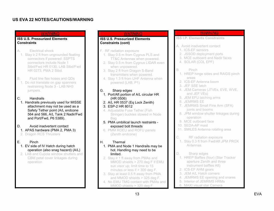
WARNING
ISS U.S. Pressurized Elements Constraints A. Electrical shock
1. Stay ≥ 2 ft from ungrounded floating connectors if powered: SSPTS connectors include Node 1 Stbd/Fwd HR 0130, LAB Stbd/Fwd HR 0273, PMA 2 Stbd.
B. Fluid line flex hoses and QDs
1. Do not translate on gap spanners restraining Node 3 - LAB NH3 jumpers.
C. Handrails
1. Handrails previously used for MISSE attachment may not be used as a Safety Tether point (A/L endcone 564 and 566, A/L Tank 2 Nadir/Fwd and Port/Fwd, P6 5389).
D. Avoid inadvertent contact
1. APAS hardware (PMA 2, PMA 3) 2. Dragon RCS Thrusters
E. Pinch 1. EV side of IV Hatch during hatch
operation (also snag hazard) (A/L) 2. LAB and Cupola window shutters and
CBM petal cover linkages during operation
WARNING ISS U.S. Pressurized Elements Constraints (cont) F. RF radiation exposure
1. Stay 0.5 m from Cygnus PLS and TT&C Antennas when powered.
2. Stay 0.5 m from Cygnus LIDAR even when unpowered.
3. Stay 2 ft from Dragon S-Band transmitters when powered.
4. Stay 1.3 ft from UHF Antenna when powered (LAB, P1)
G. Sharp edges 1. Port/Aft portion of A/L circular HR
(HR 0506) 2. A/L HR 0537 (Eq Lock Zenith) 3. ESP-2 HR 8012 4. Adjustable Fuse Tether (Fish
Stringer) buckles stowed in Node Bag
5. PMA umbilical launch restraints - exposed bolt threads
6. PMM ROEU and ROFU panels (Zenith endcone)
H. Thermal
1. PMA and Node 1 Handrails may be hot. Handling may need to be limited.
2. Stay ≥ 1 ft away from PMAs and MMOD shields > 270 deg F if EMU sun visor up; limit time to 15 minutes or less if > 300 deg F.
3. Stay at least 0.5 ft away from PMA and MMOD shields > 325 deg F.
4. No EMU TMG contact with PMAs and MMOD shields > 320 deg F.
WARNING ISS I.P. Elements Constraints A. Avoid inadvertent contact
1. ICS-EF sensors 2. JSSOD deployment ports 3. MCE outboard and Nadir faces 4. SOLAR (COL EPF)
B. Pinch 1. HREP hinge sides and RAIDS pinch
areas 2. ICS-EF Antenna boom 3. JEF SSE latch 4. JEM Cameras (JTVEs, EVE, WVE,
and JEF VEs) 5. JEM EFU latching arms 6. JEMRMS EE 7. JEMRMS Small Fine Arm (SFA)
joints and booms 8. JPM window shutter linkages during
operation 9. MCE outboard face
10. SEDA-AP mast 11. SMILES Antenna rotating area
C. RF radiation exposure 1. Stay 0.3 ft from Fwd/Aft JPM PROX
Antennas.
D. Sharp edges 1. HREP Baffles (four) (Star Tracker
aperture Zenith and three instrument baffles Aft)
2. ICS-EF AHM gears 3. JEM A/L Hatch corners 4. JEMRMS EE opening and snares 5. Interior of JEMRMS HRMs 6. MAXI visual star Camera
US EVA 22 NOTES/CAUTIONS/WARNING
14 EVA
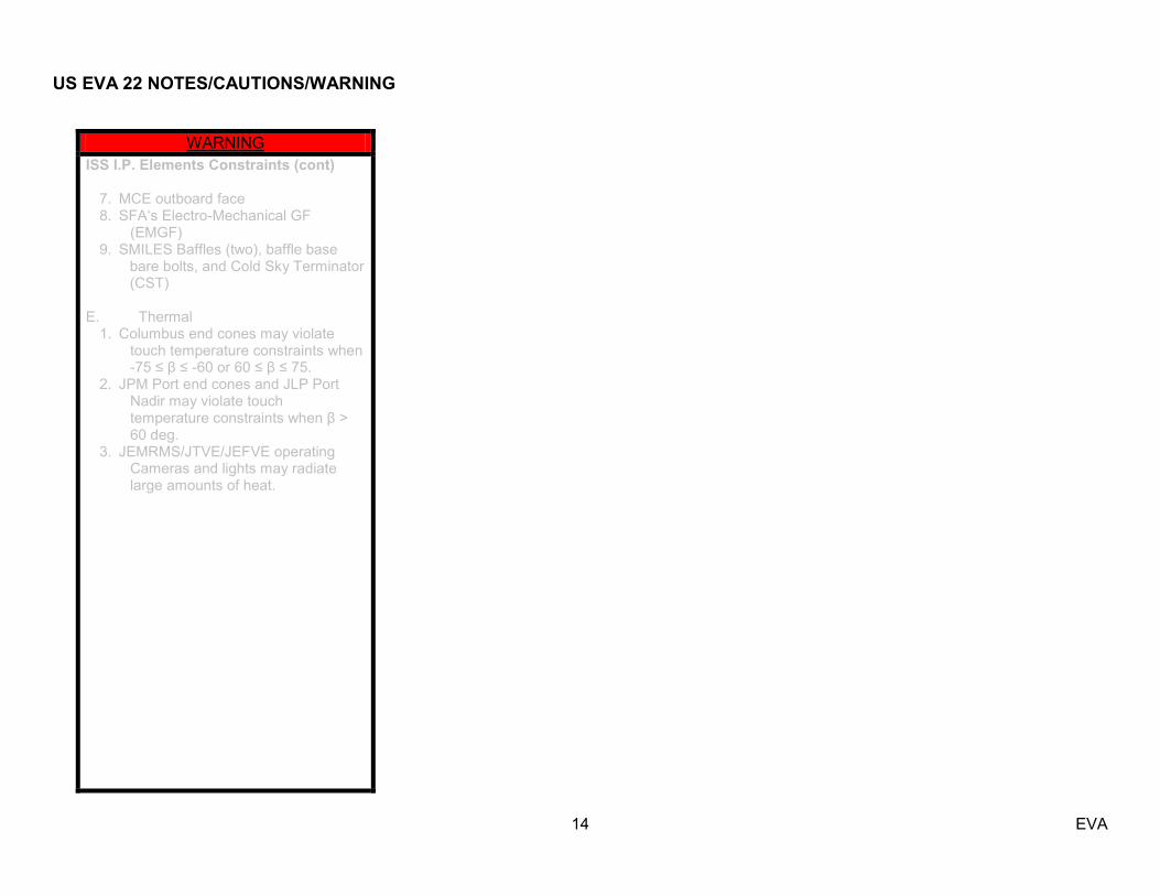
WARNING
ISS I.P. Elements Constraints (cont)
7. MCE outboard face 8. SFA‘s Electro-Mechanical GF
(EMGF) 9. SMILES Baffles (two), baffle base
bare bolts, and Cold Sky Terminator (CST)
E. Thermal
1. Columbus end cones may violate touch temperature constraints when -75 ≤ β ≤ -60 or 60 ≤ β ≤ 75.
2. JPM Port end cones and JLP Port Nadir may violate touch temperature constraints when β > 60 deg.
3. JEMRMS/JTVE/JEFVE operating Cameras and lights may radiate large amounts of heat.

US EVA 22 INHIBIT PAD
15 EVA
ALL EVAs (PRIOR TO EGRESS) ISS Hardware
1. COL ANTENNAS □ IV Crew
1. HAM Radio – Deactivate
2. CUCU □ IV Crew: LAB1O4
2. cb POWER A, B (two) – OPEN 3. cb LINK 1,2 (two) – OPEN
3. Ground Radar □ MCC-H: TOPO
1. Ground radar restrictions in place for EVA
4. ICS-EF Antenna □ SSIPC
1. ICS MOD – OFF 2. ICS UPC – OFF 3. ICS HPA – OFF 4. HPA ON and UPC ON commands are cleared (not
present) in the ICS stored command queue
5. MISSE 8 □ POIC: POD
1. ELC-2 ExPA-2 Discrete Channel 6 – Disabled
6. RUSSIAN PAYLOADS □ MCC-M: RIO
1. Control (КОНТРОЛ)– Deactivate 2. Indicator ISS
a. Unit of Input Converters (БВП)-Inhibit b. Control Unit (БУ)- Inhibit
7. PCU □ MCC-H: SPARTAN/SPOC
NOTE PCUs may require up to a 1-hour warmup period before they are operational.
1. PCUs (two) operational in discharge mode and one of
the following: a. CCS PCU EVA hazard control FDIR enabled, if
required or b. Only allowed arrays unshunted and oriented <105º
from velocity vector 2. If one or both PCUs failed
a. Only allowed arrays unshunted and oriented <105º from velocity vector
8. SM Antennas
□ IV Crew 1. ARISS (Ham Radio) – Deactivate □ MCC-M: RIO 1. GTS – Deactivate 2. Napor (РСПИ) – Deactivate 3. Laser Comm System (БТЛС-Н) – Deactivate
9. EKTS Communication System
□ MCC-M: RIO 1. EKTS Commincation System – Deactivate

US EVA 22 INHIBIT PAD
16 EVA
LOCATION-DEPENDENT (PRIOR TO EGRESS) RSOS
10. FGB ANTENNAS (1553 Cable, FBG PDGF FOD Removal, MLM Ethernet Cable)
□ MCC-M: RIO EVA on RSOS
1. TORU (TOPY) – Deactivated 2. TV System (TBC) – Deactivated 3. Radiotelemetry (БP-9ЦУ-8) – Deactivated 4. TV System (КЛ-108А) – Deactivated 5. CNPMS (CИТНП) – Deactivated 6. KOMPARUS (КИС) – Deactivated
11. RSOS and RSOS Visiting Vehicle Antennas (MLM Power Cable, 1553 Cable, FGB PDGF FOD Removal, MLM Ethernet Cable)
□ MCC-M: RIO EVA on PMA 1 or RSOS
1. KURS P (КУРС P) – Deactivated 2. KURS A (КУРС A) – Deactivated
12. SM ANTENNAS (1553 Cable, FBG PDGF FOD Removal, MLM Ethernet Cable)
□ MCC-M: RIO EVA on RSOS
1. LIRA (ОHА) – Deactivated
13. FGB PDGF Power (FBG PDGF FOD Removal) □ MCC-M: RIO
1. RACU-5 – OFF 2. RACU-6 – OFF
SYSTEM POWER Panel (ППC) FGB 313 3. БКC Cable 77КM-7228-110-01 – Demated 4. БКC Cable 77КM-7228-110 – Demated
LOCATION-DEPENDENT (PRIOR TO EGRESS) Visiting Vehicles
14. ATV Antennas (1553 Cable, FGB PDGF FOD Removal, MLM Ethernet Cable)
□ ATV-CC: RIO EVA on RSOS
1. PROXimity Link – Deactivated 2. KURS P: KMTA 1&2 – Deactivated
15. ATV Other Equipment (Lasers) (1553 Cable, FGB PDGF FOD Removal, MLM Ethernet Cable)
□ ATV-CC: RIO EVA on RSOS
1. Telegoniometer – Deactivated 2. Videometer – Deactivated
16. ATV Thrusters (MLM Power Cable, 1553 Cable,
FGB PDGF FOD Removal, MLM Ethernet Cable) □ ATV-CC: RIO
EVA on RSOS 1. ATV Attitude Control Thruster Valves (56) – Closed
17. SOYUZ THRUSTERS (1553 Cable, FBG PDGF FOD Removal, MLM Ethernet Cable)
□ MCC-M: RIO EVA on PMA 1 or RSOS
1. 35S Thruster on MRM 1 – Inhibited

US EVA 22 INHIBIT PAD
17 EVA
LOCATION-DEPENDENT (PRIOR TO EGRESS) USOS
18. Mobile Transporter (RGB Install, CLPA Removal)
□ MCC-H: ROBO/MSS SYSTEMS EV crew < 1.5 meters from MT
1. MT latched
19. MBS Mast CLPA (Mast CLPA Removal) □ MCC-H: ROBO/MSS SYSTEMS
1. CRPCM 3P RPC 5 (VDU-2 Primary Power) open 2. CRPCM 3R RPC 5 (VDU-2 Redundant Power) open
20. FPMU (Port RGB Install)
□ MCC-H: SPARTAN/SPOC EV crew on Port truss (P1-P6) or working within 5 feet of Floating Potential Measurement Unit
1. RPCM P11A_B RPC 13 Open/Close Cmd Inhibit 21. MLM Power Cable (MLM Power Cable Routing)
□ MCC-H: SPARTAN/SPOC 1. MBSU 1 RBI 5 Open/Close Cmd Inhibit 2. MBSU 3 RBI 5 Open/Close Cmd Inhibit
22. SSPTS (MLM Cable Routing and PMA 2 Cover) □ MCC-H: SPARTAN/SPOC
EV crew working within 2 feet of SSPTS cable connections 1. RPCM LA2A3B D RPC 1 – Open, Close Cmd Inhibit 2. RPCM Z14B A RPC 2 – Open, Close Cmd Inhibit 3. RPCM Z13B A RPC 2 – Open, Close Cmd Inhibit
23. Port TRRJ (RGB Install, APFR/TS Relocate) □ MCC-H: SPARTAN/SPOC
EV crew working within 2 feet of P1 TRRJ rotation envelope 1. DLA 1(2) – LOCKED at 0 deg 2. DLA 2(1) – ENGAGED 3. All motor setpoints set to zero 4. All motors deselected
24. Stbd TRRJ (RGB Install)
□ MCC-H: SPARTAN/SPOC EV crew working within 2 feet of S1 TRRJ rotation envelope
1. DLA 1(2) – LOCKED at 0 deg 2. DLA 2(1) – ENGAGED 3. All motor setpoints set to zero 4. All motors deselected
25. Port SARJ (MISSE 8, SSRMS Setup/Cleanup)
□ MCC-H: SPARTAN/SPOC EV crew working within 2 feet, outboard of SARJ, or required per loads FR (includes outboard faces of outboard ELCs/ESPs) 1. DLA 1(2) – LOCKED at 75 deg 2. DLA 2(1) – ENGAGED 3. All motor setpoints set to zero 4. All motors deselected
26. Stbd SARJ (MISSE 8, SSRMS Setup/Cleanup)
□ MCC-H: SPARTAN/SPOC EV crew working within 2 feet, outboard of SARJ, or required per loads FR (includes outboard faces of outboard ELCs/ESPs); NOT OK range: 55-95 deg and 235-275 deg 1. DLA 1(2) – LOCKED at 294 deg 2. DLA 2(1) – ENGAGED 3. All motor setpoints set to zero 4. All motors deselected

US EVA 22 INHIBIT PAD
18 EVA
LOCATION-DEPENDENT (PRIOR TO EGRESS) USOS
27. SGTRC #2 (SGTRC R&R)
□ MCC-H: CATO/STARCOM 1. RPCM Z14B_B RPC 3 (Ops Power) Open/Close
Cmd Inhibit
28. SCAN Testbed (RGB Install) □ POIC: POD (SCAN Testbed)
1. SSRMS or EV crew working within 5 meters of SCAN Ka-band antenna or if EV crew in KOZ (B19-31)
a. ELC-3 ECM ExPA-1 120V MAIN SWITCH – OFF
b. HARRIS SDR – OFF c. TWTA – OFF
2. SSRMS/SPDM/MBS within 1.3 meters of SCAN S-band antennas or if EV crew working within 0.7 meters of SCAN S-band antennas (refer to Flight Rule B19-31)
a. ELC-3 ECM ExPA-1 120V MAIN SWITCH – OFF
b. GC SDR – OFF (S-BAND POWER – OFF) c. JPL SDR – OFF (S-BAND POWER – OFF)
29. MISSE 8 (MISSE 8, RGB Install)
□ POIC: POD EV crew Zenith of the plane of MISSE 8 (includes ELC-2,
ELC-3, and SSRMS) (B19-30) 1. MISSE-8 PASCAL solar cells – Zero voltage bias 2. ELC-2 ExPA-2 Discrete Channel 1 – Disabled 3. ELC-2 ExPA-2 28V Operational Power – Disabled
Open FRAM Site 7 4. ELC-2: FRAM site 7 – ELC2, Power Module 1 & 2,
Channel 11 - Open CHIT 11457
5. ELC-2, Power Module 1 & 2, Channel 12 - Open
LOCATION-DEPENDENT (TIME DEPENDENT) USOS
30. SGTRC #2 (SGTRC R&R) – Egress □ MCC-H: CATO/STARCOM
1. RPCM Z13B_B RPC 3 (Heater Power) - Open, Close, Cmd Inhibit
31. MISSE 8 (MISSE 8) – Egress □ POIC: POD
EV crew performing MISSE 8 retrieval (B19-30) 1. ELC-2 ECM EXPA-2 120V OPEN 2. ELC-2 ECM EXPA-2 28V OPEN 3. ELC-2 EXPA-2 OP PWR OPEN 4. ELC-2 Power Module 1, Channel 8 OPEN
32. ESP2 Open FRAM Locations (SSRMS Setup, SSRMS Cleanup) – End of MISSE 8 Retrieval
□ MCC-H: SPARTAN/SPOC Site 1
1. RPC N1RS2-B, RPC 6 - Open, Close, Cmd Inhibit 2. S04B-F RPC 10 - Open, Close, Cmd Inhibit
Site 4 3. RPC N1RS2-B, RPC 10 - Open, Close, Cmd Inhibit 4. S04B-F RPC 12 - Open, Close, Cmd Inhibit
33. Z1 Y-Bypass Jumper (Z1 Jumper Install) –End of Install of Port RGB
□ MCC-H: SPARTAN/SPOC 1. IVA isolation jumpers installed 2. DDCU S04B converter off
34. NODE 3 J1 FGB & J2 FGB 1553 (Required for 1553 Cable) – Prior to Node 3 Connections
□ MCC-H: ROBO 1. If any RWS active, cmd ‗Active Assert Backup‘

US EVA 22 EGRESS/SETUP (00:25)
19 EVA
IV/SSRMS EV1 EV2 1. PET Start Time __ : __
(Pwr to Batt)
POST-DEPRESS (00:05) 1. All gates closed & hooks locked
Red hook on L D-ring Ext White hook on Anchor Reel Green hook on crew tether Reel Blank hook on MWS EV2 Safety Tether to R D-Ring Ext
POST-DEPRESS (00:05) 1. All gates closed & hooks locked
Red hook on L D-ring Ext White hook on Anchor Reel Green hook on crew tether Reel Blank hook to EV1 R D-ring Ext R Waist Tether to A/L D-ring Ext L Waist Tether to MWS
WARNING Sharp edge hazard: port/aft portion of A/L circular HR (0506) and Face 1 CETA rail
EGRESS (00:10) 2. Open A/L thermal cover
EGRESS (00:10)
2. Spare SGTRC bag Thermal Clock: __:__
3. MCC-H: Perform WETA Scan 4. Failed SGTRC Thermal Clock: __:__ 5. MISSE 8 PEC Thermal Clock: __:__ (2 hr)
3. Egress A/L, with SGTRC Bag, stow on BRT 4. Attach EV1 Safety Tether (blank hook) to aft A/L
tether point Gate closed, hook locked, reels unlocked 5. Relocate EV2 Safety Tether (blank hook) from R
Waist Tether to fwd A/L tether point Gate closed, hook locked reels unlocked 6. Give EV2 GO to release Waist Tether 7. Give EV2 GO to Egress
2. Release R Waist Tether from internal A/L D-ring Ext 3. On EV1 GO: Reposition UIA Fish Stringer hooks Egress A/L w/ ORMatE Cover and RET Stow on swing arm using RET on ORMatE Cover
L R L R A/L D-ring
Ext
EV1 85
85
85
85
EV2

US EVA 22 EGRESS/SETUP (00:25)
20 EVA
IV/SSRMS EV1 EV2 8. Perform buddy checks SAFER handles down Tethers and Tools WVS Green LED
4. Perform buddy checks SAFER handles down Tethers and Tools WVS Green LED 5. Close A/L thermal cover
6. Verify SGTRC Inhibits in place 7. Verify MISSE 8 Inhibits in place
SETUP (00:10) 9. Translate to Z1 zenith worksite via: aft on A/L zenith on NOD1 endcone, tool box, and Z1
WARNING Sharp edge hazard: stbd and port Z1 tool boxes
CAUTION Avoid contact with heat pipe radiators, SASA high
and low gain antennas and radiative surfaces, and SGTRC-2 Z93 paint
Do not use SGTRC connector bracket for restraint or stability loads
SETUP (00:10) 6. Perform translation adaptation 7. Translate to S1 HR 3200 (face 1) via: CETA Spur do not fairlead at base of CETA spur (let tether
tend stbd from A/L) 8. Attach Safety Tether green hook to S1 HR 3200
(mm 5850)
WARNING Do not touch hinged side while closing MISSE PEC
CAUTION Avoid contact with deployed MISSE, and silver
avionics boxes on ExPA. Keep tether fairlead free of MISSE.
NOTE Avoid sideloads when installing cover on ORMatE
Cover Labeled RAM side fwd MISSE PIP pins do not come all the way out of
sockets ‗

US EVA 22 SGTRC R&R / MISSE 8 RETRIEVAL (01:10)
21 EVA
IV/SSRMS EV1 EV2
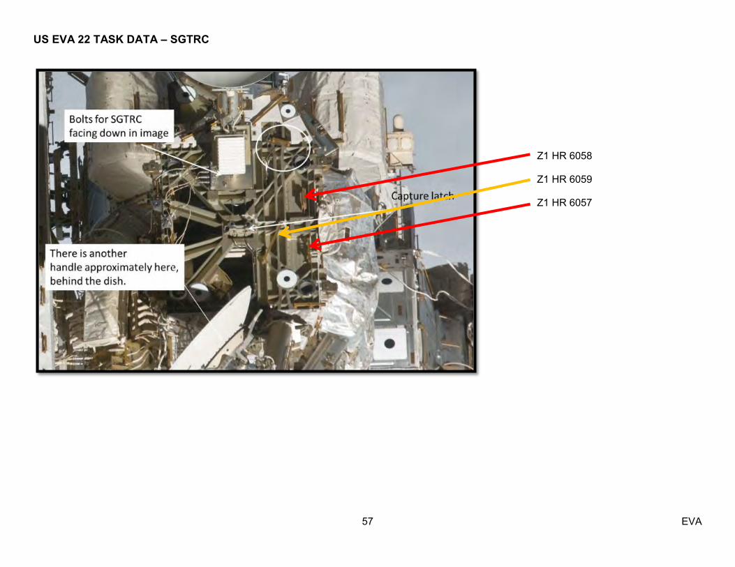
SETUP SGTRC (00:20) 1. Stow SGTRC Bag hinge aft on Z1 HR 6057 (Lg-eq
AET) and HR 6058 (eq-eq AET) 2. Retrieve Round Scoop from MUT, install on failed
SGTRC (handle orthogonal to box-pointing nadir) 3. Install MUT-Ballstack-MUT on Z1 HR 6059 (bias
stbd, close to SGANT boom), 4. Lock MUT EE jaws 5. Install 7/16 (rigid) Socket-9 ext on PGT Pull test
MISSE 8 PHOTOS (00:25) 1. Translate to ELC2 MISSE ExPA via fwd/zenith route Fairlead inboard SARJ HRs Fairlead outboard on ELC2 2. Photograph deployed MISSE 8, attempt to be
orthogonal and BRT as reqd; multiple photos are acceptable to get entire coverage
Fairlead underneath zenith FRAM HR Aft ORMatE (DCSU FRAM aft-zenith HR) Nadir PEC (DCSU FRAM aft-zenith HR) Zenith PEC (zenith MISSE FRAM HR) Fwd ORMatE (ELC2 HR 8603) Best effort pics of AMS, focusing on aft radiator
and zenith surface RETRIEVE MISSE 8 ORMatE (00:10) 3. Install ORMatE Cover on ORMatE payload align bottom tether points prevent sideloadings ORMatE 4. Engage Velcro strap 5. Move RET to ORMatE and Cover tether points near
probe 6. Release ORMatE (release 2 PIP pins), stow on
swing arm Reinstall socket PIP pins (2) RETRIEVE MISSE 8 PEC (00:15) 7. Translate to PEC 8. Close MISSE 8 PEC
disengage all 4 PIP pins rotate PEC lid 360-deg re-engage all 4 PIP pins
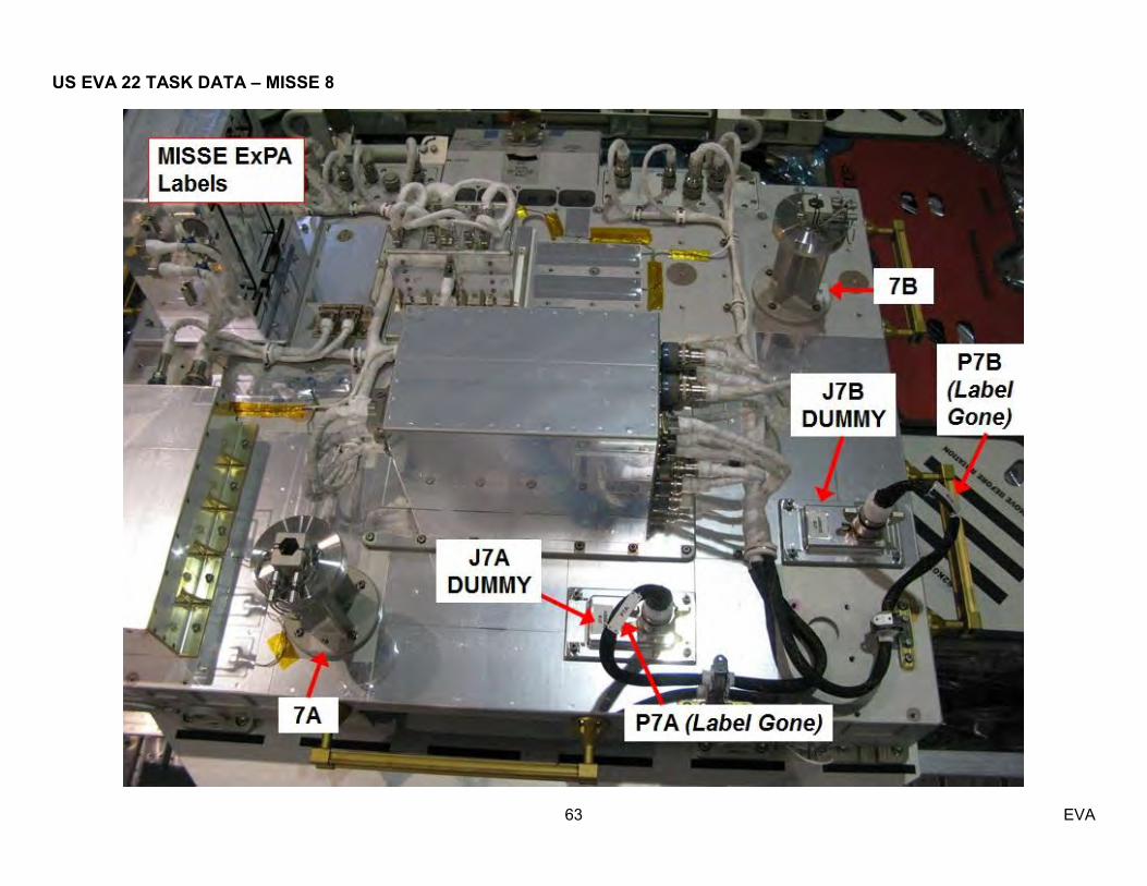
9. Demate MISSE 8 connector 7A: 7A cap (red) | dummy connector J7A J7A connector | PEC (lower connector) no FOD, pins J7A connector | dummy panel J7A
1. Spare SGTRC Thermal Clock: __:__
2. Record SGTRC bolt data:
Bolt Turns Torque (ft-lb) Center (2.5) Fwd (2.5) Aft (2.5)
6. Retrieve spare SGTRC from SGTRC Bag, install in MUT EE
paddles out REMOVE FAILED SGTRC (00:10) 7. BRT to SGANT-Boom #2 HR 0001 8. Configure PGT:
[B1 (12.0), CCW2, 30.5] 9-Ext 7/16 9. Release 2 outer fasteners ~ 10-13 turns Fwd Aft 10. Release center fastener ~28-31 turns (no soft dock
present - [B1 (12.0), CCW2, 30.5] 9-Ext 7/16) 11. Remove failed SGTRC, tend to SGTRC Bag INSTALL SPARE SGTRC (00:10) 12. Inspect blind mate connectors on boom receptacle
and spare SGTRC 13. As required, reposition spare SGTRC within reach 14. Configure PGT:
[A1 (2.5), CW2, 30.5] 9-Ext 7/16 15. Retrieve spare SGTRC from MUT-Ballstack-MUT 16. Install SGTRC (no soft dock present) 17. Drive center fastener ~28-31 turns to trq 18. Drive 2 outer fasteners ~ 10-13 turns to trq Fwd Aft
Zenith
Ram
ORMatE-III R/W
PEC 8
ExPA
Space Cube
HyperX
MCPE
JMU
GDPB

US EVA 22 SGTRC R&R / MISSE 8 RETRIEVAL (01:10)
22 EVA
IV/SSRMS EV1 EV2 3. Give CATO GO to restore power to
SGTRC
4. Give POIC GO to restore heater power
to ELC2 5. Verify ESP2 Inhibits in place
CLEANUP SGTRC (00:30) 19. Retrieve Round Scoop from SGTRC, install on MUT
EE, lock jaws 20. Stow 7/16 (rigid) Socket-9 ext on PIP pin RET, and
install 5/8 (rigid) Socket-2ext on PGT 21. Stow failed SGTRC in Bag 22. Retrieve MUT-Ballstack-MUT 23. Stow MUT-Ballstack-MUT on outside SGTRC Bag
with Wire Tie 24. Retrieve EVA Camera and RET 25. Perform SGTRC Bag Inventory SGTRC Lrg ORU Bag Adj Equip Tether (outside bag; L-back) Adj Equip Tether (Lg-eq) (outside bag; R-front) Wire Tie (long; on top front loops outside of bag) MUT EE-Ballstack-MUT EE (ECOMs black-on-black) Round Scoop (in MUT EE jaw) RET (eq-eq) (tethered inside bag) RET w/ PIP Pin (internal lid tether points) 7/16 (rigid) Socket-9 ext ISS Small Trash Bag (internal lid tether point) RET (eq-eq) Round Scoop SGTRC failed (on scoop) 26. Close SGTRC Bag, stow on BRT 27. Translate to Airlock 28. Open Thermal Cover 29. Stow SGTRC Bag in A/L, fwd side 30. Retrieve FSE Bag 31. Close Thermal Cover 32. Perform SAFER handle check 33. Perform glove inspection
7A cap | PEC 10. Demate MISSE 8 connector 7B: 7B cap (green) | dummy connector J7B J7B connector | PEC (upper connector) no FOD, pins J7B connector | dummy panel J7B 7B cap | PEC 11. Close TA Clamps J7A connector J7B connector 12. RET to MISSE 8 PEC 13. Release MISSE 8 PEC (release 2 PIP pins), stow on
BRT Reinstall socket PIP pins (2) STOW MISSE 8 (00:20) 14. Translate to S1 HR 3200 15. Attach Safety Tether green hook to crew tether reel Gate closed, hook locked, reels unlocked 16. Translate to the Airlock, release fairlead 17. Open Thermal Cover 18. Stow MISSE 8 PEC on RET (Lg-eq) 19. Stow ORMatE w/RET on Fish Stringer 20. Retrieve PGT, WIF Adapter, and Socket Caddy from
Fish Stringer, stow on MWS 21. Close Thermal Cover 22. Perform SAFER handle check 23. Perform glove inspection
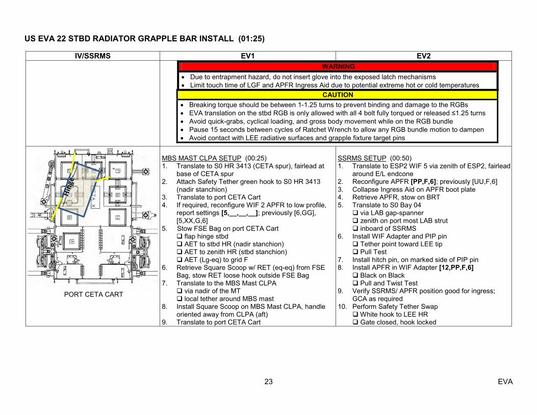
US EVA 22 STBD RADIATOR GRAPPLE BAR INSTALL (01:25)
23 EVA
IV/SSRMS EV1 EV2 WARNING
Due to entrapment hazard, do not insert glove into the exposed latch mechanisms Limit touch time of LGF and APFR Ingress Aid due to potential extreme hot or cold temperatures
CAUTION Breaking torque should be between 1-1.25 turns to prevent binding and damage to the RGBs EVA translation on the stbd RGB is only allowed with all 4 bolt fully torqued or released ≤1.25 turns Avoid quick-grabs, cyclical loading, and gross body movement while on the RGB bundle Pause 15 seconds between cycles of Ratchet Wrench to allow any RGB bundle motion to dampen Avoid contact with LEE radiative surfaces and grapple fixture target pins
PORT CETA CART
MBS MAST CLPA SETUP (00:25) 1. Translate to S0 HR 3413 (CETA spur), fairlead at
base of CETA spur 2. Attach Safety Tether green hook to S0 HR 3413
(nadir stanchion) 3. Translate to port CETA Cart 4. If required, reconfigure WIF 2 APFR to low profile,
report settings [5,__,__,__]; previously [6,GG], [5,XX,G,6]
5. Stow FSE Bag on port CETA Cart flap hinge stbd AET to stbd HR (nadir stanchion) AET to zenith HR (stbd stanchion) AET (Lg-eq) to grid F 6. Retrieve Square Scoop w/ RET (eq-eq) from FSE
Bag, stow RET loose hook outside FSE Bag 7. Translate to the MBS Mast CLPA via nadir of the MT local tether around MBS mast 8. Install Square Scoop on MBS Mast CLPA, handle
oriented away from CLPA (aft) 9. Translate to port CETA Cart
SSRMS SETUP (00:50) 1. Translate to ESP2 WIF 5 via zenith of ESP2, fairlead
around E/L endcone 2. Reconfigure APFR [PP,F,6]; previously [UU,F,6] 3. Collapse Ingress Aid on APFR boot plate 4. Retrieve APFR, stow on BRT 5. Translate to S0 Bay 04 via LAB gap-spanner zenith on port most LAB strut inboard of SSRMS 6. Install WIF Adapter and PIP pin Tether point toward LEE tip Pull Test 7. Install hitch pin, on marked side of PIP pin 8. Install APFR in WIF Adapter [12,PP,F,6] Black on Black Pull and Twist Test 9. Verify SSRMS/ APFR position good for ingress;
GCA as required 10. Perform Safety Tether Swap White hook to LEE HR Gate closed, hook locked
US EVA 22 STBD RADIATOR GRAPPLE BAR INSTALL (01:25)
24 EVA
IV/SSRMS EV1 EV2
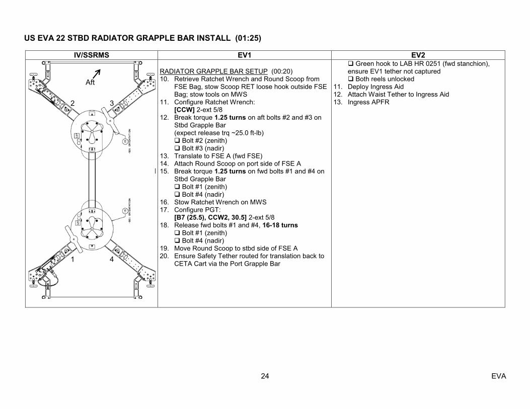
RADIATOR GRAPPLE BAR SETUP (00:20) 10. Retrieve Ratchet Wrench and Round Scoop from
FSE Bag, stow Scoop RET loose hook outside FSE Bag; stow tools on MWS
11. Configure Ratchet Wrench: [CCW] 2-ext 5/8 12. Break torque 1.25 turns on aft bolts #2 and #3 on
Stbd Grapple Bar (expect release trq ~25.0 ft-lb) Bolt #2 (zenith) Bolt #3 (nadir) 13. Translate to FSE A (fwd FSE) 14. Attach Round Scoop on port side of FSE A 15. Break torque 1.25 turns on fwd bolts #1 and #4 on
Stbd Grapple Bar Bolt #1 (zenith) Bolt #4 (nadir) 16. Stow Ratchet Wrench on MWS 17. Configure PGT: [B7 (25.5), CCW2, 30.5] 2-ext 5/8 18. Release fwd bolts #1 and #4, 16-18 turns Bolt #1 (zenith) Bolt #4 (nadir) 19. Move Round Scoop to stbd side of FSE A 20. Ensure Safety Tether routed for translation back to
CETA Cart via the Port Grapple Bar
Green hook to LAB HR 0251 (fwd stanchion), ensure EV1 tether not captured
Both reels unlocked 11. Deploy Ingress Aid 12. Attach Waist Tether to Ingress Aid 13. Ingress APFR
3 2
1 4
Aft

US EVA 22 STBD RADIATOR GRAPPLE BAR INSTALL (01:25)
25 EVA
IV/SSRMS EV1 EV2
RELEASE STBD GRAPPLE BAR FROM POA (00:15) 1. Translate on Port Grapple Bar to POA, perform
fitcheck of PGT w/ 2-ext 5/8 on FSE B Bolt #3 (on the Port Grapple Bar)
2. Stow Ratchet Wrench in FSE Bag 3. Attach Waist Tether to Port Grapple Bar 4. Perform glove inspection 5. Verify PGT: [B7 (25.5), CCW2, 30.5] 2-ext 5/8
RELEASE STBD GRAPPLE BAR FROM POA (00:15) 1. Give SSRMS GO to mnvr to APFR Backoff posn (12
min) GCA SSRMS as reqd 2. Perform glove inspection 3. Install 5/8 (rigid) Socket-7.8 ext Pull test 4. Configure PGT: [A3 (4.8), CW1, 30.5] 7.8-ext 5/8 5. Stow PGT 6. Deconflict Ingress Aid as required 7. RET to Stbd Grapple Bar 8. Hold stbd Grapple Bar corner (near electrical
connector) 6. On EV2 GO, release aft bolts #2 and #3, 16-18
turns Bolt #2 (zenith) Bolt #3 (nadir)
9. Give EV1 GO to release Stbd Grapple Bar bolts #2 and #3
3 2
1 4
Aft
US EVA 22 STBD RADIATOR GRAPPLE BAR INSTALL (01:25)
26 EVA
IV/SSRMS EV1 EV2
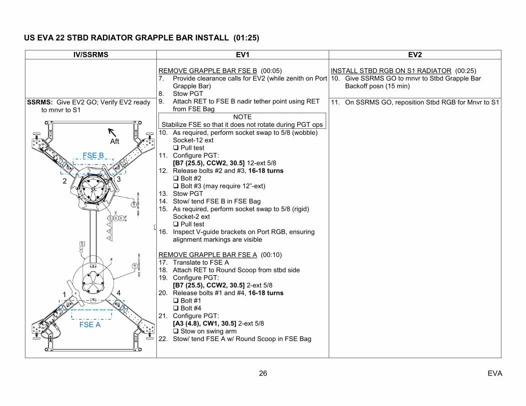
REMOVE GRAPPLE BAR FSE B (00:05) 7. Provide clearance calls for EV2 (while zenith on Port
Grapple Bar) 8. Stow PGT 9. Attach RET to FSE B nadir tether point using RET
from FSE Bag NOTE
Stabilize FSE so that it does not rotate during PGT ops 10. As required, perform socket swap to 5/8 (wobble)
Socket-12 ext Pull test 11. Configure PGT: [B7 (25.5), CCW2, 30.5] 12-ext 5/8 12. Release bolts #2 and #3, 16-18 turns
Bolt #2 Bolt #3 (may require 12‖-ext)
13. Stow PGT 14. Stow/ tend FSE B in FSE Bag 15. As required, perform socket swap to 5/8 (rigid)
Socket-2 ext Pull test 16. Inspect V-guide brackets on Port RGB, ensuring
alignment markings are visible REMOVE GRAPPLE BAR FSE A (00:10) 17. Translate to FSE A 18. Attach RET to Round Scoop from stbd side 19. Configure PGT: [B7 (25.5), CCW2, 30.5] 2-ext 5/8 20. Release bolts #1 and #4, 16-18 turns Bolt #1 Bolt #4 21. Configure PGT: [A3 (4.8), CW1, 30.5] 2-ext 5/8 Stow on swing arm 22. Stow/ tend FSE A w/ Round Scoop in FSE Bag
INSTALL STBD RGB ON S1 RADIATOR (00:25) 10. Give SSRMS GO to mnvr to Stbd Grapple Bar
Backoff posn (15 min)
SSRMS: Give EV2 GO; Verify EV2 ready to mnvr to S1
11. On SSRMS GO, reposition Stbd RGB for Mnvr to S1
3 2
1 4
Aft
FSE B
FSE A
US EVA 22 STBD RADIATOR GRAPPLE BAR INSTALL (01:25)
27 EVA
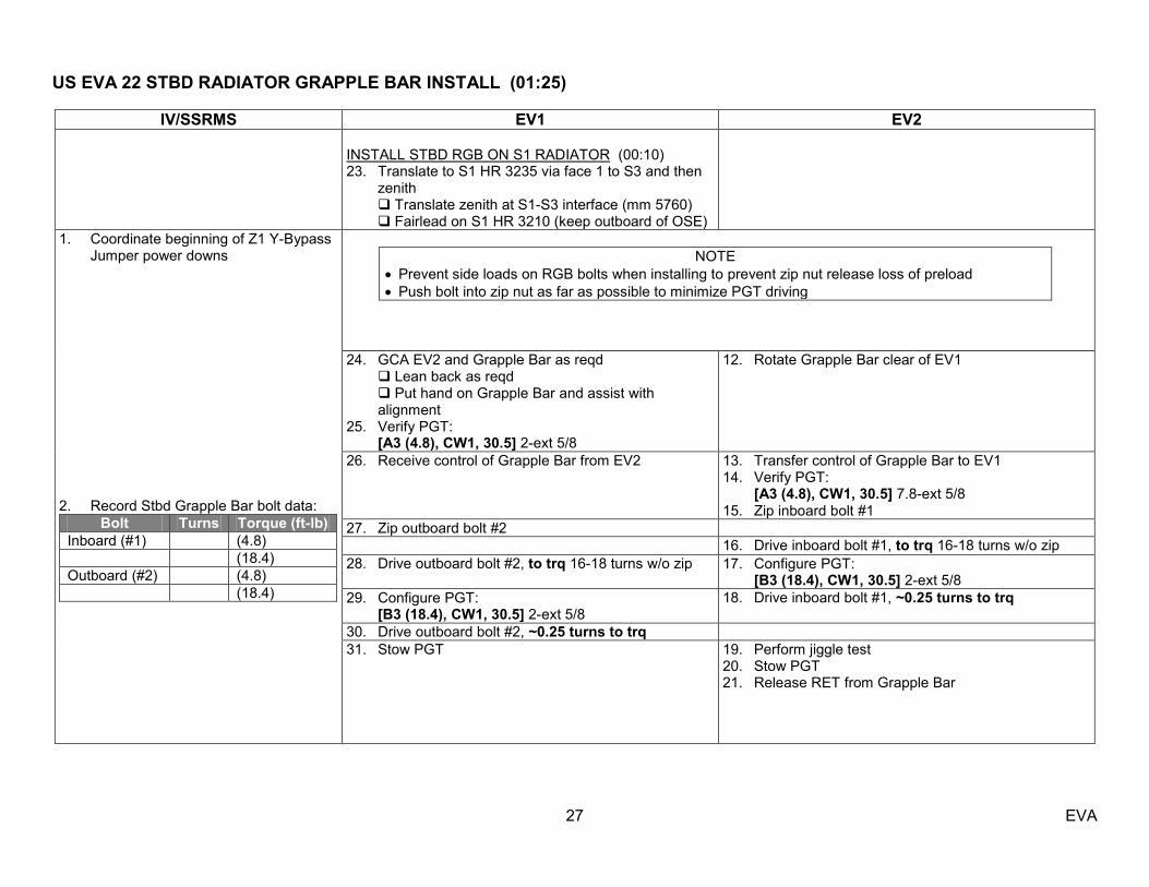
IV/SSRMS EV1 EV2 INSTALL STBD RGB ON S1 RADIATOR (00:10) 23. Translate to S1 HR 3235 via face 1 to S3 and then
zenith Translate zenith at S1-S3 interface (mm 5760) Fairlead on S1 HR 3210 (keep outboard of OSE)
1. Coordinate beginning of Z1 Y-Bypass Jumper power downs
2. Record Stbd Grapple Bar bolt data:
Bolt Turns Torque (ft-lb) Inboard (#1) (4.8) (18.4) Outboard (#2) (4.8) (18.4)
NOTE
Prevent side loads on RGB bolts when installing to prevent zip nut release loss of preload Push bolt into zip nut as far as possible to minimize PGT driving
24. GCA EV2 and Grapple Bar as reqd Lean back as reqd Put hand on Grapple Bar and assist with
alignment 25. Verify PGT: [A3 (4.8), CW1, 30.5] 2-ext 5/8
12. Rotate Grapple Bar clear of EV1
26. Receive control of Grapple Bar from EV2 13. Transfer control of Grapple Bar to EV1 14. Verify PGT: [A3 (4.8), CW1, 30.5] 7.8-ext 5/8 15. Zip inboard bolt #1
27. Zip outboard bolt #2 16. Drive inboard bolt #1, to trq 16-18 turns w/o zip 28. Drive outboard bolt #2, to trq 16-18 turns w/o zip 17. Configure PGT:
[B3 (18.4), CW1, 30.5] 2-ext 5/8 29. Configure PGT: [B3 (18.4), CW1, 30.5] 2-ext 5/8
18. Drive inboard bolt #1, ~0.25 turns to trq
30. Drive outboard bolt #2, ~0.25 turns to trq 31. Stow PGT 19. Perform jiggle test
20. Stow PGT 21. Release RET from Grapple Bar
US EVA 22 MLM POWER CABLE INSTALL / MBS MAST CLPA RETRIEVAL (00:30)
28 EVA
IV/SSRMS EV1 EV2
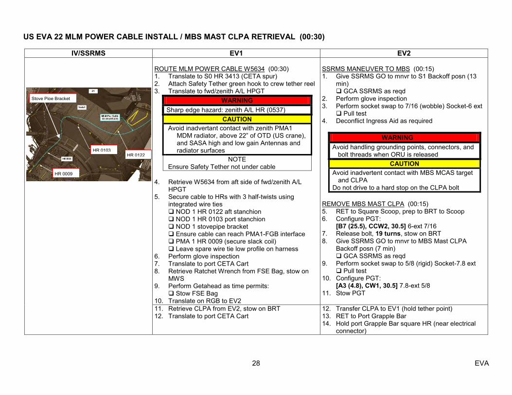
ROUTE MLM POWER CABLE W5634 (00:30) 1. Translate to S0 HR 3413 (CETA spur) 2. Attach Safety Tether green hook to crew tether reel 3. Translate to fwd/zenith A/L HPGT
WARNING Sharp edge hazard: zenith A/L HR (0537)
CAUTION Avoid inadvertant contact with zenith PMA1
MDM radiator, above 22‖ of OTD (US crane), and SASA high and low gain Antennas and radiator surfaces
NOTE Ensure Safety Tether not under cable
4. Retrieve W5634 from aft side of fwd/zenith A/L
HPGT 5. Secure cable to HRs with 3 half-twists using
integrated wire ties NOD 1 HR 0122 aft stanchion NOD 1 HR 0103 port stanchion NOD 1 stovepipe bracket Ensure cable can reach PMA1-FGB interface PMA 1 HR 0009 (secure slack coil) Leave spare wire tie low profile on harness 6. Perform glove inspection 7. Translate to port CETA Cart 8. Retrieve Ratchet Wrench from FSE Bag, stow on
MWS 9. Perform Getahead as time permits: Stow FSE Bag 10. Translate on RGB to EV2
SSRMS MANEUVER TO MBS (00:15) 1. Give SSRMS GO to mnvr to S1 Backoff posn (13
min) GCA SSRMS as reqd 2. Perform glove inspection 3. Perform socket swap to 7/16 (wobble) Socket-6 ext Pull test 4. Deconflict Ingress Aid as required
WARNING Avoid handling grounding points, connectors, and
bolt threads when ORU is released CAUTION
Avoid inadvertent contact with MBS MCAS target and CLPA
Do not drive to a hard stop on the CLPA bolt REMOVE MBS MAST CLPA (00:15) 5. RET to Square Scoop, prep to BRT to Scoop 6. Configure PGT: [B7 (25.5), CCW2, 30.5] 6-ext 7/16 7. Release bolt, 19 turns, stow on BRT 8. Give SSRMS GO to mnvr to MBS Mast CLPA
Backoff posn (7 min) GCA SSRMS as reqd 9. Perform socket swap to 5/8 (rigid) Socket-7.8 ext Pull test 10. Configure PGT: [A3 (4.8), CW1, 30.5] 7.8-ext 5/8 11. Stow PGT
11. Retrieve CLPA from EV2, stow on BRT 12. Translate to port CETA Cart
12. Transfer CLPA to EV1 (hold tether point) 13. RET to Port Grapple Bar 14. Hold port Grapple Bar square HR (near electrical
connector)
HR 0009
HR 0122 HR 0103
Stove Pipe Bracket
US EVA 22 PORT RADIATOR GRAPPLE BAR INSTALL (00:40)
29 EVA
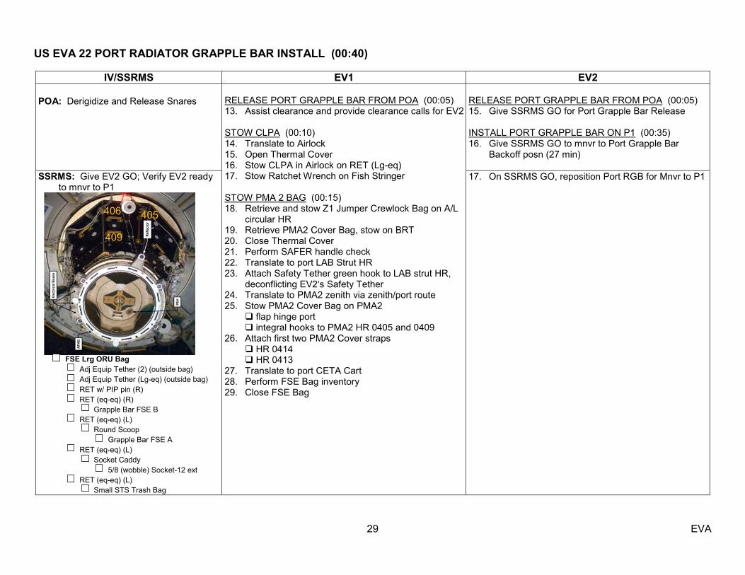
IV/SSRMS EV1 EV2 POA: Derigidize and Release Snares
RELEASE PORT GRAPPLE BAR FROM POA (00:05) 13. Assist clearance and provide clearance calls for EV2 STOW CLPA (00:10) 14. Translate to Airlock 15. Open Thermal Cover 16. Stow CLPA in Airlock on RET (Lg-eq) 17. Stow Ratchet Wrench on Fish Stringer STOW PMA 2 BAG (00:15) 18. Retrieve and stow Z1 Jumper Crewlock Bag on A/L
circular HR 19. Retrieve PMA2 Cover Bag, stow on BRT 20. Close Thermal Cover 21. Perform SAFER handle check 22. Translate to port LAB Strut HR 23. Attach Safety Tether green hook to LAB strut HR,
deconflicting EV2‘s Safety Tether 24. Translate to PMA2 zenith via zenith/port route 25. Stow PMA2 Cover Bag on PMA2 flap hinge port integral hooks to PMA2 HR 0405 and 0409 26. Attach first two PMA2 Cover straps HR 0414 HR 0413 27. Translate to port CETA Cart 28. Perform FSE Bag inventory 29. Close FSE Bag
RELEASE PORT GRAPPLE BAR FROM POA (00:05) 15. Give SSRMS GO for Port Grapple Bar Release INSTALL PORT GRAPPLE BAR ON P1 (00:35) 16. Give SSRMS GO to mnvr to Port Grapple Bar
Backoff posn (27 min)
SSRMS: Give EV2 GO; Verify EV2 ready to mnvr to P1
FSE Lrg ORU Bag Adj Equip Tether (2) (outside bag) Adj Equip Tether (Lg-eq) (outside bag) RET w/ PIP pin (R) RET (eq-eq) (R) Grapple Bar FSE B RET (eq-eq) (L) Round Scoop Grapple Bar FSE A RET (eq-eq) (L) Socket Caddy 5/8 (wobble) Socket-12 ext RET (eq-eq) (L) Small STS Trash Bag
17. On SSRMS GO, reposition Port RGB for Mnvr to P1
406 405
409

US EVA 22 PORT RADIATOR GRAPPLE BAR INSTALL (00:40)
30 EVA
IV/SSRMS EV1 EV2 MCC-H: Consumables Update
INSTALL PORT GRAPPLE BAR ON P1 (00:10) 30. Translate to P1 HR 3367 via face 1 Translate nadir at FHRC (mm 9150) Fairlead on P1 HR 3651 (face 6 HR)
1. Record Stbd Grapple Bar bolt data:
Bolt Turns Torque (ft-lb) Inboard (#1) (4.8) (18.4) Outboard (#2) (4.8) (18.4)
NOTE
Prevent side loads on RGB bolts when installing to prevent zip nut release loss of preload Push bolt into zip nut as far as possible to minimize PGT driving
31. GCA EV2 and Grapple Bar as reqd Lean back as reqd Put hand on Grapple Bar and assist with
alignment 32. Configure PGT: [A3 (4.8), CW1, 30.5] 2-ext 5/8
18. Rotate Grapple Bar clear of EV1
33. Receive control of Grapple Bar from EV2 19. Transfer control of Grapple Bar to EV1 20. Configure PGT: [A3 (4.8), CW1, 30.5] 7.8-ext 5/8 21. Zip inboard bolt #1
34. Zip outboard bolt #2 22. Drive inboard bolt #1, to trq 16-18 turns w/o zip 35. Drive outboard bolt #2, to trq 16-18 turns w/o zip 23. Configure PGT:
[B3 (18.4), CW1, 30.5] 2-ext 5/8 36. Configure PGT: [B3 (18.4), CW1, 30.5] 2-ext 5/8
24. Drive inboard bolt #1, ~0.25 turns to trq
37. Drive outboard bolt #2, ~0.25 turns to trq 38. Stow PGT 39. Perform glove inspection
25. Perform jiggle test 26. Stow PGT 27. Release RET from Grapple Bar

US EVA 22 Z1 Y-BYPASS JUMPER INSTALL (01:00) / SSRMS CLEANUP (00:55)
31 EVA
IV/SSRMS EV1 EV2 SSRMS: Verify EV2 ready to mnvr into S0 1. Verify Y-Bypass Jumper Inhibits
complete
RETRIEVE Z1 Y-BYPASS JUMPERS (00:25) 1. Translate to port LAB strut HR 2. Attach Safety Tether green hook to crew tether reel 3. Transfer to A/L circular HR 4. Retrieve Z1 Jumper Crewlock Bag with RET (Lg-eq) 5. Translate aft to Aux Bag#1 on NOD1 aft endcone 6. Open Aux Bag #1 ¼-turn fasteners (2); Velcro 7. RET to Z1-Jumpers (2) using 2 tether points, release
Velcro strap, stow between MWS T-bar and DCM Jumper Z1-005/ 4B– (nadir) Jumper Z1-006/ 3B – (zenith) 8. Close Aux Bag, secure ¼-turn fasteners (2) and
Velcro 9. Translate to port Z1 via zenith NOD1 endcone
CAUTION Avoid contact with PCU cathode and HCA ports,
heat pipe radiators, WETA, and NOD1 CETA light
NOTE Missing label on zenith X2 J3 Patch Panel jack
10. Pitch IAPFR out of worksite, report settings
[6,__,__,__]; previously [6,PP,F,12] 11. Stow Z1 Jumper Crewlock Bag between IAPFR and
Z1 HR 6020 12. Perform worksite familiarization 005 Patch Panel (Nadir, fwd connectors) W10 Cable Harness (attached to J1) 4B RPCM Panel (Nadir, aft connectors) 006 Patch Panel (Zenith, fwd connectors) W05 Cable Harness (DO NOT DEMATE)
WARNING Do not demate Cable W05 Connectors P1 or P2 as
these connections are not inhibitied
SSRMS CLEANUP (00:55) 1. Give SSRMS GO to mnvr to P1 Backoff posn (13
min) 2. Perform socket swap to 7/16 (wobble) Socket-6 ext Pull test 3. GCA SSRMS as reqd Brakes on SSRMS 4. Egress APFR 5. Perform Safety Tether Swap Green hook from LAB HR 0251 to crew tether reel Gate closed, hook locked White hook from LEE HR to anchor reel Gate closed, hook locked Both reels unlocked 6. Remove APFR from WIF Adapter, stow on BRT 7. Verify all tethers and hardware free from SSRMS 8. Give SSRMS GO to mnvr to SSRMS Park posn 9. Translate to ESP2 WIF 5 10. Install APFR in port ESP2 WIF 5 [6,UU,F,6] Black on Black Pull and Twist Test Telescope in and collapse Ingress Aid against
boot plate 11. Perform glove inspection

US EVA 22 Z1 Y-BYPASS JUMPER INSTALL (01:00) / SSRMS CLEANUP (00:55)
32 EVA
IV/SSRMS EV1 EV2
2. Give SPARTAN GO to repower DDCU
converter
INSTALL Z1 Y-JUMPER PART 1 (NADIR) (00:20) 13. Retrieve GTEC, attach to Z1 HR 6019 via integral eq
hook (in center of diagonal HR) 14. Perform the following mate/demates on Nadir Y-
Bypass Jumper Z1-005/4B and Harness W10: Aft connectors (Z1-4B SPDA Nadir RPCM Panel): W10 P2 | 4B RPCM Panel J1 W10 P2 | Dust Cap (Crewlock Bag) Insert W10 P2 in GTEC on Z1 HR 6019 (4B) Jumper P1 | 4B RPCM Panel J1 Fwd connectors (Z1-005 Nadir X1 Patch Panel): Tether 005 Patch Panel J2 and J3 Dust Caps
(2), using Adj Equip Tether from Crewlock Bag Dust cap | 005 Patch Panel J2 Dust cap | 005 Patch Panel J3 W10 P1 | 005 Patch Panel J1 W10 P1 | 005 Patch Panel J3 Jumper P3 | 005 Patch Panel J1 Jumper P2 | 005 Patch Panel J2
Final Config (Z1-4B SPDA)
Initial Config
US EVA 22 Z1 Y-BYPASS JUMPER INSTALL (01:00) / SSRMS CLEANUP (00:55)
33 EVA
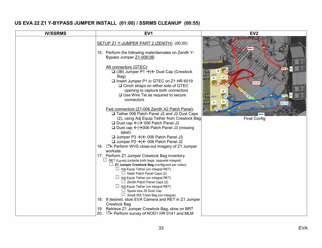
IV/SSRMS EV1 EV2 SETUP Z1 Y-JUMPER PART 2 (ZENITH) (00:20) 15. Perform the following mate/demates on Zenith Y-
Bypass Jumper Z1-006/3B: Aft connectors (GTEC): (3B) Jumper P1 | Dust Cap (Crewlock
Bag) Insert Jumper P1 in GTEC on Z1 HR 6019 Cinch straps on either side of GTEC
opening to capture both connectors Use Wire Tie as required to secure
connectors Fwd connectors (Z1-006 Zenith X2 Patch Panel): Tether 006 Patch Panel J2 and J3 Dust Caps
(2), using Adj Equip Tether from Crewlock Bag Dust cap | 006 Patch Panel J2 Dust cap |006 Patch Panel J3 (missing
label) Jumper P3 | 006 Patch Panel J3 Jumper P2 | 006 Patch Panel J2 16. Perform WVS close-out imagery of Z1 Jumper
worksite 17. Perform Z1 Jumper Crewlock Bag inventory RET (Lg-eq) (outside both bags, opposite integral) Z1 Jumper Crewlock Bag (configured per video) Adj Equip Tether (on integral RET) Nadir Patch Panel Caps (2) Adj Equip Tether (on integral RET) Zenith Patch Panel Caps (2) Adj Equip Tether (on integral RET) Spare size 25 Dust Cap Small ISS Trash Bag (on integral) 18. If desired, stow EVA Camera and RET in Z1 Jumper
Crewlock Bag 19. Retrieve Z1 Jumper Crewlock Bag, stow on BRT 20. Perform survey of NOD1 HR 0141 and MLM
Final Config
US EVA 22 Z1 Y-BYPASS JUMPER INSTALL (01:00) / SSRMS CLEANUP (00:55)
34 EVA
IV/SSRMS EV1 EV2 Ethernet jack
21. Translate to A/L 22. Open Thermal Cover 23. Stow Z1 Jumper Crewlock Bag in the A/L aft side 24. Stow PGT on Fish Stringer 25. Close Thermal Cover 26. Perform SAFER handle check 27. Perform glove inspection

US EVA 22 PMA 2 COVER INSTALL (00:35/00:40)
35 EVA
IV/SSRMS EV1 EV2
INSTALL PMA2 COVER (00:35) 1. Translate to LAB HR 0263 via CETA spur and the
LAB zenith/port route 2. Release and attach green hook on LAB HR 0263 3. Translate to PMA 2 zenith
INSTALL PMA2 COVER (00:40) 1. Translate to LAB HR 0264 via zenith/stbd route 2. Release and attach green hook on LAB HR 0264 3. Translate to PMA2 zenith
WARNING Avoid contact with potential sharp edges on NOD2 fwd HR 0327, PMA2 nadir HR 0417, zenith PMA2
surface, APAS mating surface, reflector, and umbilical launch restraints NOTE
Allow for extra slack in first few Cover straps to ensure full coverage of PMA2 mating surface
4. Assist EV2 as required 4. Open PMA 2 Cover Bag and release Adj Equip Tether and RET (Lg-eq)
5. Align Cover cut-out with APAS reflector 6. Continue to unfold PMA2 cover, while attaching
Velcro straps on fwd circumferential HRs 0412
0411 0410
7. Work back zenith toward bag, ensuring at least a ½
inch overlap, retightening straps as required and perform WVS close-out imagery of PMA2 cover
0410 0411 0412 0413
8. Perform glove inspection 9. Translate to LAB HR 0263 10. Attach Safety Tether green hook to crew tether reel 11. Translate to port CETA Cart 12. Stow FSE Bag on BRT 13. Translate to Airlock endcone HR 0564 14. Stow FSE Bag on Airlock HR 0564 and 0567, using
Adj Equip Tethers (3)
5. Align Cover cut-out with APAS reflector 6. Continue to unfold PMA2 cover, while attaching
Velcro straps on aft circumferential HRs 0415 0418 0416 0417
7. Work back zenith toward bag, ensuring at least a ½ inch overlap, retightening straps as required and perform WVS close-out imagery of PMA2 cover
0417 0416 0418 0415 0414
8. Perform glove inspection 9. Perform PMA2 Cover Bag inventory PMA 2 Cover Bag RET (eq-eq) (bottom of bag) Adj Equip Tether (D-rings to RET hook) Small ISS Trash Bag Wire Tie Caddy (w/ 9 short) Fish Stringer Tether (Lg hooks to bottom of bag) 1553 Cable (secure with non-hinge-side Velcro strap) 1553 Dust Caps (hooks 1 & 2) MLM Ethernet Cable (secure with hinge-side Velcro strap)
US EVA 22 PMA 2 COVER INSTALL (00:35/00:40)
36 EVA
IV/SSRMS EV1 EV2 RET (Lg-eq) Adj Equip Tether (eq-eq) (2) 10. Retrieve PMA2 Cover Bag, stow on BRT 11. Translate to LAB HR 0263 12. Attach Safety Tether green hook to crew tether reel
US EVA 22 CLEANUP/INGRESS (00:30)
37 EVA
IV/SSRMS EV1 EV2
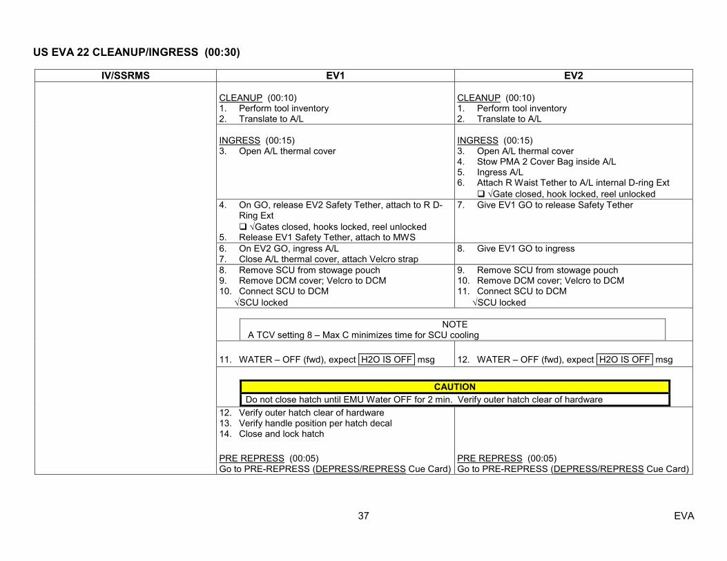
CLEANUP (00:10) 1. Perform tool inventory 2. Translate to A/L
CLEANUP (00:10) 1. Perform tool inventory 2. Translate to A/L
INGRESS (00:15) 3. Open A/L thermal cover
INGRESS (00:15) 3. Open A/L thermal cover 4. Stow PMA 2 Cover Bag inside A/L 5. Ingress A/L 6. Attach R Waist Tether to A/L internal D-ring Ext Gate closed, hook locked, reel unlocked
4. On GO, release EV2 Safety Tether, attach to R D-Ring Ext
Gates closed, hooks locked, reel unlocked 5. Release EV1 Safety Tether, attach to MWS
7. Give EV1 GO to release Safety Tether
6. On EV2 GO, ingress A/L 7. Close A/L thermal cover, attach Velcro strap
8. Give EV1 GO to ingress
8. Remove SCU from stowage pouch 9. Remove DCM cover; Velcro to DCM 10. Connect SCU to DCM SCU locked
9. Remove SCU from stowage pouch 10. Remove DCM cover; Velcro to DCM 11. Connect SCU to DCM SCU locked
NOTE
A TCV setting 8 – Max C minimizes time for SCU cooling
11. WATER – OFF (fwd), expect H2O IS OFF msg
12. WATER – OFF (fwd), expect H2O IS OFF msg
CAUTION
Do not close hatch until EMU Water OFF for 2 min. Verify outer hatch clear of hardware
12. Verify outer hatch clear of hardware 13. Verify handle position per hatch decal 14. Close and lock hatch
PRE REPRESS (00:05) Go to PRE-REPRESS (DEPRESS/REPRESS Cue Card)
PRE REPRESS (00:05) Go to PRE-REPRESS (DEPRESS/REPRESS Cue Card)

US EVA 22 GETAHEADS
38 EVA
EVA Get-ahead Tasks (Priority Order)
Duration 1EV / 2EV
Inhibits
1. PMA 2 Cover Bag (MLM/ 1553 Cables) Tempstow 00:20 / NA N/A 2. MLM Ethernet Cable Install 00:35 / NA RSOS 3. PDGF FOD Removal 00:20 / NA RSOS 4. PDGF 1553 Cable Install 00:30 / NA RSOS 5. APFR/TS Relocate NA / 00:20 Port TRRJ lock

US EVA 22 GETAHEAD – PMA 2 COVER BAG (MLM/ 1553 CABLES) TEMPSTOW (00:20)
39 EVA
IV/SSRMS EV1
TEMPSTOW PMA 2 COVER BAG (MLM/ 1553 CABLES) (00:20) 1. Translate to Node 1 HR 0103 via stbd route; if desired, drop green hook on Node 1 HR (fairlead). 2. Stow PMA2 Cover Bag Hinge stbd Node 1 HR 0102 (port Stanchion) Node 1 HR 0104 (stbd Stanchion) 3. Perform glove inspection

US EVA 22 GETAHEAD – MLM ETHERNET CABLE INSTALL (00:40)
40 EVA
IV/SSRMS EV1
NODE 1 CONNECTION (00:15)
1. Retrieve MLM Ethernet Cable from PMA2 Cover Bag 2. Translate to Node 1 Fwd endcone HR 0141 (existing Ethernet pigtail),
staying zenith of CETA Light 3. Release Wire Ties labeled HR 0141/START & HR 0140/ FIRST TY 4. RET to J2 cap on existing Ethernet pigtail (release Wire Tie if req‘d 5. Pigtail (W0939) J2 | P2/W5946 (MLM Ethernet) 6. Briefly describe worksite access near MMOD shield C1-01 (future NOD3
IFHX worksite under NOD3 MMOD shield C1-01) NODE 1 ROUTING TO FGB (0:20) 7. Secure cable to HRs with 1 pre-integrated Short Wire Tie each, 3 twists.
Verify Safety Tether is clear before securing each Wire Tie Node 1 HR 0141 (optional) (If not installed, make low profile) Node1 HR 0140/ FIRST TY nadir stanchion (Circumferential HR) Node 1 HR 0129 fwd stanchion (Horiz HR) Node 1 HR 0121 aft stanchion (Horiz HR) Node 1 HR 0105 zenith stanchion (Circumferential HR) PMA1 STOVEPIPE (Wire Tie label ―HR STOVEPIPE‖) PMA1 TA C-7 (Wire Tie label ―TA-C7‖) PMA1 HR 0010 (nadir of Crane) FGB HR 1050 (Circumferential HR) – coil & restrain extra cable in
this Wire Tie zenith on HR away from FGB PDGF
WARNING
Avoid contact with grapple fixture target, target pin, connector doors, and PDGF curvic coupling (teeth)
Avoid contact with FGB sun sensors (possible sharp edges)
CAUTION Avoid contact with zenith PMA1 MDM and above 22" of EVA crane
(OTD)
NOTE Do not release MLM Ethernet Cable Wire Tie labeled ―PIGTAIL‖. This
Wire Tie secures 4 pigtails to main cable and is not used to secure cable to structure
Verify Safety Tether is clear before securing each Wire Tie
US EVA 22 GETAHEAD – MLM ETHERNET CABLE INSTALL (00:40)
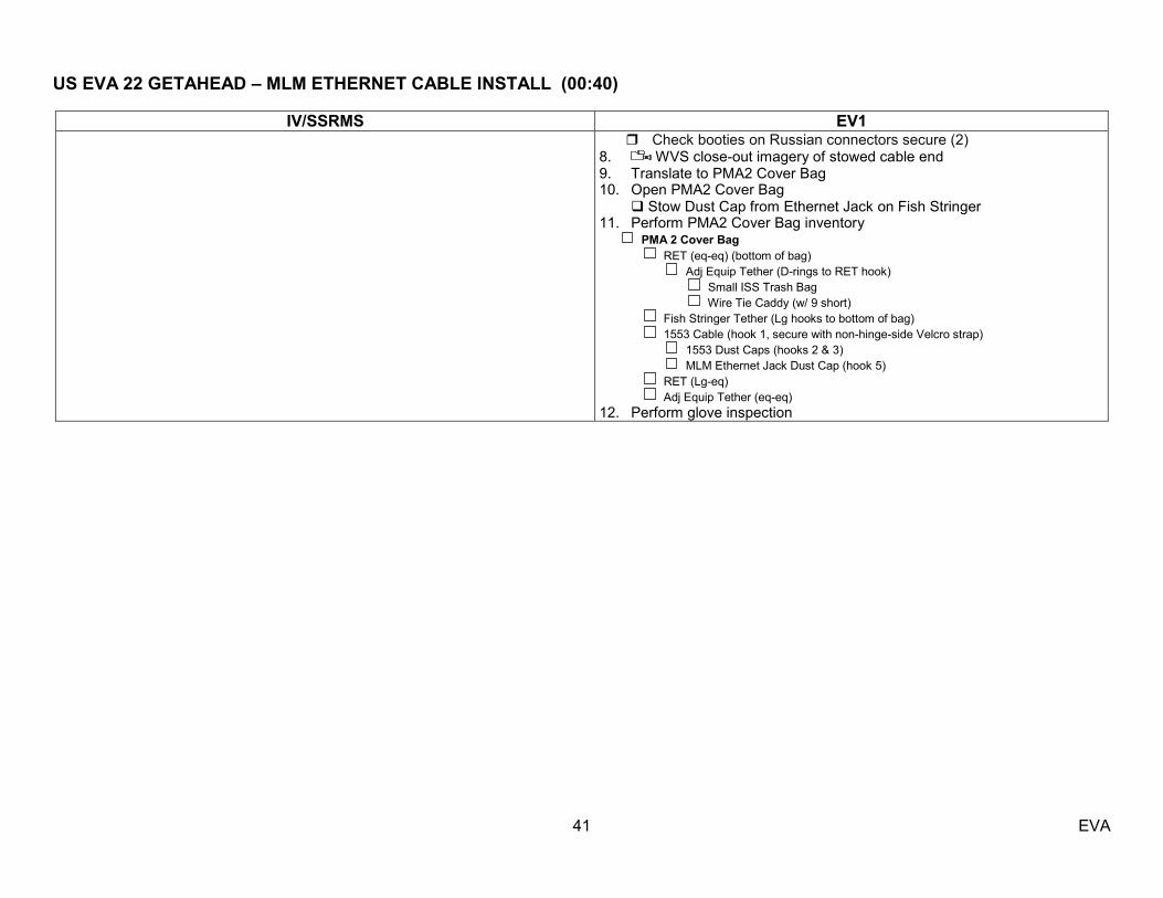
41 EVA
IV/SSRMS EV1 Check booties on Russian connectors secure (2)
8. WVS close-out imagery of stowed cable end 9. Translate to PMA2 Cover Bag 10. Open PMA2 Cover Bag
Stow Dust Cap from Ethernet Jack on Fish Stringer 11. Perform PMA2 Cover Bag inventory PMA 2 Cover Bag RET (eq-eq) (bottom of bag) Adj Equip Tether (D-rings to RET hook) Small ISS Trash Bag Wire Tie Caddy (w/ 9 short) Fish Stringer Tether (Lg hooks to bottom of bag) 1553 Cable (hook 1, secure with non-hinge-side Velcro strap) 1553 Dust Caps (hooks 2 & 3) MLM Ethernet Jack Dust Cap (hook 5) RET (Lg-eq) Adj Equip Tether (eq-eq) 12. Perform glove inspection

US EVA 22 GETAHEAD – FGB PDGF FOD REMOVAL (00:20)
42 EVA
IV/SSRMS EV1
1. FGB PDGF inhibits in place
Crew hook on waist tether used to open PDGF Electrical
Connector
FGB PDGF FOD REMOVAL (0:20) 1. MCC Coord Only Verify Inhibits
2. Translate zenith of PDGF 3. If needed, BRT to HR, (else MWS EE to PDGF tether point) 4. Insert large crew hook in zenith/fwd electrical connector doors (orient hook perpendicular to
doors so hook does not damage pins
5. FOD Removal Inspect grounding wire & attachment point (for damage or potential snag concerns for wire slack removal) Open zenith/forward PDGF MLI Pull grounding wire slack out of PDGF housing Secure grounding wire slack between PDGF housing and MLI Using crew hook on Waist Tether, verify zenith/fwd electrical connector clear of grounding wire
6. WVS close-out imagery and crew inspection inside PDGF connector door 7. Perform glove inspection
WARNING
Avoid contact with grapple fixture target, target pin, and PDGF curvic coupling (teeth) Avoid contact with FGB sun sensors (possible sharp edges)
CAUTION Avoid contact with zenith PMA1 MDM and above 22" of EVA crane stanchion
NOTE VSC cover should not be used as a translation aid or handhold (attached only by detents
and Russian Tether)
US EVA 22 GETAHEAD – PDGF 1553 CABLE INSTALL (00:30)
43 EVA
IV/SSRMS EV1
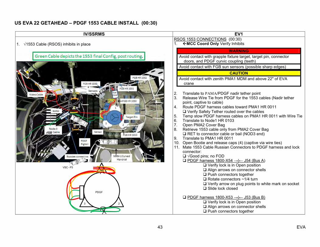
1. 1553 Cable (RSOS) inhibits in place
RSOS 1553 CONNECTIONS (00:30) 1. MCC Coord Only Verify Inhibits
2. Translate to /PDGF nadir tether point 3. Release Wire Tie from PDGF for the 1553 cables (Nadir tether
point, captive to cable) 4. Route PDGF harness cables toward PMA1 HR 0011
Verify Safety Tether routed over the cables 5. Temp stow PDGF harness cables on PMA1 HR 0011 with Wire Tie 6. Translate to Node1 HR 0103 7. Open PMA2 Cover Bag 8. Retrieve 1553 cable only from PMA2 Cover Bag
RET to connector cable or bail (NOD3 end) 9. Translate to PMA1 HR 0011 10. Open Bootie and release caps (4) (captive via wire ties) 11. Mate 1553 Cable Russian Connectors to PDGF harness and lock
connector: Good pins; no FOD PDGF harness 1800-X54 →|← J54 (Bus A)
Verify lock is in Open position Align arrows on connector shells Push connectors together Rotate connectors ~1/4 turn Verify arrow on plug points to white mark on socket Slide lock closed
PDGF harness 1800-X53 →|← J53 (Bus B)
Verify lock is in Open position Align arrows on connector shells Push connectors together
WARNING
Avoid contact with grapple fixture target, target pin, connector doors, and PDGF curvic coupling (teeth)
Avoid contact with FGB sun sensors (possible sharp edges) CAUTION
Avoid contact with zenith PMA1 MDM and above 22" of EVA crane
PDGF
1
3 2
P7P5
P6
P8
VSC – P2
FGB J19
FGB J18
VSC - P3
VSC - P4
1553 - X54
1553 - X53

US EVA 22 GETAHEAD – PDGF 1553 CABLE INSTALL (00:30)
44 EVA
IV/SSRMS EV1
Rotate connectors ~1/4 turn Verify arrow on plug points to white mark on socket Slide lock closed
12. Secure FPP booties around 1553/PDGF harness connections 13. Wire tie to PMA1 HR 0011 14. Route cable nadir/port to Node 3 connector panel
Stove Pipe (BRT Wire Tie) NOD1 HR 0118 (pre-integrated Wire Tie) leave cable bundle on NOD1 HR 0118
15. Translate to PMA2 Cover Bag 16. Perform PMA2 Cover Bag inventory PMA 2 Cover Bag RET (eq-eq) (bottom of bag) Adj Equip Tether (D-rings to RET hook) Small ISS Trash Bag Wire Tie Caddy (w/ 9 short) Fish Stringer Tether (Lg hooks to bottom of bag) 1553 Dust Caps (hooks 2 & 3) MLM Ethernet Jack Dust Cap (hook 5) RET (Lg-eq) Adj Equip Tether (eq-eq) 17. Perform glove inspection
US EVA 22 GETAHEAD – APFR/ TS RELOCATE (00:30)
45 EVA
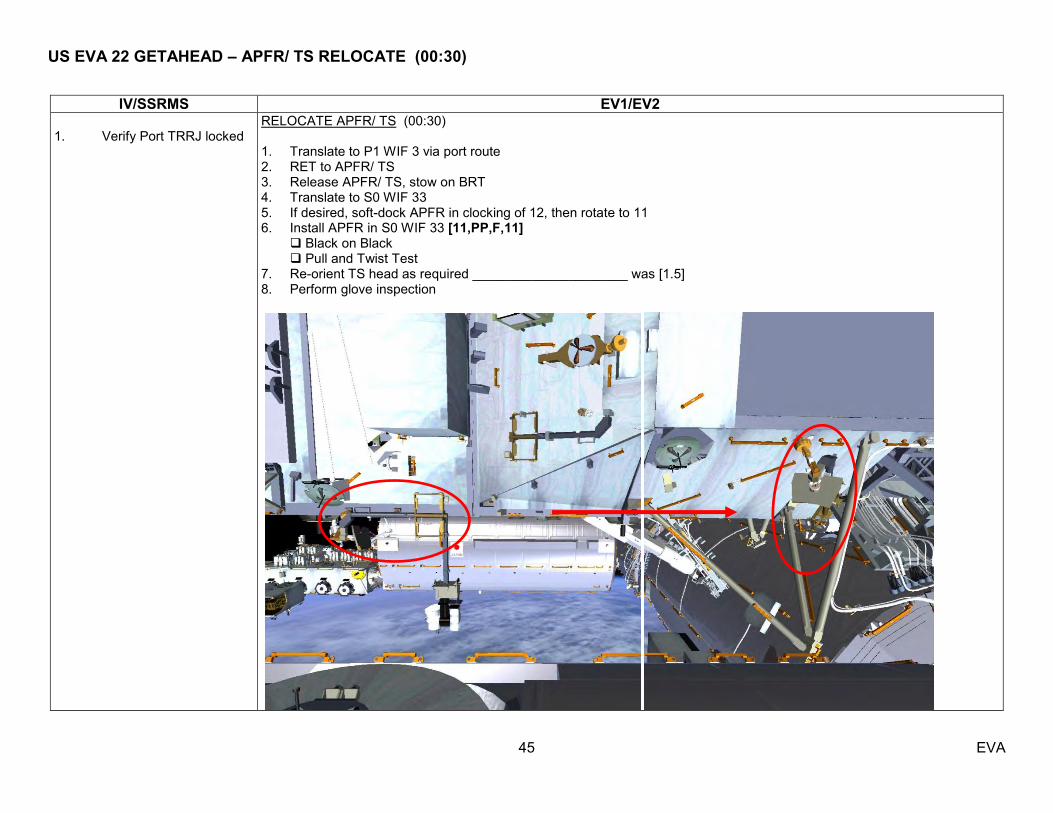
IV/SSRMS EV1/EV2 1. Verify Port TRRJ locked
RELOCATE APFR/ TS (00:30) 1. Translate to P1 WIF 3 via port route 2. RET to APFR/ TS 3. Release APFR/ TS, stow on BRT 4. Translate to S0 WIF 33 5. If desired, soft-dock APFR in clocking of 12, then rotate to 11 6. Install APFR in S0 WIF 33 [11,PP,F,11] Black on Black Pull and Twist Test 7. Re-orient TS head as required _____________________ was [1.5] 8. Perform glove inspection

US EVA 22 TIME CONSIDERATIONS
46 EVA
Bingo Times – NLT Start PET for tasks – to not extend Stbd RGB (assuming drop PMA2 Cover and leave a little pad)
o 2:00 – based on 6:15 EVA o 2:15 – based on 6:30 EVA
Mast CLPA (assuming drop PMA2 Cover and no APFR cleanup on SSRMS)) o 4:00 – based on 6:15 EVA o 4:15 – based on 6:30 EVA
Port RGB Install (assuming drop PMA 2 Cover and no APFR cleanup on SSRMS) o 4:30 – based on 6:15 EVA o 4:45 – based on 6:30 EVA
Z1 Jumper (assuming drop PMA2 Cover) o 4:55 – based on 6:15 EVA o 5:10 – based on 6:30 EVA
*rationale for using 45 min to replace the PMA 2 Cover Task is from the large pad used on both PMA2 Cover and Cleanup/Ingress Tasks **deleting APFR cleanup from the SSRMS results in a 15 min time savings Thermal Clock
SGTRC failed and spare MISSE 8 No other Thermal Clocks Applicable
Other Time Considerations:
If EV1 is 15 min ahead or more of EV2 after the SGTRC R&R consider MLM Power Cable Routing Task or photo ops If EV1 is 15 min ahead or more of EV2 after MLM Power Cable consider retrieving Z1-Jumpers
US EVA 22 TASK DATA – SGTRC
47 EVA
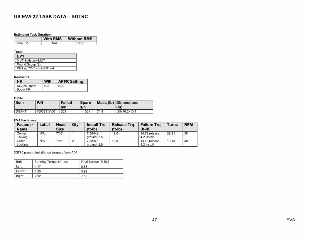
Estimated Task Duration:
With RMS Without RMS One EV N/A 01:00
Tools:
EV1 MUT-Ballstack-MUT Round Scoop (2) PGT w/ 7/16‖ socket-9‖ ext
Restraints:
HR WIF APFR Setting SGANT spare Boom HR
N/A N/A
ORUs: Item P/N Failed
s/n Spare s/n
Mass (lb) Dimensions (in)
SGANT 10033317-501 003 001 74.8 25x16.2x10.1 EVA Fasteners:
Fastener Name
Label Head Size
Qty Install Trq (ft-lb)
Release Trq (ft-lb)
Failure Trq (ft-lb)
Turns RPM
Center Jacking
N/A 7/16‖ 1 7.58-8.8 ground; 2.5
12.0 14.73 release, 4.2 install
28-31 30
Outer Locking
N/A 7/16‖ 2 7.58-8.8 ground; 2.5
12.0 14.73 release, 4.2 install
10-13 30
SGTRC ground installation torques from ADP
Bolt Running Torque (ft-lbs) Final Torque (ft-lbs)
Left 4.17 8.83 Center 1.25 5.92 Right 2.92 7.58

US EVA 22 TASK DATA – SGTRC
48 EVA
Warning: 1.
Caution:
1. Avoid contact with heat pipe radiators, and SASA high and low gain antennas and radiator surfaces, and SGTRC-2 Z93 paint – EV&CS 2. Do not use the connector bracket for stability during nom ops – S&M 3. The AGIT bolts on the SGTRC ORU launching on ULF-4 were identified to be undersized and the maximum torque of 39 ft-lbf must not be exceeded in order to prevent rounding of the bolt head
– S&M Note:
1. Failure Mode for Release = Torsional Shear Shank Failure; Failure Mode for Install = Combined Loading – S&M 2. No anti-rotation device nor soft dock – EV&CS 3. Bolts were installed with lock patch applied to threads on failed unit only. There was no lock patch installed on the spare SGTRC – S&M 4. Installation is highly dependent on running torque, due to the presence of lock patch. In order to overcome higher running torque due to residual lock patch the torque can be incrementally
increased. The torque must be increased one PGT setting at a time to a maximum of 22.0 ft-lbf – S& 5. B7 (25.5 ft-lbs) can be used for 1 turn to break torque on the fastener – S&M 6. The WR-62 waveguide interface is the same as the SGANT installed on ULF-4. The SGANT was installed on the Boom and the crew could see there was a small gap and ability to wiggle the
SGANT. This interface has a very tight tolerance to allow data to pass at that Ku-Band frequencies (15 Ghz). S&M and C&T determed that higher torque values were needed, and went back and tightened the bolts. This resolved the issue. The original torque values were conservative because they were worried about stripping the bolts. The SGTRC has similar guide pins and a tight tolerance, that are all driven by the torque values on the 3 6B bolts – NASA C&T
7. Bottom of TRC and the receptacle plate is okay to touch – EV&CS 8. IVA Cover returned on ULF-4 - EV&CS 9. No SGANT Masking concerns with this task (SGTRC R&R) – C&T 10. No PRs nor IFIs exist – EV&CS 11. Approval to leave 9‖ socet in ISS Small Trash Bag (one time approval) – MER Tools
Timeline Considerations:
1. Plan is to not checkout SGTRC#2 prior to Z1 Y-Bypass Jumper Install – MOD

US EVA 22 TASK DATA – SGTRC
49 EVA
US EVA 22 TASK DATA – SGTRC
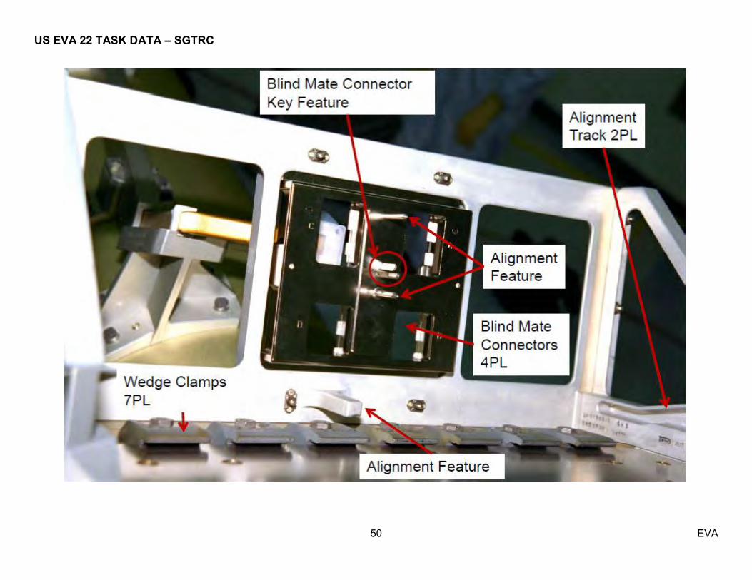
50 EVA
US EVA 22 TASK DATA – SGTRC
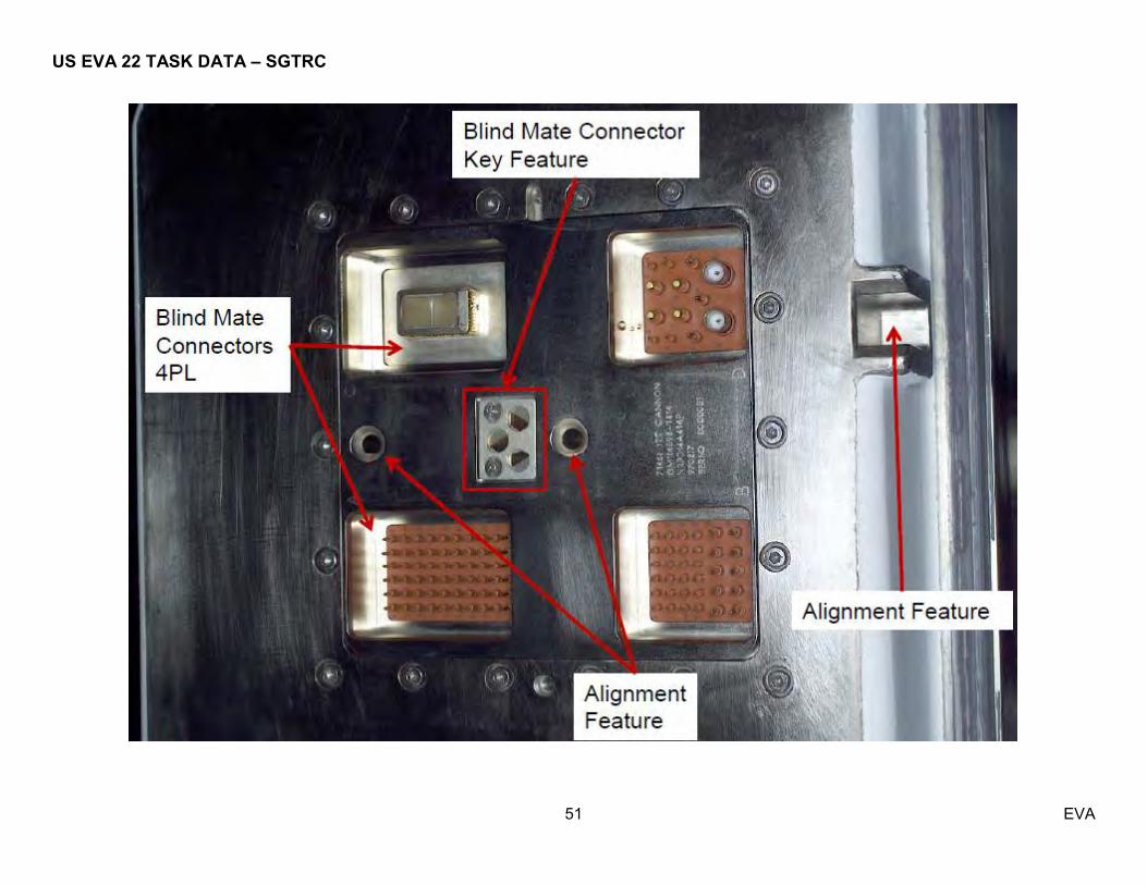
51 EVA

US EVA 22 TASK DATA – SGTRC
52 EVA
US EVA 22 TASK DATA – SGTRC
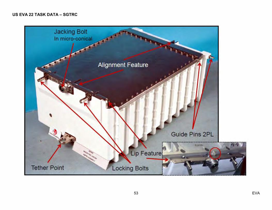
53 EVA

US EVA 22 TASK DATA – SGTRC
54 EVA

US EVA 22 TASK DATA – SGTRC
55 EVA

US EVA 22 TASK DATA – SGTRC
56 EVA
US EVA 22 TASK DATA – SGTRC
57 EVA
Z1 HR 6058 Z1 HR 6059 Z1 HR 6057

US EVA 22 TASK DATA – MISSE 8
58 EVA
Estimated Task Duration:
With RMS Without RMS One EV N/A 01:10
Tools:
EV2 28mm EVA Camera w/ Bracket
Restraints:
HR WIF APFR Setting MISSE FRAM and ELC 2 HRs as required
N/A n/A
ORUs: Item P/N Failed
s/n Spare s/n
Mass (lb) Dimensions (in)
PEC FT-TA-8010-01 N/A N/A 80.2 33.6x30.9x6.8 ORMatE Tray FT-TA-8210-01 N/A N/A 12.9 19.55x9x3.03
ORMatE Cover FT-TA-8220-01 N/A N/A 6 19.27x10.83x2.59
EVA Connectors:
Harness From To Clamps (#) Conn Size Function P1 JMU/CIB PEC 7A 1 21 PWR/DATA P2 JMU/CIB PEC 7B 1 21 PWR/DATA
EVA Fasteners:
Fastener Name
Label Head Size
Qty Install Trq (ft-lb)
Release Trq (ft-lb)
Failure Trq (ft-lb)
Turns RPM
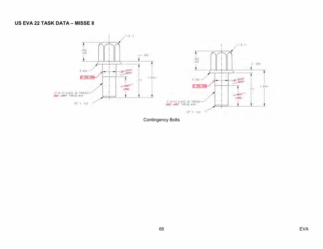
PEC Contingency Bolts
PEC 8 7/16‖ 2 10.58 ground 6.5 21.66 11.5 30
ORMatE-III R/W Contingency Bolts
ORMatE-III R/W
7/16 2 10.6-12.3 9.58 21.66 6.5 30

US EVA 22 TASK DATA – MISSE 8
59 EVA
Warning: 1. Do not touch hinged side while closing MISSE PEC – EVA Safety
Caution:
1. Avoid contact with deployed MISSE and silver avionics boxes on ExPA – DOD Note:
1. Requires 28mm EVA Camera - DOD 2. Contingency bolts designed after issues releasing MISSE 6 – DOD 3. All ELC2 HRs are good for BRT – EVA AIT 4. Avoid sideloads when installing cover over ORMatE 5. Cover is labled with RAM side Fwd 6. MISSE 8 PIP pins do not come all the way out of sockets 7. Exceptions taken: allignment features, connectors on PEC within 1.4‖ of HR, HR envelope clearances obstructed by probe and soctes, EMI 8. GP Cutters required if have to cut electrical cable (1.22-1.4‖)
Timeline Considerations: 1. No thermal clock after PEC is closed– DOD; PTCS 2. MISSE 8 PEC and ORMatE do not have to be brought IVA at the same time, however, due to IVA packing constraints, it is more efficient IVA-wise to bring them in at the same time – DOD 3. MISSE 8 PEC is higher priority than MISSE 8 ORMatE – DOD 4. MISSE 8 PEC and ORMatE can withstand induced loads from being tethered outside ISS between EVAs – DOD 5. The MISSE 8 connectors, PEC receptacles and dummies are all keyed – DOD 6. There are no washers on the non-captive contingency bolts; just the tether loop and bolt - DOD 7. MISSE 8 PEC door must be opened to release the contingency bolt - DOD

US EVA 22 TASK DATA – MISSE 8
60 EVA

US EVA 22 TASK DATA – MISSE 8
61 EVA

US EVA 22 TASK DATA – MISSE 8
62 EVA
US EVA 22 TASK DATA – MISSE 8
63 EVA

US EVA 22 TASK DATA – MISSE 8
64 EVA

US EVA 22 TASK DATA – MISSE 8
65 EVA
US EVA 22 TASK DATA – MISSE 8
66 EVA
Contingency Bolts
US EVA 22 TASK DATA – RGB
67 EVA
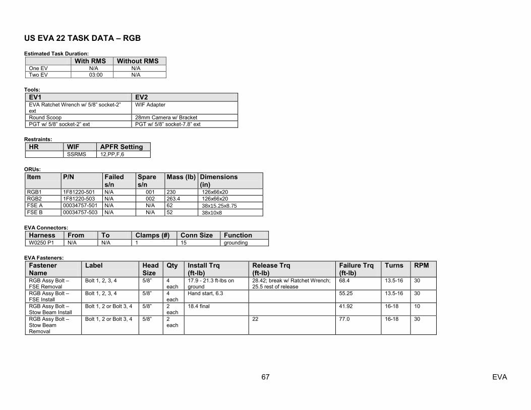
Estimated Task Duration: With RMS Without RMS One EV N/A N/A Two EV 03:00 N/A
Tools:
EV1 EV2 EVA Ratchet Wrench w/ 5/8‖ socket-2‖ ext
WIF Adapter
Round Scoop 28mm Camera w/ Bracket PGT w/ 5/8‖ socket-2‖ ext PGT w/ 5/8‖ socket-7.8‖ ext
Restraints:
HR WIF APFR Setting SSRMS 12,PP,F,6
ORUs: Item P/N Failed
s/n Spare s/n
Mass (lb) Dimensions (in)
RGB1 1F81220-501 N/A 001 230 126x66x20 RGB2 1F81220-503 N/A 002 263.4 126x66x20 FSE A 00034757-501 N/A N/A 62 38x15.25x8.75 FSE B 00034757-503 N/A N/A 52 38x10x8
EVA Connectors:
Harness From To Clamps (#) Conn Size Function W0250 P1 N/A N/A 1 15 grounding
EVA Fasteners:
Fastener Name
Label Head Size
Qty Install Trq (ft-lb)
Release Trq (ft-lb)
Failure Trq (ft-lb)
Turns RPM
RGB Assy Bolt – FSE Removal
Bolt 1, 2, 3, 4 5/8‖ 4 each
17.9 - 21.3 ft-lbs on ground
28.42; break w/ Ratchet Wrench; 25.5 rest of release
68.4 13.5-16 30
RGB Assy Bolt – FSE Install
Bolt 1, 2, 3, 4 5/8‖ 4 each
Hand start, 6.3 55.25 13.5-16 30
RGB Assy Bolt – Stow Beam Install
Bolt 1, 2 or Bolt 3, 4 5/8‖ 2 each
18.4 final 41.92 16-18 10
RGB Assy Bolt – Stow Beam Removal
Bolt 1, 2 or Bolt 3, 4 5/8‖ 2 each
22 77.0 16-18 30

US EVA 22 TASK DATA – RGB
68 EVA
Ground Install Bolt Info (ft-lbs): Bolt Initial
turns Running trq
Final turns
Final trq
1-4 10.75 7.92 15.625 19.17 1-3 15 6.67 15.385 17.92 1-2 15 8.33 15.5 19.58 1-1 15 8.33 15.5 19.58 2-4 15.25 6.67 15.5 17.92 2-3 15 10.00 15.375 21.25 2-2 15 9.17 16.25 20.42 2-1 15 10.00 15.5 21.25
Contingency EVA Fasteners:
Fastener Name
Label Head Size
Qty Install Trq
(ft-lb)
Release Trq
(ft-lb)
Failure Trq
(ft-lb)
Turns RPM
FRGF Grapple Shaft EVA Release Rod, 10 O'Clock Position
unmarked 1/2" 1 9.2 +/- 1 (PGT A7)
20 9 CCW
FRGF Grapple Shaft EVA Release Rod, 4 O'Clock Position
Black segment on Abutment Plate edge next to the drive
1/2" 1 9.2 +/- 1 (PGT A7)
To hard stop
20 8 CW
LGF Grapple Shaft EVA Release Rod, 6 O'Clock Position
unmarked 1/2" 1 9.2 +/- 1 (PGT A7)
20 9 CCW
LGF Grapple Shaft EVA Release Rod, 12 O'Clock Position
unmarked, behind grapple target
1/2" 1 9.2 +/- 1 (PGT A7)
To hard stop
20 8 CW
POA Latches Manual EVA Drive
This activity will not be required as latches will be disengaged prior to the EVA day and the RGB bundle will be secured via the POA snares – ROBO MOD
Warning:
1. Due to entrapment hazard, do not insert glove into the exposed latch mechanisms – EVA Safety 2. Curvic coupling does not meet sharp edge requirements – EVA Safety
Caution:
1. Keep loads into Radiator Beam close to centerline ref FR B18-351, B1 – S&M 2. All loads (translation, BRT) must be constrained to RGB2 (port RGB) and FSEs once all 4 bolts on RGB1 have broken trq >1.25 turns – S&M 3. Previous issue on zip nuts when installing Stow Beams. Zip nuts are very sensitive to side-loading. Reference IFI 7532 – EV&CS 4. Breaking torque more or less than 1-1.25 turns can cause biding and damage to the RGBs – S&M
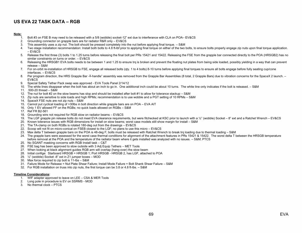
US EVA 22 TASK DATA – RGB
69 EVA
Note:
1. Bolt #3 on FSE B may need to be released with a 5/8 (wobble) socket-12‖ ext due to interferance with CLA on POA– EV&CS 2. Grounding connector on grapple bars are for radiator R&R only – EV&CS 3. This assembly uses a zip nut. The bolt should be pressed completely into the nut before applying final torque. – S&M 4. Two stage installation recommendation: Install both bolts to 4.8 ft-lbf prior to applying final torque on either of the two bolts, to ensure bolts properly engage zip nuts upon final torque application.
– EV&CS 5. Release the first three (3) bolts 1 to 1.25 turns before releasing the final bolt per PRs 15421 and 15422. Releasing the FSE from the grapple bar connected directly to the POA (HRSGB2) has no
similar constraints on turns or order. – EV&CS 6. Releasing the HRSGB1 EVA bolts needs to be between 1 and 1.25 to ensure trq is broken and prevent the floating nut plates from being side loaded, possibly yielding in a way that can prevent
release – S&M 7. For on-orbit re-installation of HRSGB to FSE, engage all released bolts (qty. 1 to 4 bolts) 8-10 turns before applying final torques to ensure all bolts engage before fully seating cup/cone
interfaces. – EV&CS 8. Per program direction, the HRS Grapple Bar ―T-handle‖ assembly was removed from the Grapple Bar Assemblies (8 total, 2 Grapple Bars) due to vibration concerns for the SpaceX 2 launch. –
EV&CS 9. Special Safety Tether Pack swap was approved - EVA Tools Panel 2/14/12 10. The white lines disappear when the bolt has about an inch to go in. One additional inch could be about 10 turns. The white line only indicates if the bolt is released. – S&M 11. .500-20 thread – S&M 12. The nut for bolt #2 on the stow beams has slop and should be installed after bolt #1 to allow for tolerance stackup – S&M 13. Zip nuts are sensitive to side loads and high RPMs; recommendation is to use wobble and a PGT setting of 10 RPMs – S&M 14. SpaceX FSE nuts are not zip nuts – S&M 15. Cannot put cyclical loading of >30lbs in bolt direction while grapple bars are on POA – EVA AIT 16. Only 1 EV allowed FF on the RGBs; no quick loads allowed on RGBs – S&M 17. Ref FR B2-561 18. Grounding wire not required for RGB stow on radiator beams – EV&CS 19. The LGF grapple pin release bolts do not meet EVA clearance requirements, but were fitchecked at KSC prior to launch with a ½‖ (wobble) Socket – 8‖ ext and a Ratchet Wrench – EV&CS 20. Known tolerance issues with RGB dimensions for install on stow beams; worst case models still show margin for install – S&M 21. The TA-clamp on both RGBs is rotated 180-deg out from the drawings – EV&CS 22. Scoop will not fit on micro-conical on FSEB closest to the LGF; no plans to use this micro – EV&CS 23. Max delta T between grapple bars on the POA is 48-deg F; bolts must be released with Ratchet Wrench to break trq loading due to thermal loading – S&M 24. The grapple bars were assessed for the worst case thermal conditions for alignment of the attachment features in PRs 15421 & 15422. The worst delta T between the HRSGB temperature
before removal at the POA and the temperature of the radiator beam where it gets installed was analyzed with no issues. – S&M; PTCS 25. No SGANT masking concerns with RGB Install task – C&T 26. FSE bag has been approved to stow outside with 3 Adj Equip Tethers – MET Tools 27. When looking at black alignment guides RGB arm will overlap (hang-over) the stow beam 28. Initial confige: Starboard HRSGB = HRSGB 1; Port HRSGB - HRSGB 2, has LGF, attached to POA 29. ½‖ (wobble) Socket -8‖ ext in Z1 jumper boxes – MOD 30. Max force required to zip bolt is 11-lbs – S&M 31. Failure Mode for Release = Nut Plate Shear Failure; Install Mode Failure = Bolt Shank Shear Failure – S&M 32. For RGB installation on truss into zip nuts, the first torque can be 3.8 or 4.8 ft-lbs. – S&M
Timeline Considerations: 1. WIF adapter approved to leave on LEE – CSA & MER Tools 2. Long pole in procedure is EV on SSRMS - MOD 3. No thermal clock – PTCS
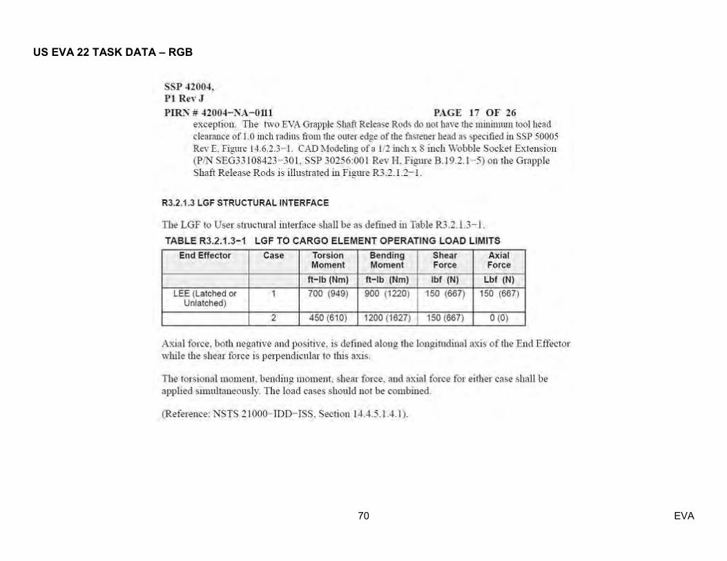
US EVA 22 TASK DATA – RGB
70 EVA
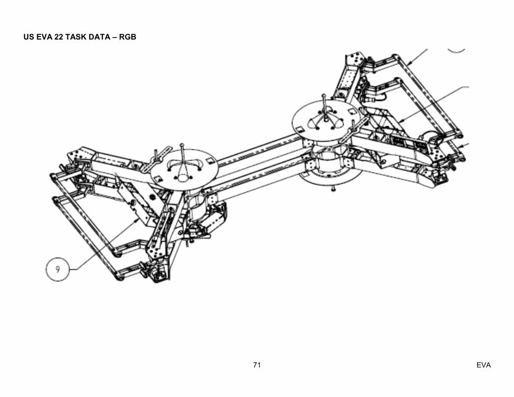
US EVA 22 TASK DATA – RGB
71 EVA
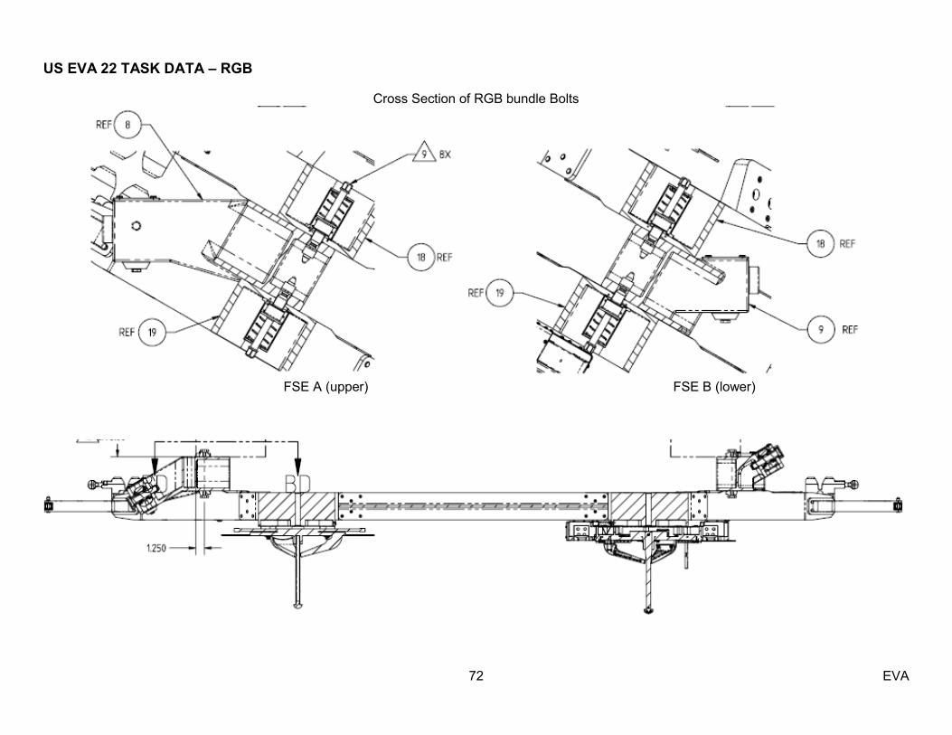
US EVA 22 TASK DATA – RGB
72 EVA
Cross Section of RGB bundle Bolts
FSE A (upper) FSE B (lower)

US EVA 22 TASK DATA – RGB
73 EVA

US EVA 22 TASK DATA – RGB
74 EVA
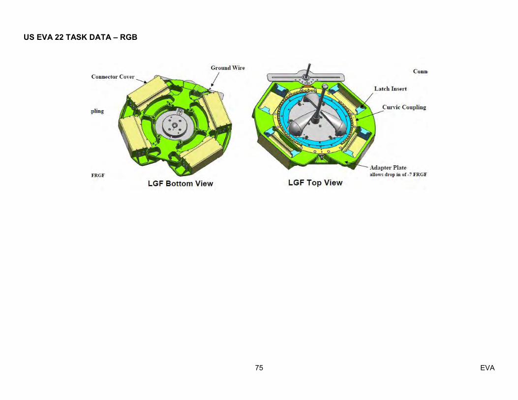
US EVA 22 TASK DATA – RGB
75 EVA
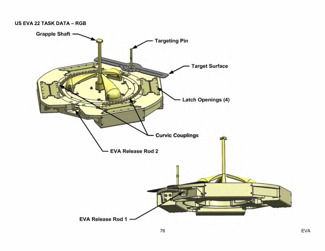
US EVA 22 TASK DATA – RGB
76 EVA
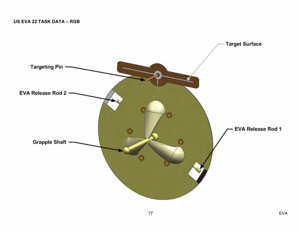
US EVA 22 TASK DATA – RGB
77 EVA
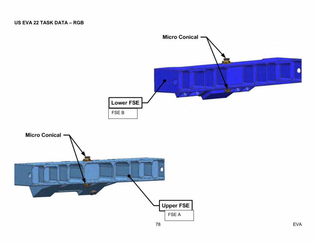
US EVA 22 TASK DATA – RGB
78 EVA
FSE B
FSE A
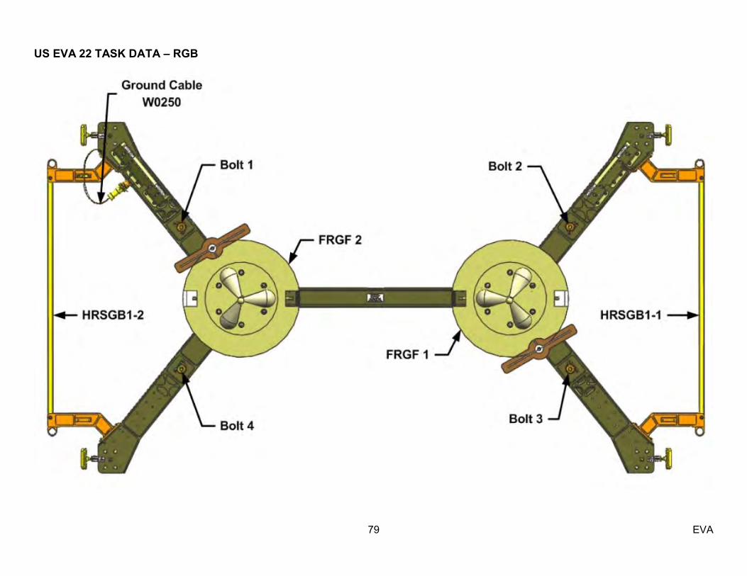
US EVA 22 TASK DATA – RGB
79 EVA

US EVA 22 TASK DATA – RGB
80 EVA

US EVA 22 TASK DATA – RGB
81 EVA
FSE A
FSE B
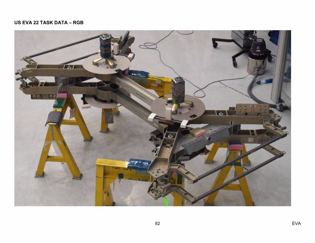
US EVA 22 TASK DATA – RGB
82 EVA

US EVA 22 TASK DATA – RGB
83 EVA
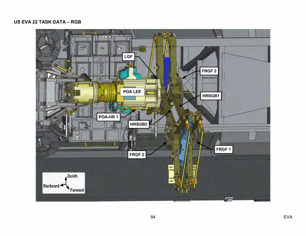
US EVA 22 TASK DATA – RGB
84 EVA

US EVA 22 TASK DATA – RGB
85 EVA
Port RGB Bolt #3 access with 12‖ wobble socket
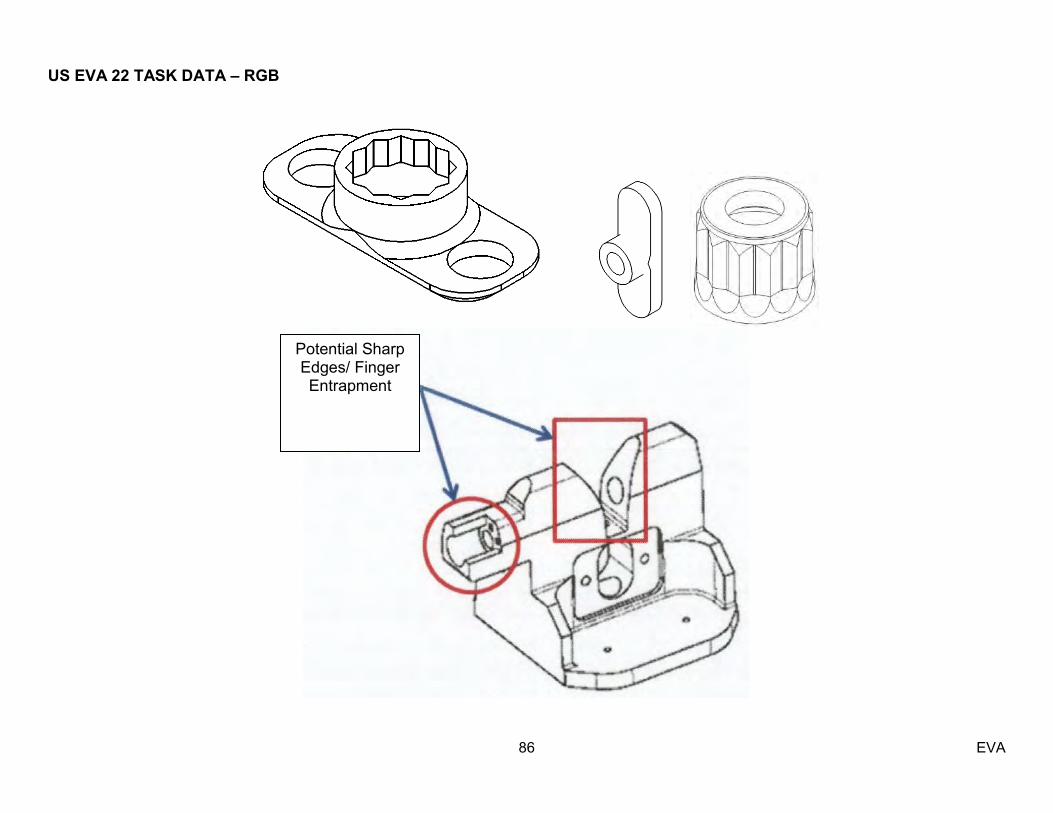
US EVA 22 TASK DATA – RGB
86 EVA
Potential Sharp Edges/ Finger Entrapment

US EVA 22 TASK DATA – RGB
87 EVA
Inboard Bolt and Stow Beam receptacle (zip nut)

US EVA 22 TASK DATA – RGB
88 EVA
Outboard Bolt and Stow Beam receptacle (zip nut)

US EVA 22 TASK DATA – RGB
89 EVA
V-Guide EVA Bolt – Drawing shows white lines will be in deep when engaged

US EVA 22 TASK DATA – RGB
90 EVA
(.925)
US EVA 22 TASK DATA – MLM POWER CABLE
91 EVA
Estimated Task Duration: With RMS Without RMS One EV N/A 00:30
Tools:
EV1 N/A
Restraints:
HR WIF APFR Setting N/A n/A
EVA Connectors:
Harness From To Clamps (#) Conn Size Function Mass (lbs) W5634 J2 Fwd/Zenith
A/L PMA1 N/A 25 Power 22.48
Warning:
1. Caution:
1. Avoid inadvertant contact with zenith PMA1 MDM radiator, above 22‖ of OTD (US crane), and SASA high and low gain Antennas and radiator surfaces Note:
1. It is important to prevent routing the cable over Safety Tethers and Gaps Spanners 2. No IFIs for this Hardware – EV&CS 3. Per S. Williams and WVS, cable was left on aft side of the fwd/zenith A/L HPGT
Timeline Considerations: 1. This task can be broken out at any point

US EVA 22 TASK DATA – MLM POWER CABLE
92 EVA

US EVA 22 TASK DATA – MLM POWER CABLE
93 EVA

US EVA 22 TASK DATA – MLM POWER CABLE
94 EVA
EV Path
MLM Power Cable Path

US EVA 22 TASK DATA – CLPA
95 EVA
Estimated Task Duration: With RMS Without RMS One EV 00:40 01:30 Two EV 00:30 01:30
Tools:
EV1 EV2 Square Scoops Square Scoops PGT w/7/16‖ socket 6‖ extension
Restraints:
HR WIF APFR Setting MBS Mast CLPA Retrieval
SSRMS 12, PP, F, 6 MBS WIF 7
3, NN, K, 9
ORUs: Item P/N Failed
s/n Spare s/n
Mass (lb) Dimensions (in)
CLPA (Mast) 51612-3004-1 203 N/A 46.11 22.47x17x16.82 EVA Fasteners:
Fastener Name
Label Head Size
Qty Install Trq (ft-lb)
Release Trq (ft-lb)
Failure Trq (ft-lb)
Turns RPM
CLPA Tie-Down Bolt
None 7/16‖ 1 10.8-16.7 25.5 43.0 24-26 = hard stop 19 = fully released
30
US EVA 22 TASK DATA – CLPA
96 EVA
Warning: 1. Avoid handling grounding points, connectors, and bolt threads when ORU is released. Failure to comply may result in crew injury or equipment damage. – CSA 2. After the CLPA is removed from the MBS Mast, the receptacle connectors will be left exposed. A 2 ft KOZ from these connectors will apply if the respective VDU are no inhibited. Ref MSS-
SNCR-046 – Safety Caution:
1. Avoid handling the front surfaces of the lens/lighting assembly. Failure to comply may result in equipment damage – CSA 2. Do not use a prybar to aid in removal of the CLPA as the connector box wedge can be damaged
Note:
1. Bolt is not free spinning. Drive to turn count, not hard stops - CSA 3. GTEC may be used to cover passive blind-mate connector on MBS mast – CSA; EVA AIT 4. No thrusters while EV on SSRMS and within 2 ft structure – CSA 5. When releasing the CLPA: mechanical safing is lost after 5 turns, bolt is no longer threaded in nut after 14 turns, bolt threads are not exposed after 19 turns – CSA
Timeline Considerations:
1. There is no thermal clock for this hardware – CSA; PTCS
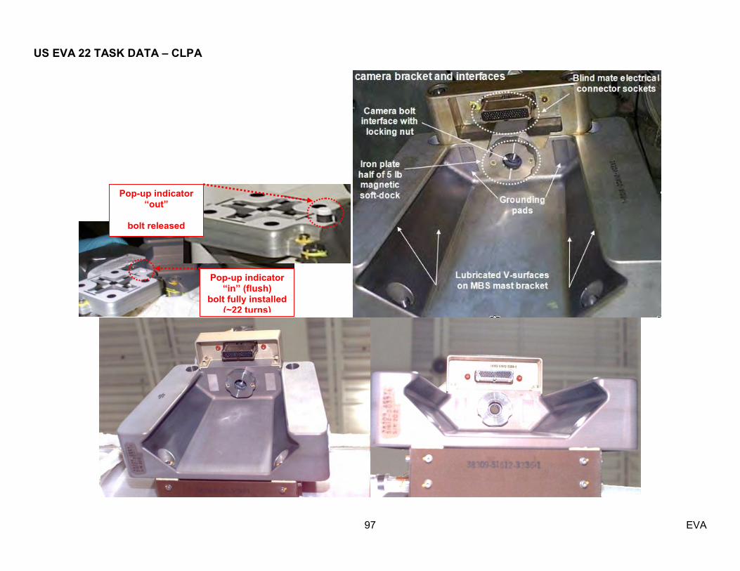
US EVA 22 TASK DATA – CLPA
97 EVA
Pop-up indicator “in” (flush)
bolt fully installed (~22 turns)
Pop-up indicator “out”
bolt released
more than 5 turns

US EVA 22 TASK DATA – CLPA
98 EVA

US EVA 22 TASK DATA – CLPA
99 EVA
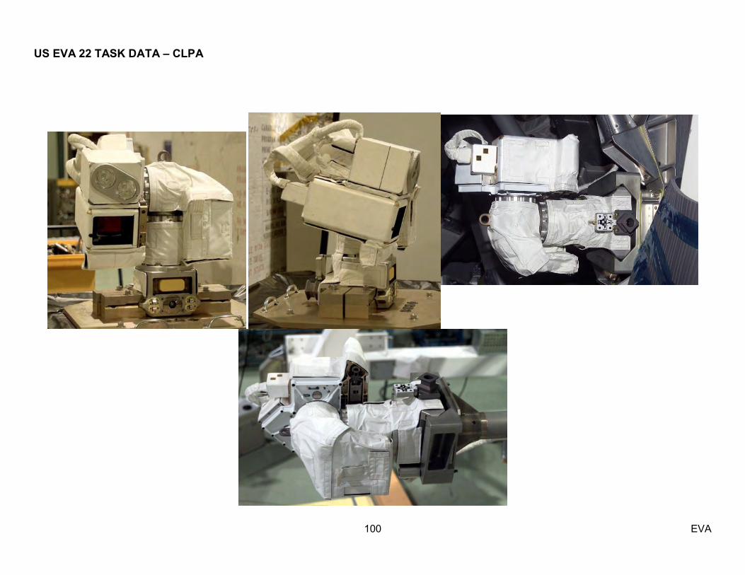
US EVA 22 TASK DATA – CLPA
100 EVA

US EVA 22 TASK DATA – CLPA
101 EVA

US EVA 22 TASK DATA – CLPA
102 EVA
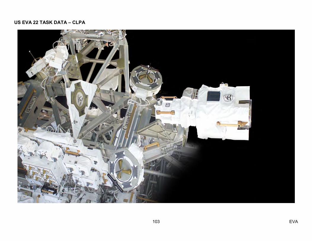
US EVA 22 TASK DATA – CLPA
103 EVA

US EVA 22 TASK DATA – CLPA
104 EVA
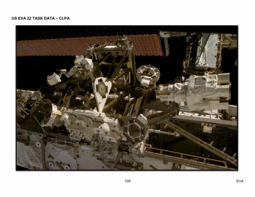
US EVA 22 TASK DATA – CLPA
105 EVA
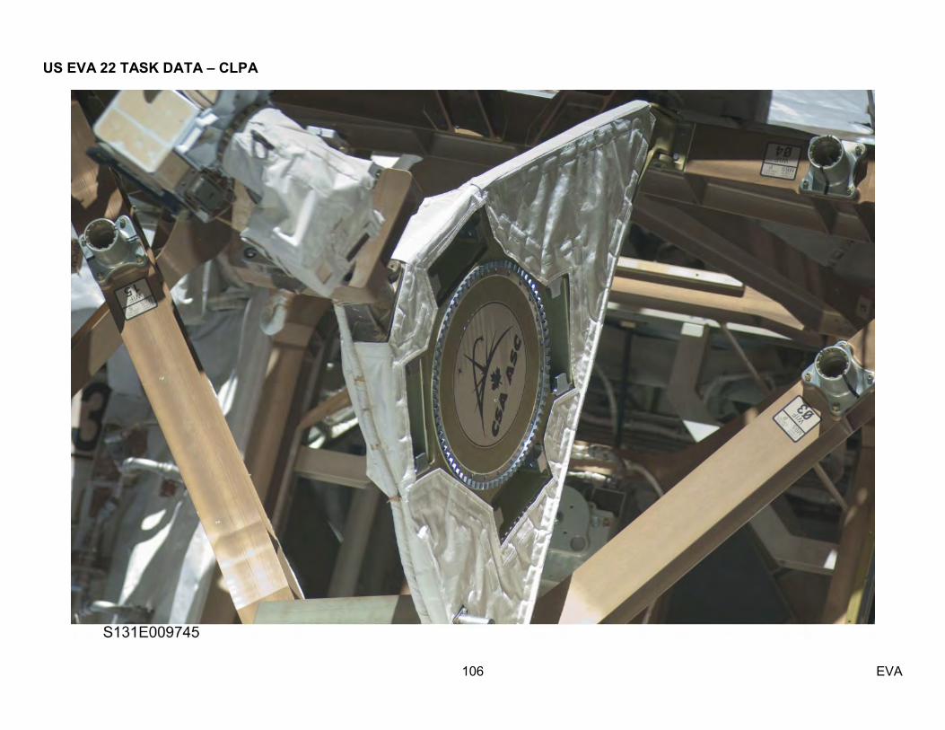
US EVA 22 TASK DATA – CLPA
106 EVA
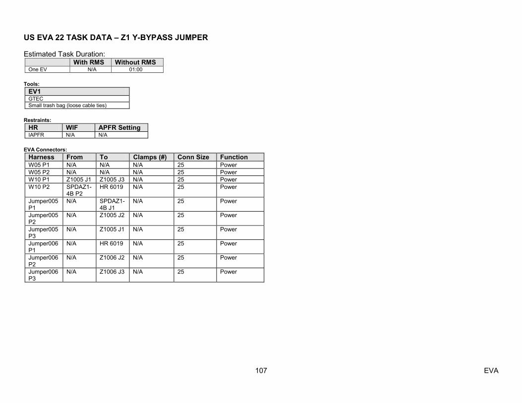
US EVA 22 TASK DATA – Z1 Y-BYPASS JUMPER
107 EVA
Estimated Task Duration: With RMS Without RMS One EV N/A 01:00
Tools:
EV1 GTEC Small trash bag (loose cable ties)
Restraints:
HR WIF APFR Setting IAPFR N/A N/A
EVA Connectors:
Harness From To Clamps (#) Conn Size Function W05 P1 N/A N/A N/A 25 Power W05 P2 N/A N/A N/A 25 Power W10 P1 Z1005 J1 Z1005 J3 N/A 25 Power W10 P2 SPDAZ1-
4B P2 HR 6019 N/A 25 Power
Jumper005 P1
N/A SPDAZ1-4B J1
N/A 25 Power
Jumper005 P2
N/A Z1005 J2 N/A 25 Power
Jumper005 P3
N/A Z1005 J1 N/A 25 Power
Jumper006 P1
N/A HR 6019 N/A 25 Power
Jumper006 P2
N/A Z1006 J2 N/A 25 Power
Jumper006 P3
N/A Z1006 J3 N/A 25 Power
US EVA 22 TASK DATA – Z1 Y-BYPASS JUMPER
108 EVA
Warning: 1. Do not demate Cable W05 Connectors P1 or P2 as these connections are not inhibitied
Caution:
1. Avoid contact with PCU cathode and HCA ports (Z1) Note:
1. Prior to Z1 Y-Bypass Jumper (R081661-1) installation, the N1 Isolation Cable (W5210-1) must be installed to prevent power back-flow to Z1 (OCAD)—completed 2. Task inhibits take down several other pieces of ISS hardware: FGB ARCU 53, SGANT 2, PCU 2, CMG 4 3. FPP booties may be required to cover unmated connectors due to touch temperature constraints – per EV&CS 4. Sockets are always on the powered side here. The patch panels have sockets and the P3 and P2 connectors on the Y side of the Jumper have pins, while the P1 side of the Jumper has sockets
with the J1 connector on the SPDA having pins. - EPS 5. The Y side connectors of the jumper are interchangeable with each other. It does not matter if J3 or J2 gets connected to P1 or P2. But the jumpers are NOT interchangeable with each other. -
EPS 6. All the caps that fit on one plug (P side on the cables) will fit on all the Ps. Same with the jacks (J sides). – EPS 7. Z1 Patch Panel Z1-006 caused label J3 is missing– EV&CS 8. Due to potential for high temperatures on the Z1 unmated connectors, the connectors must be insulated by at least 3 layers of the bootie material, requiring 2 booties 9. Z1 Aux Bag, flap opens zenith 10. J3 on the patch panels are un-powered receptacles – EV&CS 11. Due to an orbiter loads issue red plastice cable ties (similar to those used to secure cables on electronic equipment in cars) were added to several Z1 harnesses. The cable ties are not required
for on orbit operations and they can be removed if they are still present (very suseptable to AO). The will likely break if the cable is moved much. – EV&CS 12. W10 has a p-clamp near the diagonal handrail. W05 has a p-clamp after the TA-clamp coming from the P2 end. – EV&CS 13. Missing label on zenith X2 J3 Patch Panel jack 14. Wire Tie and GTEC config has been approved – MER Tools and EV&CS 15. No IFIs on this hardware – EV&CS
Timeline Considerations:
1. System can be re-powered if all three legs of the jumper are properly installed or capped. The jumper cannot be re-energized with an uncapped leg. Capping is also required within 90days to prevent degredation of the materials inside the connector. – EPS
US EVA 22 TASK DATA – Z1 Y-BYPASS JUMPER
109 EVA
Packing Procedures of Z1 Jumpers:
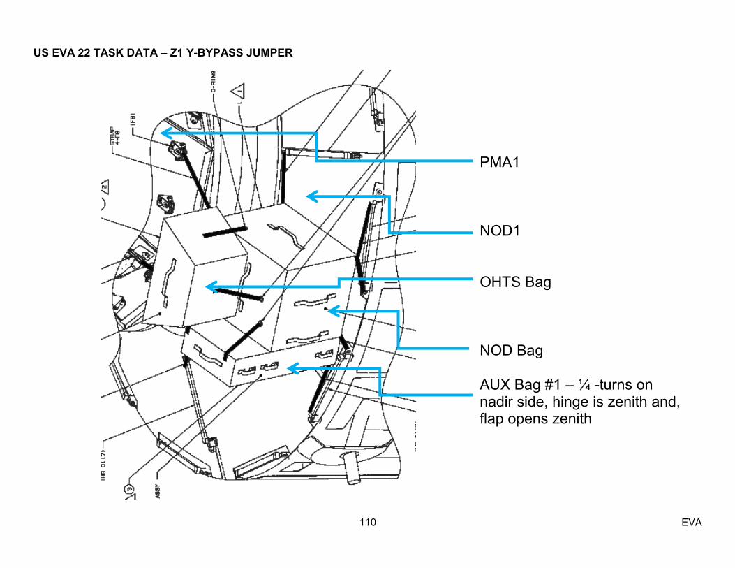
US EVA 22 TASK DATA – Z1 Y-BYPASS JUMPER
110 EVA
PMA1 NOD1 OHTS Bag NOD Bag AUX Bag #1 – ¼ -turns on nadir side, hinge is zenith and, flap opens zenith

US EVA 22 TASK DATA – Z1 Y-BYPASS JUMPER
111 EVA
AUX Bag #1 config
3 tether points single Velcro strap 1 pouch for each jumper per jumper restraining jumper
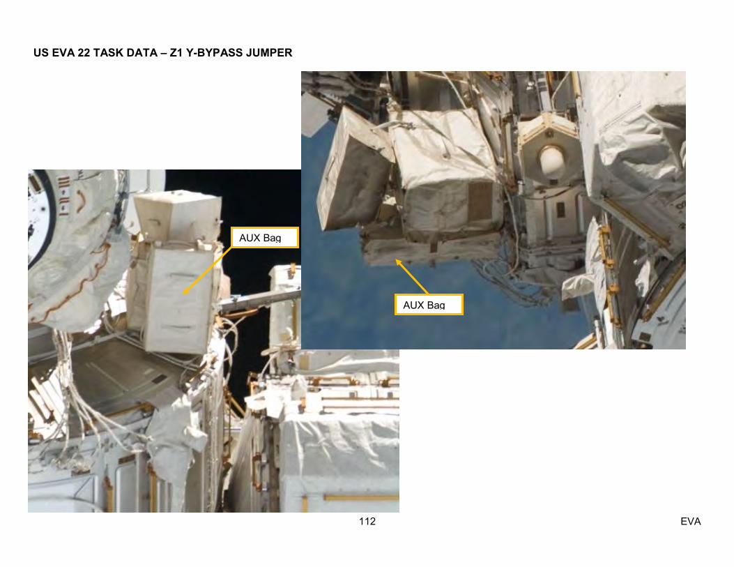
US EVA 22 TASK DATA – Z1 Y-BYPASS JUMPER
112 EVA
AUX Bag
AUX Bag

US EVA 22 TASK DATA – Z1 Y-BYPASS JUMPER
113 EVA

US EVA 22 TASK DATA – Z1 Y-BYPASS JUMPER
114 EVA

US EVA 22 TASK DATA – Z1 Y-BYPASS JUMPER
115 EVA

US EVA 22 TASK DATA – Z1 Y-BYPASS JUMPER
116 EVA

US EVA 22 TASK DATA – Z1 Y-BYPASS JUMPER
117 EVA
O-Ring shown inside receptacle around sockets. This is a contamination protection O-ring and similar O-rings have liberated on previous assembly missions.

US EVA 22 TASK DATA – Z1 Y-BYPASS JUMPER
118 EVA

US EVA 22 TASK DATA – Z1 Y-BYPASS JUMPER
119 EVA

US EVA 22 TASK DATA – Z1 Y-BYPASS JUMPER
120 EVA

US EVA 22 TASK DATA – Z1 Y-BYPASS JUMPER
121 EVA

US EVA 22 TASK DATA – Z1 Y-BYPASS JUMPER
122 EVA
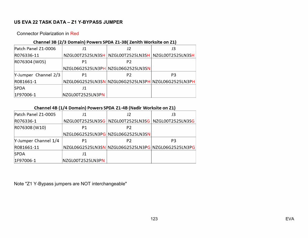
US EVA 22 TASK DATA – Z1 Y-BYPASS JUMPER
123 EVA
Note "Z1 Y-Bypass jumpers are NOT interchangeable"
Connector Polarization in Red
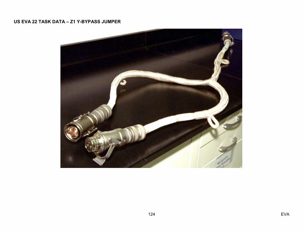
US EVA 22 TASK DATA – Z1 Y-BYPASS JUMPER
124 EVA

US EVA 22 TASK DATA – Z1 Y-BYPASS JUMPER
125 EVA
Tether Hook
Tether Points
Cinch Straps (2)

US EVA 22 TASK DATA – PMA 2 COVER INSTALL
126 EVA
Estimated Task Duration: With RMS Without RMS One EV N/A 00:60 Two EV N/A 00:35
Tools:
EV1 EV2 N/A NOD 3 Avionics Bag
Restraints:
HR WIF APFR Setting N/A N/A N/A
ORUs: Item P/N Failed
s/n Spare s/n
Mass (lb) Dimensions (in)
PMA 2 Cover 684-022327-0001
N/A 001 38lbs 20x24x10 inches folded
Warning:
1. Stay clear of PMA fwd mating surface due to potential sharp edge with latching mechanisms – EVA Safety 2. Sharp edge potential with PMA umbilical launch restraints - exposed bolt threads – EVA Safety
Caution:
1. Avoid inadvertent contact with TCS reflector (PMA 2) – EVA Safety 2. There must be at least a ½‖ overlap between the PMA 2 Cover and the fwd face mating surface - PTCS
Note:
1. Diameter of cover was increased 2‖ and straps were increased 2‖ each, 4 soft good EVA handles were added in addition to the 4 EVA tether points, due to lessons learned from PMA 3 cover. – EV&CS
2. A larger size bag was chosen to transport the Cover due to its increased size and its stiffness (delta from PMA 3 cover) – MOD 3. The cover can be folded and unfolded an unlimited number of times without damaging the thermal properties of the cover – A&OSP 4. PMA 2 Cover does not have folding restrictions due to the material used for the MLI; it can be folded multiple times, over-and-over – EV&CS
Timeline Considerations:
1. Task can be completed by 1 or 2 EV, but 2 are preferred based on Lessons Learned from PMA 3 cover - MOD 2. Real-time analysis to be completed for any intermittent state. – PTCS

US EVA 22 TASK DATA – PMA 2 COVER INSTALL
127 EVA
NOTE With the slightly larger PMA2 Cover than the PMA3 Cover, and using the larger NOD Avionics Bag, the PMA2 Cover might have to be folded in more
times in the accordian fashion shown. There are no constraints on the number of folds. What is important is that the Cut Out and Label end up as shown. The cutout and label go in facing the bottom of the bag, so that they can flip over when removing the cover.
Recommendation to fold the cover 5 times rather than 3 to fit into the skinnier/ longer NOD3 Avionics Bag.
0417
041604180415
0414
0413
0412 0411
0410

US EVA 22 TASK DATA – PMA 2 COVER INSTALL
128 EVA
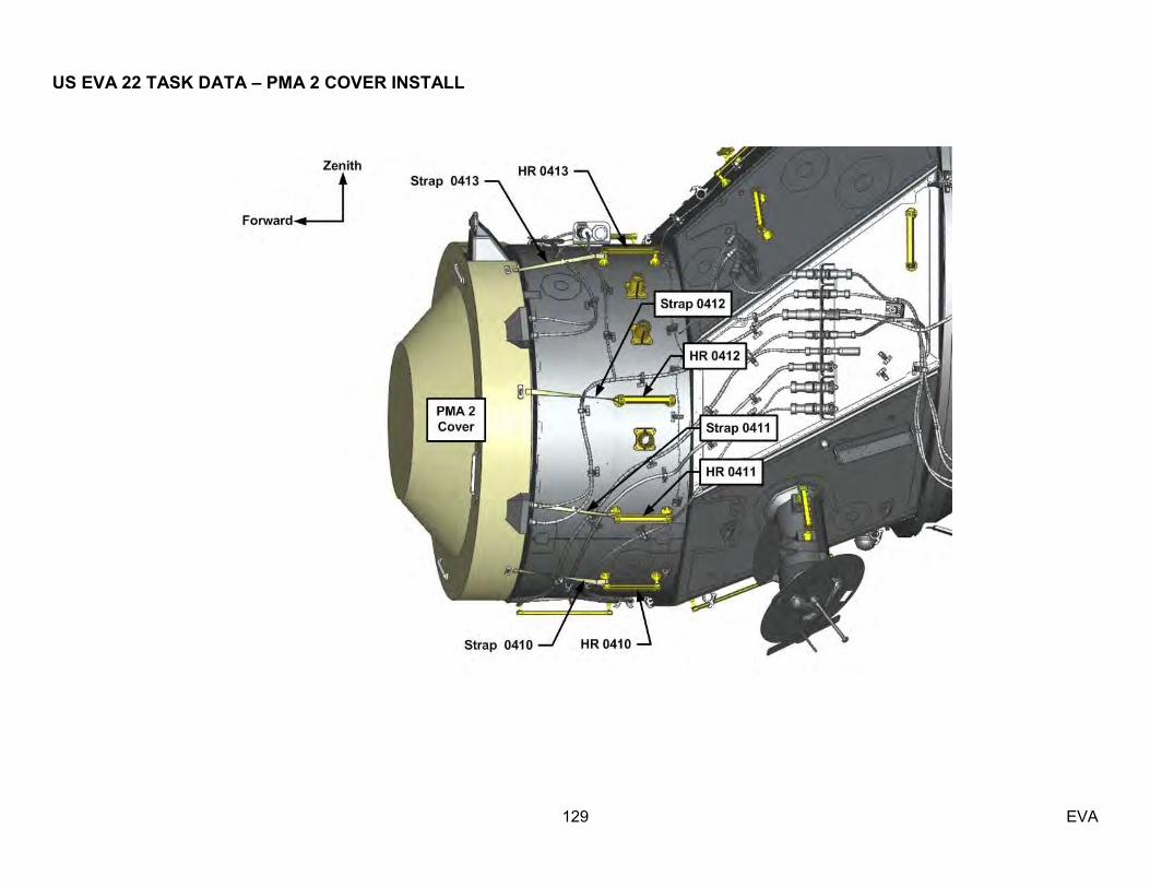
US EVA 22 TASK DATA – PMA 2 COVER INSTALL
129 EVA

US EVA 22 TASK DATA – PMA 2 COVER INSTALL
130 EVA
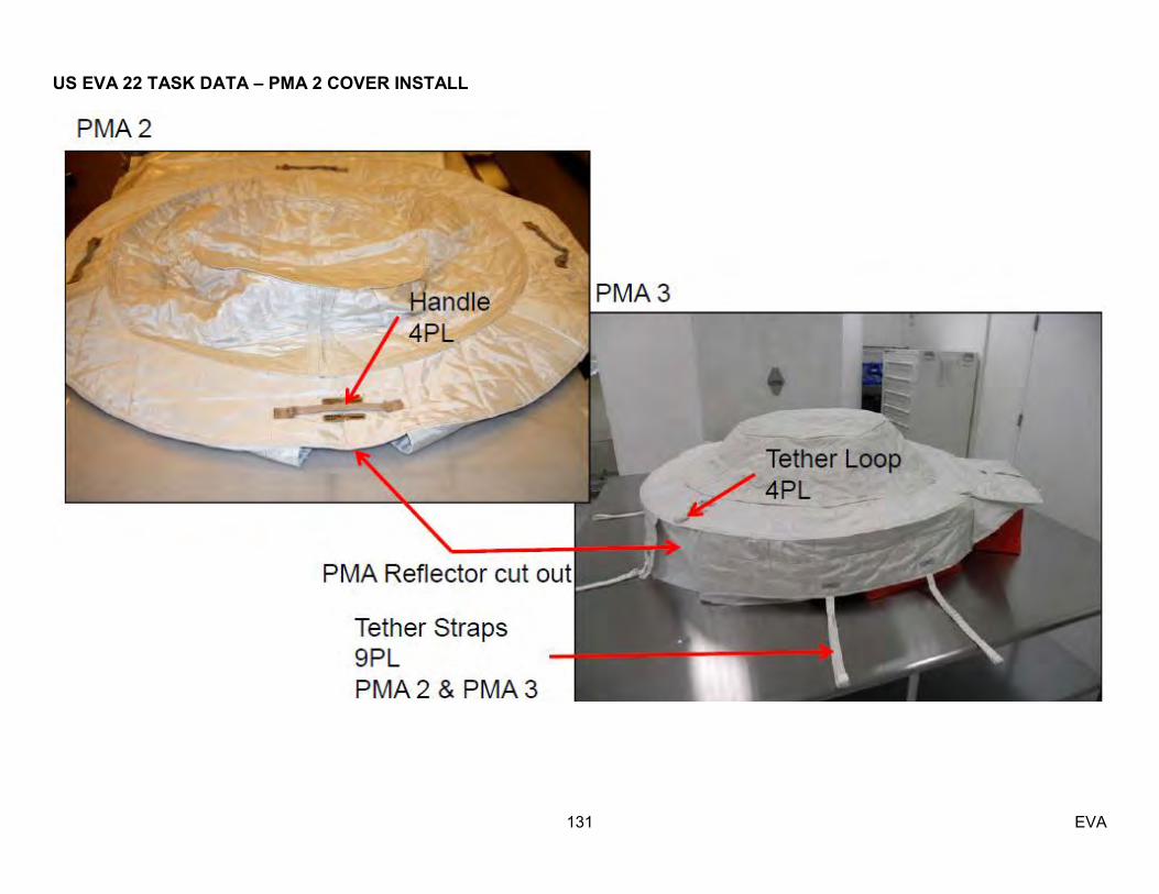
US EVA 22 TASK DATA – PMA 2 COVER INSTALL
131 EVA
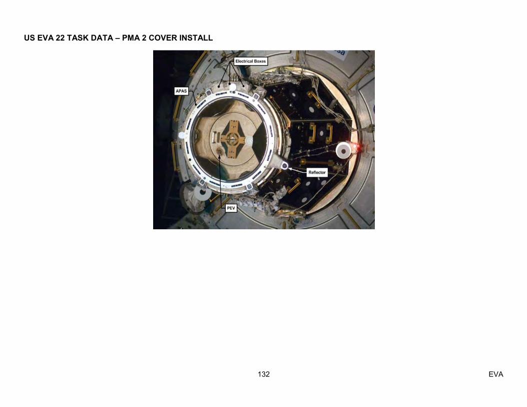
US EVA 22 TASK DATA – PMA 2 COVER INSTALL
132 EVA
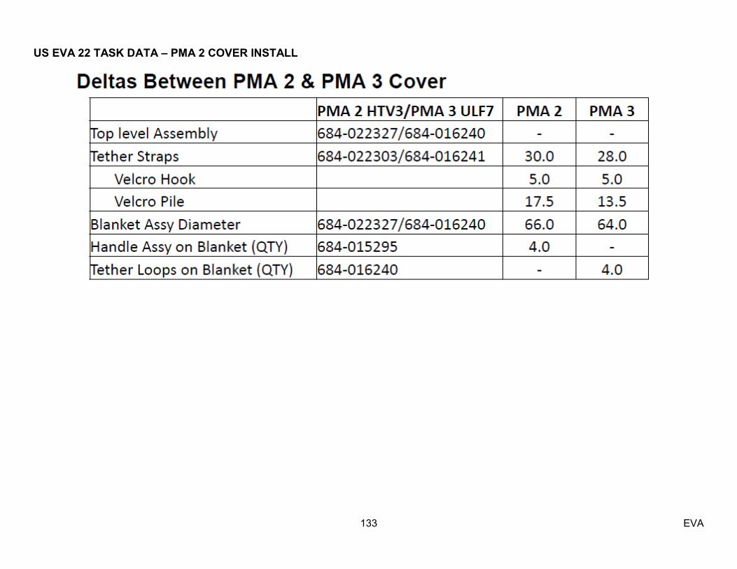
US EVA 22 TASK DATA – PMA 2 COVER INSTALL
133 EVA

134 EVA
Estimated Task Duration: With RMS Without RMS
One EV Crew n/a 0:45 Two EV Crew n/a n/a
Tools:
EV1 EV2 Ethernet cable Wire ties Fishstringer Tethers
EVA Connectors:
Connector To Size Function P2 J2 21 Ethernet
J578 TBD RSOS TBD
Ethernet
Notes:
1. The cable length is not per drawing due to the preintegration of the wire ties. Once the final length is Known post RS connector integration it will be updated In the task data. 2. US caps were added prior to shipment to Russia. VITT cannot confirm that the caps were sharp edge Inspected at this time (Nov 2012). 3. Do not release wire tie Labeled ‗PigTail‘ 4. NZGL Cap on P2 can be removed IVA
Timeline Considerations:
1. EVA Inspection of Node 1 HR 141 is required to verify J2 connector location (nadir or zenith stanchion)
Ground photo of cable post RS connector integration.
RS bootie for RS connector
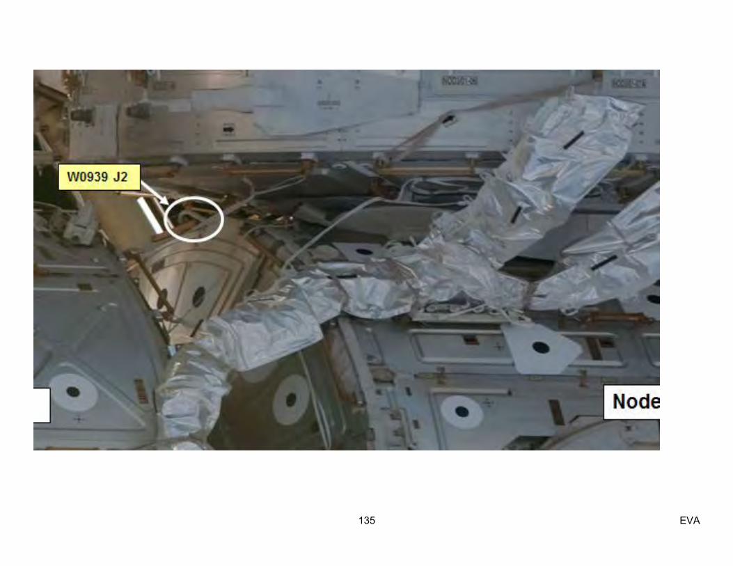
135 EVA

136 EVA

137 EVA
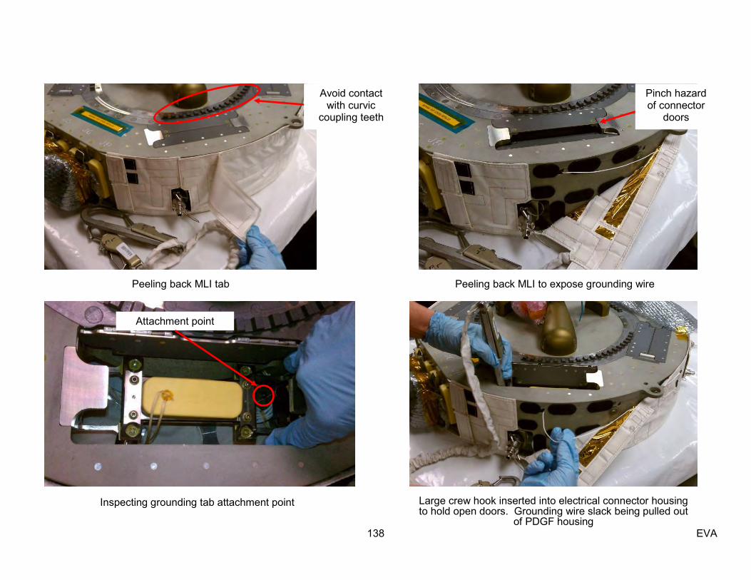
138 EVA
Peeling back MLI tab Peeling back MLI to expose grounding wire
Inspecting grounding tab attachment point
Attachment point
Avoid contact with curvic
coupling teeth
Pinch hazard of connector
doors
Large crew hook inserted into electrical connector housing to hold open doors. Grounding wire slack being pulled out
of PDGF housing

139 EVA
Grounding wire slack being stowed so that Velcro will hold it in place when MLI closed Closing MLI
Pins in electrical connector Closing MLI tab
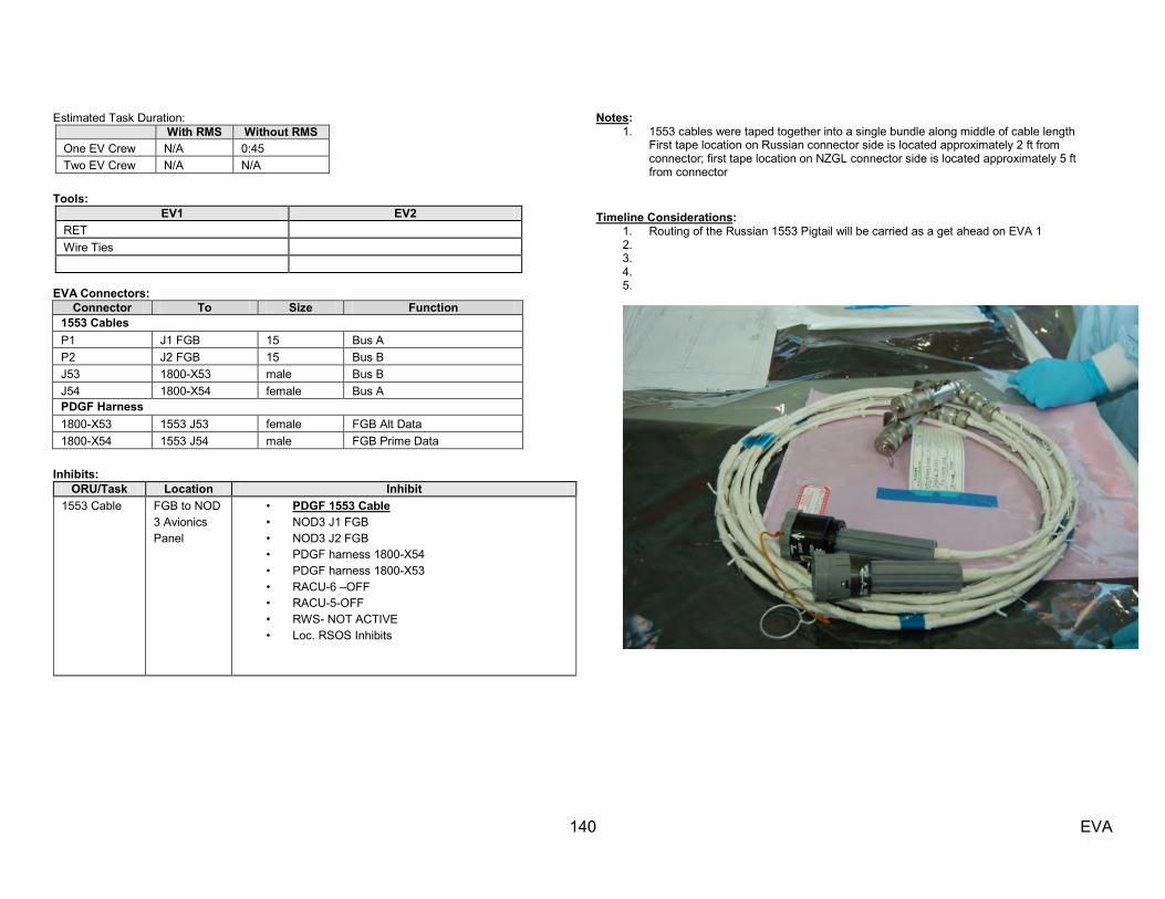
140 EVA
Estimated Task Duration: With RMS Without RMS
One EV Crew N/A 0:45 Two EV Crew N/A N/A
Tools:
EV1 EV2 RET Wire Ties
EVA Connectors:
Connector To Size Function 1553 Cables P1 J1 FGB 15 Bus A P2 J2 FGB 15 Bus B J53 1800-X53 male Bus B J54 1800-X54 female Bus A PDGF Harness 1800-X53 1553 J53 female FGB Alt Data 1800-X54 1553 J54 male FGB Prime Data
Inhibits:
ORU/Task Location Inhibit 1553 Cable FGB to NOD
3 Avionics Panel
• PDGF 1553 Cable • NOD3 J1 FGB • NOD3 J2 FGB • PDGF harness 1800-X54 • PDGF harness 1800-X53 • RACU-6 –OFF • RACU-5-OFF • RWS- NOT ACTIVE • Loc. RSOS Inhibits
Notes: 1. 1553 cables were taped together into a single bundle along middle of cable length
First tape location on Russian connector side is located approximately 2 ft from connector; first tape location on NZGL connector side is located approximately 5 ft from connector
Timeline Considerations:
1. Routing of the Russian 1553 Pigtail will be carried as a get ahead on EVA 1 2. 3. 4. 5.
141 EVA

142 EVA
PDGF
1
3 2
P7P5
P6
P8
VSC – P2
FGB J19
FGB J18
VSC - P3
VSC - P4
1553 - X54
1553 - X53
PDGF
1
3 2
P7P5
P6
P8
VSC – P2
FGB J19
FGB J18
VSC - P3
VSC - P4
1553 - X54
1553 - X53
Expected Config of Russian 1553 Jumper (wire tied to Nadir tether point on FGB PDGF)
Expected on orbit Configuration of 1553 Cable
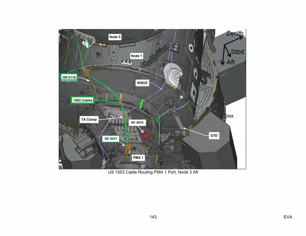
143 EVA
US 1553 Cable Routing PMA 1 Port, Node 3 Aft

144 EVA
This Page Intentionally Blank