us 20090059460
DESCRIPTION
PatentTRANSCRIPT

US 20090059460A1
United States (19)
(12) Patent Application Publication (10) Pub. N0.: US 2009/0059460 A1 Bitar (43) Pub. Date: Mar. 5, 2009
(54) TUNABLE AND AIMABLE ARTIFICIAL Publication Classi?cation LIGHTENING PRODUCING DEVICE (51) Int. Cl.
H01T 23/00 (2006.01) (76) Inventor: Peter V. Bitar, Anderson, IN (U S) F 413 15/04 (2006.01)
F41H 13/00 (2006.01) Correspondence Address: (52) US. Cl. ........................................ .. 361/232; 89/1.11
WOODARD, EMHARDT, MORIARTY, (57) ABSTRACT MCNETT & HENRY LLP . . . . . . . A tunable and a1mable arti?clal l1ghtn1ng producing device 111 MONUMENT CIRCLE’ SUITE 3700 for tetaniZing human voluntary muscle, disabling vehicular INDIANAPOLIS, IN 46204-5137 (Us) electronic ignition systems, and for pre-detonating Wired
explosives. A spark gap shaping apparatus controls a spark 21 A 1_ N _, 12/173 522 generated by a Tesla coil. A ?rst stage directionaliZer Warps a
( ) pp 0 ’ normally spherical plasma ?eld from the Tesla coil into an _ oval plasma ?eld for con?ning the spark to Within that shape.
(22) Flledi JUL 15, 2008 A second stage directionaliZer converges multiple beams to successive points just ahead of a plasma ?eld created by the
Related US Application Data ?rst stage directionalizer Without ioniZing the beams, thereby mamtammg 1omZat1on of a path of the spark. The spark 1s
(63) Continuation of application No. 11/171,775, ?led on progressively arced to these points, thereby maintaining the Jun. 30, 2005, noW Pat. No. 7,400,487.
20-\
path of the spark.

Patent Application Publication Mar. 5, 2009 Sheet 1 0f 4 US 2009/0059460 A1
20 1 SPARK \
3,4 ', GAP SHAPING
\ APPARATUS /
\J 3 CD N
POWER SUPPLY
+ 24
Patent Application Publication Mar. 5, 2009 Sheet 2 0f 4 US 2009/0059460 A1
22 FIG. 3 l GAP NOT
ENERGY gCONDUCTINGL/vj GAP ' GAP ' .0 c 6
°0 IONIZED IONIZED i i t

Patent Application Publication Mar. 5, 2009 Sheet 3 0f 4 US 2009/0059460 A1

Patent Application Publication Mar. 5, 2009 Sheet 4 0f 4 US 2009/0059460 A1
468 470
462 i 46‘? 467 El/ 472
464

US 2009/0059460 A1
TUNABLE AND AIMABLE ARTIFICIAL LIGHTENING PRODUCING DEVICE
BACKGROUND OF THE INVENTION
[0001] 1. Field of the Invention [0002] The present invention relates to a lightening produc ing device, and more particularly, the present invention relates to a tunable and aimable arti?cial lightening produc ing device. [0003] 2. Description of the PriorArt [0004] Numerous innovations for signal generating devices have been provided in the prior art that Will be described. Even though these innovations may be suitable for the spe ci?c individual purposes to Which they address, hoWever, they differ from the present invention in that they do not teach a tunable and aimable arti?cial lightening producing device. [0005] A FIRST EXAMPLE, US. Pat. No. 4,148,321 to Wyss et al. teaches an apparatus and method for the treatment and active massage of muscles, the apparatus comprising a generator arrangement providing a modulated alternating current With a medium-frequency carrier having a frequency comprised betWeen 3000 HZ and 100,000 HZ, and an adjust able loW modulating frequency of a fraction of 1 HZ, prefer ably both the carrier and the modulating currents being sinu soidal. Directly or after optional conversion to a polyphase current, a variable modulated current is supplied to electrodes placed about a body portion, eg a limb, Whereby the current is made to How transversally through the muscles, producing painless rhythmic muscular contractions. [0006] A SECOND EXAMPLE, US. Pat. No. 4,793,325 to Cadossi et al. teaches a method for treating living tissues and/ or cells consisting essentially of electromagnetically inducing in the tissues and/or cells alternating pulsating elec trical signals having a Wave form Which comprises a positive portion With a duration of betWeen 1 and 3 milliseconds, and a negative portion having a peak value less than that of the positive portion, folloWed by a region of exponential exten sion tending to the reference value Zero. [0007] A THIRD EXAMPLE, US. Pat. No. 4,911,686 to Thaler teaches a device for therapeutic treatment of cells and tissues in a living body by non-invasively applying a devel oped ?eld of pulsating electrical energy to a body site to stimulate repair or groWth of bone structure at the body le site containing electronic counters to control the desired number of pulses, the pulse repetition rate and the pulse duty cycle. A sensor may be used to detect the occurrence of an applied pulse and produce a signal to control the developed ?eld and may also be used to feed a circuit Which tests the developed ?eld to determine if it is adequate for the intended purpose. As an added feature, a circuit is provided to recover a portion of the energy in the developed ?eld, during its decline, to reduce poWer consumption and dissipation. [0008] A FOURTH EXAMPLE, US. Pat. No. 5,675,103 to Herr teaches a non-lethal Weapon for temporarily immobiliz ing a target subject by means of muscular tetaniZation in Which the tetaniZation is produced by conducting a precisely modulated electrical current through the target. Because the electrical current is a close replication of the physiological neuroelectric impulses Which control striated muscle tissue, it tetaniZes the subject’s skeletal muscles Without causing any perceptible sensation. The transmission of this current to the distant target is via tWo channels of electrically conductive air. The conductive channels are created by multi-photon and collisional ioniZation Within the paths of tWo beams of coher
Mar. 5, 2009
ent (laser) or columnated incoherent ultraviolet radiation directed to the target. A single beam may be used to tetaniZe a grounded target. The high-voltage tetaniZing current ?oWs from electrodes at the origin of the beams along the channels of free electrons Within them.
[0009] A FIFTH EXAMPLE, US. Pat. No. 5,908,444 to AZure teaches a pulsing electromagnetic ?eld that is gener ated by a tuned Tesla coil, and a plurality of pulsed signals having selected frequencies synchronously With the pulsing magnetic ?eld. A patient is placed proximate to the Tesla coil to receive the pulsing electromagnetic ?eld and the pulsed signals. A second pulsing magnetic ?eld is generated to be applied to a selected portion of the patient. Methods for treating patients afflicted with a variety of conditions is also disclosed. [0010] It is apparent that numerous innovations for signal generating devices have been provided in the prior art that are adapted to be used. Furthermore, even though these innova tions may be suitable for the speci?c individual purposes to Which they address, hoWever, they Would not be suitable for the purposes of the present invention as heretofore described, namely, a tunable and aimable arti?cial lightening producing device.
SUMMARY OF THE INVENTION
[0011] ACCORDINGLY, AN OBJECT of the present invention is to provide a tunable and aimable arti?cial light ening producing device that avoids the disadvantages of the prior art. [0012] ANOTHER OBJECT of the present invention is to provide a tunable and aimable arti?cial lightening producing device that is simple to use.
[0013] BRIEFLY STATED, STILL ANOTHER OBJECT of the present invention is to provide a tunable and aimable arti?cial lightning producing device for tetaniZing human voluntary muscle, disabling vehicular electronic ignition sys tems, and for pre-detonating Wired explosives. A spark gap shaping apparatus controls a spark generated by a Tesla coil. A ?rst stage directionaliZer Warps a normally spherical plasma ?eld from the Tesla coil into an oval plasma ?eld for con?ning the spark to Within that shape. A second stage directionaliZer converges multiple beams to successive points just ahead of a plasma ?eld created by the ?rst stage direc tionaliZer Without ioniZing the beams, thereby maintaining ioniZation of a path of the spark. The spark is progressively arced to these points, thereby maintaining the path of the spark. [0014] The novel features Which are considered character istic of the present invention are set forth in the appended claims. The invention itself, hoWever, both as to its construc tion and its method of operation, together With additional objects and advantages thereof, Will be best understood from the folloWing description of the speci?c embodiments When read and understood in connection With the accompanying draWing.
BRIEF DESCRIPTION OF THE DRAWING
[0015] The ?gures of the draWing are brie?y described as folloWs:
[0016] FIG. 1 a diagrammatic perspective vieW of the tun able and aimable arti?cial lightening producing device of the present invention in use;

US 2009/0059460 A1
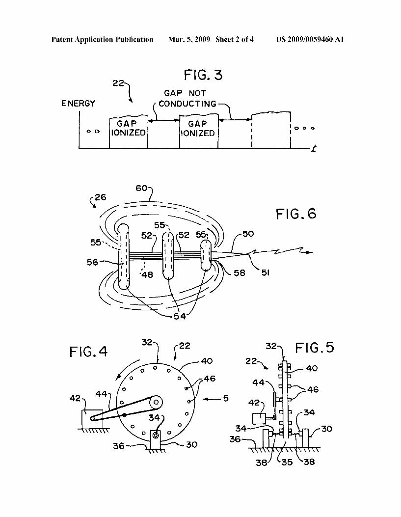
[0017] FIG. 2 is a block diagram of the area generally enclosed by the dotted curve identi?ed by ARROW 2 in FIG. 1 of the tunable and aimable arti?cial lightening producing device of the present invention; [0018] FIG. 3 is an energy V. time diagram of the output of the spark gap shaping apparatus of the tunable and aimable arti?cial lightening producing device of the present invention enclosed by the dotted curve identi?ed by ARROW 3 in FIG. 2; [0019] FIG. 4 is a diagrammatic front elevational vieW of a mechanical embodiment of the spark gap shaping apparatus of the tunable and aimable arti?cial lightening producing device of the present invention enclosed by the dotted curve identi?ed by ARROW 4 in FIG. 2; [0020] FIG. 5 is a diagrammatic side elevational vieW taken generally in the direction of ARROW 5 in FIG. 4; [0021] FIG. 6 is an enlarged diagrammatic side elevational vieW of the area generally enclosed by the dotted curve iden ti?ed by ARROW 6 in FIG. 2 of the ?rst stage directionaliZer of the tunable and aimable arti?cial lightening producing device of the present invention; [0022] FIG. 7 is a diagrammatic side elevational vieW of the area generally enclosed by the dotted curve identi?ed by ARROW 7 in FIG. 2 of a ?rst embodiment of the second stage directionaliZer of the tunable and aimable arti?cial lightening producing device of the present invention; [0023] FIG. 8 is a diagrammatic side elevational vieW of the area generally enclosed by the dotted curve identi?ed by ARROW 8 in FIG. 2 of a second embodiment of the second stage directionaliZer of the tunable and aimable arti?cial lightening producing device of the present invention; [0024] FIG. 9 is a diagrammatic side elevational vieW of the area generally enclosed by the dotted curve identi?ed by ARROW 9 in FIG. 2 of a third embodiment of the second stage directionaliZer of the tunable and aimable arti?cial lightening producing device of the present invention; [0025] FIG. 10 is a diagrammatic side elevational vieW, partly in perspective, broken aWay and in section, of the area generally enclosed by the dotted curve identi?ed by ARROW 10 in FIG. 2 of a fourth embodiment of the second stage directionaliZer of the tunable and aimable arti?cial lightening producing device of the present invention; and [0026] FIG. 11 is an enlarged diagrammatic end elevational vieW taken generally in the direction of ARROW 11 in FIG. 10.
LIST OF REFERENCE NUMERALS UTILIZED IN THE DRAWING
[0027] 20 tunable and aimable arti?cial lightening produc ing device of present invention [0028] 22 spark gap shaping apparatus [0029] 24 Tesla coil [0030] 25 output of Tesla coil 24 [0031] 26 ?rst stage directionaliZer [0032] 27 output of ?rst stage directionaliZer 26 [0033] 28 second stage directionaliZer [0034] 29 converging point of second stage directionaliZer 28 [0035] 30 stationary spark gap assembly of spark gap shap ing apparatus 22 [0036] 31 second converging point of second stage direc tionaliZer 28 [0037] 32 rotational conductor of spark gap shaping appa ratus 22
Mar. 5, 2009
[0038] 33 third converging point of second stage direction aliZer 28 [0039] 34 pair of electrodes of stationary spark gap assem bly 30 of spark gap shaping apparatus 22 [0040] 35 gap betWeen pair of electrodes 34 of stationary spark gap assembly 30 of spark gap shaping apparatus 22 [0041] 36 surface [0042] 38 spark [0043] 40 Wheel of rotational conductor 32 of spark gap shaping apparatus 22 [0044] 42 motor of rotational conductor 32 of spark gap shaping apparatus 22 [0045] 44 pulley and belt system of rotational conductor 32 of spark gap shaping apparatus 22 [0046] 46 plurality of pegs of Wheel 40 of rotational con ductor 32 of spark gap shaping apparatus 22 [0047] 48 shaft of ?rst stage directionaliZer 26 [0048] 50 emitter spike of shaft 48 of ?rst stage direction aliZer 26 [0049] 51 output of emitter spike 50 of shaft 48 of ?rst stage directionaliZer 26 [0050] 52 at least one Wire mesh cage of ?rst stage direc tionaliZer 26 [0051] 54 plurality of torus-shaped discs of ?rst stage direc tionaliZer 26 [0052] 55 holloW centers of torus-shaped disk 54 [0053] 56 large proximal torus-shaped disc of plurality of torus-shaped discs 54 of ?rst stage directionaliZer 26 [0054] 58 small distal torus-shaped disc of plurality of torus-shaped discs 54 of ?rst stage directionaliZer 26 [0055] 60 Warped oval-shaped plasma ?eld of ?rst stage directionaliZer 26
First Embodiment
[0056] 128 second stage directionaliZer [0057] 162 plurality of lasers of second stage directional iZer 128 [0058] 164 controller of second stage directionaliZer 128 [0059] 166 beams generated by plurality of lasers 162 of second stage directionaliZer 128
Second Embodiment
[0060] 228 second stage directionaliZer [0061] 262 plurality of lasers of second stage directional iZer 228 [0062] 263 plurality of prisms of second stage directional iZer 228 [0063] 264 controller of second stage directionaliZer 228 [0064] 266 beams generated by plurality of lasers 262 of second stage directionaliZer 228
Third Embodiment
[0065] 328 second stage directionaliZer [0066] 362 plurality of lasers of second stage directional iZer 328 [0067] 363 plurality of mirrors of second stage directional iZer 328 [0068] 364 controller of second stage directionaliZer 328 [0069] 366 beams generated by plurality of lasers 362 of second stage directionaliZer 328

US 2009/0059460 A1
Fourth Embodiment
[0070] 428 second stage directionaliZer [0071] 462 plurality of lasers of second stage directional iZer 428 [0072] 464 open-ended tube of second stage directionaliZer 428 [0073] 466 ?xed concave lens of second stage directional iZer 428 [0074] 468 movable convex lens of second stage direction aliZer 428 [0075] 469 focal lens of second stage directionaliZer 428 [0076] 470 beaming end of open-ended tube 464 of second stage directionaliZer 428 [0077] 472 beams of plurality of lasers 462 of second stage directionaliZer 428 [0078] 474 controller of second stage directionaliZer 428
DETAILED DESCRIPTION OF THE PREFERRED EMBODIMENT
[0079] Referring noW to the ?gures, in Which like numerals indicate like parts, and particularly to FIGS. 1 and 2, Which are, respectively, a diagrammatic perspective vieW of the tunable and aimable arti?cial lightening producing device of the present invention in use, and, a block diagram of the area generally enclosed by the dotted curve identi?ed by ARROW 2 in FIG. 1 of the tunable and aimable arti?cial lightening producing device of the present invention. The tunable and aimable arti?cial lightening producing device of the present invention is shoWn generally at 20. [0080] The tunable and aimable arti?cial lightening pro ducing device 20 does the folloWing: [0081] l. Creates bolts of arti?cial lightning; [0082] 2. Tunes those bolts of lightning to frequencies that can tetaniZe human voluntary muscle, disable vehicular elec tronic ignition systems, and pre-detonate Wired explosives; [0083] 3. Is able to aim and then direct those bolts of light ning toWard a target; and [0084] 4. Is able to reach great potential distances through the extension of the arti?cial lightning. [0085] The tunable and aimable arti?cial lightening pro ducing device 20 comprises a spark gap shaping apparatus 22, a Tesla coil 24 having an output 25, a ?rst stage directionaliZer 26 having an output 27, and a second stage directionaliZer 28. [0086] The Tesla coil 244called a “resonance transform ers”ihas an ability to create arti?cial lightning, but this is a crude and un-tuned, non-directional energy that has random effects and is primarily used for shoW. [0087] The Tesla coil 24 comprises tWo inductive-capaci tive (LC) oscillatorsia primary and a secondaryibeing loosely coupled to one another. Each LC oscillator has tWo main components being an IIIdUCIOI‘iWhICh has inductance L measured in Henrysiand a capacitoriWith capacitance C measured in Farads. [0088] The inductor of each LC oscillator converts an elec trical current represented by the symbol I and measured in Amperes into a magnetic ?eld, represented by the symbol B and measured in Tesla or a magnetic ?eld into a current. The inductor of each LC oscillator is formed from electrical con ductors Wound into coils. [0089] The capacitor of each LC oscillator comprises tWo or more conductors separated by an insulator. The capacitor of each LC oscillator converts current into an electric ?eld represented by the symbol V and measured in Volts or an
Mar. 5, 2009
electric ?eld into current. Both magnetic ?elds and electric ?elds are forms of stored energy represented by the symbol U and measured in Joules. [0090] When a charged capacitor, U:CV2/2, is connected to an inductor, an electric current ?oWs from the capacitor through the inductor creating a magnetic ?eld, U:Ll2/2. When the electric ?eld in the capacitor is exhausted, the current stops and the magnetic ?eld collapses. As the mag netic ?eld collapses, it induces a current to How in the induc tor in the opposite direction to the original current. This neW current charges the capacitor thereby creating a neW electric ?eldiequal but opposite to the original ?eld. As long as the inductor and capacitor are connected, the energy in the sys tem Will oscillate betWeen the magnetic ?eld and the electric ?eld as the current constantly reverses. [0091] The rateisymbol v and measured in Hertziat Which the system oscillates is given by the (square root of l/LC)/2 pi. In practice, the oscillation eventually dampens out due to resistive losses in the conductors and the excess energy is dissipated as heat. [0092] In the Tesla coil 24, the tWo inductors share the same axis and are located close to one another. In this manner, the magnetic ?eld produced by one inductor generates a current in the other. [0093] The primary oscillator comprises a ?at spiral induc tor With only a feW turns, a capacitor, a voltage source to charge the capacitor, and a sWitch to connect the capacitor to the inductor. The secondary oscillator contains a large, tightly Wound inductor With many turns and a capacitor formed by the earth on one endithe baseiand an output terminali toroidion the other. [0094] While the sWitch is open, a loW currentilimited by the sourcei?oWs through the primary inductor, charging the capacitor. When the sWitch is closed, a much higher current ?oWs from the capacitor through the primary inductor. The resulting magnetic ?eld induces a corresponding current in the secondary. Because the secondary contains many more turns than the primary, a very high electric ?eld is established in the secondary capacitor. [0095] The Tesla coil 24 can be frequency tuned by alter nating the pulse Width by using MOSFET drivers as a sWitch, thereby alloWing for control of the pulse rate and thus repli cating tetaniZing frequency. [0096] The output 25 of the Tesla coil 24 is maximiZed When tWo conditions are met. First both the primary and secondary oscillate at the same frequency. Secondly the total length of the conductor in the secondary is equal to one quarter of the oscillator s Wavelength. A Wavelengthisym bol X and measured in metersiis equal to the speed of lighti300,000,000 meters per secondidivided by the fre quency of the oscillator. [0097] The spark gap shaping apparatus 22 controls the Tesla coil 24. The ?rst stage directionialiZer 26 directs the output 25 of the Tesla coil 24. The second stage directional iZer 28 directs the output 27 of the ?rst stage directionaliZer 26.
[0098] The second stage directionaliZer 28 convergesito a converging point 29imultiple laser beams, microWave beams, or even focused UV lightijust ahead of the plasma ?eld created by the ?rst stage directionaliZer 26. [0099] The converging point 29iat Which the beams meetiioniZes just that point of air Without ioniZing the beam. Once the converging point 29 is arced to by the spark, a second converging point 31, a third converging point 33, and

US 2009/0059460 A1
so on is successively formed Just ahead of the newly estab lished shaped plasma ?eldithe beams ioniZe Just a point and then move that point Just ahead of the spark maintaining the ionization of the trail. This plasma ?eld then goes from being shaped like a sphere to being shaped like a coneiand then ultimately to being shaped like a spike. This spike alloWs for the tuned energy to be directed at a target at great distances.
[0100] The trail is limited only by the ioniZation potential of the plasma ?eld created by the Tesla coil 24. This effect conceivably has a longer range With higher poWer inputsi potentially 20 to 50 times the spark range of just the ?rst stage directionaliZer 26 alone. For example, if the Tesla coil 24 has a spark of 5 feet, then use of the ?rst stage directionaliZer 26 and the second stage directionaliZer 28 could extend that range to betWeen 100 and 250 feet.
[0101] The speci?c con?guration of the spark gap shaping apparatus 22 can best be seen in FIGS. 3-5, Which are, respec tively, an energy v. time diagram of the output of the spark gap shaping apparatus of the tunable and aimable arti?cial light ening producing device of the present invention enclosed by the dotted curve identi?ed by ARROW 3 in FIG. 2, a diagram matic front elevational vieW of a mechanical embodiment of the spark gap shaping apparatus of the tunable and aimable arti?cial lightening producing device of the present invention enclosed by the dotted curve identi?ed by ARROW 4 in FIG. 2, and, a diagrammatic side elevational vieW taken generally in the direction of ARROW 5 in FIG. 4, and as such, Will be discussed With reference thereto.
[0102] As shoWn in FIG. 3, the spark gap shaping apparatus 22 provides alternating gap ioniZation and de-ioniZation to control the Tesla coil 24. [0103] In an electrical version of the spark gap shaping apparatus 22, the primary circuit is knoWn as a tank circuit that controls pulse Width and length. In its simplest form, the spark gap shaping apparatus 22 has tWo conductors separated by an air gap.
[0104] When the electric ?eld stored in the capacitor of the tank circuit reaches a level su?icient to ioniZe the air Within the gap, highly conductive plasma is formed effectively clos ing the spark gap shaping apparatus 22. [0105] Spark gap sWitched coils of the tank circuit operate With inputs of approximately 50,000 volts and produce out puts of several million volts. For the spark gap to be effective, it must be able to open rapidly after the primary oscillation has dampened out in order that the capacitor may recharge. This is achieved by several, methodsiall of Which amount to Ways of cooling and dissipating the hot plasma formed during conduction.
[0106] The output spark of the spark gap shaping apparatus 22 is the result of the creation and collapse of the output plasma ?eld created When resonance is reachedicalibrated for the correct capacitance and induction.
[0107] The spark gap shaping apparatus 22 sWitches up to 150,000 Watts of input poWer. Forced air-cooling of the gap and/ or using a number of gaps in series increases poWer handling. The higher poWer levels of the tunable and aimable arti?cial lightening producing device 20 require a rotary gap that mechanically moves gap electrodes rapidly into and out of conduction range.
[0108] As shoWn in FIGS. 4 and 5, in a mechanical version of the spark gap shaping apparatus 22, the spark gap shaping apparatus 22 comprises a stationary spark gap assembly 30 and a rotational conductor 32.
Mar. 5, 2009
[0109] The stationary spark gap assembly 30 of the spark gap shaping apparatus 22 comprises a pair of electrodes 34. The pair of electrodes 34 of the stationary spark gap assembly 30 of the spark gap shaping apparatus 22 are spaced-apart from each other so as to form a gap 35 there betWeen, are supported on a surface 36, and conduct a spark 38 there betWeen to the Tesla coil 24.
[0110] The rotational conductor 32 of the spark gap shap ing apparatus 22 comprises a Wheel 40. The Wheel 40 of the rotational conductor 32 of the spark gap shaping apparatus 22 is rotatably mounted at a speed of 1200-1800 rpms in the gap 35 betWeen, and spaced-apart from, the pair of electrodes 14 of the stationary spark gap assembly 30 of the spark gap shaping apparatus 22. [0111] The diameter of the Wheel 40 of the rotational con ductor 32 of the spark gap shaping apparatus 22 can be changed for changing pulse rate. [0112] The Wheel 40 of the rotational conductor 32 of the spark gap shaping apparatus 22 is rotated by a motor 42. The motor 42 of the rotational conductor 32 of the spark gap shaping apparatus 22 is preferablyAC, and is connected to the Wheel 40 of the rotational conductor 32 of the spark gap shaping apparatus 22 by a pulley and belt system 44. [0113] The Wheel 40 of the rotational conductor 32 of the spark gap shaping apparatus 22 has a plurality of pegs 46. The plurality of pegs 46 of the Wheel 40 of the rotational conduc tor 32 of the spark gap shaping apparatus 22 extend there through and there around, and are electrically conductive so as to make the gap 35 betWeen the pair of electrodes 34 of the stationary spark gap assembly 30 of the spark gap shaping apparatus 22 electrically conductive When a peg 46 of the Wheel 40 of the rotational conductor 32 of the spark gap shaping apparatus 22 aligns With the pair of electrodes 34 of the stationary spark gap assembly 30 of the spark gap shaping apparatus 22. [0114] The plurality of pegs 46 of the Wheel 40 of the rotational conductor 32 of the spark gap shaping apparatus 22 are adjustableithey can be increased or decreased in number and/or positioned changedifor changing pulse rate. [0115] A standard untuned frequency of a Tesla coil exceeds 50,000 HZ. By spinning the rotary spark gap at around 1500 RPM, a 25:1 reduction takes place creating a pulse at 1/20 the rate of the standard frequencyithereby bringing What is perceived to the targeted muscle group as a tetaniZing frequency and pulse shape. The frequency at Which muscle is tetanizedineuromuscularly disruptediranges from 1700 to 2500 Hertz.
[0116] To adjust pulse rate, a manual adjustment of either the pulley and belt system 44 of the rotational conductor 32 of the spark gap shaping apparatus 22 or an adjustment of the speed of the motor 42 of the rotational conductor 32 of the spark gap shaping apparatus 22 is required. [0117] The speci?c con?guration of the ?rst stage direc tionaliZer 26 can best be seen in FIG. 6, Which is an enlarged diagrammatic side elevational vieW of the area generally enclosed by the dotted curve identi?ed by ARROW 6 in FIG. 2 of the ?rst stage directionaliZer of the tunable and aimable arti?cial lightening producing device of the present invention, and as such, Will be discussed With reference thereto.
[0118] The ?rst stage directionaliZer 26 comprises a shaft 48 terminating in an emitter spike 50 having an output 51, at least one Wire mesh cage 52, and a plurality of torus-shaped discs 54.

US 2009/0059460 A1
[0119] The emitter spike 50 of the shaft 48 of the ?rst stage directionaliZer 26 is preferably made of brass, and is retract able and extendably movably mounted to optimize direction ality. [0120] The plurality of torus-shaped discs 54 of the ?rst stage directionaliZer 26 are preferably made of heavy hollow aluminum or steel, are parallel to each other, are spaced-apart from each other, have holloW centers 55, are stacked perpen dicularly to the secondary coil of the Tesla coil 24, and pro gressively decrease in diameter from a large proximal torus shaped disc 56 to a small distal torus-shaped disc 58ithat is furthest aWay from the Tesla coil 24. [0121] The shaft 48 of the ?rst stage directionaliZer 26 is preferably made of holloW threaded steel, and passes cen trally throughiso as to connect to each otherithe plurality of torus-shaped discs 54 of the ?rst stage directionaliZer 26, from the large proximal torus-shaped disc 56 of the ?rst stage directionaliZer 26iWhere it electrically communicates With the output 25 of the Tesla coil 24ito the small distal torus shaped disc 58 of the ?rst stage directionaliZer 26iWhere it becomes the emitter spike 50. [0122] The at least one Wire mesh cage 52 of the ?rst stage directionaliZer 26 is preferably heavy gauge, can be replaced by support rods, surrounds the shaft 48 of the ?rst stage directionaliZer 26, betWeen adjacent torus-shaped discs 54 of the ?rst stage directionaliZer 26, from the large proximal torus-shaped disc 56 of the ?rst stage directionaliZer 26 to the small distal torus-shaped disc 58 of the ?rst stage direction aliZer 26. [0123] The ?rst stage directionaliZer 26 Warps the normally spherical plasma ?eld into the shape of a “football” so as to form a Warped oval-shaped plasma ?eld 60. The Warped oval-shaped plasma ?eld 60 of the ?rst stage directionaliZer 26 forces the output 51 of the emitter spike 50 of the shaft 48 of the ?rst stage directionaliZer 26 to be pressed from all sides into a column.
[0124] The Warped oval-shaped plasma ?eld 60 of the ?rst stage directionaliZer 26 is established and collapsed at a rate of betWeen 20,000 and 50,000 times a secondimeaning that although a long, seemingly single spark is visible to the naked eye, in fact as many as 50,000 individual sparks are being created every second. [0125] The rate of collapse of the Warped oval-shaped plasma ?eld 60 of the ?rst stage directionaliZer 26 can be regulated through an output sWitch and sent to, and distrib uted among, multiple detached emitter spikes 50 of the shaft 48 of the ?rst stage directionaliZer 26. [0126] For example, if ?ve emitter spikes 50 of the shaft 48 of the ?rst stage directionaliZer 26 are attached to a single Tesla coil 24 ?ring at 50,000 sparks per second, each emitter spike 50 of the shaft 48 of the ?rst stage directionaliZer 26 Would be able to ?re 10,000 sparks per secondiWhich Would be undetectable to the human eye and Would not detract from the effectiveness of the tunable and aimable arti?cial lighten ing producing device 20 on its target or in its intimidation effect. [0127] Essentially, the ?rst stage directionaliZer 26 alloWs the normally spherical plasma ?eld to create a static charge around the plurality of torus-shaped discs 54 of the ?rst stage directionaliZer 26, and then discharge off the emitter spike 50 of the shaft 48 of the ?rst stage directionaliZer 26. [0128] The plurality of torus-shaped discs 54 of the ?rst stage directionaliZer 26 force the plasma ?eld created by the Tesla coil 24 to become more conically shaped and the emitter
Mar. 5, 2009
spike 50 of the shaft 48 of the ?rst stage directionaliZer 26 puts the “point” on the coneialloWing for all the tuned lightning to be ?red at a speci?c target at closer range. [0129] A ?rst embodiment of a second stage directionaliZer 128 can best be seen in FIG. 7, Which is a diagrammatic side elevational vieW of the area generally enclosed by the dotted curve identi?ed by ARROW 7 in FIG. 2 of a ?rst embodiment of the second stage directionaliZer of the tunable and aimable arti?cial lightening producing device of the present invention, and as such, Will be discussed With reference thereto. [0130] The second stage directionaliZer 128 comprises a plurality of lasers 162. [0131] The plurality of lasers 162 of the second stage direc tionaliZer 128 are operatively connected to each other and to a controller 164.
[0132] The controller 164 of the second stage directional iZer 128 causes the plurality of lasers 162 of the second stage directionaliZer 128 to pivot in concert to cause convergence of beams 166 generated by the plurality of lasers 162 of the second stage directionaliZer 128. [0133] The second embodiment of the second stage direc tionaliZer 228 can best be seen in FIG. 8, Which is a diagram matic side elevational vieW of the area generally enclosed by the dotted curve identi?ed by ARROW 8 in FIG. 2 of a second embodiment of the second stage directionaliZer of the tunable and aimable arti?cial lightening producing device of the present invention, and as such, Will be discussed With refer ence thereto.
[0134] A second stage directionaliZer 228 comprises a plu rality of lasers 262 and a plurality of prisms 263. [0135] The plurality of prisms 263 of the second stage directionaliZer 228 are operatively connected to each other and to a controller 264.
[0136] The controller 264 of the second stage directional iZer 228 causes the plurality of prisms 263 of the second stage directionaliZer 128 to pivot in concert and cause convergence of beams 266 generated by the plurality of lasers 262 of the second stage directionaliZer 228. [0137] A third embodiment of a second stage directional iZer 328 can best be seen in FIG. 9, Which is a diagrammatic side elevational vieW of the area generally enclosed by the dotted curve identi?ed by ARROW 9 in FIG. 2 of a third embodiment of the second stage directionaliZer of the tunable and aimable arti?cial lightening producing device of the present invention, and as such, Will be discussed With refer ence thereto.
[0138] The second stage directionaliZer 328 comprises a plurality of lasers 362 and a plurality of mirrors 363. [0139] The plurality of mirrors 363 of the second stage directionaliZer 328 are operatively connected to each other and to a controller 364.
[0140] The controller 364 of the second stage directional iZer 328 causes the plurality of mirrors 363 of the second stage directionaliZer 328 to pivot in concert and cause con vergence of beams 366 generated by the plurality of lasers 362 of the second stage directionaliZer 328. [0141] A fourth embodiment of a second stage directional iZer 428 can best be seen in FIGS. 10 and 11, Which are, respectively, a diagrammatic side elevational vieW partly in perspective, broken aWay and in section of the area generally enclosed by the dotted curve identi?ed by ARROW 1 0 in FIG. 2 of a fourth embodiment of the second stage directionaliZer of the tunable and aimable arti?cial lightening producing device of the present invention, and, an enlarged diagram

US 2009/0059460 A1
matic end elevational vieW taken generally in the direction of ARROW 11 in FIG. 10, and as such, Will be discussed With reference thereto. [0142] The second stage directionaliZer 428 comprises a plurality of lasers 462, an open-ended tube 464, a ?xed con cave lens 466, a movable convex lens 468, and a focal lens 469. [0143] The ?xed concave lens 466 of the second stage directionaliZer 428 is ?xed Within the open-ended tube 464 of the second stage directionaliZer 428, in proximity to a beam ing end 470 thereof, at Which the focal lens 469 of the second stage directionaliZer 428 is disposed. [0144] The movable convex lens 468 of the second stage directionaliZer 428 is movably disposed Within the open ended tube 464 of the second stage directionaliZer 428, adja cent to, and in optical communication With, the ?xed concave lens 466 of the second stage directionaliZer 428. [0145] The plurality of lasers 462 of the second stage direc tionaliZer 428 are disposed outside the other end of the open ended tube 464 of the second stage directionaliZer 428, and direct beams 472 through the open-ended tube 464 of the second stage directionaliZer 428, to and through the ?xed concave lens 466 of the second stage directionaliZer 428, to and through the movable convex lens 468 of the second stage directionaliZer 428, Whose movement is controlled by a con troller 474, and to and through the focal lens 469 of the second stage directionaliZer 428. [0146] The ?xed concave lens 466 of the second stage directionaliZer 428 and the movable convex lens 468 of the second stage directionaliZer 428 are close coupled to each other to create a collimator lens assembly. The beams 472 of the plurality of lasers 462 of the second stage directionaliZer 428 are columnated and passed through the focal lens 469 of the second stage directionaliZer 428 that tightens the beams 472 of the plurality of lasers 462 of the second stage direc tionaliZer 428 to a point. [0147] The beams 472 of the plurality of lasers 462 of the second stage directionaliZer 428 are compressed into a single beam that is focused onto a single point and then movediby changing focal lengthiinto the distance by Way of the mov able convex lens 468 of the second stage directionaliZer 428. [0148] It Will be understood that each of the elements described above, or tWo or more together, may also ?nd a useful application in other types of constructions differing from the types described above. [0149] While the invention has been illustrated and described as embodied in a tunable and aimable arti?cial lightening producing device, hoWever, it is not limited to the details shoWn, since it Will be understood that various omis sions, modi?cations, substitutions and changes in the forms and details of the device illustrated and its operation can be made by those skilled in the art Without departing in any Way from the spirit of the present invention. [0150] Without further analysis, the foregoing Will so fully reveal the gist of the present invention that others can, by applying current knowledge, readily adapt it for various applications Without omitting features that, from the stand point of prior art, fairly constitute characteristics of the generic or speci?c aspects of this invention.
1-44. (canceled) 45. An apparatus comprising: a spark gap shaping apparatus; a resonance transformer comprising a primary coil electro
magnetically coupled to a secondary coil, said reso
Mar. 5, 2009
nance transformer coupled to said spark gap shaping apparatus, and said resonance transformer having an output;
an emitter coupled to the output of said resonance trans former; and
a second stage directionaliZer comprising a plurality of electromagnetic beam generators each operable to emit an electromagnetic energy beam, Wherein the second stage directionaliZer is operable to focus the electromag netic energy beams on a convergence point that can be moved to successive locations to create an ioniZation path, and Wherein each electromagnetic energy beam does not individually ioniZe the air through Which it travels.
46. The apparatus of claim 45, further comprising a ?rst stage directionaliZer coupled betWeen the output of said reso nance transformer and said emitter, Wherein said ?rst stage directionaliZer is operable to Warp a normally spherical plasma ?eld from said resonance transformer into a substan tially oval shaped plasma ?eld.
47. The apparatus of claim 46, Wherein said ?rst stage directionaliZer comprises a plurality of torus-shaped discs.
48. The apparatus of claim 47, Wherein said plurality of torus-shaped discs are spaced apart and are arranged parallel to each other.
49. The apparatus of claim 48, Wherein said plurality of torus-shaped discs progressively decrease in diameter from said resonance transformer to said emitter.
50. The apparatus of claim 49, further comprising a holloW shaft passing through said plurality of torus-shaped discs.
51. The apparatus of claim 46, Wherein said ?rst stage directionaliZer comprises a Wire mesh cage.
52. The apparatus of claim 47, Wherein said plurality of torus-shaped discs are made of aluminum.
53. The apparatus of claim 45, further comprising at least one MOSFET drive operable to be used as a sWitch to alter nate the pulse Width to frequency tune said resonance trans former, thereby alloWing control of the pulse rate.
54. The apparatus of claim 53, Wherein the pulse rate replicates a tentaniZing frequency.
55. The apparatus of claim 46, Wherein said Warped plasma ?eld of said ?rst stage directionaliZer is established and col lapsed at a rate betWeen 20,000 and 50,000 times a second.
56. The apparatus of claim 55, further comprising an output sWitch and multiple detached emitters, Wherein said rate of collapse of said Warped plasma ?eld of said ?rst stage direc tionaliZer is regulated through said output sWitch and is sent to, and distributed among, the multiple detached emitters.
57. The apparatus of claim 45, Wherein said plurality of electromagnetic beam generators are selected from the group consisting of: lasers, microWave generators, and focused UV light generators.
58. The apparatus of claim 45, Wherein said plurality of electromagnetic beam generators are lasers.
59. The apparatus of claim 1, further comprising a control ler operatively connected to said plurality of electromagnetic beam generators.
60. The apparatus of claim 59, further comprising a means to target saidplurality of electromagnetic beams to successive locations, said means operatively connected to said controller and Wherein said controller is operable to target said plurality of electromagnetic beams in concert to cause convergence of said plurality of electromagnetic beams.

US 2009/0059460 A1
61. The apparatus of claim 60, wherein said means is selected from the group consisting of: a plurality of prisms, a plurality of mirrors, and a tube containing a ?xed concave lens, a movable convex lens and a focal lens.
62. The apparatus of claim 45, Wherein said resonance transformer is a Tesla Coil.
63. The apparatus of claim 45, Wherein the output of said resonance transformer is in excess of one million volts of electrical potential.
64. A method of proj ecting lightening comprising the steps of:
a) providing an arti?cial lightening producing device com prising: a spark shaping apparatus, a resonance trans former comprising a primary coil electromagnetically coupled to a secondary coil coupled to the spark shaping apparatus, an emitter coupled to the secondary coil of the resonance transformer, and a second stage directional iZer comprising a plurality of electromagnetic beam generators operable to ioniZe air in unison but not indi vidually;
Mar. 5, 2009
b) generating a electric potential in the emitter With the resonance transformer;
c) With the plurality of electromagnetic beam generators, ioniZing the air at a converging point proximate to the emitter;
d) moving the converging point progressively from a point proximate to the emitter to a point proximate to a target, creating a path of ioniZed air; and
e) discharging the electric potential to the target through the path of ioniZed air.
65. The method of claim 64, further comprising the step of: f) tuning the frequency of the resonance transformer to
replicate a tentaniZing frequency. 66. The method of claim 64, further comprising the step of: g) selecting the plurality of electromagnetic beam genera
tors from the group consisting of: lasers, microWave generators, and focused UV light generators.
* * * * *