urbana 2015 1 - fluorescencefluorescence-foundation.org/lectures/champaign2015/seminar1.pdfurbana...
TRANSCRIPT

David Jameson 3/23/2015
Urbana 2015 1
Basic Instrumentation: David Jameson(some of these slides were prepared by
Theodore “Chip” Hazlett and Joachim Müller)
Principles of Fluorescence Techniques 2015 Urbana-Champaign, Illinois
April 6-9, 2015
Sample
Light Source
The Basics
WavelengthSelection
WavelengthSelection
Polarizer
Polarizer
computer
Detector
The Laboratory Fluorimeter
Pem
Pex
Pem
ISS (Champaign, IL, USA) PC1 Fluorimeter
Standard Light Source: Xenon Arc Lamp
Exit Slit

David Jameson 3/23/2015
Urbana 2015 2
Light Sources
Light Sources
Lamp Light Sources
Gas discharge lamps
Xenon Arc Lamp (wide range of wavelengths)
Xenon Arc Lamp Profiles
These lamps use tungsten electrodes and xenon gas at pressures up to 25 atmospheres
Ozone Free
A UV-blocking material can be used to coat the interior of the bulb envelope which prevents the production of ozone outside of the lamp housing
Introduced in 1951 by the Osram Company
http://jp.hamamatsu.com/resources/products/etd/eng/image/xe_hgxe_003.jpg

David Jameson 3/23/2015
Urbana 2015 3
Lamp Light Sources
High Pressure Mercury Lamps (High Intensities concentrated in specific lines)
There are strong lines near 254nm, 297nm, 333nm, 365nm, 405nm, 436nm, 546nm and 568nm
Gas discharge lamps
Lamp Light Sources
UV Handlamps usually provide for “short – 254nm” or “long – 365nm” illumination
Gas discharge lamps
Lamp Light Sources
Mercury-Xenon Arc Lamp (greater intensities in the UV)
David Jameson 3/23/2015
Urbana 2015 4
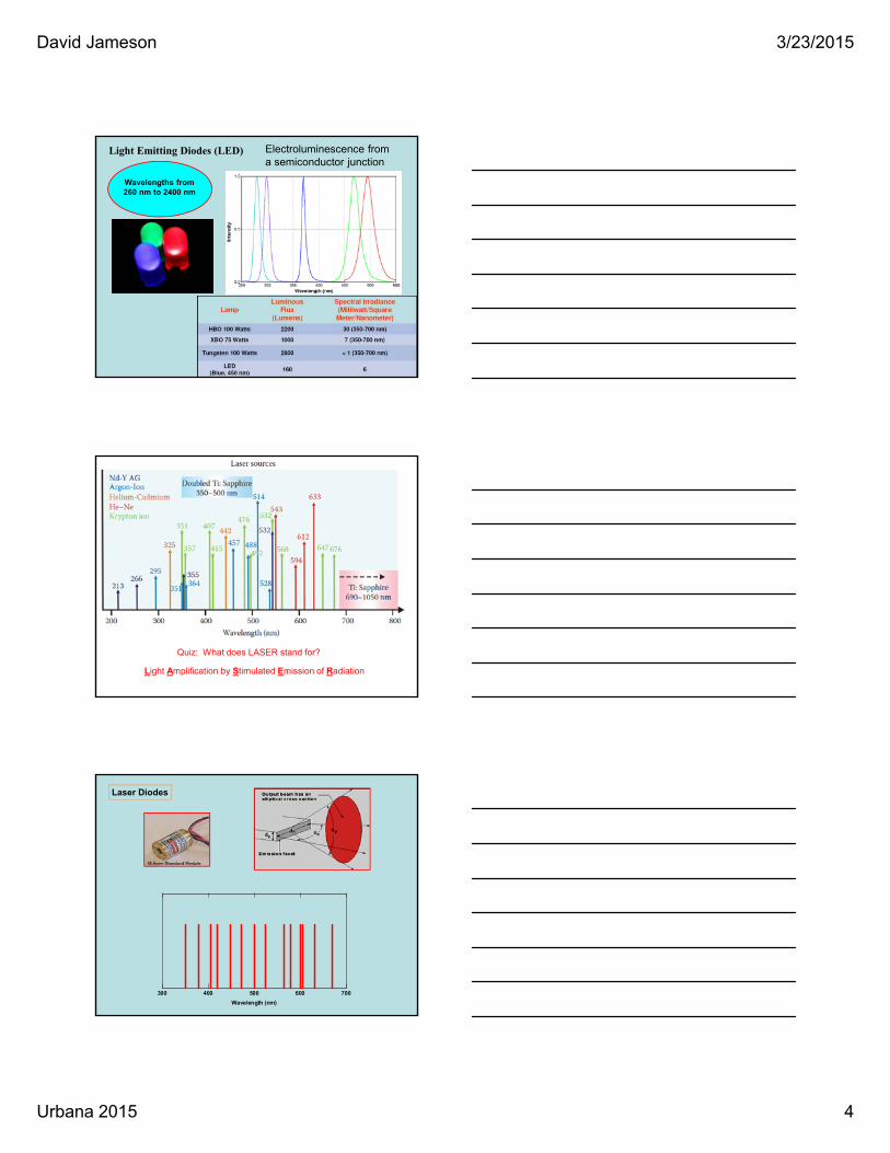
Light Emitting Diodes (LED)
Wavelengths from260 nm to 2400 nm
Electroluminescence from a semiconductor junction
Quiz: What does LASER stand for?
Light Amplification by Stimulated Emission of Radiation
Laser Diodes
700600500400300
Wavelength (nm)

David Jameson 3/23/2015
Urbana 2015 5
“White” lasers
Ultrashort pulsed light is focused into a photonic crystal fiber
New light source being tested in Hawaii
Detectors

David Jameson 3/23/2015
Urbana 2015 6
Detectors
http://www.ndt-ed.org/EducationResources/CommunityCollege/PenetrantTest/Introduction/lightresponse.htm
DetectorsThe photoelectric effect was discovered by Heinrich Hertz in 1886
Specifically he noticed that a charged object loses its charge more readily when it is illuminated by UV light
It was soon discovered that the energies of the ejected electrons were independent of the intensity of the illuminating light, whereas this energy increased with the frequency of the light. This phenomenon as explained by Einstein in 1905 as being due to the quantum nature of light, i.e., photons. Einstein received his Nobel Prize for this work in 1921.
APD
The silicon avalanche photodiode (Si APD) hasa fast time response and high sensitivity in thenear infrared region. APDs can be purchasedfrom Hamamatsu with active areas from 0.2mm to 5.0 mm in diameter and low darkcurrents (selectable). Photo courtesy ofHamamatsu
Detectors

David Jameson 3/23/2015
Urbana 2015 7
DynodesPhotocathode
High Voltage Supply(-1000 to -2000 V)
Ground
e-Anode
Current Output
e-
e-e-
Constant Voltage (use of a Zenor Diode)
resister series
(voltage divider) capacitor series(current source)
e-
e-e-e-
e-e-
e-
e-e-
Vacuum
The Classic Photomultiplier Tube (PMT) Design
Window
Photomultipliers were developed in the 1930’s but not generally adopted for research until after WWII
Hamamatsu R928 PMT Family
Window withPhotocathode Beneath
R2949

David Jameson 3/23/2015
Urbana 2015 8
Cathode Material
Window Material
PMT Quantum Efficiencies
APD
The silicon avalanche photodiode(Si APD) has a fast time responseand high sensitivity in the nearinfrared region. APDs can bepurchased from Hamamatsu withactive areas from 0.2 mm to 5.0mm in diameter and low darkcurrents (selectable). Photocourtesy of Hamamatsu
Detectors
APDs are usually used in applications characterized by low light levels
Photon Counting (Digital) and Analog Detection
Primary Advantages:1. Sensitivity (high signal/noise)2. Increased measurement stability
Primary Advantage:1. Broad dynamic range2. Adjustable range
Sig
nal
time
Constant High Voltage Supply
DiscriminatorSets Level
PMT
TTL Output(1 photon = 1 pulse)
PMT
Variable Voltage Supply
Computer
Anode Current=
Pulse averaging
Continuous Current Measurement
Photon Counting: Analog:
level

David Jameson 3/23/2015
Urbana 2015 9
Wavelength Selection
Fixed Optical Filters
Tunable Optical Filters
Monochromators
Optical Filter Channel
Pem
Pex
Pem
Long Pass Optical Filters

David Jameson 3/23/2015
Urbana 2015 10
100
80
60
40
20
0700600500400300
More Optical Filter Types…Tr
an
sm
iss
ion
(%
)
Wavelength (nm)
Interference Filters(Chroma Technologies)
Broad Bandpass Filter(Hoya U330)
Neutral Density(Coherent Lasers)
http://www.juliantrubin.com/bigten/lightexperiments.html
Monochromators
http://www.juliantrubin.com/bigten/lightexperiments.html
People had experimented with prisms and light before Newton – but generally it was thought that the prism somehow “colored” the light. Newton was the first to clearly state that the prism revealed an underlying characteristic of white lght – namely that it was composed of many colors.

David Jameson 3/23/2015
Urbana 2015 11
Monochromators
http://www.wooster.edu/chemistry/is/brubaker/uv/uv_landmark.html#1
An important impetous to the development of optical spectroscopy was the discovery that vitamin A had a characteristic absorption in the ultraviolet region of the spectrum. The Government was very interested in the development of methods to measure and characterize the vitamin content of foods. This initiative eventually led to the Beckman DU UV-vis spectrophotometer
The earliest commercial fluorescence instruments were essentially attachments for spectrophotometers such as the Beckman DU spectrophotometer; this attachment allowed the emitted light (excited by the mercury vapor source through a filter) to be reflected into the spectrophotometer’s monochromator. The first description of this type of apparatus was by R.A. Burdett and L.C. Jones in 1947 (J. Opt. Soc. Amer. 37:554).
The problem with prisms, however, was that the light dispersion was not linear with wavelength and normal glass prisms did not pass UV light – so expensive quartz prism had to be used. For these reasons grating based systems became more popular.
Diffraction Gratings
Formerly ruled with diamond-tipped instruments
Now almost always made using a holographic, photolithographic technique or a photosensitive gel method
http://gratings.newport.com/products/supplemental/types.asp

David Jameson 3/23/2015
Urbana 2015 12
Monochromators
Czerny-Turner design
Mirrors
Rotating Diffraction Grating(Planar or Concaved)
Entrance slit
Exit Slit
1. Slit Width (mm) is the dimension of the slits.
2. Bandpass is the FWHM of the selected wavelength.
3. The dispersion is the factor to convert slit width to bandpass.
Zero Order(acts like a mirror)
Nth Order(spectral distribution)
Mirrors
Grating
The Inside of a Monochromator
1.0
0.8
0.6
0.4
0.2
0.0580560540520
Changing the Bandpass
1.0
0.8
0.6
0.4
0.2
0.0
x106
580560540520
Fixed Excitation Bandpass = 4.25 nm
17 nm
2.125 nm
4.25 nm
8.5 nm
1. Drop in intensity2. Narrowing of the spectral selection
Flu
ore
sc
en
ce
(a
u)
Wavelength (nm)
Changing the Emission BandpassFull Width Half Maximum (FWHM)
Collected on a SPEX Fluoromax - 2
Wavelength (nm)
17 nm
8.5 nm
4.25 nm
2.125 nm

David Jameson 3/23/2015
Urbana 2015 13
Higher Order Light Diffraction
350
300
250
200
150
100
50
0
x1
03
700600500400300200
Wavelength (nm)
Flu
ore
sc
en
ce
(a
u)
Emission Scan:Excitation 300 nmGlycogen in PBS
Excitation (Rayleigh) Scatter(300 nm)
2nd Order Scatter(600 nm)
Water RAMAN(334 nm)
2nd Order RAMAN(668 nm)
Fluorescent Contaminants
For example: Exc Raman280 310350 397480 574
The approximate position of the water Raman peak can be calculated with this formula
Monochromator Polarization Bias
No Polarizer
Parallel Emission
Perpendicular Emission
Wood’s Anomaly
Adapted from Jameson, D.M., Instrumental Refinements in Fluorescence Spectroscopy: Applications to Protein Systems., in Biochemistry, Champaign-Urbana, University of Illinois, 1978.
250
250
800
800
Flu
ore
scen
ce
Flu
ore
scen
ce
Tungsten Lamp Profile Collected on an SLM Fluorometer

David Jameson 3/23/2015
Urbana 2015 14
300 350 400 450 500 550 600
vertical horizontal
Wavelength (nm)
ISSPC1Correction Factors
400 450 500 550 600
Inte
nsity
(a.
u.)
Wavelength (nm)
B
400 450 500 550 600
In
tens
ity (
a.u
.)
Wavelength (nm)
C
Correction of Emission Spectra
from Jameson et. Al., Methods in Enzymology, 360:1
Wavelength Wavelength
Flu
ore
scen
ce
Flu
ore
scen
ceANS Emission Spectrum, no polarizer ANS Emission Spectrum, parallel polarizer
uncorrected
corrected
Wavelength
250 300 350 400 4500.0
0.2
0.4
0.6
0.8
1.0
A
Wavelength (nm)
Excitation Correction
from Jameson, Croney and Moens, Methods in Enzymology, 360:1
Absorption (dotted line) and Excitation Spectra (solid line) of ANS in Ethanol
Uncorrected
Note the huge difference between the absorption spectrum and the excitation spectrum
Flu
ore
scen
ce Recall the output of the xenon arc
Pem
Pex
Pem
Exit Slit
Quantum Counter
Excitation Correction

David Jameson 3/23/2015
Urbana 2015 15
The Instrument Quantum Counter
FluorescenceHere we want the inner filter effect!
Optical Filter
ReferenceDetector
Quantum Counter
Common Quantum Counters (optimal range)*
Rhodamine B (220 - 600 nm)
Fluorescein (240 - 400 nm)
Quinine Sulfate (220 - 340 nm)
* Melhuish (1962) J. Opt. Soc. Amer. 52:1256
Wavelength (nm)200 600400
1.2
0.8
0.4
0.0
Ep
ple
y T
her
mo
pile
/ Q
C
Linearity of Rhodamine as a quantum counter
Excitation Correction
from Jameson, Croney and Moens, Methods in Enzymology, 360:1
250 300 350 400 4500.0
0.2
0.4
0.6
0.8
1.0
B
Wavelength (nm)Wavelength
Flu
ore
scen
ce
Ratio Corrected
Still not perfect since the quartz reflector to the quantum counter has a polarization bias.
250 300 350 400 4500.0
0.2
0.4
0.6
0.8
1.0
C
Wavelength (nm)Wavelength
Flu
ore
scen
ce
Lamp Corrected
If we determine the lamp curve at the sample position and then divide the sample excitation spectrum by this curve we can get excellent agreement
Two UV selected calcite prisms areassembled with an intervening air space. Thecalcite prism is birefringent and cut so that onlyone polarization component continues straightthrough the prisms. The spectral range of thispolarizer is from 250 to 2300 nm. At 250 nmthere is approximately 50% transmittance.
The Glan Taylor prism polarizer
Polarizers
Common Types:
Glan Taylor (air gap)
Glan Thompson
Sheet Polarizers
Two Calcite Prisms
0
90
90
0

David Jameson 3/23/2015
Urbana 2015 16
Attenuation of the Excitation Light through Absorbance
Sample concentration& the inner filter effect
Rhodamine B
from Jameson et. al., Methods in Enzymology (2002), 360:1
0.03 0.3 1.0 3.0
How do we handle highly absorbing solutions?
Quartz/Optical Glass/Plastic Cells
Emission Path Length
Detector
Excitation
Em
issi
on
Excitation Path Length
4 Position Turret SPEX Fluoromax-2, Jobin-Yvon
Front Face Detection
Triangular Cells
Detector
Excitation
Reflected Excitation & Emission
Thin Cells & Special Compartments
Sample
Absorbance Measurements
ExcitationEmission
[1] Adapted from Gryczynski, Lubkowski, & Bucci Methods of Enz. 278: 538
[1]
IBH, Glasgow G3 8JUUnited Kingdom

David Jameson 3/23/2015
Urbana 2015 17
Lifetime Instrumentation
Light Sources for Decay Acquisition:Frequency and Time Domain Measurements
Pulsed Light Sources (frequency & pulse widths)
Mode-Locked LasersND:YAG (76 MHz) (150 ps)Pumped Dye Lasers (4 MHz Cavity Dumped, 10-15 ps)Ti:Sapphire lasers (80 MHz, 150 fs)Mode-locked Argon Ion lasers
Directly Modulated Light SourcesDiode Lasers (short pulses in ps range, & can be modulated by synthesizer)LEDs (directly modulated via synthesizer, 1 ns, 20 MHz) Synchrotron Radiation
Flash LampsThyratron-gated nanosecond flash lamp (PTI), 25 KHz, 1.6 nsCoaxial nanosecond flashlamp (IBH), 10Hz-100kHz, 0.6 ns
Modulation of CW LightUse of a Pockel’s Cell
Mir
ror
Radio FrequencyInput
Pockel’s Cell
Polarizer
Polished on a side exit plane
CW Light Source
Double Pass Pockel’s Cell
Modulated light to sample
The Pockel’s Cell is an electro-optic device that usesthe birefringment properties of calcite crystals toalter the beam path of polarized light. In applyingpower, the index of refraction is changed and thebeam exiting the side emission port (0 polarized) isenhanced or attenuated. In applying RF the outputbecomes modulated.
90
0
Polarizer

David Jameson 3/23/2015
Urbana 2015 18
Time Correlated Single Photon Counting
Pulsed Light Source
PM
T
TAC
Multichannel Analyzer
Constant FractionDiscriminator
Time
Co
un
ts
Sample Compartment
Filter or Monochromator
Time-to-Amplitude Converter (TAC)
Instrument Considerations
Excitation pulse width
Excitation pulse frequency
Timing accuracy
Detector response time (PMTs 0.2-0.9; MCP 0.15 to 0.03 ns)
Photon Counting PMT
Timing Electronics or 2nd PMT Neutral density (reduce to one photon/pulse)
4
6
80.01
2
4
6
80.1
2
4
6
81
300250200150100500
Channels (50 ps)
Flu
ore
sc
en
ce
Fluorescence Decay
Instrument Response Function
Histograms built one photon count at a time …
(1) The pulse width and instrument response times determine the timeresolution.
(2) The pulse frequency also influences the time window. An 80 MHzpulse frequency (Ti:Sapphire laser) would deliver a pulse every 12.5ns and the pulses would interfere with photons arriving later than the12.5 ns time.

David Jameson 3/23/2015
Urbana 2015 19
Frequency Domain Fluorometry
CW Light SourceSample Compartment
Filter or Monochromator
PM
T
Analog PMTs (can also be done with photon counting)
PM
T
S1 = n MHz
S2 = n MHz + 800 kHz
RF
Digital Acquisition Electronics
Signal
Sig
nal
RF
Locking Signal
S1 S2Synthesizers
S1 and S2
Computer Driven Controls
Similar instrument considerations as With TCSPC
Reference Turret
Pockel’s Cell
That’s all!!!