uq ict cabling specification v2.1
TRANSCRIPT

UQ ICT CABLING
UQ ICT Cabling Specification v2.2.docx Page 1
Printed: 2 May, 2017
PHYSICAL LAYER SERVICES GROUP
Telecommunications Cabling Standards Rev2.2

UQ ICT CABLING
UQ ICT Cabling Specification v2.2.docx Page 2
Printed: 2 May, 2017
FUNCTIONAL SPECIFICATION
TABLE OF CONTENTS
1. REVISION HISTORY 6
DETAILED REVISION HISTORY IS SHOWN IN ANNEX R. 6
2. ABBREVIATIONS 6
3. INTRODUCTION 7
4. TRADE NAMES OR BRANDS AND SUBSTITUTIONS 7
5. IMPORTANT INFORMATION 7
6. DOCUMENT SUMMARY 7
6.1 Class of Cabling 7
6.2 Optical Fibre 7
6.3 Independent Third Party Test Result Verification 7
6.4 Horizontal Distribution 7
6.5 Outlet Density 7
6.6 Patch Panel Density 7
6.7 Workstation terminations 8
6.8 Termination Scheme 8
6.9 Testing 8
6.10 Abandoned Cable 8
6.11 Wireless Access Points 8
6.12 Warranty 8
7. SCOPE OF WORKS 8
7.1 In-Scope 8
7.2 Not In-Scope 8
7.3 Instructions 8
8. SYSTEM REQUIREMENTS 9
8.1 Applicable Performance Standards 9
8.2 Quality Standards 9
9. GENERAL INFORMATION 9
9.1 Supported Applications 9
10. INSTALLATION CONTRACTOR 10
10.1 Installation Manager 10
10.2 Installation Team Leader (On-site Supervision) 10
10.3 Installation Team 10
10.4 Parking 10
10.5 Work Health & Safety 10
10.5.1 Change Management 11
10.5.2 Equipment 11
10.6 Travel and Accommodation 11
11. PATHWAYS AND SPACES 11
11.1 General 11
11.2 Telecommunications Rooms 11
11.3 Horizontal Distribution 11
11.3.1 General 12
11.3.2 Cable Tray 12

UQ ICT CABLING
UQ ICT Cabling Specification v2.2.docx Page 3
Printed: 2 May, 2017
11.3.3 Cable Mesh 12
11.3.4 Catenary Wire Support Systems 12
11.4 Segregation 13
11.5 Vertical Riser Cabling 13
11.6 Core Holes 13
11.7 External Pathways (Outside Plant) 13
11.7.1 Pit and pipe 13
12. INSTALLATION STANDARDS 14
12.1 xTP Installation 14
12.1.1 General 14
12.1.2 Cable Installation 15
12.1.3 Patch Panel Installation 15
12.1.4 Consolidation Points 16
12.1.5 Multi User Telecommunications Outlet Assembly 16
12.2 Optical Fibre Cable Installation 16
12.2.1 General 16
12.2.2 Single Mode 17
12.2.3 Multimode 17
12.2.4 FOBOTS 17
12.3 Earthing 17
12.4 Fire Rated Barriers 17
12.5 Raised Floor Penetrations 18
12.6 Materials 18
12.7 Tools 18
12.8 Maintaining a Clean Work Environment 18
12.9 Working near active equipment 18
12.10 Minimising and Rectifying Damage 18
12.10.1 Ceiling Tiles 18
12.10.2 Ladders 18
12.11 Special Instructions for Removing Floor Tiles in Data Centres 18
13. TELCOMMUNICATIONS RACKS 19
13.1 General 19
13.2 Cable management 19
13.3 Racks 19
13.4 Power 19
15A Option 19
32A Option 19
11kW Option 20
14. ADMINISTRATION 20
14.1 Labelling 20
14.1.1 General 20
14.1.2 Telecommunications Outlets 20
14.1.3 48 Port Patch Panels 21
14.1.4 Order of Labelling 21
14.1.5 Patch Panels 22
14.1.6 Consolidation Points 22
14.1.7 Racks 22
14.1.8 Power Distribution Units 23
14.1.9 Optical Fibre Backbone Cables 23
14.2 Documentation 23
14.3 As-Built Diagrams 23

UQ ICT CABLING
UQ ICT Cabling Specification v2.2.docx Page 4
Printed: 2 May, 2017
15. TESTING 24
15.1 General 24
15.2 Test Equipment 24
15.3 Test Environment 24
15.4 Test Results 24
15.5 Independent Third Party Test Result Verification 25
15.5.1 Approved NATA Inspection Bodies 25
15.5.2 Analysis to be done by Independent Third Party for optical fibre test results 26
15.5.3 General Information 26
15.5.4 Criteria for compliance 26
15.5.5 Criteria for Conditional Compliance 27
15.6 Minimum Test Standards 27
15.6.1 Class D, E, EA, F and FA Links 27
15.6.2 Voice Grade links 27
15.6.3 Fibre Optic links 27
16. COMMISSIONING 28
16.1 As Built / As Installed Diagrams 28
16.2 Test Plan 28
16.3 Labelling 28
16.4 Defect process 28
16.5 Warranty 28
17. PROGRESS PAYMENTS 28
17.1 General 28
17.2 Project value < $30k 28
17.3 Project value $30k - $300k 28
17.4 Project value > $300k 29
18. ANNEX A – LABELLING EXAMPLES 29
19. ANNEX B – CABINET / RACK OPTIONS 31
19.1 Type 1 31
Bill of Materials 31
19.2 Type 2 31
Bill of Materials 31
19.3 Type 3 31
Bill of Materials 31
19.4 Type 4 31
Bill of Materials 31
19.5 Type 5 32
Bill of Materials 32
20. ANNEX C – TYPICAL RACK ELEVATIONS 33
21. ANNEX D – APPLICATION EXAMPLES (FOR PLIE/ETO) 33
21.1 NEW BUILDING 33
21.2 MAJOR REFURBISHMENT OF A BUILDING 33
21.3 REFURBISHMENT OF A SINGLE FLOOR IN A BUILDING 33
21.4 ADDING ADDITIONAL OUTLETS TO AN EXISTING SCS 34
22. ANNEX E – TELECOMMUNICATIONS ROOM EXAMPLES 35
23. ANNEX F – QGEA COMPLIANCE 36
23.1 General 36
UQ ICT CABLING
UQ ICT Cabling Specification v2.2.docx Page 5
Printed: 2 May, 2017
23.2 Single System Sites 36
23.2.1 St Lucia, Gatton, Indooroopilly Mine, and Pinjarra Hills. 36
23.2.2 Royal Brisbane and Women’s Hospital, Herston. 36
23.3 Multiple System Sites 36
23.3.1 Princess Alexandra Hospital. 36
23.3.2 Other Queensland Health Sites. 36
23.3.3 Other UQ Sites. 36
24. ANNEX R – REVISION HISTORY DETAIL 36

UQ ICT Cabling Specification v2.2.docx Page 6 Printed: 2 May, 2017
1. REVISION HISTORY
Version Document status Date Author 0.7 Minor revision 10 October 2012 David Haringcaspel 1.0 Minor revision 26 October 2012 David Haringcaspel 1.1 Minor revision. Released for use. 15 November 2012 David Haringcaspel 1.2 Minor revision 21 February 2012 David Haringcaspel 1.3 Update released 22 October 2014 David Haringcaspel 2.0 Update released 01 July 2015 David Haringcaspel 2.1 Update released 20 October 2015 David Haringcaspel 2.2 Update released 02 May 2017 Jayan Jayanthan 2.3 In development
Detailed Revision History is shown in Annex R.
2. ABBREVIATIONS
The following abbreviations have been used throughout this document:
BICSI Building Industry Consulting Services International
BCA Building Code of Australia
CP Consolidation Point
DB Distribution Board
DLP Defects Liability Period
DOA Defects, Omissions, and Additions
ETO Engineering Technical Officer
FOBOT Fibre Optic Breakout Tray
F/UTP Foil Shield over UTP
LSPM Light Source / Power Meter
MMOF Multimode Optical Fibre
MNDC Manager, Network and Data Centres
NCC National Construction Code (incorporates BCA)
OD Outside Diameter
OF Optical Fibre
ORL Optical Return Loss
OTDR Optical Time Domain Reflectometer
P&F The University of Queensland Property and Facilities Division
PC Practical Completion
PDU Power Distribution Unit
PLIE/ETO Physical Layer Infrastructure Engineer
QGEA Queensland Government Enterprise Architecture
RCD Residual Current Device
RU Rack Unit
SCS Structured Cabling System
SWMS Safe Work Method Statement
TO Telecommunications Outlet
TR Telecommunications Room
TLN Technical Lead, Networks
SMOF Singlemode Optical Fibre
STP Shielded Twisted Pair
UFAD Under Floor Air Distribution
UN University Networks
UTP Unshielded Twisted Pair
UQ The University of Queensland, Australia
WAP Wireless Access Point

UQ ICT Cabling Specification v2.2.docx Page 7 Printed: 2 May, 2017
xTP Twisted Pair Copper Cable (includes UTP, STP, F/UTP)
3. INTRODUCTION
This structured cabling system document has been developed to provide a solid foundation, and a standard approach to cabling UQ plant and offices. This standard will govern the cabling infrastructure for both voice and data communications.
It is not the intent of this document to impose a significant financial burden on UQ by mandating a necessity to retrospectively bring sub-standard areas up to specification. Each job shall be assessed on its merits and, where applicable, this standard will apply. Specific examples which may assist the PLIE/ETO in determining where this is appropriate are given in Annex D.
This standard is intended to serve as a living standard and should be treated as such. There are always exceptions and special circumstances that will necessitate modifications and revisions to this document. However, the standard should be followed as closely as possible to ensure consistent cabling practices across all sites.
All persons reading this document and all contractors using it as a foundation for tendering for work are encouraged to provide corrections, suggestions, and critical feedback to improve this document.
4. TRADE NAMES OR BRANDS AND SUBSTITUTIONS
Throughout this document where trade names or brands or propriety products or equipment are stated, the use of such names and/or brands is intended to define concepts/features/attributes/records of performance which are required to be provided in the product or equipment tendered. In each case, where a name or brand is stated, this shall be understood to mean “or alternative which is technically equivalent”. The exception to this rule is the terminating hardware and cable of the specified SCS vendor (see Annex F) or where a substitute product will violate the SCS warranty.
5. IMPORTANT INFORMATION
This document MUST be read in conjunction with the job specific document.
6. DOCUMENT SUMMARY
This section may be used as a quick reference for anyone who is required to design, tender, install or test and certify the cabling system. For a complete description of the requirements in detail please refer to the body of the document.
6.1 Class of Cabling
Unless otherwise specified, all installed horizontal permanent links will be Class EA (Category 6A) F/UTP or STP.
Class E (Category 6) and Class D (Category 5e) may be installed under the provisions of Annex D.
6.2 Optical Fibre
All new installed OF will be SMOF.
All SMOF will be OS2. All MMOF will be OM4. All OF (MM and SM) connectors will be LC Duplex.
All FOBOTs will allow access to the front panel without the use of tools. Specifically, the Krone LKH series of FOBOTs are not to be used.
6.3 Independent Third Party Test Result Verification
For all optical fibre installations and all installations of more than 50 copper outlets all test results will be independently verified by a UQ approved NATA inspection body at the contractors cost.
6.4 Horizontal Distribution
The bulk of cable runs will be on cable tray or cable mesh. Cable tray/mesh will be powder coated white. Minimum specifications are described elsewhere in this document. It is the contractor’s responsibility to identify those runs to be carried on tray/mesh and to include all costs to supply and install.
6.5 Outlet Density
UQ is moving towards a unified communications system which includes IP telephony. A significant cost benefit of this approach is a reduction in the size of the horizontal SCS. Unless otherwise specified the contractor will install two outlets per workstation.
Excluding CCTV outlets - all outlets will be duals.
6.6 Patch Panel Density
Wherever wide (300mm) vertical minders are installed the default patch panel density is 48 port in 1RU.

UQ ICT Cabling Specification v2.2.docx Page 8 Printed: 2 May, 2017
6.7 Workstation terminations
Unless otherwise specified all faceplates with telecommunications outlets will be at least 100mm above the finished desk surface.
6.8 Termination Scheme
Unless otherwise specified all installed horizontal channels will be terminated as T568A.
6.9 Testing
100% of all installed cables are to be fully tested in accordance with AS/NZS ISO/IEC 61935.1 (copper) and AS/NZS ISO/IEC 14763.3 (fibre). xTP and LSPM results will be supPLIE/ETOd to UQ in LinkWare format and Bellcore Telcordia Format for OTDR.
6.10 Abandoned Cable
All data and voice cable which has been replaced or made redundant by new horizontal cable is classed as abandoned. All abandoned cable is to be removed in its entirety (from TO to Patch Panel). All patch cords plugged into outlets (at either end) previously connected to abandoned cable are to be removed.
All inter-building MMOF made redundant by the installation of SMOF will be removed in its entirety from each building and the pit and pipe system.
6.11 Wireless Access Points
For areas undergoing refurbishment it is the contractor’s responsibility to remove all existing WAPs and return them to the PLIE/ETO.
For all areas (new or refurbished) it is the contractor’s responsibility to mount all WAPs.
6.12 Warranty
All new installations shall carry a minimum 20 year vendor’s warranty on the product and the installation.
7. SCOPE OF WORKS
7.1 In-Scope
The scope of work is:
a. Appointment of an installation manager. b. Progress reporting. c. Supply, assembly and installation of structured cabling and cabling equipment (racks, patch panels,
cable management, telecommunications outlets, etc.). d. Supply and installation of support systems dedicated to structured cabling (cable tray/mesh, ladder tray,
catenary, J hooks, etc). e. Cutting of access floor tiles. Supply and fit Chatsworth KoldLok grommets where specified. f. Testing and certification of any new SCS and testing of standard telephone cabling. g. Providing product warranty documentation. h. Labelling of all cabinets, racks, patch panels and outlets. i. Earthing of all cable trays, cabinets, and racks. j. Providing test results and marked-up documentation (As Builts). k. Supply of any additional rack components as required l. Supply of patch cables as specified. m. All miscellaneous items to provide the complete communications cabling systems. n. Delivery of all equipment and materials to site. o. Unpacking and removal of all packing material. p. Removal and disposal of abandoned cable. q. Mounting of WAPs
7.2 Not In-Scope
The following are not in-scope:
a. Supply and installation of active equipment. b. Connecting patch cables to active LAN switch equipment or terminal devices.
7.3 Instructions
Changes in the scope of work will only be issued in writing by the MNDC or his delegate:
Pete Keeffe Manager, Network and Data Centres The University of Queensland BRISBANE, Q, 4072 e: [email protected]

UQ ICT Cabling Specification v2.2.docx Page 9 Printed: 2 May, 2017
p: +61 7 334 66621 f: +67 7 336 58860 m: +61 411 393 825 Jayan Jayanthan Technical Leader, Networks The University of Queensland BRISBANE, Q, 4072 e: [email protected] p:+61 7 334 66921 f: +61 7 3365 8860 m: +61 402 907 064
8. SYSTEM REQUIREMENTS
8.1 Applicable Performance Standards
In addition to general standards, the following standards and reference documents will be applicable to the SCS:
AS/NZS 3000 SAA Wiring Rules (latest edition) - Mandatory
AS/NZS 3080 Telecommunications Installations – Generic Cabling for Commercial Premises AS 3084 Telecommunications Installations -
Telecommunications Pathways and Spaces for Commercial Buildings AS/NZS 3085 Telecommunications Installations -
Administration of Communications Cabling Systems
AS/NZS ISO/IEC 61935.1
Testing of Balanced Communication Cabling in accordance with ISO/IEC 11801.
AS/NZS ISO/IEC 14763.3
Telecommunications Installations – Implementation and operation of customer premises cabling – Testing of optical fibre cabling
AS/NZS ISO/IEC 24702
Telecommunications Installations – Generic cabling – Industrial premises
AS/ACIFS008
Requirements for customer cabling products – Mandatory
AS/ACIF S009 Installation requirements for Customer Cabling (Wiring Rules) – Mandatory
QGEA Information and communication technology (ICT) cabling infrastructure technical standard – Mandatory
The revision number of each standard has been deliberately excluded from this table. The edition of each standard current at the time of the installation will be considered as applicable for that installation. If additional cabling is installed on an existing site the revision current at the time the additional cable is installed will be the applicable standard for the additional cable only.
8.2 Quality Standards
The scope of works includes on-site monitoring of the quality of all equipment components and installation practices and the standard of completion. Poor materials shall be replaced and poor work practices shall be corrected without delay.
The scope of works includes reporting progress (this may be via weekly progress meetings) of pre-determined milestones during the course of the project. If the schedule for a milestone is unlikely to be met, the PLIE/ETO is to be advised of the fact in writing, with a statement of the reason(s) for the delay and proposals for recovery for consideration by the PLIE/ETO.
9. GENERAL INFORMATION
The SCS offered and quoted, shall incorporate all features and facilities listed in this specification.
The SCS shall comply with AS3080 applicable Class performance requirements including component compliance and permanent link compliance.
9.1 Supported Applications
The complete SCS to be installed for this project shall be suitable to support analogue and digital voice applications, data, Local Area Networks (LAN), video and low voltage devices for building controls and management on a common cabling platform.

UQ ICT Cabling Specification v2.2.docx Page 10 Printed: 2 May, 2017
10. INSTALLATION CONTRACTOR
10.1 Installation Manager
The Installation Manager shall have the following responsibilities;
a. overall coordination of all onsite installation activities, b. coordination with the PLIE/ETO, c. documentation of implementation planning and risk analysis for all works, and review of planning and
risk analysis with the PLIE/ETO, d. inspection of all cabling to ensure compliance with this standard, e. regular project meetings with the PLIE/ETO, and f. coordination with services and activities to be provided by others.
The installation manager shall not be responsible for assisting with the installation works.
10.2 Installation Team Leader (On-site Supervision)
A qualified Team Leader and installer shall be on-site during all work activities and directly responsible for all work. The Team Leader shall not be changed without advising the PLIE/ETO.
10.3 Installation Team
Each member of the installation team, including the Installation Manager, shall:
a. Be a registered cabler or under direct supervision of a registered cabler. Direct supervision is defined as within 5 metres and direct line of sight,
b. Be certified by the vendor, c. Be experienced in data network cabling in commercial office buildings, and d. Attend a site induction prior to commencement of works.
10.4 Parking
The contractor will organise their own parking. Information on parking can be found on the UQ web site. http://www.pf.uq.edu.au/parking/index.html
10.5 Work Health & Safety
The Installation Team, including the Installation Manager and any subcontractors, shall comply with all relevant Work Health and Safety legislation. Where legislation is not applicable, risk management procedures, codes of practice or relevant standards can be used to mitigate risk to a low and/or normally acceptable level.
The contractor shall, prior to working on site:
a. Attend a P&F induction session. This is an onsite course and must be completed by all persons working on site. This needs to be renewed every two years. The renewal can be done online. More information is available at: http://www.pf.uq.edu.au/contractors.html
b. Be in possession of a valid 30215QLD – Course in General Safety Induction (Construction Industry) card commonly known as the construction industry "white card" (or the older “blue card”).
c. Review the UQ Asbestos Management Plan and relevant Asbestos Registers which are available at the site. It is the installer’s responsibility to read and understand these documents.
d. Prepare a work plan and/or Safe Work Method Statement as specified in the Work Health and Safety Regulation 2011. The work plan / SWMS shall ensure that the built environment of the building is not contaminated (e.g. dust, fumes, mists, vapours, gases, etc). A copy of the approved work plan/SWMS is to be held on site by the accredited installer for the duration of site work
e. Report to the site contact for advice on local requirements for WH&S. Examples include site specific induction, emergency procedure (evacuation) and location of amenities (toilets and lunchroom / canteen)
f. Inform the Work Health and Safety Co-ordinator, Project manager, Security, or site contact of the area in which they will be working, of any high risk activities and the type and duration of work to be undertaken. Examples of high risk activities: trenching, working at heights, hot work, working in confined spaces and working near underground services.
g. Submit a Traffic Management Plan to P&F for all work which is on roads or within 1500mm of a roadway.
The contractor shall:
h. Ensure the health and safety of employees, visitors and contractors is not adversely affected by the installer's work activities.
i. Ensure that all contractor staff comply with the Traffic Management Plan for both vehicular and pedestrian traffic.
j. Ensure that the appropriate barriers and separation exists between their work site, staff, students and visitors.

UQ ICT Cabling Specification v2.2.docx Page 11 Printed: 2 May, 2017
k. Comply with all relevant Work Health and Safety legislation, standards, ministerial notices and codes of practice.
l. Comply with all relevant UQ policies and procedures. m. Wear appropriate Personal Protective Equipment (PPE). n. Ensure hazardous substances are stored, handled, used and disposed of in accordance with Work
Health and Safety legislation. o. Keep to a minimum the generation of noise, and at all times below exposure standards. p. Restore the site (e.g. furniture, fittings, etc.,), remove all waste and clean up any debris generated
by their work activities. q. Have their construction industry blue (or white) card in their possession at all times when on site
The contractor shall not do anything to compromise the health and safety of himself or any other person. If the documentation in the opinion of the contractor could compromise the health and safety of himself or any other person, he is to inform the TLN in writing. The TLN may then engage a WH&S Co-ordinator or Advisor to investigate. The TLN will then reply to the contractor in writing, providing a course of action.
Prior to removing ceiling tiles, the contractor is to advise all employees situated within the affected work area (generally within three (3) metres of the tiles), what the contractor is going to do and recommend the employees vacate the area during the removal of the tiles (to minimise debris falling from the false ceiling and injuring employees or dust falling and causing a respiratory complaint).
10.5.1 Change Management
It is the contractor’s responsibility to advise the PLIE/ETO of any changes required of UQ (for example: re-patching, re-location of operational equipment, fibre cuts, network outages, etc). A minimum of 5 days’ notice is required to schedule any changes and are subject to approval by UQ’s Change Manager.
10.5.2 Equipment
The selection of alternative equipment to that specified shall require approval from the PLIE/ETO and evidence of an appropriate design review.
10.6 Travel and Accommodation
All travel, accommodation and meals associated with the delivery of these services must be included in as a line item in any quote and will be included in the total project cost as submitted by the contractor.
11. PATHWAYS AND SPACES
11.1 General
All pathways shall be sized so that a minimum of 20% spare capacity is provided for the installation of future cabling.
11.2 Telecommunications Rooms
a. TR’s shall be sized in accordance with AS3084 unless otherwise specified by the PLIE/ETO.
b. TR’s shall not have a ceiling fitted.
c. TR walls will be slab to slab.
d. Where the front face of a 52RU rack does not have 500mm clearance from the door, then the door shall be a minimum 2550mm high.
e. An electronic lock shall be fitted to at least one door of the room. A proximity card reader will be fitted as close as practicable to this door.
f. All doors are to be fitted with GM2 key barrels.
g. All rooms are to have 24hr, 7 day Air Conditioning. The air conditioning system should be capable of supporting a minimum 4kW heat load per rack. The temperature shall be set to 24° Celsius.
h. Sound seals shall be fitted to all doors to ensure the Sound Pressure Level measured at a distance of 1m from the door is less than 15dBA.
i. Floor finish shall be anti-static vinyl in a neutral (grey) colour.
j. Bare concrete walls and ceilings will be painted white.
11.3 Horizontal Distribution
The bulk of the horizontal distribution will be done on cable tray or cable mesh. Cables are to be run loosely (not bundled) wherever possible. These measures are to:
a. provide a clearly defined pathway for telecommunications cabling

UQ ICT Cabling Specification v2.2.docx Page 12 Printed: 2 May, 2017
b. minimise Exogenous Crosstalk (ANEXT)
c. aid in dissipating heat generated in PoE applications.
The contractor shall supply and install all required communications cable trays/mesh for the support of all horizontal and backbone cabling, whether indicated on the drawings or not. Where there are cable runs which contain 24 (or less) cables a catenary system may be used however all runs containing more than 24 shall be installed using cable tray/mesh. Running parallel catenary systems to avoid using cable tray is not allowed.
Cable trays/mesh shall be installed to a specific approved design, and any variation shall only be allowed following approval by the PLIE/ETO.
11.3.1 General
All horizontal pathways shall be installed parallel to the building lines. Pathways shall also be installed in a horizontal/vertical plane with any changes in direction or height affected by way of the appropriate manufacturer’s accessory. The finished installation shall be neat and orderly in appearance.
Where struts and trapeze brackets are to be used for support of cable trays/mesh beneath concrete beams/floors the struts shall be minimum 10mm diameter threaded rods attached to heavy duty U-brackets (or angle brackets for vertical supports) fixed to the concrete. Fixing of brackets to the concrete shall utilise minimum 10mm diameter expansion type bolts inserted within correctly sized drill holes in the concrete.
Cable trays/mesh shall be secured to walls and ceilings with brackets of approved design installed so as to support trays in a straight and true line. The distance between supports shall not exceed the manufacturer’s recommended load/support criteria to Pathways and Spaces standards as a minimum, and in any case shall not exceed 1800mm.
Cable tray/mesh installed under a raised floor will be supported from the concrete slab below and not from elevated floor mounting hardware or posts.
Where cables are installed in horizontal cable ladder/tray, the individual 4-pair xTP cables or fibre optic cables shall be neatly and loosely laid out and not loomed.
All metallic cable ladder/trays/mesh must be earthed. Equipotential bonding along the length of the cable ladder/tray shall be provided by 6mm2 Green/Yellow cable straps between sections. The finished installation shall be electrically contiguous from any point to any other point and bonded to the building PE system.
Securing bolts for joiners, bends, support mounts etc shall have the head of the bolt within the cable bearing area.
Where cables need to exit the cable tray and travel vertically off the tray/mesh an appropriate bend radius device shall be used.
Prior to cabling a formal inspection of the entire cable tray/mesh system shall be arranged with the PLIE/ETO.
All cable tray/mesh shall have a minimum 150mm vertical clearance from the uppermost edge.
11.3.2 Cable Tray
Cable tray shall be galvanised steel, with a minimum thickness of 1.5mm and of a specified width. Sides shall be rolled or folded and a minimum of 30mm high. All tray, bends, tees & joining pieces, covers and cable retainers shall be shop manufactured and shall be sourced from the same product range. Butt joining Tee intersections is not acceptable.
All cable trays and all fittings such as bends, tees, reducer’s, fishplates shall be powder coated white. Any modifications made to tray (including cuts or bends), channel, rods or other fittings shall be coated with white, rust inhibiting paint.
11.3.3 Cable Mesh
The cable mesh shall be Cable Cage Systems or approved equal. All cable mesh and all fittings shall be powder coated white.
11.3.4 Catenary Wire Support Systems
The Contractor shall supply and install a Milliken 45mm Smart-Path, Self Supporting Fabric Pathway through the ceiling space where cable tray/mesh cannot be used.
Each cell shall carry no more than twelve xTP cables.
The pathway shall be supported at a maximum of 1500mm centres, and shall be supported at changes of direction.
All draw tapes (factory installed or replaced) will be reinstated.
Ceiling tile hangers are NOT to be used for the mounting of any hardware.

UQ ICT Cabling Specification v2.2.docx Page 13 Printed: 2 May, 2017
Traditional catenary cable supports are only to be used where approved in writing by the PLIE/ETO.
11.4 Segregation
The contractor shall ensure that all communications cables are sufficiently separated from power cabling or other cabling to ensure satisfactory performance of the communications cabling system. Separation distances shall be in accordance with AS/ACIF S009.
It is the contractor’s responsibility to ensure that any breaches of minimum separation requirements caused by other service installers after the SCS is installed are brought to the attention of the other service installer (in the first instance) and UQ if compliance cannot be achieved.
11.5 Vertical Riser Cabling
Where cables are installed on vertical cable ladder/tray, the individual 4-pair xTP cables shall be loosely loomed together and fixed to the cable ladder/tray with velcro style cable ties at 500mm centres. Cable bundles shall not be combed. There shall be no more than 24 individual cables in each bundle, and bundles shall not be stacked more than one layer high. OF cables shall be fixed to the cable ladder/tray with velcro style cable ties at 500mm centres to provide adequate support for the cables. OF cables shall be installed on the rightmost edge of the cable tray unless otherwise specified.
11.6 Core Holes
The cabling contractor will be responsible for the drilling of any core holes. Where core holes are required there shall be a minimum of two 100mm diameter holes. Locations for core holes shall be X-Rayed and an independent engineering certificate supPLIE/ETOd to the PLIE/ETO before commencing work.
Drilling of core holes will be carried out in accordance with relevant legislation and codes of practice.
11.7 External Pathways (Outside Plant)
11.7.1 Pit and pipe
11.7.1.1 General
This information is provided as a guide only. The pit and pipe infrastructure at UQ is managed by the P&F Engineering section. Please direct any questions to:
Adrian Mengede Senior Electrical Engineer The University of Queensland BRISBANE, Q, 4072 e: [email protected] p: +61 7 336 53438 m: +61 411 152 356
All telecommunications pits not installed flush into a footpath or roadway shall have a flush, 100mm minimum reinforced concrete border installed as a “mowing strip” which will also prevent the pit wall from accidental damage.
All telecommunications pits installed in locations where vehicles (including self-propelled mowers) may impact the integrity of the completed pit with damage by crushing will have a bollard installed adjacent to the pit.
11.7.1.2 Size
The minimum size pit shall be a Type P3 plastic pit with the following dimensions, length 663mm, width 243mm and depth 570mm with concrete cover.
The Type P3 pit shall be used when there is a requirement for no more than two 100mm conduits to be installed at each end.
All 100mm conduits entering pits will be connected to the pit-wall with a Bell-mouth adapter.
Where there is a requirement for 3 or more of 100mm conduits to enter the pit the minimum pit size shall be length 600mm, width 600mm and depth 600mm, plastic pit with concrete cover.
11.7.1.3 Lids
All pits shall have:
a. A concrete lid with the word “Communications” or “Communications Cables” on it. b. A brass label installed on the outside to identify the pit number c. A brass label shall be installed to indicate the direction of the conduits exiting and entering the pit.
11.7.1.4 Drainage
To allow drainage of the pit, drainage holes shall be provided and the pit shall be bedded on

UQ ICT Cabling Specification v2.2.docx Page 14 Printed: 2 May, 2017
a. 100mm of fine sand b. a layer of permeable, durable, underlay c. 150mm of gravel.
11.7.1.5 Trenches
Trench depths will be specified by P&F. Where this has not been specified then the minimum depths are:
a. 300mm from the ground surface to top of the conduit in non-trafficable areas b. 500mm in trafficable areas.
Trenches will be backfilled with fine sand, such that the sand provides a minimum 100mm bed around the entire circumference of the installed conduit, and
a. ACMA approved PVC marker tape is to be laid on top of the sand prior to filling in the trench (minimum 150mm above conduit)
b. all open trenches will be guarded by approved safety barriers c. restored by filling and compacting d. all surfaces restored to original condition.
Where appropriate, under-boring should be considered as an alternative to trenching.
11.7.1.6 Conduit
All external conduit either above (covered walkways etc) or below ground shall be white rigid only UPVC 4.5mm wall thickness, self supporting, 100 mm diameter conduit to AS 2053, and:
a. all UPVC joints to be glued with external – blue PVC cement b. conduit ends are to be fitted with a white UPVC conduit flare (bell-mouth) installed flush with the wall
surface c. to be installed in complete lengths d. ends to be cut square and all burrs removed so that conduits are completely clean inside e. to be installed such that water does not accumulate f. to be capped and sealed until used to ensure that the conduits remains free of all material and
moisture g. all exposed UPVC conduit between ground level and 2400mm will be provided with a “hat section”
cover. This will eliminate accidental damage to the conduit and ICT cabling within. In high risk areas steel bollards should be considered.
A nylon draw rope is to be installed and left in each conduit and shall have sufficient strength to withstand a pulling tension of greater than 4000Nm and installed in one continuous length.
11.7.1.7 Pit Entry Points
All conduit entering a pit will be done through the ends (sides with the shortest walls). Conduits shall not be installed in the long sides of P3 pits.
12. INSTALLATION STANDARDS
12.1 xTP Installation
12.1.1 General
a. The length of each permanent link shall be a minimum of 15m and a maximum of 90m. b. Each cable run shall be continuous without any joints or splices (excluding CPs). c. If CPs are used there shall be a minimum of 15m cable distance from either end of the cable run (ie:
minimum 30m permanent link). d. Fixed xTP Cable shall have an OD less than 8.5mm, and a minimum bend radius less than 32mm. e. The list of cable and equipment shall be verified for completeness by the cabling vendor. The list of
cable and cabling equipment shall be made available to the PLIE/ETO for review prior to commencement.

UQ ICT Cabling Specification v2.2.docx Page 15 Printed: 2 May, 2017
f. All communications cable and cabling equipment shall be installed in accordance with the manufacturers’ guidelines, relevant Australian Standards and this specification.
g. The installation method shall be designed to avoid damage to cables, during and post installation. h. RJ45 plugs will be of the ‘Catch free latch’ type. i. Excess cable shall be concertinaed (maintaining minimum bend radius) and not coiled. j. Velcro style cable ties shall be used. k. Nylon cables ties shall not be used where they come directly into contact with the cable sheath.
12.1.2 Cable Installation
a. The first set of 48 cable terminations shall be inspected by the PLIE/ETO. Once approved the standard of termination is to be maintained or exceeded for all other terminations.
b. Looming of cables shall allow for equipment installation and flexibility in the positioning of patch panels in the rack.
c. Each cable shall be labelled at both ends in accordance with UQ’s standard. d. Cables shall be installed to a high standard of quality using cable tray/mesh, catenary, duct and
conduit. Cabling shall not be secured to ceiling hangers, building services or allowed to lie on ceilings, floors (including under or above false floors) or grids.
e. The contractor shall ensure that the maximum pulling tensions of the specified distribution cables are not exceeded and cable bends maintain the proper radius.
f. Failure to follow the appropriate guidelines will require the contractor to provide in a timely fashion the additional material and labour necessary to properly rectify the situation. This shall also apply to any and all damages sustained to the cables by the contractor during the implementation of the SCS.
g. Where cables are installed on a horizontal cable tray: • Cables shall be run with a view to minimising alien crosstalk (ie: cables should be laid as
loosely as possible) • Cables shall not be bundled
h. Cables shall be installed observing the minimum bend radius requirements and without kinks or loops,
i. An allowance of “excess” cable (service loop) shall be left at each end of the cable run. A minimum length of 1 metre and a maximum of 2 metres is required and shall be formed in an “S” bend or gooseneck (not coiled).
j. On completion of cable rough-in and before termination, all cabling shall be securely supported (taking care not to deform the cable sheath at any point) to reduce the likelihood of mechanical damage.
12.1.3 Patch Panel Installation
a. All new cabling shall be terminated on new patch panels. b. Unless otherwise specified, all patch panels will be angled. c. Wherever wide vertical minders are installed the default patch panel density will be 48 port in 1RU d. All patch panels to be mounted securely into racks as per the supPLIE/ETOd rack elevations. e. A self-supporting cable loom is to be installed at the rear of each patch panel. f. For 24 port patch panels: the bundles of 24 cables feeding the rear of the patch panel will be fed from
one side. Descending patch panels feeds will alternate between left and right vertical minders. Example:
g. For 48 port patch panels: cables for outlet numbers 1 to 24 will be fed from the right hand side and 25 to 48 from the left hand side (no more than 24 cables per finger management guide).
h. Where 48 port patch panels are used there is to be NO gooseneck in the vertical minder. All slack, including the service loop, is to be pulled back up onto the overhead tray.

UQ ICT Cabling Specification v2.2.docx Page 16 Printed: 2 May, 2017
12.1.4 Consolidation Points
Consolidation Points (CP) are not preferred by UQ and shall only be used where specified in writing by the TLN. A consolidation point is a termination connection point within the horizontal cabling to allow for easy reconfiguration without having to replace the entire horizontal cable.
a. Only one CP shall be used in each horizontal run. b. Each horizontal cable from the CP to the work area TO shall have all pairs terminated on the TO. c. Cross-connections and active equipment shall not be used at any CP d. The CP shall use Tera style connecting hardware. e. The cable from the TR to the CP and from the CP to the TO shall be of the same type. All cable shall
be solid conductor. The use of stranded “patch” cable between the CP and the TO is strictly forbidden.
f. The CP shall be in mounted in a PANDUIT PANZONE In Ceiling Zone Cabling Box or approved equivalent.
g. The CP shall be mounted within the ceiling tile grid and NOT installed in the ceiling space. h. The CP shall be capable of terminating 144 x 4 pair xTP cables. i. Unless otherwise specified a minimum of 36 x 4 pr xTP cable will be run to each CP. j. The CP shall be located so that there is at least 15m of cable between it and either end of the cable
run (ie: minimum 30m permanent link length). k. CPs shall be laid out in a uniform grid pattern. The CP placement is to be confirmed in writing before
cabling commences. l. TOs shall still be labelled in the normal way (as if the CP was not present). Patch panel labelling
shall indicate the presence of the CP. See Annex A for examples. m. When TO connecting via a CP are relocated and/or re-terminated they shall be fully retested and
recertified. The test results will be supPLIE/ETOd to UQ. The original warranty period will be maintained.
12.1.5 Multi User Telecommunications Outlet Assembly
Multi User Telecommunication Outlet Assemblies (MUTOA) are not preferred by UQ and shall only be used where specified in writing by the TLN.
Where MUTOA are to be used they will be of a type which presents the cable parallel to the wall (as opposed to perpendicular) and they will have a shutter fitted to each individual RJ45 outlet.
The MUTOA shall be labelled with the maximum allowable patch lead length.
12.2 Optical Fibre Cable Installation
12.2.1 General
a. All cores will be terminated. b. 48 Core, underground loose tube, gel filled SMOF cable will be used for all external applications
unless otherwise specified. c. All underground fibre will be transitioned to indoor tight buffered (through the use of a wall mounted
splice enclosure) within 15m of entering the building. d. All OF connectors (MM and SM) shall be LC Duplex. e. All permanent links shall have a transposition between adjacent cores, ie: within a pair. f. Where OF makes an unsupported transition (eg: between tray and a cabinet, horizontal tray and
vertical tray, etc) it shall be installed in corrugated conduit for a minimum 300mm either side of the transition.
g. A minimum of 4 metres of cable shall be coiled at each end of a permanent link. The coil shall be as close as practicable to the FOBOT. The coil will allow for the FOBOT to be removed from the rack and placed on a table for additional OF installation and testing.
h. SM and MM connections shall be on separate FOBOTs unless otherwise specified. i. FOBOTs will be the sliding drawer type. j. OF entering the drawer from the rear shall be fixed in such a manner that there is sufficient length to
slide the drawer 150mm forward. k. OF core numbering and placement will be as per below (SC shown for clarity only):

UQ ICT Cabling Specification v2.2.docx Page 17 Printed: 2 May, 2017
12.2.2 Single Mode
a. All Single Mode fibre will be OS2. b. All OS2 supPLIE/ETOd patch leads shall be yellow in colour. c. All OS2 through connectors shall be blue in colour
12.2.3 Multimode
a. All Multimode fibre shall be OM4. b. All OM4 supPLIE/ETOd patch leads shall be aqua in colour. c. All OM4 through connectors shall be aqua in colour.
12.2.4 FOBOTS
UQ is moving toward a medium / high density FOBOT design. Medium density is 48 cores in 1RU. High density is 96 or 144 cores in 1RU (only used in data centres).
a. 1RU FOBOTS will be used (unless otherwise specified in writing by the PLIE/ETO) b. Where a vendor offers Medium Density or Low Density faceplates only Medium Density will be used.
For example, if a 1RU FOBOT being used to terminate a 24 core fibre and the vendor has faceplates that will present this as:
1. 12 cores in the left half and 12 cores in the right half, or 2. 24 cores on the left with a blanking plate on the right (or vice versa),
then option 2 will be used. Specific requirements exist for any fibre terminating in the Prentice Building (Data Centre 1) and GPN3 (Room 110) Fibre Node cabinets. These will require the use of the ADC Krone Quareo product. For each 48 core fibre to be terminated the contractor will supply:
Qty Part Number Description 1 QUCH-1RU 1RU un-managed QUAREO empty PA 2 QUFB-48FDLCMSMHR Singlemode ultra polish LC-MPO elite blade 4 FST-DRS24-NT 24 Position heat shrink fusion Splice Wheel with Splice Chip 4 1-2160137-0 Patch Lead SM OS2 MPO/MPO Female STR 10m
Note: UQ is aware that the above BoM is capable of terminating 96 cores. Unless otherwise specified, all items above, in the quantities shown, will be supPLIE/ETOd for each 48 core.
12.3 Earthing
a. All metal structures shall be earthed in accordance with AS/NZS 3000. b. Yellow/green building wire (minimum size 6 mm2) shall be used for earthing metal structures (cable
tray, distributors, equipment cabinets etc). c. The earth conductor shall be terminated at the earth bar of the electrical distribution board or main
switchboard. d. Connections to cable tray or other metal structures shall be via a suitably sized closed hole terminal
lug, and serrated washer or manufacturer’s accessory, ensuring that any paint is scraped back to bare metal.
12.4 Fire Rated Barriers
a. Fire protection for the TR shall be provided in accordance with the NCC, where required. b. Cableways shall not pass through fire rated barriers unless approved by the PLIE/ETO. c. Approved installations of cables through fire rated barriers shall be co-ordinated with the PLIE/ETO
and an inspection of completed works requested prior to restoration of the fire barrier.
1 2
3 4
5 6
7 8
9 10
11 12
FOBOT A
2 1
4 3
6 5
8 7
10 9
12 11
FOBOT B
12 C
OR
E F
IBR
E
1 2
3 4
5 6
7 8
9 10
11 12
2 1
4 3
6 5
8 7
10 9
12 11
SC DUPLEXLC DUPLEX
UQ ICT Cabling Specification v2.2.docx Page 18 Printed: 2 May, 2017
d. The cabling contractor will provide a certificate from an approved inspector attesting the efficacy of the fire stopping barrier. This certificate will be provided electronically and as a hard copy to the PLIE/ETO.
12.5 Raised Floor Penetrations
Where penetrations are required in Raised Access Floors the floor tiles shall be fitted on one edge with a Chatsworth KoldLok Split Integral Raised Floor Grommet (or equivalent) to minimise air spillage from the UFAD plenum. Two KoldLoks will be supPLIE/ETOd per cabinet – one for power and one for data cabling. Penetrations will preferably be made on the tile edge and shall allow for the tile to be lifted and removed without disturbing the SCS. Where the penetration cannot be made on the tile edge the tile shall be cut into two pieces and the penetration made on a cut edge.
12.6 Materials
All materials supPLIE/ETOd shall comply with the relevant standards and those specified in this document. To ensure the consistency of the installation, all cabling, connectors, network support or any other equipment/hardware supPLIE/ETOd by the contractor shall be sourced from the one vendor.
All materials supPLIE/ETOd by the contractor shall be delivered to site new and in sealed packaging.
12.7 Tools
At all times the correct tools shall be used to carry out all works. This apPLIE/ETOs to all power and hand tools and includes any specialised tools or instruments that are specified by manufacturers in the installation of their equipment of accepted industry standards.
12.8 Maintaining a Clean Work Environment
The site is to be kept clean at all times.
Maintaining a clean work environment includes:
a. Cleaning the work area (before commencement of works, during works at regular intervals or as required, and on completion of works).
b. Taking necessary precautions to minimise dust.
12.9 Working near active equipment
Wherever possible cutting and drilling work shall not be done near active equipment. For example, cable trays shall be removed from the building and cut outdoors.
Where it is not practical for this to occur then the work shall be undertaken with a view to minimising airborne particulate matter by using, for example, a vacuum extraction system.
All active equipment shall be shrouded with clean cotton covers placed in such a manner as to provide the maximum protection whilst minimising disruption to cooling air flow. Covers shall be removed in a manner which contains any debris. Covers shall be removed from the building and cleaned outdoors before re-use.
12.10 Minimising and Rectifying Damage
The installation contractor is responsible for repairs to any finished surfaces damaged by his team. In order to minimise damage the following work practices are mandatory:
12.10.1 Ceiling Tiles
Where ceiling tiles need to be removed to allow for installation works the contractor will:
1. Cover and protect all adjacent UQ property prior to handling any ceiling tiles,
2. Completely remove the tiles from the ceiling grid
3. Stack the tiles flat on a clean area of the floor. Tiles will be stacked like surface to like surface.
4. After replacing tiles ensure the surrounding areas are clean and free from debris
Persons handling ceiling tiles shall wear clean, white, cotton or other non-marking gloves.
12.10.2 Ladders
Where ladders are required to be placed against a wall a suitable protective material will be used to prevent marking.
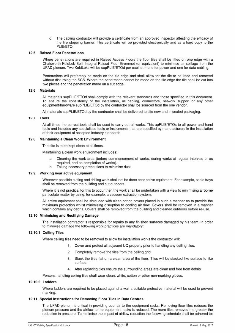
12.11 Special Instructions for Removing Floor Tiles in Data Centres
The UFAD plenum is critical in providing cool air to the equipment racks. Removing floor tiles reduces the plenum pressure and the airflow to the equipment racks is reduced. The more tiles removed the greater the reduction in pressure. To minimise the impact of airflow reduction the following schedule shall be adhered to:

UQ ICT Cabling Specification v2.2.docx Page 19 Printed: 2 May, 2017
Number of tiles removed
Maximum duration of removal per period
Period
1 - 4 6 hours 8 hours 5 - 10 1 hour 2 hours 10 - 20 20 minutes 1 hour > 20 Not allowed
Floor tiles are not to be left out of place overnight. A designated safety person is required to be adjacent to any removed tiles at all times or an appropriate barricade is to be used.
13. TELCOMMUNICATIONS RACKS
13.1 General
All racks will be black and, unless otherwise specified, 52 RU high.
The contractor will supply and assemble all racks including fitting of all shelves, PDUs, cable management, and fitting the cage nuts to every RU position on the front of the rack.
13.2 Cable management
All cabinets and racks will have a minimum 200mm vertical cable management area on both sides.
13.3 Racks
UQ’s preference is for the RT and Panduit line of products. Sample BoM’s are given in Annex B.
Unless otherwise specified the rack supPLIE/ETOd shall be a Type 3.
Open frame lab racks will be fixed to the floor as strongly as possible (eg: dynabolts, chemsets, etc). The top of the rack will be fixed to the ceiling or wall using 50mm unistrut extended at least 150mm down the channel of the frame from the top of the rack. Sample BoMs are given in Annex B.
13.4 Power
There are three options for power for Telecommunications Racks. The type to be used will be specified on a case by case basis. If nothing is specified then the 32A option will be installed.
The options are:
15A Option
For each rack the cabling contractor will install two 15A single phase, captive outlets comprising:
Qty Description Part Number 2 Clipsal 15A 250V 1 gang 3 pin combination surface switched socket outlet 56C315 GY
For each rack the cabling contractor will supply the following items:
Qty Description Part Number 2 APC Rack PDU, Metered, 1U, 16A, 208/230V, (8) C13 AP7821 2 Power Leads (Clipsal 56P315 to IEC-320-C19) @ 3m
2 Power Leads (IEC-320-C19 to IEC-320-C20) @ 2m
2 Power Leads (IEC-320-C19 to IEC-320-C20) @ 3m
12 Power Leads (IEC-320-C15 to IEC-320-C14) @ 2m
4 Power Leads (IEC-320-C15 to IEC-320-C14) @ 1m (1.2m is acceptable)
32A Option
For each rack the cabling contractor will install two 32A single phase, captive outlets comprising:
Qty Description Part Number 2 Clipsal Combination Switched Socket Enclosure 56E2 GY 2 Clipsal 32A 250V 1 gang surface rotary switch 56SW132LE GY 2 Clipsal 32A 250V 1 gang 3 pin surface socket outlets 56SO332/6LE GY
For each rack the cabling contractor will supply the following items:
Qty Description Part Number 2 APC Rack PDU, Metered, 2U, 32A, 230V, (12) C13 & (4) C19 AP7822 8 Power Leads (IEC-320-C19 to IEC-320-C20) @ 2m
2 Power Leads (IEC-320-C19 to IEC-320-C20) @ 1m (1.2m is acceptable)

UQ ICT Cabling Specification v2.2.docx Page 20 Printed: 2 May, 2017
12 Power Leads (IEC-320-C15 to IEC-320-C14) @ 2m
4 Power Leads (IEC-320-C15 to IEC-320-C14) @ 1m (1.2m is acceptable)
11kW Option
For each rack the cabling contractor will install two 20A three phase, captive outlets comprising:
Qty Description Part Number 2 Clipsal Combination Switched Socket Enclosure 56E2 GY
2 Clipsal 20A 500V 1 gang TP surface rotary switch 56SW320LE GY 2 Clipsal IEC 309 Socket 56S0516/6LE GY
OR
Qty Description Part Number 2 QIXING Interlock Socket with Switch QX5603
For each rack the cabling contractor will supply the following items:
Qty Description Part Number 2 APC Rack PDU 2G, Metered, ZeroU, 11kW, 230V, (36) C13 & (6) C19 AP8881 8 Power Leads (IEC-320-C19 to IEC-320-C20) @ 2m
2 Power Leads (IEC-320-C19 to IEC-320-C20) @ 3m 2 Power Leads (IEC-320-C15 to IEC-320-C14) @ 2m
2 Power Leads (IEC-320-C15 to IEC-320-C14) @ 1m (1.2m is acceptable)
The outlets will be installed at the same height above the finished floor as the highest point of the cabinet/rack.
One of the pair of power outlets will be on general power and the other on UPS. Where UPS is not available one of the outlets will be on the essential circuit.
Each outlet will be on a dedicated circuit breaker in the power distribution board.
14. ADMINISTRATION
14.1 Labelling
14.1.1 General
Unless otherwise specified the cabling contractor will supply all of the labelling detailed below.
All fixed cables shall be labelled at each end (behind the patch panel or TO) with self-laminating wrap around labels. Labels shall be affixed approximately 20mm from the stripped end of the cable sheath and shall comprise C-LOO (as per information below).
All cabinets and racks shall be labelled.
All patch panels shall be labelled.
Hand written labels will not be accepted.
14.1.2 Telecommunications Outlets
All TO’s shall be labelled.
All TO labels shall be 7mm Arial black text on a white background (9-12mm tape) and clearly legible from 1.8m.
TO labels shall be in the following format:
SS-BBBB-NNnnnn-CC-LOO where:
Description
SS Site designator
BBBB Building designator
NNnnnn Telecommunications Room Number
C Cabinet / Rack where terminated
L Letter assigned to patch panel
OO Outlet position number

UQ ICT Cabling Specification v2.2.docx Page 21 Printed: 2 May, 2017
The NNnnnn component can be variable length. The two uppercase NN indicates a minimum of 2 alphanumeric characters. The four lowercase nnnn indicates a maximum length of 6 alphanumeric characters.
The SSS-BB-NNnnnn-C portion of the address needs to be done only once per faceplate or MUTOA.
Example:
Outlets 7 and 8 on the patch panel labelled D of Cabinet A in TR number 203. The outlet is in Building 1 (Forgan Smith) at St Lucia.
More examples are shown in Annex A.
14.1.3 48 Port Patch Panels
All 48 port in 1RU patch panels will follow the numbering scheme shown below:
14.1.4 Order of Labelling
Outlet numbering will start from the corner of the building closest to North West and shall be done in a clockwise direction.
Within each room of a building the first outlet will be to the left of the lowest numbered door and shall be done in a clockwise direction.

UQ ICT Cabling Specification v2.2.docx Page 22 Printed: 2 May, 2017
Outlets will be done in pairs with the lowest numbered outlet being the odd number and on the left of the faceplate. Numbers shall always be sequential. Examples:
Allowed:
Not allowed:
Where the use of a single outlet or a triple outlet will disrupt this sequence then the next number is to be skipped. For example; a single outlet is installed for a CCTV camera and is labelled M13. M14 is only to be used for another single outlet or it must be skipped altogether. In this example it is permitted for the M13 and M14 not to be ordered in a clockwise direction.
14.1.5 Patch Panels
Patch panels will be labelled with a LETTER. Labels will comprise 10mm Arial white text on a black background on 12mm tape. Two labels will be affixed to each patch panel, one on the left hand edge and one on the right hand edge.
Patch panels will be labelled with letters as shown in Annex C. For example a patch panel in the 15th RU of a 42RU rack will be labelled “E”. A patch panel in the 22nd RU of a 52 RU rack will be labelled “P”. This is predicated on the RU numbering for the rack starting with 1 at the bottom and numbering upwards. Where the rack does not follow this convention (from the manufacturer) the contractor will ignore the manufacturer’s labels and assume 1 is at the bottom.
Inter rack patch panels will be labelled with the NNnnnn-C-L detail of the far end TR/cabinet/rack. If going to another cabinet in the same room it will be labelled with C-L only. Labels on patch panels will be white text on a black background (unless otherwise specified).
Examples of patch panel labels are shown in Annex A.
14.1.6 Consolidation Points
Consolidation points will be labelled on the outside with CP-FF-CC-L where:
CP – designates this as a consolidation point
FF-CC-L will be the same as for a TO.
The label will be 9mm black text on a white background (12mm tape).
The CP shall be labelled with the cable length from the TR.
The Tera hardware will be labelled the same as an inter rack patch panel.
14.1.7 Racks
All racks will be labelled front and rear with a flexible magnetic strip label. This will be 50mm high and 400mm long comprising white text on a matte black background. The text shall be 35mm high and 5mm thick and all in uppercase. The label will be placed on the highest point of the cabinet/rack from which it can be easily read.
The label will show the word “RACK” followed by a letter.

UQ ICT Cabling Specification v2.2.docx Page 23 Printed: 2 May, 2017
14.1.8 Power Distribution Units
Every PDU will be labelled front and rear with a flexible magnetic rubber strip label. This will be 30mm high and 35mm wide comprising white text on a black background. The label shall have a matt finish. The text shall be 10mm high and 1.5mm thick and all in uppercase. The label will be placed on the highest point of the PDU from which it can be easily read. If the label will not magnetically adhere to the PDU it shall be glued using four small dots of cyanoacrylate adhesive (superglue) apPLIE/ETOd in such a manner that the label will not fall off inadvertently but may be removed using a small amount of force.
The label will show the descriptor “DB” followed by the Distribution Board designator. The second line will show the descriptor “CB” followed by the Circuit Breaker number.
14.1.9 Optical Fibre Backbone Cables
All fibre optic cables shall be labelled in every telecommunications riser, pit entry, exit of any conduit and shall be labelled within 1m of entry to the FOBOT. All labelling exposed to the environment shall be punched stainless steel.
Any exposed or above ground conduits that have copper or Fibre optic telecommunications cable inside must have a firmly affixed label on the outside of the conduit at a maximum of 5 metre intervals. Fibre cables traversing building risers will be labelled at least once in each riser at 1200mm AFF. The label on the conduit must match the cable that is inside the conduit reflecting the standard labelling method outlined in this document.
All fibre cable installed in pits will have a minimum of two labels affixed showing the fibre cable’s unique identifying number. Labels WILL NOT show the A and B end building names or numbers.
14.2 Documentation
The following documentation shall be provided and updated to reflect changes:
a) Hand-over manual (soft copy and printed copy) providing information in accordance with the maintenance of a vendor certified installation.
b) The documentation shall include:
• Materials and equipment used. • Marked up (as built) documentation. • Performance Test Results. • SCS warranty and certification.
c) Electronic documentation shall be in the following formats:
• Floor plan – MS Visio • Rack Layout – MS Visio • Cable Schedule – MS Excel • Other – (Microsoft as required, e.g. power point)
14.3 As-Built Diagrams
UN has a very specific layout for as-built diagrams. A brief outline is given here:
• Format will be Microsoft Visio • UN will provide the base building drawing

UQ ICT Cabling Specification v2.2.docx Page 24 Printed: 2 May, 2017
• The contractor will mark up the drawing (outlets, WAPs, cable tray, access panels, etc) • Visio layer information will be STRICTLY adhered to.
The contractor may have an obligation to provide as-builts to the Principal Contractor in AutoCAD format. This UN requirement does not release you from that obligation. UN will work with the contractor to achieve the outcome that is required. An example of the layout is shown below:
15. TESTING
15.1 General
100% of cables will be tested.
Tests that report PASS* (marginal/star), FAIL* (marginal/star) or FAIL shall not be accepted.
15.2 Test Equipment
Only test equipment approved by the SCS vendor and correctly calibrated shall be used.
Test equipment shall only be used with the manufacturer’s approved accessory cables provided for testing of permanent link models.
15.3 Test Environment
Tests should be done in an environment as close to operational conditions as possible.
Cabling infrastructure shall not be moved after testing has taken place unless it is subsequently retested.
Testing shall be undertaken after workstation or adjacent power has been commissioned and whilst the office lighting is functioning.
15.4 Test Results
Test result sheets will include:

UQ ICT Cabling Specification v2.2.docx Page 25 Printed: 2 May, 2017
a. Test equipment used (make/model).
b. Operator’s name
c. Operators certification from test equipment vendor
d. Software / firmware revisions used during the testing
e. Date of calibration
f. A copy of a current manufacturer’s or National Australian Testing Association (NATA)
calibration certificate for all test equipment to be used, prior to the commencement of
testing.
Test results will be provided in Linkware format for xTP and LSPM, and Bellcore Telcordia Format for OTDR
LSPM results for optical fibre cable will be provided as one Linkware file per fibre cable. The file name will be in the format “SS-XXX.flw” where SS is the Site Designator (as per 14.1.2) and XXX is the fibre number.
15.5 Independent Third Party Test Result Verification
UQ deems the Structured Cabling System (SCS) supporting the network to be critical for its effective operation. In the interests of ensuring compliance to the performance requirements of the installed cabling system against Australian Standards and UQ requirements, the Contractor shall carry out all tests required to establish conformance. This apPLIE/ETOs to all installations irrespective of the communication contractor or structured cabling system vendor. For installations of more than 50 outlets it is a UQ requirement that all test data associated with structured cabling be independently verified by a NATA Type A Inspection Body. This requirement apPLIE/ETOs to both twisted pair and optical fibre test data. The contractor shall submit all SCS test results to UQ Approved NATA Inspection Body once the project is near completion. The cost of test verification shall be borne by the installation company and should be included in any quoted price or tender response. Costs may include fees for resubmission of data to address non-conformance issues. The Contractor shall pay for all expenditures incurred by UQ for re-inspection due to the Contractor’s failure to complete the SCS installation after the date of practical completion. No site will achieve practical completion until a “NATA Statement of Compliance” and associated NATA report has been received by UQ for all work forming part of the project. It is a UQ requirement that a copy of all NATA reports will be sent directly from the Approved NATA Inspection Body to UQ on generation.
15.5.1 Approved NATA Inspection Bodies
The Approved NATA Inspection Body shall be
• NATA accredited for inspections and that the scope of accreditation includes AS/NZS3080, similar standards and requirements set out within this specification.
• A NATA Type A Inspection Body and shall be independent from any equipment or Service provider. • Approval is based, in part, on the following
o NATA Scope of Accreditation including review of in-field testing results of LAN and telecommunications cabling covering optical fibre and copper cabling systems (balance pair systems)
o Ability to carry out High Level Analysis o Active participation in performance based communication cabling standards (Australian
Standards) o Active participation in testing standards of communication cabling (Australian Standards) o Active industry involvement o Quality of reporting.
UQ Approved Inspection Bodies:
VTI Services (Inspection Body NATA Accreditation Number 15120) 16 Banbury Crescent Chipping Norton NSW 2170 Australia +61-2-98242412 [email protected]

UQ ICT Cabling Specification v2.2.docx Page 26 Printed: 2 May, 2017
15.5.2 Analysis to be done by Independent Third Party for optical fibre test results
Fibre results – LSPM Fibre test results – OTDR – Full Analysis, including:
• Signature traces (two wavelengths, two directions) • Launch and Tail cables • First mated connector and last mated connector optical attenuation • Suitability for ORL of interface connectors and embedded events • Events along cable • Length comparison to LSPM
15.5.3 General Information
1. Signature trace analysis is carried out when compliance of the installation has first been established by Light Source and Power Meter testing.
2. Signature trace testing provides a graphical representation of the installed cabling and identifies individual embedded events within the links or channels in the direction tested.
3. The requirements for signature traces are not defined by Published National Standards but are invoked as part of contractual arrangements.
4. ORL requirements for mated connectors are specified within Published National Standards 5. Optical fibre traces taken at time of installation are often used for comparison over the life of the cabling
system. 6. Signature trace assessment is used to identify anomalies within Optical Links or channels. 7. OTDR traces that indicate anomalies may erode the value of the optical fibre system. These anomalies
could include; a. Length variation between LSPM and OTDR testing. b. Additional connectors and or splices contained within the link or channel c. Damage, repairs, or stress on the cable. d. Splices or mated connector events indicates high losses e. Contamination on fibre ends f. Continuity and polarity mismatch g. Validity of test data
8. Some anomalies are a result of testing methodologies and do not reflect the true status of the installed cabling, however, it is impossible to confirm the status of an installed cable when these anomalies exist.
15.5.4 Criteria for compliance
Assessment criteria for compliance for a signature trace includes the following
1. Correct Launch and Tail cables have been used 2. Mated connector reflectance does not exceed -35dB for single-mode installations and -20dB for multimode
installation 3. Mated connector loss does not exceed 1.5 dB 4. Accurate optical attenuation from OTDR traces requires the averaging of bidirectional test results. Optical
attenuation of a mated connector of 1.5dB is unlikely to be offset by a reading of suitable magnitude when tested in the opposite direction.
5. Range used for OTDR testing shall not exceed more than fifty percent of the length of the launch, tail and cable under test
6. Additional embedded events: a. Embedded splices within a link or channel do not exceed 0.6dB b. Embedded events along the cable do not exceed 0.2dB loss. Events of 0.05dB or greater can be
as a result of damage, stress or repairs to a fibre c. No additional embedded connectors within a link or channel. Reflective events with reflectance
more than -60dB and optical attenuation more than 0.05dB will be deemed as an embedded connector for the purposes of assessment of this report
7. Testing has been carried out at appropriate wavelengths 8. Test data provided is suitable and capable for establishing the status of all events along the cable 9. The dead zone of all reflective events shall not exceed 15m 10. Pulse width shall not exceed 40ns 11. Testing has been carried out at two appropriate wavelengths.

UQ ICT Cabling Specification v2.2.docx Page 27 Printed: 2 May, 2017
15.5.5 Criteria for Conditional Compliance
Assessment criteria for conditional compliance for a signature trace includes the following
1. Mated connector loss exceeds 0.75dB but not 1.5dB 2. Embedded events along the cable indicate apparent gains exceeding 0.1dB or losses exceeding 0.1dB but
not exceeding 0.2dB a. Events of 0.1dB can be as a result of damage, stress or repairs to a cable. b. Non reflective events of greater than 0.1dB may indicate a fusion splice
3. Embedded splices within a link or channel exceeding 0.3 dB but does not exceed 0.6dB. 4. The reporting of ghosts between the two end connectors of the Link or Channel
a. Ghosts are false indicators of reflective events like incorrectly mated connectors. b. Ghosts have no optical attenuation (Loss)
Please Note:
o Empirical values of events were ascertained by OTDR Software event tables. o Readings outside of expectations are deemed to be caused by anomalies within the test equipment
(including cords), test configuration, OTDR setup and/or user error. o Signature trace assessment covers the cable under test and five (5) metres of any test cable from the
connection of the cable under test. o Assessment of this limited portion of the test cord is to enable anomalies that may impact the validity of
the test data.
15.6 Minimum Test Standards
As a minimum the following parameters shall be tested and recorded.
15.6.1 Class D, E, EA, F and FA Links
All test results shall be reported using the Permanent Link model.
Compliance testing for Class EA requires a level 3e or level 4 tester as defined by AS/NZS ISO/IEC 61935.1. Class E requires a level 3 tester. If uncertain, the contractor is to consult the cabling vendor about approved testers before starting the installation.
Electrical acceptance tests shall be carried out on all xTP cables in accordance with AS/NZS IEC 61935.1 in accordance with values set out in AS/NZS 3080 (ISO/IEC 11801). Test equipment must be calibrated and calibration certificates must be supPLIE/ETOd. Accredited installers must also be trained and certified for the test equipment used for acceptance testing. Certificates must be provided.
15.6.2 Voice Grade links
a. Pair continuity/rotation
b. Date of test
15.6.3 Fibre Optic links
Compliance testing for MMOF and SMOF shall be in accordance with AS/NZS ISO/IEC 14763.3 and AS/NZS 3080 (ISO/IEC 11801).
Accredited installers must be trained and certified for the test equipment used for acceptance testing. Certificates of competence must be provided.
Test equipment must be calibrated and calibration certificates must be provided.
The following information will be provided:
a. UQ Fibre Cable Number
b. Date of test
c. Length in metres
d. Insertion loss measured at 1310nm and 1550nm in both directions with a
Light Source/Power Meter.
e. OTDR traces (as per below).
LSPM Test results will be provided electronically in the testers’ native format along with VTI Services fibre reporting sheet completed (www.vti.net.au)

UQ ICT Cabling Specification v2.2.docx Page 28 Printed: 2 May, 2017
All fibre cores over shall be tested with an OTDR utilising a launch and a tail cable in both directions and at both wavelengths
All OTDR testing shall be presented in a Bellcore format
No mated connectors are to have an optical attenuation loss exceeding 0.75dB-Analysis by two point LSA method on the OTDR trace
No event other than a mated connector shall have a loss greater than 0.2dB. - Analysis by two point LSA method on an OTDR trace
The pass fail criteria will be that specified within AS/NZS ISO/IEC 14763.3.
Launch and tail cable associated with OTDR testing shall be of sufficient length to determine the optical return loss of the interface connectors of the link under test.
A loss budget shall be provided for each fibre run. An electronic copy of all test results shall be submitted and included in the As Built documentation.
The One Test Reference Cord (TRC) method will be used for testing all fibre links.
16. COMMISSIONING
16.1 As Built / As Installed Diagrams
UQ recognises that there is an inherent delay between PC and the provision of (CAD drawn) marked up floor plans showing outlet numbering and position. No later than 2 weeks before PC the contractor will provide a set of hand marked up floor plans showing outlet location and numbering. The hand mark ups must be legible.
16.2 Test Plan
A comprehensive test plan will be provided to the PLIE/ETO at least 2 months before PC. This will detail what tests will be undertaken and when.
16.3 Labelling
The site supervisor will personally confirm that all labelling is correct. If during the DLP any labelling is found to be incorrect then UQ will engage an independent third party (at UQs discretion) to conduct a full audit. The cost of this audit will be invoiced to the cabling contractor. The contractor will then remedy any defects.
16.4 Defect process
The contractor will provide a contact phone number and email address for logging defects with the SCS. Requests for rectification work will be attended to within 2 business days during the DLP.
16.5 Warranty
The contractor will provide a contact phone number and email address for logging warranty claims.
17. PROGRESS PAYMENTS
17.1 General
The following schedules will apply for progress payments.
17.2 Project value < $30k
One invoice will be paid on completion of the works. This will not be paid until test results and as-builts have been received.
17.3 Project value $30k - $300k
Materials delivered to site – 20%
Rough in completed – 30%
Installation completed – 40%
As-builts and test results received – 10%

UQ ICT Cabling Specification v2.2.docx Page 29 Printed: 2 May, 2017
17.4 Project value > $300k
Materials delivered to site – 20%
Tray installed – 10%
Rough in completed – 30%
Installation completed – 30%
As-builts and test results received – 10%
18. ANNEX A – LABELLING EXAMPLES
Example – 3 outlet faceplate
Outlets 11, 12 and 13 on the patch panel labelled H in Cabinet B in TR number 104. The outlet is in Building 8170A (Landscape Shed) at Gatton. Note: If the next faceplate is also a triple is can start at H14. If it is a double then H14 will be skipped (could be used for a single).
Example – 3 outlet vertical faceplate
Example – 24 port patch panel GOING TO TR 208, cabinet B, Patch Panel A.

UQ ICT Cabling Specification v2.2.docx Page 30 Printed: 2 May, 2017
Example – 24 port patch panel going via a CP.

UQ ICT Cabling Specification v2.2.docx Page 31 Printed: 2 May, 2017
19. ANNEX B – CABINET / RACK OPTIONS
19.1 Type 1
For Telecommunications Room with 1 x Panduit 52RU Lab Rack:
Bill of Materials
Qty Description Part Number 1 Panduit 52RU four post rack, numbered up, cage nut, 23" deep R4P23CN96 1 Panduit 1RU Minder NM1 1 Panduit 2RU Minder NM2 2 Panduit Vertical Minder – 9ft tall, 12" wide PEV1296 2 Panduit Vertical Minder Front Doors PED1296 2 Panduit 23" Adjustable Shelf RSHLF23 4 Pack 100 Cage Nuts and Screws. 1 B&R Cable Hanger BRQ-Q10600A/3 1 Nylex Safe-T-Step (or equivalent) E739A 1 Bailey Ladder - FG Platform Step 3 (150kg) FS10721 1 Bailey Castor Kit (to be fitted by contractor) FS23120
19.2 Type 2
For Telecommunications Room with 1 x Rack Technologies 52RU – Lab Rack:
Bill of Materials
Qty Description Part Number 1 Rack Technologies IQ Open Frame 52RU IQOF5201 1 Rack Technologies IQ 1RU Horiz CM 150mm Finger System IQOF9509-150 1 Rack Technologies IQ 2RU Horiz CM 150mm Finger System IQOF9502-150 4 Rack Technologies IQO-F Cable Manager 300W Long Fingers IQOF5240-150 As rq’d
Rack Technologies IQO-F Cable Manager 400W Long Fingers IQOF5250-150
1 Rack Technologies Shelf S-SHELF-MOD-300-BL 4 Rack Technologies pack 100 Cage Nuts and Screws. 9075 1 B&R Cable Hanger BRQ-Q10600A/3 1 Nylex Safe-T-Step (or equivalent) E739A 1 Bailey Ladder - FG Platform Step 3 (150kg) FS10721 1 Bailey Castor Kit (to be fitted by contractor) FS23120
19.3 Type 3
For Telecommunications Room with 1 x Rack Technologies 52RU – 4 post open frame cabinet:
Bill of Materials
Qty Description Part Number 2 Rack Technologies IQ Open Frame 52RU IQOF5201 1 Rack Technologies IQ 1RU Horiz CM 150mm Finger System IQOF9509-150 1 Rack Technologies IQ 2RU Horiz CM 150mm Finger System IQOF9502-150 4 Rack Technologies IQO-F Cable Manager 300W Long Fingers IQOF5240-150 As rq’d
Rack Technologies IQO-F Cable Manager 400W Long Fingers IQOF5250-150
1 Rack Technologies Shelf S-SHELF-MOD-300-BL 1 Rack Technologies IQ Open Frame Joining Kit Adjustable (400-600mm) IQOF9514 4 Rack Technologies pack 100 Cage Nuts and Screws. 9075 1 B&R Cable Hanger BRQ-Q10600A/3 1 Nylex Safe-T-Step (or equivalent) E739A 1 Bailey Ladder - FG Platform Step 3 (150kg) FS10721 1 Bailey Castor Kit (to be fitted by contractor) FS23120
19.4 Type 4
For Telecommunications Room with 1 x Rack Technologies 45RU – 4 post open frame cabinet:
Bill of Materials
Qty Description Part Number 2 Rack Technologies IQ Open Frame 45RU IQOF4501 1 Rack Technologies IQ 1RU Horiz CM 150mm Finger System IQOF9509-150 1 Rack Technologies IQ 2RU Horiz CM 150mm Finger System IQOF9502-150 4 Rack Technologies IQO-F Cable Manager 300W Long Fingers IQOF4540-150 1 Rack Technologies Shelf S-SHELF-MOD-300-BL 1 Rack Technologies IQ Open Frame Joining Kit Adjustable (400-600mm) IQOF9514

UQ ICT Cabling Specification v2.2.docx Page 32 Printed: 2 May, 2017
4 Rack Technologies pack 100 Cage Nuts and Screws. 9075 1 B&R Cable Hanger BRQ-Q10600A/3 1 Nylex Safe-T-Step (or equivalent) E739A 1 Bailey Ladder - FG Platform Step 3 (150kg) FS10721 1 Bailey Castor Kit (to be fitted by contractor) FS23120
19.5 Type 5
For Telecommunications Room with 2 x 52RU – Rack Technologies 4 post open frame cabinet:
Bill of Materials
Qty Description Part Number 4 Rack Technologies IQ Open Frame 52RU IQOF5201 2 Rack Technologies IQ 1RU Horiz CM 150mm Finger System IQOF9509-150 2 Rack Technologies IQ 2RU Horiz CM 150mm Finger System IQOF9502-150 4 Rack Technologies IQO-F Cable Manager 300W Long Fingers IQOF5240-150 2 Rack Technologies IQO-F Cable Manager 400W Long Fingers IQOF5250-150 2 Rack Technologies Shelf S-SHELF-MOD-300-BL 2 Rack Technologies IQ Open Frame Joining Kit Adjustable (400-600mm) IQOF9514 2 Rack Technologies pack 100 Cage Nuts and Screws. 9075 1 B&R Cable Hanger BRQ-Q10600A/3 1 Nylex Safe-T-Step (or equivalent) E739A 1 Bailey Ladder - FG Platform Step 3 (150kg) FS10721 1 Bailey Castor Kit (to be fitted by contractor) FS23120

UQ ICT Cabling Specification v2.2.docx Page 33 Printed: 2 May, 2017
20. ANNEX C – TYPICAL RACK ELEVATIONS
21. ANNEX D – APPLICATION EXAMPLES (FOR PLIE/ETO)
21.1 NEW BUILDING
All facets and specifications described in this document will apply.
21.2 MAJOR REFURBISHMENT OF A BUILDING
All facets and specifications described in this document will apply.
21.3 REFURBISHMENT OF A SINGLE FLOOR IN A BUILDING
An assessment will need to be made of the current SCS. It may be appropriate to re-use the SCS. If the current SCS is Category 4 or 5 (not 5e) the entire SCS on the floor being refurbished would need to be replaced.

UQ ICT Cabling Specification v2.2.docx Page 34 Printed: 2 May, 2017
21.4 ADDING ADDITIONAL OUTLETS TO AN EXISTING SCS
As a rough guide anything less than 24 outlets can be done at a standard homogenous to the installed SCS except where the current SCS is Category 4 or 5 (not 5e). In this case the new outlets could be done as a minimum of Class E (Cat 6).
If more than 24 outlets are required then there would need to be compelling reasons not to install Class EA cables. Examples of valid reasons are:
a. inadequate cable minders,
b. inadequate pathways and spaces to cater for larger bend radius and larger physical cable,
etc
Cost is not a valid reason for non-compliance.

UQ ICT Cabling Specification v2.2.docx Page 35 Printed: 2 May, 2017
22. ANNEX E – TELECOMMUNICATIONS ROOM EXAMPLES

UQ ICT Cabling Specification v2.2.docx Page 36 Printed: 2 May, 2017
23. ANNEX F – QGEA COMPLIANCE
23.1 General
UQ is bound by Queensland Government State Purchasing Policy and is obligated to comply with the Queensland Government Enterprise Architecture (QGEA), ICT Cabling Technical Standard.
Of particular note in this standard:
Paragraph 3.3 – …the procurement of ICT cabling infrastructure shall be undertaken separately from other building works, including the Electrical works.
Paragraph 4.2 – The minimum warranty provided by the manufacturer of the infrastructure connecting hardware shall be 20 years full parts and labour warranty for the cable and connecting hardware and 20 years applications assurance (or protocol assurance) warranty.
Paragraph 4.3 – Single System Sites
Paragraph 4.4 - Multiple System Sites
A copy of the standard is available from:
http://www.qgcio.qld.gov.au/images/documents/QGEA_documents/QGEA/ICTcablinginfrastructurestandardv300.pdf (copy and paste link into your browser).
23.2 Single System Sites
23.2.1 St Lucia, Gatton, Indooroopilly Mine, and Pinjarra Hills.
A TE Connectivity solution will be used (Tyco Electronics, ADC Krone, and AMP Netconnect).
Typical parts list:
(under development)
23.2.2 Royal Brisbane and Women’s Hospital, Herston.
A MOLEX solution will be used.
Typical parts list:
(under development)
23.3 Multiple System Sites
23.3.1 Princess Alexandra Hospital.
• PACE building - A TE Connectivity solution will be used (Tyco Electronics, ADC Krone, and AMP Netconnect).
• TRI building - A Siemon solution will be used.
23.3.2 Other Queensland Health Sites.
Where the buildings are owned and managed by QH, the QH Cabling Specification will apply.
23.3.3 Other UQ Sites.
UQ will assess these on a case by case basis.
24. ANNEX R – REVISION HISTORY DETAIL
2.2 2. Updated abbreviations list. 7.3 Updated contact information. 11.2 Added floor and wall finishes. 13.4. No RCD on 32 A option removed. 15.5.4. Changed pulse width max. 19.3 Added 400W minders. 15.6.3 Removed testing for MMOF. Annex E changed intermediate minders to 400mm wide.
2.1 Changed all references to UTP to xTP. Removed references to CT Racks and CT Rack BoM. Added requirement for fire stopping to comply with NCC requirements. Added no RCDs on 32A circuits (13.4). Changed OTDR to both directions (15.6.3). Added prox readers, A/C, GM2 keys, and Sound Pressure levels (11.2). Added clarification to running cables for 48 port patch panels (12.1.3). Updated Typical Rack Elevation (Annex C). Updated Panduit BoM (19.1 Rack Type 1). 6.3 clarified all OF test results to be independently verified

UQ ICT Cabling Specification v2.2.docx Page 37 Printed: 2 May, 2017
2.0 Added patch panel density to summary (6.6). Added 48 port default patch panel to 12.1.3 (c). Changed 24 cables to 48 cables in 12.1.3 (f). Added requirement for Traffic Management Plan to 10.5. Modified Quareo table 12.2.4. Highlighted removal and installation of WAPs in Summary (6.10). Added 48 patch panel labelling (14.1.3)
1.3 updated link to QGCIO in para 23.1. Added 12.2.4 regarding FOBOTS. Changed 11.3.4 to specify Milliken Smart Path. Added QGEA to table in 8.1. Added 3rd party test requirements (15.5). Added GPN3 Room 110 (12.2.4).
1.2 added door height to 11.2. added 12.2.1 (i) – high density FOBOT faceplates. 12.2.1 (c) added transition to tight buffered.13.4 changed IEC leads from C13/C14 to C15/C14 (high temp). Added 608 to provide emphasis to 7.1 (p). Added para in 15.4 to get fibre results in separate files. Added 12.1.3 (e) and photo.
1.1 Section19.6 Added CT 52RU BoM. Changed 13.3 to specify either RT or CT 52 RU as default
1.0 Removed C-I-C header. Removed “DRAFT” watermark. Updated grammar and spelling.
0.7 Added section on power options (13.4) and removed power from cabinet BoM’s (Annex B). Updated labelling (14.1.2). Changed all general references to cabinets and racks to -> racks only (remove cabinet). Added Jayan contact details. Added progress payments schedule (17).
0.6 Clarified pit and pipe section.
0.5 Amended labelling from RU numbering to Letter. Tightened up fibre testing section. Changed testing method to 1 TRC.
0.4 Rewrote Work Health & Safety section on advice from George Nicholls
0.3 Added sample cabinet BoM. Added Annex F – QGEA compliance
0.2 Removed requirement to label all UTP leads
0.1 First draft