upt project _study of radar system
TRANSCRIPT

BHARAT ELECTRONICS LIMITED
PROJECT REPORT
SUBMITTED BY: Veer Vaibhav Singh
ROLL NO: A2305110095
College:Amity School of Engineering and Technology

CONTENTS
1 : CERTIFICATE2 : ACKNOWLEDGEMENT3 : PREFACE4 : BHARAT ELECTRONICS INDUSTRY5 : B E: SALES ANS SERVICES6 : FORMATION OF UNIT7 : PROJECT: STUDY OF RADAR SYSTEM
TO WHOM SO EVER IT MAY CONCERN
I certify that Veer Vaibhav Singh, has joined BEL, Ghaziabad for six-weeks industrial training w.e.f. 15.05.2013 to 29.06.2013 and he has been constantly working under my guidance on the project assigned to him.
He has worked on the project STUDY OF RADAR SYSTEM. His contribution was in testing of Rohini Radar and its subsystems.
This report accounts his experience and knowledge of the field he worked in. I have verified the report and sanction it.
Signature Signature Project Guide Project Head

ACKNOWLEDGEMENTI take this opportunity to express my sincere gratitude towards Mr.R.N Tyagi (Manager., HRD), Bharat Electronics, Ghaziabad for accepting my letter and
allowing me to complete my training in Bharat Electronics.
I am extremely grateful to Mr. S.S. Chaturvedi, (Sr. DGM, RADAR Department) Bharat Electronics, for permitting me to join PAR-2 Department.
Further I would like to thank Mr S.R. Naqvi, Mr. S.P. Vishvakarma, Ms. Laxmi Chauhan and Ms.Aditi Mehta for their time to time guidance and help extended during each stage of our project.
Finally, I would like to thank each and every member of BEL family for making me feel comfortable and helping me in every possible manner.

PREFACEThe six month training is a part of our B.Tech, Electronics and Communication.
Practical Industrial Training mainly aims at making one aware of industrial environment; which means that one gets to know the limitation, constraint and freedom under which an engineer works. One also gets an opportunity to watch from close quarter that indicates manager relation. This training mainly involves industrial and complete knowledge about designing, assembling and manufacturing process of various equipments manufactured by an industry.
During this six month period, as a student, there is a great opportunity of understanding Industrial practices. Most of the theoretical knowledge that has been gained during our course is useful only if it can be applied to production and services in the industry. The learnt is applied, tested, verified and rectified. Apart from this the student gets an opportunity to learn latest technology and is upgraded of the new trends immersing in the industry of interest.
I had the opportunity to utilize my six month summer internship in BHARAT ELECTRONICS LIMITED, GHAZIABAD [U.P.]. I was a part of the company’s new venture CAR, which provided me a great deal of learning. My sphere of knowledge was expanded both at technical and personal level. I not only got chance to work on Live Project but also witnessed the related industrial processes and got acquainted to many of the prevalent technologies.

INTRODUCTION TO BEL

BHARAT ELECTRONICS LIMITEDINDUSTRY
Bharat Electronics Limited (BEL) was established in 1954 as a Public Sector Enterprise under the administrative control of Ministry of Defence as the fountain head to manufacture and supply electronics components and equipment. BEL, with a noteworthy history of pioneering achievements, has met the requirement of state-of-art professional electronic equipment for Defence, broadcasting, civil Defence and telecommunications as well as the component requirement of entertainment and medical X-ray industry. Over the years, BEL has grown to a multi-product, multi-unit, and technology driven company with track record of a profit earning PSU.
The company has a unique position in India of having dealt with all the generations of electronic component and equipment. Having started with a HF receiver in collaboration with T-CSF of France, the company's equipment designs have had a long voyage through the hybrid, solid state discrete component to the state of art integrated circuit technology. In the component arena also, the company established its own electron valve manufacturing facility. It moved on to semiconductors with the manufacture of germanium and silicon devices and then to the manufacture of Integrated circuits. To keep in pace with the component and equipment technology, its manufacturing and product assurance facilities have also undergone sea change. The design groups have CADDs facility, the manufacturing has CNC machines and a Mass Manufacture Facility, and Quality Control (QC) checks are preformed with multi-dimensional profile measurement machines, Automatic testing machines, environmental labs to check extreme weather and other operational conditions. All these facilities have been established to meet the stringent requirements of MIL grade systems.
Today BEL's infrastructure is spread over nine locations with 29 production divisions having ISO-9001/9002 accreditation. Product mix of the company is spread over the entire Electro-magnetic (EM) spectrum ranging from tiny audio frequency semiconductor to huge radar systems and X-ray tubes on the upper edge of the spectrum. Its manufacturing units have special focus towards the product ranges like Defence Communication, Radar's, Optical & Opto-electronics, Telecommunications, Sound and Vision Broadcasting, Electronic Components, etc.
Besides manufacturing and supply of a wide variety of products, BEL offers a variety of services like Telecom and Radar Systems Consultancy, Contract Manufacturing, Calibration of Test & Measuring Instruments, etc. At the moment, the company is installing MSSR radar at important airports under the modernization of airports plan of National Airport Authority (NAA).
BEL has nurtured and built a strong in-house R&D base by absorbing technologies from more than 50 leading companies worldwide and DRDO Labs for a wide range of products. A team of more than 800 engineers is working in R&D. Each unit has its own R&D Division to bring out new products to the production lines. Central Research
Laboratory (CRL) at Bangalore and Ghaziabad works as independent agency to undertake contemporary design work on state-of-art and futuristic technologies. About 70% of BEL's products are of in-house design.
BEL was among the first Indian companies to manufacture computer parts and peripherals under arrangement with International Computers India Limited (ICIL) in 1970s. BEL assembled a limited number of 1901 systems under the arrangement with ICIL. However, following Government's decision to restrict the computer manufacture to ECIL, BEL could not progress in its computer manufacturing plans. As many of its equipment were microprocessor based, the company continued to develop computers based application, both hardware and software. Most of its software requirements are in real time. EMCCA, software intensive naval ships control and command system is probably one of the first projects of its nature in India and Asia.
BEL has won a number of national and international awards for Import Substitution, Productivity, Quality, Safety Standardization etc. BEL was ranked no.1 in the field of Electronics and 46th overall among the top 1000 private and public sector undertakings in India by the Business Standard in its special supplement "The BS 1000 (1997-98)". BEL was listed 3rd among the Mini Ratanas (category II) by the Government of India, 49th
among Asia's top 100 Electronic Companies by the Electronic Business Asia and within the top 100 worldwide Defence Companies by the Defence News, USA.
BEL has production units established at different parts of the country. The year of establishment and location are as follows:
Serial no.
Year of establishment
Location
1.
2.
3.
4.
5.
6.
7.
8.
9.
1954
1972
1979
1979
1984
1984
1985
19851986
Bangalore
Ghaziabad
Pune
Taloja (Maharashtra)
Hyderabad
Panchkula (Haryana)
Chennai
Machhilipathnam (A.P.)Kotdwara (U.P.)

Motto Mission and Objectives
The passionate pursuit of excellence at BEL is reflected in a reputation with its customers that can be described in its motto, mission and objectives:
Manufacturing Units
Bangalore (Karnataka)
CORPORATE MOTTO
"Quality, Technology and Innovation."CORPORATE MISSION
To be the market leader in Defence Electronics and in other chosen fields and products.
CORPORATE OBJECTIVES To become a customer-driven company supplying quality products at
competitive prices at the expected time and providing excellent customer support.
To achieve growth in the operations commensurate with the growth of professional electronics industry in the country.
To generate internal resources for financing the investments required for modernization, expansion and growth for ensuring a fair return to the investor.
In order to meet the nation's strategic needs, to strive for self-reliance by indigenization of materials and components.
To retain the technological leadership of the company in Defence and other chosen fields of electronics through in-house Research and development as well as through Collaboration/Co-operation with Defence/National Research Laboratories, International Companies, Universities and Academic Institutions.
To progressively increase overseas sales of its products and services.
To create an organizational culture which encourages members of the organization to realize their full potential through continuous learning on the job and through other HRD initiatives?
BEL started its production activities in Bangalore in 1954 with 400W high frequency (HF) transmitter and communication receiver for the Army. Since then, the Bangalore Complex has grown to specialize in communication and Radar/Sonar Systems for the Army, Navy and Air Force. BEL's in-house R&D and successful tie-ups with foreign Defence companies and Indian Defence Laboratories has seen the development and production of over 300 products in Bangalore alone. The Unit has now diversified into manufacturing of electronic products for the civilian customers such as D.O.T., V.S.N.L., A.I.R. and Doordarshan, Meteorological Dept., I.S.R.O., Police, Civil Aviation, and Railways. As an aid to Electorate, the unit has developed Electronic Voting Machines that are produced at its Mass Manufacturing Facility (MMF).
Ghaziabad (Uttar Pradesh)
The second largest Unit at Ghaziabad was set up in 1974 to manufacture special types of radar for the Air Defence Ground Environment Systems (Plan ADGES). The Unit provides Communication Systems to the Defence Forces and Microwave Communication Links to the various departments of the State and Central Govt. and other users. The Unit's product range included Static and Mobile Radar, Tropo scatter equipment, professional grade Antennae and Microwave components.
Pune (Maharashtra)
This Unit was started in 1979 to manufacture Image Converter Tubes. Subsequently, Magnesium Manganese-dioxide Batteries, Lithium Sulphur Batteries and X-ray Tubes/Cables were added to the product range. At the present the Unit manufactures Laser Sub-unit for tank fire control systems and Laser Range Finders for the Defence services.
Machilipatnam (Andhra Pradesh)
The Andhra Scientific Co. at Machilipatnam, manufacturing optics/Opto-electronic equipment was integrated with BEL in 1983. The product line includes Passive Night Vision Equipment, Binoculars, Binoculars and Goggles, Periscopes, Gun Sights, Surgical Microscope and Optical Sights and Mussle Reference Systems for tank fire control systems. The Unit has successfully diversified to making the Surgical Microscope with zoom facilities.
To cater the growing needs of Defence Communications, this Unit was established in 1985. Professional grade Radio-communication Equipment in VHF and UHF ranges entirely developed by BEL and required by the Defence services are being met from this Unit.
Chennai (Tamil Nadu)
In 1985, BEL established another Unit at Chennai to facilitate manufacture of Gun Control Equipment required for the integration and installation in the Vijayanta

tanks. The Unit is now manufacturing Stabilizer Systems for T-72 tanks, Infantry Combat Vehicles BMP-II; Commander's Panoramic Sights & Tank Laser Sights are among others.
Kotdwar (Uttar Pradesh)
In 1986, BEL started a Unit at Kotdwara to manufacture Telecommunication Equipment for both Defence and civilian
Customers Focus is being given on the requirement of the Department of Telecommunications to manufacture Transmission and Switching Equipment.
Taloja (Maharashtra)
For the manufacture of B/W TV Glass bulbs, this plant was established in collaboration with coming, France in 1986. The Unit is now fully mobilized to manufacture 20" glass bulbs indigenously.
Hyderabad (Andhra Pradesh)
To coordinate with the major Defence R&D Laboratories located in Hyderabad, DLRL, DRDL and DMRL, BEL established a unit at Hyderabad in 1986. Force Multiplier Systems are manufactured here for the Defence services.

Joint Ventures
BE-Delft Electronics Limited
BE-Delft Electronics Limited, Pune, the first joint venture of the company with Delft Instruments, Holland and UTI was established in the year 1990 for conducting research, development and manufacture of Image Intensifier Tubes and associated high voltage power supplies for use in military, security and commercial systems. Its products include night vision goggles and binoculars, night vision weapon sights and low light level input applications.
GE BE Private Limited
GE BE Private Limited, Bangalore, a JV with General Electric Medical Systems, USA has been established in 1997-98 for manufacture of High End Rotating Anode Medical Diagnostic X-ray tube called CT MAX, which is used in CT Scanners. The joint venture unit will also establish a reloading facility for X-ray tubes and will also market the conventional X-ray tubes made at Pune Unit of BEL. South East Asia markets are addressed by this joint venture.
BEL- Multitone Private Limited
A joint venture between Bharat Electronics and Multitone Electronics Plc, UK has also been established in Bangalore in 1997-98 to manufacture state-of-art Mobile Communication for the workplace. Multitone invented paging in 1956 when it developed the world's first system to serve the "life or death" environment of St. Thomas Hospital, London. With the strength of Bharat Electronics in the Radio Communications field and the technology of Multitone, in the field of Radio Paging, the joint venture company is in a position to offer tailor made solution to the Mobile Communication needs at workplace in various market segments.
Customer Profile & BEL Product Range

Equipment
Equipment
Components
DefenceArmy Tactical and Strategic Communication Equipment and
Systems, Secrecy Equipment, Digital Switches, Battlefield Surveillance Radar, Air Defence and Fire Control Radar, Opto-Electronic Instruments, Tank Fire Control Systems, Stabilizer Systems, Stimulators and Trainers.
Navy Navigational, Surveillance, Fire Control Radar, IFF, SONAR Systems, Torpedo Decoys, Display Systems, EW Systems, Simulators, Communication Equipment and Systems.
Air Force Surveillance and Tracking Raiders, Communication Equipment and Systems, IFF and EW Systems.
Non-DefencePara-Military Communication Equipment and Systems.Space Department Precision Tracking Radar, Ground Electronics, Flight and
On-Board Sub-systems.All India Radio MW, SW & FM Transmitters.Doordarshan(TV Network)
Low, Medium and High Power Transmitters, Studio Equipment, OB Vans, Cameras, Antennae, Mobile and Transportable Satellite Uplinks.
NCERT TV Studios on Turnkey Basis for Educational Programs.Department ofTelecommunications
Transmission Equipment (Microwave and UHF) and PCM Multiplex, Rural and Main Automatic Exchanges, Flyaway Satellite Terminals, Solar Panels for Rural Exchanges.
Videsh SancharNigam and otherCorporate Bodies
MCPC VSAT, SCPC VSAT, Flyaway Earth Stations. Hub Stations, Up/Down Converters, LNA Modems
Civil Aviation Airport Surveillance Radar, Secondary Surveillance Radar.Meteorological Department
Cyclone Warning and Multipurpose Meteorological Radar.
Power Sector Satellite Communication Equipment.Oil Industry Communication Systems, Radar.Forest Departments,Irrigation &Electricity Boards
Communication Systems.
Medical &Health Care
Clinical and Surgical Microscope with Zoom, Linear Accelerators.
Railways Communication Equipment for Metros, Microwave Radio Relays, And Digital Microwave Radio Relays.

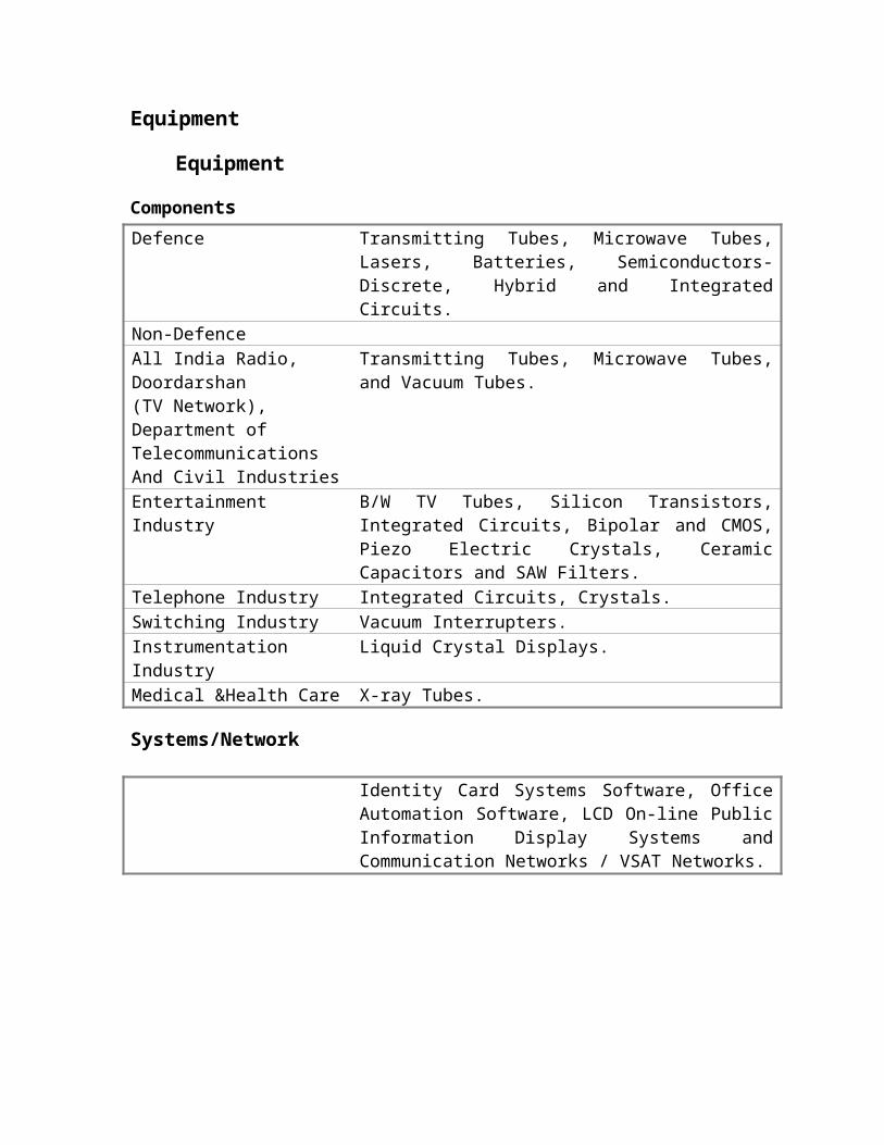
Defence Transmitting Tubes, Microwave Tubes, Lasers, Batteries, Semiconductors-Discrete, Hybrid and Integrated Circuits.
Non-DefenceAll India Radio,Doordarshan(TV Network),Department of TelecommunicationsAnd Civil Industries
Transmitting Tubes, Microwave Tubes, and Vacuum Tubes.
EntertainmentIndustry
B/W TV Tubes, Silicon Transistors, Integrated Circuits, Bipolar and CMOS, Piezo Electric Crystals, Ceramic Capacitors and SAW Filters.
Telephone Industry Integrated Circuits, Crystals.Switching Industry Vacuum Interrupters.Instrumentation Industry Liquid Crystal Displays.Medical &Health Care X-ray Tubes.
Systems/Network
Identity Card Systems Software, Office Automation Software, LCD On-line Public Information Display Systems and Communication Networks / VSAT Networks.
Financial Performance
BEL has a unique history of profit making Public Sector Enterprise right from its inception. There have been events of decrease in turnover and profit after Tax due to reasons beyond reasonable control of the company. But the company's strength lies in its capability to combat the threats, for example US Embargo on exports to BEL.
BEL hopes to generate 25 per cent increase in turnover with a 15 per cent rise in net profit in the current fiscal year over the previous. Corrective measures against western sanctions have been undertaken, which are likely to translate into higher turnover and profitability. The company is putting all efforts to minimize the effect of the restrictions by early establishments of alternative arrangements. The Defence Research Laboratories and Academic Institutions are also being persuaded with for indigenization of certain special category of devices and components. The company is also opening an office in Singapore to procure components from Asian markets. Thus in the long run the restrictions will prove as blessings resulting in self-dependence and better profit margins.
Also several R&D projects with long gestation periods will go into commercial production during the current fiscal.

Product Range
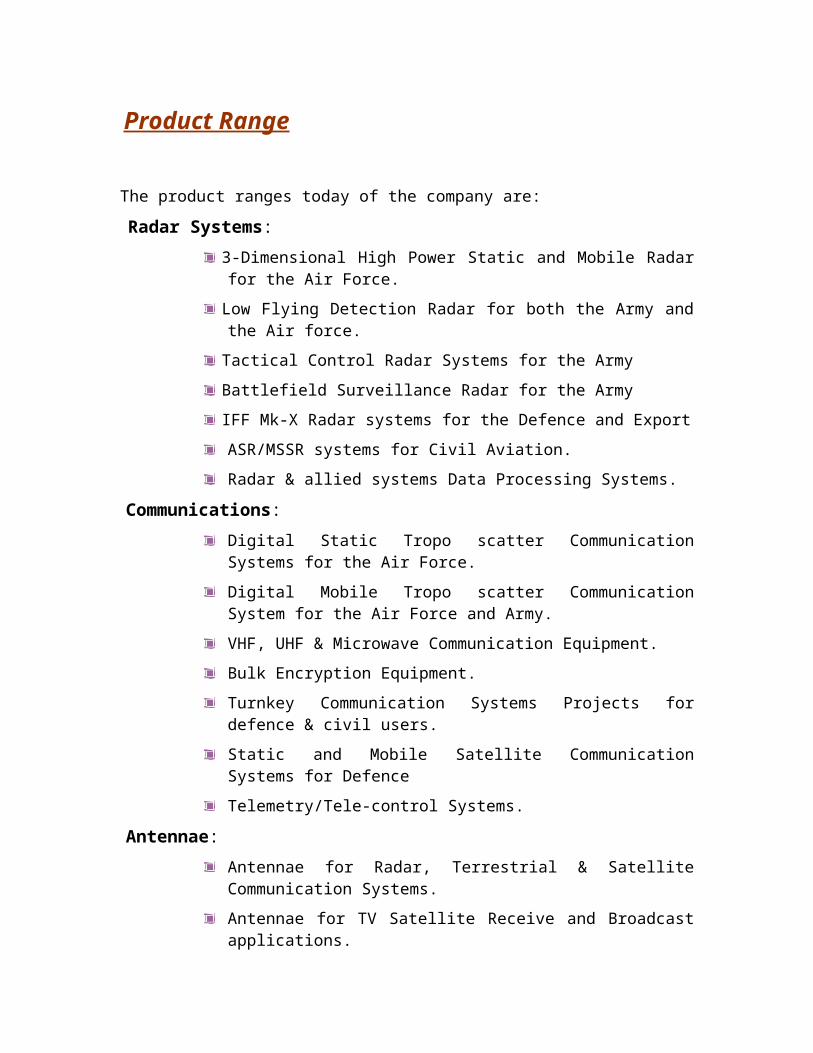
The product ranges today of the company are:
Radar Systems:3-Dimensional High Power Static and Mobile Radar for the Air Force.
Low Flying Detection Radar for both the Army and the Air force.
Tactical Control Radar Systems for the Army
Battlefield Surveillance Radar for the Army
IFF Mk-X Radar systems for the Defence and Export
ASR/MSSR systems for Civil Aviation.
Radar & allied systems Data Processing Systems.
Communications:Digital Static Tropo scatter Communication Systems for the Air Force.
Digital Mobile Tropo scatter Communication System for the Air Force and Army.
VHF, UHF & Microwave Communication Equipment.
Bulk Encryption Equipment.
Turnkey Communication Systems Projects for defence & civil users.
Static and Mobile Satellite Communication Systems for Defence
Telemetry/Tele-control Systems.
Antennae:Antennae for Radar, Terrestrial & Satellite Communication Systems.
Antennae for TV Satellite Receive and Broadcast applications.
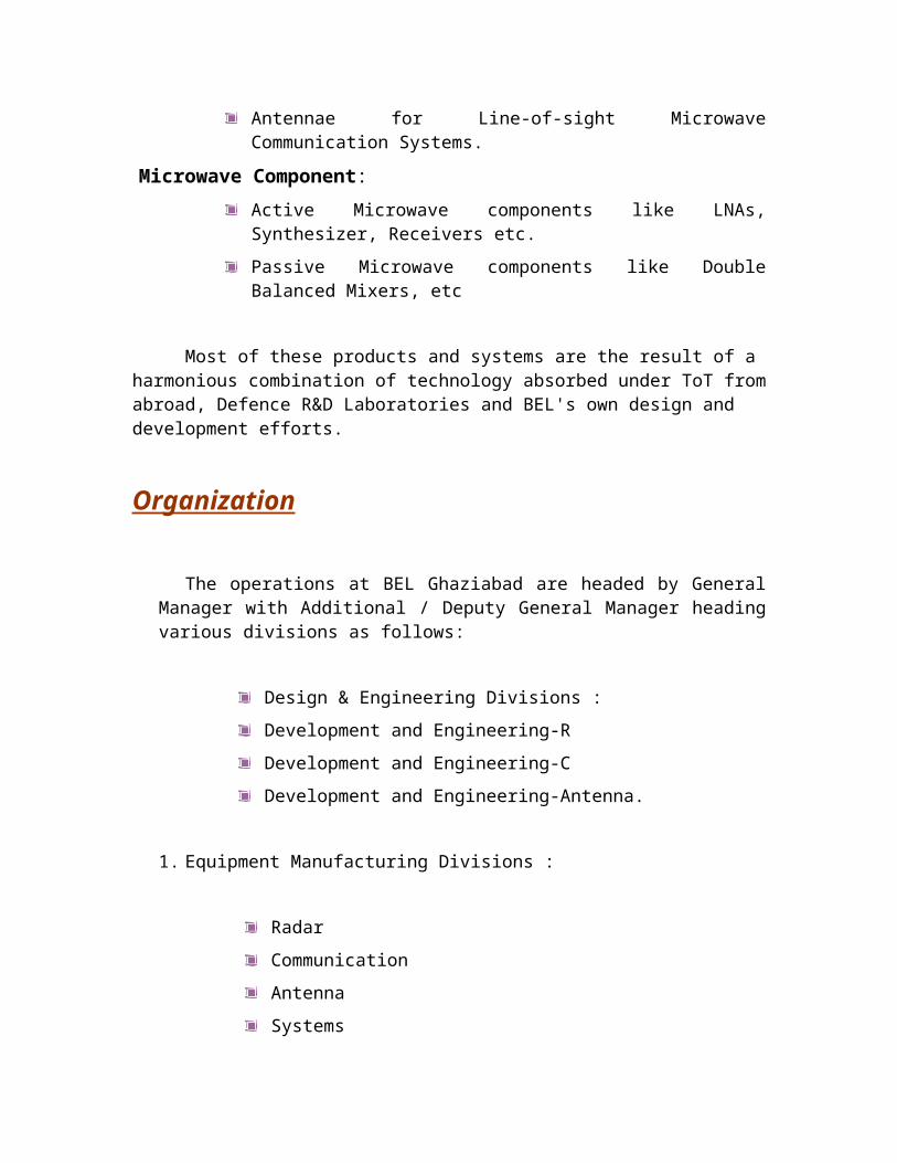
Antennae for Line-of-sight Microwave Communication Systems.
Microwave Component:Active Microwave components like LNAs, Synthesizer, Receivers etc.
Passive Microwave components like Double Balanced Mixers, etc
Most of these products and systems are the result of a harmonious combination of technology absorbed under ToT from abroad, Defence R&D Laboratories and BEL's own design and development efforts.

Organization
The operations at BEL Ghaziabad are headed by General Manager with Additional / Deputy General Manager heading various divisions as follows:
Design & Engineering Divisions :
Development and Engineering-R
Development and Engineering-C
Development and Engineering-Antenna.
1. Equipment Manufacturing Divisions :
Radar
Communication
Antenna
Systems
Microwave Components.
2. Support Divisions:
Material Management
Marketing & Customer Co-ordination
Quality Assurance & Torque
Central Services
PCB & Magnetics
Information Systems
Finance & Accounts
Personnel & Administration
Management Services.

Design & Engineering:The pace of development and technological obsolescence in their field of
electronics necessitates a strong Research and Development base. This is all the more
important in the area of Defence Electronics. BEL Ghaziabad has since its inception laid a heavy emphasis on indigenous research and development. About 70% of its manufacture today relate to items developed in-house. For the development and production of the Mobile Tropo scatter System and the IFF equipment, BEL was awarded the Gold Shield for Import Substitution.
Design facilities are also constantly being modernized and substantial computer-aided design facilities are being introduced including installation of mini- and micro-computers and dedicated design application. About 170 graduate and post-graduate engineers are working on research and development and indication of the importance R&D has in BEL's growth.
Three Design and Engineering groups are product based viz. Communication, Radar and Antenna. These divisions are further divided into different departments to look after products of a particular nature. Each of them has a drawing office attached to them, which are equipped with latest drafting and engineering software. The PCB layout and PCB master making is done at CADDs Center. A central Records & Printing section takes care of the preserving the engineering documents and distribution thereof. Most of the engineering documents are available online.
Equipment Manufacturing Divisions: As a supplier of equipment to the Defence services and professional user, strict
adherence to specifications and tolerances has to be in-built into the design and manufacturing process. For this BEL Ghaziabad has well defined standards and processes for as well as manufacturing and testing activities. Activities are divided into various departments like Production Control, Works Assembly, and QC WORKS. The manufacture and control of production is through a central system, BELMAC, BEL's own homegrown ERP system.
Apart from conventional machines, BEL Ghaziabad has been equipped with several Computer Numerical Control (CNC) machines for ensuring repeat occurrences and increased throughput. A separate NC programming cell has been set up to develop the programs for execution on the CNC machines.
Microwave Component Group:Frequencies greater than 1 GHz is termed as Microwaves. Microwaves Integrated
Circuits (MIC) used extensively in the production of subsystems for Radar and Communication equipment constitutes a very vital part of the technology for these systems and is generally imported. Owing to the crucial and building block nature of the technology involved, BEL is currently setting up a modern MIC manufacturing facility at a planned expenditure of Rs. 2 crore. When in full operation, this facility will be the main center for the MIC requirements of all the units of the company.
The manufacturing facilities of hybrid microwave components available at BEL, Ghaziabad includes facility for preparation of substrates, assembly of miniaturized
component viz. directional couplers, low noise amplifiers, phase shiftier, synthesizers etc. involves scalar as well as vector measurements. For this state of the network analysis are used.
Material Management:Material Management division is responsible for procurement, storage handling,
issue of purchased parts as well as raw materials required to manufacture various equipment and spares. It also takes care of disposal of unused or waste material.
The division is divided into Purchase, Component store, Raw material store, Chemical store, Inwards good store, Custom clearance Cell, Inventory management & disposal.
Marketing and Customer Co-ordination:This division is responsible for acquisition and execution of customer orders and
customer services. Marketing department looks after order acquisition. Commercial department looks after order execution. Shipping takes care of packing and dispatch of material to customer.
Quality Assurance & Torque:In the area of professional Defence electronics, the importance of Quality and
Reliability is of utmost importance. BEL has therefore established stringent processes and modern facilities and systems to ensure product quality- from the raw material to the finished product. IGQA, Environmental Labs, Test Equipment Support and QA departments are grouped under this division.
All material for consumption in the factory passes through stringent inward goods screening in IGQA department before being accepted for use.
Subsequent to manufacture and inspection, the end product is again put through a rigorous cycle of performance and environmental checks in Environmental Labs.
The testing, calibration and repair facility of test Instruments used in the factory is under the control of Test Equipment Support. All the instruments come to this department for periodic calibration.
Quality Assurance department facilitates ISO 9000 certification of various divisions. All production divisions of BEL Ghaziabad are ISO9000 certified. The microwave division is ISO9001 certified whereas the remaining three division viz. Radar, Communication and Antennae are also ISO9002 certified.
Central Services:Central services Division looks after plant and maintenance of the estate including
electrical distribution, captive power generation, telephones, transport etc.
PCB Fabrication & Magnetics:PCB Fabrication, Coil and Magnetics, Technical Literature, Printing Press and
Finished Goods are the areas under this division.

Single sided PCB blanks- having circuit pattern only on one side of the board and double sided - having circuit pattern on both sides of the board are manufactured in house. However, Multi-layered PCBs, having many layers of circuit, are obtained from other sources.
Magnetic department makes all types of transformers & coils that are used in different equipment. Coils and transformers are manufactured as per various specifications such as number of layers, number of turns, types of windings, gap in core, dielectric strength, insulation between layers, electrical parameters, impedance etc. laid down in the documents released by the D&E department.
Information Systems:IS Department is responsible for BEL's own home grown manufacturing and
control system called BELMAC. It comprises of almost all modules a modern ERP system but is Host and dumb terminal based.
Finance & Accounts:The F&A division is divided into Budget & Compilation, Cost and Material
Accounts, Bills Payable, Bill Receivable, Payrolls, Provident Fund, Cash Sections
Personnel & Administration: There are at present about 2300 employees at BEL Ghaziabad, of which more
than 400 are graduate and post graduate engineers.
P&A Division is divided into various departments like Recruitment, Establishment, HRD, Welfare, Industrial Relations, Security and MI Room.
Management Services:
This department deals with the flow of information to or from the company. It is broadly classified into three major sub-sections - Management Information System, Industrial engineering department and Safety.
Production Control
The main goals of the production control are:
To improve the profits of the company by better resource management
To ensure on-time delivery products
To improve the quality of product
To reduce the capital investment
To reduce working capital needs by better inventory management

Production control is responsible for producing the products, right from the stage engineering.
Drawings are received to the stage where it is store credited as finished product. It’s basic function is to identify the parts/operations to be made, the best way of making them, the time when they have to be made and to arrange the production resources to the optimum.
The commercial department obtains orders from equipments through quotations. The equipment stock order (ESO) is released by commercial department. Then the management services department issues work order for the quantity of equipment to be made. This is for the calculation for the cost of the project then D&E department develops the equipment and releases the following engineering documents:
KS : Key Sheet
PL : Part List
GA : General Assembly Diagram
CL : Connection List
WL : Wiring Diagram
Now the production control takes the responsibility of manufacturing the equipment. PC decides for items to be purchased from outside, for items to be manufactured by other companies and prepares documents for items to be made inside the company.
Documents issued by the PC:
I. Process sheet (fabrication): This process sheet indicates the process and the sequence of operation to be followed in various work cells and work centers. Every item is timed by productivity services.
II. Process sheet (Assembly): This is similar to PS (fabrication) except that it is used in electronics assembly, PCB assemblies, cable form and cable assemblies.
III.Process sheet (coils): This indicates operation analysis for transformer and coils.
IV. Schedule for RM, fasteners and PPs: This gives the gross requirements for raw materials, purchased parts, fasteners etc. Based on this material control department initiates procurement action and store requisitions are released with reference to this schedule.
Tool Planning
1. Some of the items while under fabrication require the use of some jigs and fixtures.
2. The cost estimation, revenue and budget plans are got approved by the board of management
3. Standard hour is approved by the department. This is the time, which is decided to complete the job by a worker in a stipulated time, which is decided on the previous records of the shop, type of machine used and the nature of work.
4. Report on production value is evaluated for each unit.
My Training in BEL, was attended in two phases. In first phase, I was given a schedule to visit all the departments in BEL, relevant to my field of Electronics and Communication. In this period of orientation, I visited different departments and was introduced to the current technology used and the various industrial processes under practice. In the second phase I was allotted a Project under Project Manager, Mr. S.S. Chaturvedi (CAR- RADAR).
I am briefing my experience and observation about various departments of the company in next paragraphs.
ROTATION
ABOUT VARIOUS DEPARTMENTS
MICROWAVE INTEGRATED CIRCUITSFrequencies greater than 1 GHz are termed as Microwaves. Microwave Integrated
Circuit used extensively in production of subsystems for Radar and Communication equipment constitutes a very important part of technology for these systems are generally imported. Owing to the crucial and building block nature of the technology involved, BEL is currently setting up a modern MIC manufacturing facility at a planned expenditure of Rs. 2 crore. When in full operation this facility will be the main center for the MIC requirements of all the units of the company.
The manufacturing facility of hybrid microwave components available at BEL Ghaziabad includes facility for preparation of substrates, assembly of miniaturized components on substrates, bonding and testing. Testing of these microwave components viz. Directional couplers, Waveguides, low noise amplifiers, phase shifters, synthesis etc. involve scalar as well as vector measurements. For this state of the network, analyses are used. Various losses such as return loss, bending loss, insertion loss are measured and testing is done in a way to minimize these losses.
MICROWAVE LAB
This section undertakes:
1. Manufacturing of films and microwave components to meet internal requirements.
2. Testing of low power antenna for which test-site is about 100 Km from the factory at sohna.
The main component testing in this department is:
Oscillators
Amplifiers
Mixers
Radiation elements (e.g. Feeders)
Microwave components (e.g. Isolators, circulators, waveguides etc.)
Filters (e.g. LPF, BPF, Uniplexers, and Multiplexers etc.)

Functioning of component is listed below:
Frequency response
Noise figure
VSWR
Directivity and coupling
Power measurements
Various instruments in the lab are:
Adaptor
Attenuator
Coupler
Mixer
Detector
ENVIRONMENTAL LABVarious tests conducted in the environmental lab in BEL in order to ensure
reliability. Reliability is defined as the probability of a device performing its purpose adequately for the period intended under the given operating conditions. In a given system reliability is given as
R = R1 * R2 * R3 ……
The standards available here are:
JSS 55555 - Joint Services Specifications (Military Standard of India)
Mil Standards - U.S. Military standards
QM333 - Civil Aviation and Police
TYPES OF TESTS
1. FIRST ARTICLE TEST (FAT)These tests are performed on the prototype. If these tests are successful then the mass
production is taken up.

The tests are:1. Vibration Test System2. High Temperature Operate and Storage3. Low Temperature Operate and Storage4. Damp Heat Operate and Storage5. Altitude Chamber6. Bump Test Machine7. Salt Fog Chamber8. Tropical Storage9. Mould Growth Chamber
VARIOUS TESTS IN DETAIL:
1. Vibration Test System The item is vibrated when kept over the plate of the machine. The frequency Range is 1 to 2,000 Hz. Radar PCB’s are vibrated at 10 to 50 Hz at 2g (g=9.8m/s2) for 15’.
2. Humidity chamber Used to test the product under varying humidity conditions. For Navy instruments conditions for humidity are 95% at +45C for 16 hours.
3. Cold Heat This chamber has a temperature of –90 to +180. This chamber program is controlled and has an accuracy of +0.5 and has a graph plotting system.
4. Mould GrowthThis chamber is used to test how immune the product is against mould growth.
5. Salt Spray It is used to check the resistivity of the item produced against salty water.
6. Climatic ChamberTemperature range of – 65C to +200C and relative humidity is from 20%
To 98%RH.
7. Walk – In Chamber
This is a big chamber of size 2.6m, 2.4m, 3m Temp. range of – 60C to +100C and the humidity is from 20% to 90% RH.
8. Bump Machine Item is dropped from a certain height every time it receives bump from Machine. Maximum capacity of the machine is 11.35 Kg. Drop height is Around 1 inch.

9. Altitude Chamber Used to test the item under different temperature and humidity conditions.
The temperature range for this chamber is from -40C to +150C and can create environmental conditions as per a height of 50,000 feet’s.
For airforce equipment the instrument is kept at a temperature of +40C for 30,000 ft and at 0C for 13,500 ft.
2. ACCEPTANCE TEST PROCEDURE
This sets on the extent to which a test is to be conducted and also decides what tests should be conducted.
There are three types of tests:
a) Class A test: This test includes visual and dimensional checks. All equipments of regular production go through these checks. These include quality control and electrical tests.
b) Class B test: These are quality assurance and reliability tests. Only 10% of equipments go through these tests. They include quality control, electrical tests and some environmental tests.
c) Class C test: These are carried out on 1% of the components. All the environmental tests are performed. If any failure is seen, the component must be redesigned. Also the customer must be supplied with modified goods. This test comes in picture for bulk production only.
FAILURE RATE GRAPH
Failure rate graph- It is the failure versus time graph.The infant morality is the critical period. It is due to:
Weak componentManufacturing defect
This is the area where the producer tries to cover in the warranty period.The repeated failures are detrimental to a company’s reputation as these are eliminated by screening while in manufacturing stage. The other screening is the stress screening method. This consists of:
a) HUMIDITY TEST: Humidity is created with the help of boilers and fans in the chamber. Required temperature and duration of the tests are selected as per the specified BEL standards.
b) ALTITUDE TEST: The conditions such as very low temperature (created with the help of cooling systems) and very low temperature and pressure (created with the help of a vacuum pump) are maintained in a chamber. These conditions are comparable to those at high altitudes where the products have to work.

c) AGEING AND THERMAL SHOCKS: One cycle of ageing is of 7 hours. Ageing is done to relieve the stresses developed in the PCB due to blazing, welding, riveting etc. The sample is first kept at ambient temperature (250 degree Celsius) and then cooled to -400 degree Celsius.
d) BUMP TEST: The sample is given bumps in one direction only, with the help of machine. The number of bumps to be given is set with the help of proper switches. The sample is operated after giving bumps. If it works properly, it is passed.
e) VIBRATION TEST:The sample is subjected to vibrations. Required frequency and amplitude for vibrations is selected accordingly.
f) SALT SPRAY TEST: Salt solution is sprayed in a chamber. The specimens are hanged in the chamber. The test helps to decide any corrosion that takes place due to spraying of solution.
g) RAIN TEST: In this test, conditions are created such that the sample is made to bath in heavy rain, so that if any problem arises in the sample due to rain that can be sorted accordingly.
h) DROP TEST : The sample is made to survive in such a environment where there is possibility of snow fall. Such conditions are created in a chamber, to sort out any problem arises due to this.
i) ROADABILITY TEST: While doing bump test, bumps are given to the sample in unidirectional only. But in the roadability test, bumps are given to the sample in all the directions. It means that the test is being carried, considering the device to be moving in a zigzag manner on an uneven road. For e.g. in sand or in water etc. This test helps to make out any fault or loosening of components while moving the specimen from one place to another.
j) BOMB TEST: This is a test conducted for special types of samples. In this the samples are exposed to a situation like a bomb blast and it is checked whether the sample is able to bear the bomb explosion.
WALK IN CHAMBER
A very huge used for conducting humidity and temperature tests. The size of the chamber is such that a person can easily walk into it. It is for large sized specimens.
PCB FABRICATION
PCB is abbreviated form of printed circuit board. As the name suggests, in a PCB the electrical circuit is printed on a glass epoxy board. This reduces the complex writing network whose trouble shooting in case of shorting or misconnection is not easy.PCB fabrication is mostly done for house requirements. It also takes some external jobs.
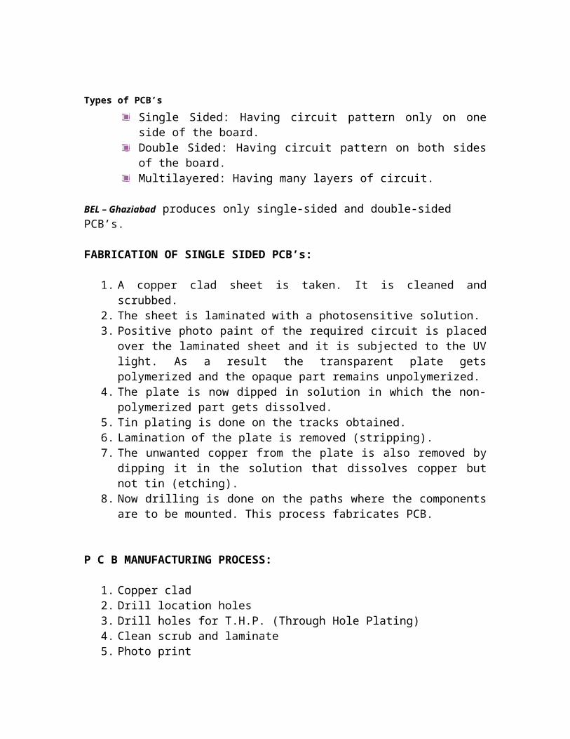
Types of PCB’s
Single Sided: Having circuit pattern only on one side of the board.Double Sided: Having circuit pattern on both sides of the board.Multilayered: Having many layers of circuit.

BEL – Ghaziabad produces only single-sided and double-sided PCB’s.
FABRICATION OF SINGLE SIDED PCB’s:
1. A copper clad sheet is taken. It is cleaned and scrubbed. 2. The sheet is laminated with a photosensitive solution. 3. Positive photo paint of the required circuit is placed over the laminated sheet and
it is subjected to the UV light. As a result the transparent plate gets polymerized and the opaque part remains unpolymerized.
4. The plate is now dipped in solution in which the non-polymerized part gets dissolved.
5. Tin plating is done on the tracks obtained.6. Lamination of the plate is removed (stripping). 7. The unwanted copper from the plate is also removed by dipping it in the solution
that dissolves copper but not tin (etching). 8. Now drilling is done on the paths where the components are to be mounted. This
process fabricates PCB.
P C B MANUFACTURING PROCESS:
1. Copper clad2. Drill location holes3. Drill holes for T.H.P. (Through Hole Plating)4. Clean scrub and laminate5. Photo print6. Develop7. Copper electroplate8. Tin electroplate9. Strip film10. Etch and clean11. Strip tin12. L.P.I.S.M. (Liquid Photo Imageable Solder Mask)13. Photo print14. Develop15. Thermal baking16. Hot air level17. Legend marking/Reverse marking18. Route and clean
But these PCB’s have the following disadvantages:
Due to very narrow spacing between adjacent tracks, there may be a chance of short circuit if the soldering is done by hands between the components on opposite side.

Moisture or dust between the gaps may disrupt smooth soldering.
These disadvantages are overcome by soldered mask PCB’s. in the later one an additional film is put on the earlier fabricated PCB, leaving points where components are to be soldered.
TEST EQUIPMENT & AUTOMATION
TEST EQUIPMENT SUPPORT (TES) Main functions are:
Develops technical support to other departments.Repair of equipment in case of failure.Maintenance of equipments.Periodic calibration of equipments.Provide technical support to other departments. This includes:
1. Handling requests from the other department for equipments.2. Storage of rejected equipments.3. Approval of equipments to be purchased.
This section deals with testing and the calibration of electronic equipments only the standards of this department are calibrated by National Physics Laboratory (NPL).
AUTOMATION TEST EQUIPMENT (ATE)
1. Component testing gives faults of various discrete components of a PCB.2. Integrated circuits tester tests various IC’s. 3. Functional testing compares output to decide whether the function is being
performed to the desired level of accuracy.
WORKS ASSEMBLY
This department plays an important role in the production. Its main function is to assemble various components, equipment’s and instruments in a particular procedure. It has two sections, namely:
1. PCB assembly2. Electronic assembly

In PCB assembly, the different types of PCB are assembled as per BEL standards. PCB is received from the PCB department on which soldering of component is done either by hand soldering or wave soldering.
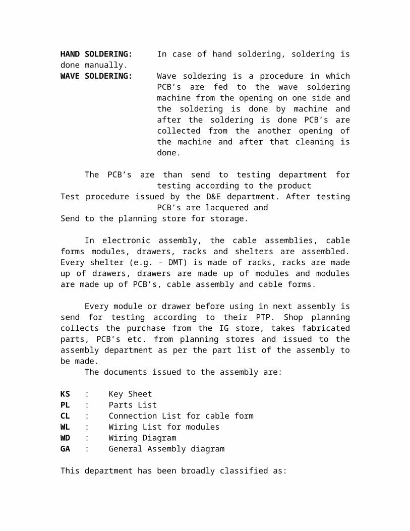
HAND SOLDERING: In case of hand soldering, soldering is done manually.WAVE SOLDERING: Wave soldering is a procedure in which PCB’s are fed to
the wave soldering machine from the opening on one side and the soldering is done by machine and after the soldering is done PCB’s are collected from the another opening of the machine and after that cleaning is done.
The PCB’s are than send to testing department for testing according to the product Test procedure issued by the D&E department. After testing PCB’s are lacquered and Send to the planning store for storage.
In electronic assembly, the cable assemblies, cable forms modules, drawers, racks and shelters are assembled. Every shelter (e.g. - DMT) is made of racks, racks are made up of drawers, drawers are made up of modules and modules are made up of PCB’s, cable assembly and cable forms.
Every module or drawer before using in next assembly is send for testing according to their PTP. Shop planning collects the purchase from the IG store, takes fabricated parts, PCB’s etc. from planning stores and issued to the assembly department as per the part list of the assembly to be made.
The documents issued to the assembly are:
KS : Key SheetPL : Parts ListCL : Connection List for cable formWL : Wiring List for modulesWD : Wiring DiagramGA : General Assembly diagram
This department has been broadly classified as:
1. WORK ASSEMBLY RADAR e.g. : INDRA-2 , REPORTER ,CAR2. WORK ASSEMBLY COMMUNICATION e.g. : EMC CA , MSSR , MFC
EMCCA: EQUIPMENT MODULAR FOR COMMAND CONTROL APPLICATION
MSSR: MONOPULSE SECONDARY SURVEILLANCE RADAR
MFC: MULTI FUNCTIONAL CONSOLE
The stepwise process followed by work assembly department is:

1) Preparation of part list that is to be assembled.2) Preparation of general assembly.3) Schematic diagram to depict all connection to be made and brief idea about all
components.4) Writing list of all components.
METHOD OF P C B PROCESSING
1. Tinning2. Preparation3. Mounting4. Wave soldering5. Touch up6. Quality control7. Ageing8. Testing9. lacquering (AV)10. Storing
SURFACE MOUNTING TECHNOLOGY
The works assembly has a totally computerized section of PCB assembling of SMD (Surface Mounting Device). In this section the operation of PCB assembling is totally controlled by computers. The various steps taken in computer PCB assembling of SMD’s are as follows:
1. Application of solder paste: Solder paste is applied onto the places on PCB where the SMD’s are to be soldered. This is done by computer controlled machine. The program is loaded in the machine; it reads the program and applies the solder paste at the required place.
2. Fixture of SMD’s:a) The SMD’s are fixed at the right place on PCB by another computer
controlled machine. b) The components (SMD) are first fed to various feeder lines that are
attached to the machine and the related software and program is loaded in computer.
c) There is a provision for a camera also so that we can monitor the entire operation.
d) The PCB is then fed to the machine. e) When the appropriate command is given to the computer, it initiates
the machine attached to itf) The machine picks the correct SMD from the feeder line and fix it at
the right place on the PCB and within seconds all SMD’s are fixed on the PCB.
3. Thermal Baking: After the fixture of SMD’s, thermal baking is done. In this the PCB is fed to the oven and after 10 to 20 minutes PCB is taken out.
NOTE: Surface Mounting Device (SMD) does not require any hole on PCB as they are mounted directly on the PCB. The pins of SMD components are called ’legs’ as they have leg like structure unlike simple components that have straight pins that are soldered in the holes on the PCB manually.
SHOP ORDER
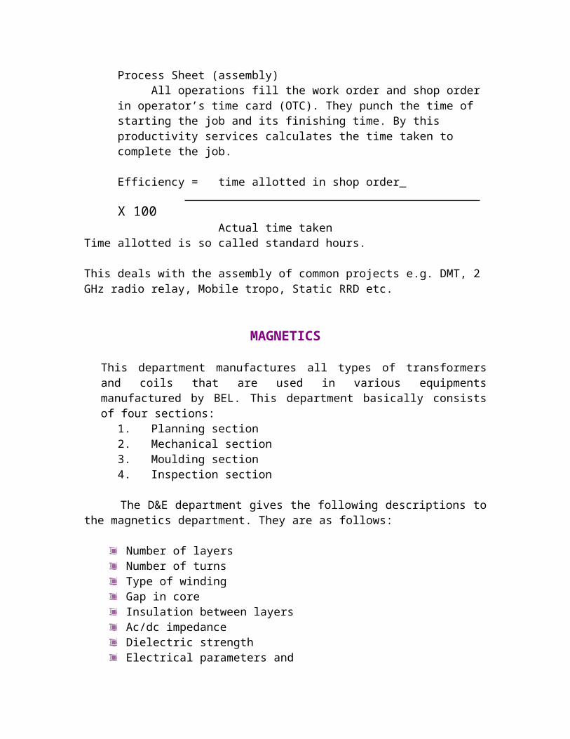
Process Sheet (assembly)All operations fill the work order and shop order in operator’s time card
(OTC). They punch the time of starting the job and its finishing time. By this productivity services calculates the time taken to complete the job.
Efficiency = time allotted in shop order X 100
Actual time takenTime allotted is so called standard hours.
This deals with the assembly of common projects e.g. DMT, 2 GHz radio relay, Mobile tropo, Static RRD etc.
MAGNETICS
This department manufactures all types of transformers and coils that are used in various equipments manufactured by BEL. This department basically consists of four sections:
1. Planning section2. Mechanical section3. Moulding section4. Inspection section
The D&E department gives the following descriptions to the magnetics department. They are as follows:
Number of layersNumber of turnsType of windingGap in coreInsulation between layersAc/dc impedanceDielectric strengthElectrical parameters andEarthing
The various transformers being made are:
Open type transformerOil cooling type transformerMoulding type transformerPCB moulding type transformer
The transformer is mechanically assembled, leads are taken out and checking of specification is done.
Winding machines are of three types:
Heavier ones- DNR for 0.1 to 0.4 mm diameterLC controlled machinesTorroidal machines having 32 operations from winding to mechanical assembly.
The various types of windings used are:
Hand windingTorroidal windingSector windingPitch windingVariable pitch windingWave winding
Two main types of core used are:
E-type for 3-phaseC-type for single phase
Following procedure involved in the manufacture of the transformer is as follows:
1. Formers of glass epoxy2. Winding3. Core winding4. Varnishing5. Impregnation – In this process various varnished coils are heated, then
cooled, reheated and put into vacuum. Then air is blown to remove the humidity.
6. Moulding – Araldite (a certain type of strong glue) mixed with black dye is used to increase mechanical as well as electrical strength. Moulding is done at 120 degree Celsius for 12 hours.A RDB compound is used for leakage protection. Oil is then boiled at 70 to 80 degree Celsius under vacuum condition to remove air bubbles trapped
inside during manufacturing process. After this the coils are dipped in varnish and core is attached.
7. Painting8. Mechanical assembly9. Termination10. Stenciling11. Testing – Dielectric testing (both ac/dc) is done at 50 KV voltage
is applied for a minimum of one minute. During inspection, the following characteristics are checked:
a. Turns ratiob. DC resistance for each coilc. Inductanced. No load voltagee. Leakage
This section the material used for making transformer is Bakelite comprising a male and female plates which are joined alternately to form a hollow rectangular box on which winding is done. Winding is done with different material and thickness of wire. The winding has specified number of layers with each layer having a specified number of turns. The distance between the two turns should be maintained constantly that is there should be no overlapping. The plastic layer is inserted between two consecutive layers.
Types of Windings:1) Layer Winding2) Wave Winding3) Bank Winding
Different types of windings are done to control some parameters such as inductance and capacitance. Varying the spacing between the two turns can vary these parameters. Two consecutive turns act as capacitor. As gap between the turns increases the capacitance decreases and inductance increases. Since capacitance is inversely proportional to the gap between the plates of capacitor and inductance is directly proportional. After winding the core is inserted between the primary and secondary. Contact leads are taken out and molding is done for maximum heat dissipation. Rubber solution is used to give strength to the wires, so that they cannot break. This is done before molding. Varnishing is done as anti fungus prevention for against environmental hazard. After compilation of manufacturing process it is sent for testing. Different parameters such as inductance, capacitance efficiency, turns ration, continuity are tested.
QUALITY CONTROL WORKS
According to some laid down standards, the quality control department ensures the quality of the product.
The raw materials and components etc. purchased are inspected according to the specifications by the IG department. Similarly QC works department inspects all the items manufactured in the factory.
The fabrication inspection checks all the fabricated parts and ensures that these are made as per the part drawing. Plating, Painting and stenciling etc are done and checked as per the BEL standards.
The assembly inspection department inspects all the assembled parts such as PCB, cable assembly, cable form, modules, racks and shelters as per latest documents and BEL standards.
The mistakes in the PCB can be categorized as:
D&E mistakeShop mistakeInspection mistake
A process card is attached to each PCB under inspection. Any error in the PCB is entered into the process card by certain codes specified for each error or defect.
After mistake is detected, following actions are taken:
Observation is made.Object code is given.Division code is given.Change code is prepared.Recommended action is taken.
RADAR ASSEMBLY
This deals with the assembly of RADARS, e.g. INDRA-I, INDRA-II, FLY CATCHER, EMMCA, IRMA, REPORTER, CAR etc.
The main projects under construction are:
CAR
In RADAR section RADAR being tested is REPORTER, FLY CATCHER, EMCCA, etc.
PROJECT
PROJECT : STUDY OF RADAR SYSTEM
BASIC PRINCIPLE OF RADARA radar operates by radiating electromagnetic energy and detecting the echo returned from reflecting objects (targets). The nature of the echo signal provides information about the target. The range, or distance, to the target is found from the time it takes for the radiated energy to travel to the target and back. The angular location of the target is found with a directive antenna (one with a narrow beamwidth) to sense the angle of arrival of the echo signal. If the target is moving, a radar can derive its track, or trajectory, and predict the future location. The shift in frequency of the received echo signal due to the doppler effect caused by a moving target allows a radar to separate desired moving targets (such as aircraft) from undesired stationary targets (such as land and sea clutter) even though the stationary echo signal may be many orders of magnitude greater than the moving target. With sufficiently high resolution, a radar can discern something about the nature of a target’s size and shape.
RADAR BLOCK DIAGRAMThe basic parts of a radar system are illustrated in the simple block diagram. The radar signal, usually a repetitive train of short pulses, is generated by the transmitter and radiated into space by the antenna. The duplexer permits a single antenna to be time-shared for both transmission and reception. Reflecting objects (targets) intercept and reradiate a portion of the radar signal, a small amount of which is returned in the direction of the radar. The returned echo signal is collected by the radar antenna and amplified by the receiver. If the output of the radar receiver is sufficiently large, detection
of a target is said to occur. A radar generally determines the location of a target in range and angle, but the echo signal also can provide information about the nature of the target. The output of the receiver may be presented on a display to an operator who makes the decision as to whether or not a target is present, or the receiver output can be processed by electronic means to automatically recognize the presence of a target and to establish a track of the target from detections made over a period of time. With automatic detection and track (ADT) the operator usually is presented with the processed target track rather than the raw radar detections. In some applications, the processed radar output might be used to directly control a system (such as a guided missile) without any operator intervention.
The operation of the radar is described in more detail:Transmitter. The transmitter is a power amplifier, such as a klystron, traveling-wave tube, crossed-field amplifier, or solidstate device. A power oscillator such as a magnetron also can be used as the transmitter; but the magnetron usually is of limited average power compared with power amplifiers, especially the klystron, which can produce much larger average power than can a magnetron and is more stable. (It is the average power, rather than the peak power, which is the measure of the capability of radar.) Since the basic waveform is generated at low power before being delivered to the power amplifier, it is far easier to achieve the special waveforms needed for pulse compression and for coherent systems such as moving-target indication (MTI) radar and pulse doppler radar. Although the magnetron oscillator can be used for pulse compression and for MTI, better performance can be obtained with a power amplifier configuration. The magnetron oscillator might be found in systems where simplicity and mobility are important and where high average power, good MTI performance, or pulse compression is not required. The transmitter of a typical ground-based air surveillance radar might have an average power of several kilowatts. Short-range radars might have powers measured in milliwatts. Radars for the detection of space objects and HF over-the-horizon radars might have average powers of the order of a megawatt.
The radar equation shows that the range of a radar is proportional to the fourth root of the transmitter power. Thus, to double the range requires that the power be increased by 16. This means that there often is a practical, economical limit to the amount of power that should be employed to increase the range of a radar.Transmitters not only must be able to generate high power with stable waveforms, but they must often operate over a wide bandwidth, with high efficiency and with long, trouble-free life.Duplexer. The duplexer acts as a rapid switch to protect the receiver from damage when the high-power transmitter is on. On reception, with the transmitter off, the duplexer directs the weak received signal to the receiver rather than to the transmitter. Duplexers generally are some form of gas-discharge device and may be used with solid-state or gas-discharge receiver protectors. A solid-state circulator is sometimes used to provide further isolation between the transmitter and the receiver.Antenna. The transmitter power is radiated into space by a directive antenna which concentrates the energy into a narrow beam. Mechanically steered parabolic reflector antennas and planar phased arrays both find wide application in radar. Electronically steered phased array antennas are also used. The narrow, directive beam that is characteristic of most radar antennas not only concentrates the energy on target but also permits a measurement of the direction to the target. A typical antenna beamwidth for the detection or tracking of aircraft might be about 1 or 2°. A dedicated tracking radar generally has a symmetrical antenna which radiates a pencil-beam pattern. The usual ground-based air surveillance radar that provides the range and azimuth of a target generally uses a mechanically rotated reflector antenna with a fan-shaped beam, narrow in azimuth and broad in elevation. Airborne radars and surface based 3D air surveillance radars (those that rotate mechanically in azimuth to measure the azimuth angle but use some form of electronic steering or beamforming to obtain the elevation angle, often employ planar array apertures. Mechanical scanning of the radar antenna is usually quite acceptable for the vast majority of radar applications. When it is scanning and when high cost can be tolerated, the electronically steered phased array antenna can be employed. (Beam steering with electronically steered phased arrays can be accomplished in microseconds or less if necessary.) The size of a radar antenna depends in part on the frequency, whether the radar is located on the ground or on a moving vehicle, and the environment in which it must operate. The lower the frequency, the easier it is to produce a physically large antenna since the mechanical (and electrical) tolerances are proportional to the wavelength. In the ultrahigh-frequency (UHF) band, a large antenna (either reflector or phased array) might have a dimension of 100 ft or more.At the upper microwave frequencies (such as X band), radar antennas greater than 10 or 20 ft in dimension can be considered large. (Larger antennas than the above examples have been built, but they are not the norm.) Although there have been microwave antennas with beamwidths as small as 0.05°, radar antennas rarely have beamwidths less than about 0.2°. This corresponds to an aperture of approximately 300 wavelengths (about 31 ft at X band and about 700 ft at UHF).Receiver. The signal collected by the antenna is sent to the receiver, which is almost always of the superheterodyne type. The receiver serves to separate the desired signal from the ever-present noise and other interfering signals and amplify the signal sufficiently to actuate a display, such as a cathode ray tube, or to allow automatic

processing by some form of digital device. At microwave frequencies, the noise at the receiver output is usually that generated by the receiver itself rather than external noise which enters via the antenna. The input stage of the receiver must not introduce excessive noise which would interfere with the signal to be detected. A transistor amplifier as the first stage offers acceptably low noise for many radar applications. A first-stage receiver noise figure might be, typically, 1 or 2 dB. A low-noise receiver front end (the first stage) is desirable for many civil applications, but in military radars the lowest noise figure attainable might not always be appropriate. In a high-noise environment, whether due to unintentional interference or to hostile jamming, a radar with a low-noise receiver is more susceptible than one with higher noise figure. Also, a low-noise amplifier as the front end generally will result in the receiver having less dynamic range—something not desirable when faced with hostile electronic countermeasures (ECM) or when the doppler effect is used to detect small targets in the presence of large clutter. When the disadvantages of a low-noise-figure receiver are to be avoided, the RF amplifier stage is omitted and the mixer stage is employed as the receiver front end. The higher noise figure of the mixer can then be compensated by an equivalent increase in the transmitter power. The mixer of the superheterodyne receiver translates the receiver RF signal to an intermediate frequency. The gain of the intermediate-frequency (IF) amplifier results in an increase of the receiver signal level. The IF amplifier also includes the function of the matched filter: one which maximizes the output signal- to-noise ratio. Maximizing the signal-to-noise ratio at the output of the IF maximizes the detectability of the signal. Almost all radars have a receiver which closely approximates the matched filter. The second detector in the receiver is an envelope detector which eliminates the IF carrier and passes the modulation envelope. When doppler processing is employed, as it is in CW (continuous-wave), MTI, and pulse doppler radars, the envelope detector is replaced by a phase detector which extracts the doppler frequency by comparison with a reference signal at the transmitted frequency.There must also be included filters for rejecting the stationary clutter and passingthe doppler-frequency-shifted signals from moving targets.The video amplifier raises the signal power to a level where it is convenient todisplay the information it contains. As long as the video bandwidth is not lessthan half of the IF bandwidth, there is no adverse effect on signal detectability.A threshold is established at the output of the video amplifier to allow the detectiondecision to be made. If the receiver output crosses the threshold, a targetis said to be present. The decision may be made by an operator, or it might bedone with an automatic detector without operator intervention.
Signal Processing. There has not always been general agreement as to whatconstitutes the signal-processing portion of the radar, but it is usually consideredto be the processing whose purpose is to reject undesired signals (such as clutter)and pass desired signals due to targets. It is performed prior to the threshold detectorwhere the detection decision is made. Signal processing includes thematched filter and the doppler filters in MTI and pulse doppler radar. Pulse compression,which is performed before the detection decision is made, is sometimesconsidered to be signal processing, although it does not fit the definition precisely.

Data Processing. This is the processing done after the detection decision hasbeen made. Automatic tracking (Chap. 8) is the chief example of data processing.Target recognition is another example. It is best to use automatic tracking with agood radar that eliminates most of the unwanted signals so that the automatictracker only has to deal with desired target detections and not undesired clutter.When a radar cannot eliminate all nuisance echoes, a means to maintain a constantfalse-alarm rate (CFAR) at the input to the tracker is necessary.The CFAR portion of the receiver is usually found just before the detectiondecision is made. It is required to maintain the false-alarm rate constant as theclutter and/or noise background varies. Its purpose is to prevent the automatictracker from being overloaded with extraneous echoes. It senses the magnitudeof the radar echoes from noise or clutter in the near vicinity of the target and usesthis information to establish a threshold so that the noise or clutter echoes arerejected at the threshold and not confused as targets by the automatic tracker.Unfortunately, CFAR reduces the probability of detection. It also results in aloss in signal-to-noise ratio, and it degrades the range resolution. CFAR or itsequivalent is necessary when automatic tracking computers cannot handle largenumbers of echo signals, but it should be avoided if possible. When an operatoris used to make the threshold decision, CFAR is not a necessity as in limitedcapacityautomatic systems because the operator can usually recognize echoesdue to clutter or to increased noise (such as jamming) and not confuse them withdesired targets.
Displays. The display for a surveillance radar is usually a cathode-ray tubewith a PPI (plan position indicator) format. A PPI is an intensity-modulated,maplike presentation that provides the target's location in polar coordinates(range and angle). Older radars presented the video output of the receiver (calledraw video) directly to the display, but more modern radars generally display processedvideo, that is, after processing by the automatic detector or the automaticdetector and tracker (ADT). These are sometimes called cleaned-up displayssince the noise and background clutter are removed.
Radar Control. A modern radar can operate at different frequencies withinits band, with different waveforms and different signal processing, and with differentpolarizations so as to maximize its performance under different environmental conditions. These radar parameters might need to be changed according to the local weather, the clutter environment (which is seldom uniform in azimuth and range), interference to or from other electronic equipment, and (if a military radar) the nature of the hostile ECM environment. The different parameters, optimized for each particular situation, can be programmed into the radar ahead of time in anticipation of the environment, or they can be chosen by an operator in real time according to the observed environmental conditions. On the other hand, a radar control can be made to automatically recognize when environmental conditions have changed and automatically select, without the aid of an operator, the proper radar operating parameters to maximize performance.
Waveform. The most common radar waveform is a repetitive train of short pulses. Other waveforms are used in radar when particular objectives need to be achieved that cannot be accomplished with a pulse train. CW (a continuous sine wave) is employed on some specialized radars for the measurement of radial velocity from the doppler frequency shift. FM/CW (frequency-modulated CW) is used when range is to be measured with a CW waveform . Pulse compression waveforms are used when the resolution of a short pulse but the energy of a long pulse is desired. MTI radars (with low pulse repetition frequencies (PRFs) and pulse doppler radars with high PRFs often use waveforms with multiple pulse repetition intervals in order to avoid range and/or doppler ambiguities.
ROHINI RADARIntroduction
Rohini Radar is a 3D surveillance radar. It consists of 3 main vehicles: Radar sensor vehicle (RSV)
Data centre vehicle (DCV)
Power source vehicle (PSV)
1) Radar sensor vehicle (RSV)
The Radar sensor vehicle houses the main subsystems of the radar like the transmitter, the receiver, the multibeam antenna, the signal and data processor and the display console.2) Data centre vehicle (DCV)
The Data centre is required to provide basic functions like viewing of the air picture, remote operation of radar, and radio communication. At the same time the cabin provides shelter for the operators, with reasonable level of comfort and, protected against heat, rain and dust.
3) Power source vehicle (PSV)
Mobile power source is required to provide the main supply to Radar Sensor and Data Centre for electronic and mechanical units of Radar including air conditioning units.
The field configuration of Rohini Radar is shown below:

2 SYSTEM OVERVIEW AND IDENTIFICATION
Rohini has the following subsystemsa) Multi-beam Antenna system
b) Transmitter
c) Receiver
d) Signal Processor
e) Radar Data Extractor
f) Radar Data Processor
g) Radar Controller
h) Radar Console
i) Electronic Equipment Cabin
j) Data centre
k) Mobile Power Source

l) IFF System
Each of the above modules will be briefly described in this section.
The Multibeam antenna system for Rohini is planned to be realized to have 360 Coverage in Azimuth and 30 Coverage in elevation. The antenna will have a wide beam in transmit mode and eight simultaneous narrow beams in receive mode to give 30 Coverage in elevation.The requirement of Transmitter is to amplify the pulsed RF signal while maintaining the phase noise (as demanded by the system.
The Low Power Microwave Subsystem includes the major portion of Receiver RF System of the 3D-Radar. The Multibeam Antenna receives the reflected signals from the target. These signals are amplified by the Low Noise Amplifier, down converted using two-stage super heterodyne receivers. The IF Output is given as final output of the Low Power Microwave Subsystem to be further processed in the signal processor.
The Display Console is the operator's center to initialize, remotely setup, operate, observe, and diagnose the radar, both online and offline. The Primary and secondary radar video, target tracks, plots, geographical map along with other diagnostic and configuration messages are presented in 2D.
The Signal Processor for Rohini is realized as 8 parallel and identical channels. Each Signal Processor accepts IF videos from the corresponding RF Receiver channel (7 beams + 1 Omni) and provides detection reports to the Radar Data Extractor (RDE) independently for these 8 channels. The detection reports for each channel must have range and strength information in addition to the associated flags like CPI number, filter number etc. Jammer data is also to be reported. Configuration and mode control, diagnostics and status reporting are done through a Radar Controller (RC).
The electronic equipment cabin is provided for installation of transmitter, signal processor, receiver, display console, IFF equipment and a working place for maintenance.
The Identification Friend or Foe (IFF) system is a good example of a secondary radar system that is in wide use in the military environment. A great deal of valuable information can be provided to the secondary radar by the target’s transponder. The transponder provides an identifying code to the secondary radar that then uses the code and an associated data base system to look up aircraft origin and destination, flight number, aircraft type and even the numbers of personnel onboard. This type of information is clearly not available from a primary radar system.

Central acquisition radar (CAR) is a medium-range high-resolution 3D surveillance radar. Central acquisition radar was designed by LRDE, a DRDO laboratory, and is produced by a joint venture between BEL, Larsen & Toubro, Astra Microwave and Entec. The radar employs a planar array antenna and provides simultaneous multi-beam coverage. It can handle 150 targets in track while scan mode.
Rohini [ edit]
The Rohini radar is mounted on a modified TATRA heavy truck and supported by a mobile auxiliary power unit. The TATRA is license manufactured by Bharat Earth Movers Limited (BEML).[1]
Features [ edit]
These features relate to the 3D CAR radar. Specifications for the Rohini, 3D TCR and Revathi are available in the links below.
Medium-range 3D surveillance
S band operation Surveillance range up to 180 km Covers elevation of up to 18 km in height High altitude deployability Deployment in less than 20 minutes 150 Targets in TWS Array of ECCM features Integrated IFF Capable of detecting low-altitude targets, and supersonic aircraft flying at up to Mach
3 Frequency agility and jammer analysis
Current status [ edit]
BEL anticipates a requirement for 100 Rohini radars. BEL delivered the first ROHINI to the Indian Air Force on August 6, 2008. Around 20 radars can be manufactured annually.[2]
The ROHINI has a new Indian-developed antenna which is more advanced than that on the original CAR terms of power handling and beam forming technology.
Seven Rohinis were initially ordered by the Indian Air Force for their radar modernization program. The IAF then ordered 30 more radars after evaluation, making total orders 37 of the type.

The IAF has ordered eight Akash SAM squadrons, and the ROHINIs act as the central early warning system for an Akash squadron deployment.
The Revathi adds two axis stabilization for operation in naval conditions, as well as extra naval modes.
Two REVATHI radars were ordered by the Indian Navy for their P-28 Corvette program. Given that the Indian Navy intends to have up to 4-6 P-28 Corvettes, further orders are likely from the Navy as well.
A Revathi derivative is believed to be on the Shivalik frigate as well, which would translate to 3 additional radars as three ships of the Shivalik class are being made.
Additional orders are also expected from the Indian Army if they order the Akash SAM system.
The Indian Army is also expected to order another 3D CAR variant. The third Indian developed variant of the 3D CAR is known as the 3D TCR or tactical control radar, with a tracking range of 90 km. The radar has a lower antenna mount and is packaged in two vehicles instead of three for the Rohini. It can also feed data to a weapons station 20 km away. The radar cleared trials in 2008-09 and 29 numbers have been ordered to BEL . Overall, the 3D CAR program highlights India and DRDO's success in developing and manufacturing a modern 3D radar.