upstream oil processing
TRANSCRIPT

8/4/2019 Upstream Oil Processing
http://slidepdf.com/reader/full/upstream-oil-processing 1/6
ProSep’s onshore and offshore oil process solutions offer the
multiple advantages of half a century of deep, trustworthy global
project management and execution experience. Whether you
decide on individual treating units or fully integrated process
trains, any solution we provide will exceed your needs. Our
seasoned know-how enables us to give you best-fit technology
from our design repertoire and as necessary, to originate new
concepts to customize our established applications for your
requirements.
Our solutions allow for full automation, reduced losses in
production, and fewer operational problems. ProSep’s flexible
approach equips clients to meet codes with everything
necessary for a single process unit, an entire process train,
or anything in between. Our packages can include everything
you need, such as instrumentation, piping, machinery skids,
and panel fabrication.
The benefits of partnering with ProSep abound, from
horizontal flow separation technology, to the ease with which
we can incorporate mechanical coalescers in combination
with electrostatic grids, to thermal treaters that combine both
heating and coalescing capabilities in one efficient process
unit. We strengthen our offering with ProSalt, an injector /
mixer system that allows for improved efficiency in dilution
water consumption and downstream dehydration for desalting
systems.
fEATURES
• Individual Treating Units to Fully Integrated Process Trains
• Mechanical and Electrostatic Coalescing Internals
• Single-Stage and Multi-Stage Desalting Systems
• Onshore and Offshore Designs
• Global Project Management and Execution
With ProSep’s quality oil processing equipment, the unwanted components found in raw crude production don’t standa chance.
www.prosep.com
ONSHORE/OFFSHORE
UPSTREAM OIL
PROCESSING
8/4/2019 Upstream Oil Processing
http://slidepdf.com/reader/full/upstream-oil-processing 2/6
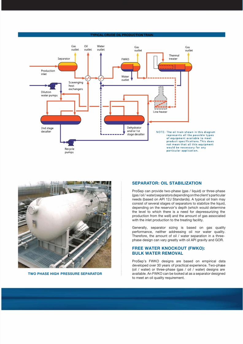
SEPARATOR: OIL STAbILIzATION
ProSep can provide two-phase (gas / liquid) or three-phase
(gas / oil / water) separators depending on the client’s particular
needs (based on API 12J Standards). A typical oil train may
consist of several stages of separators to stabilize the liquid,
depending on the reservoir’s depth (which would determine
the level to which there is a need for depressurizing the
production from the well) and the amount of gas associated
with the inlet production to the treating facility.
Generally, separator sizing is based on gas quality
performance, neither addressing oil nor water quality.
Therefore, the amount of oil / water separation in a three-
phase design can vary greatly with oil API gravity and GOR.
fREE wATER KNOCKOUT (fwKO):
bULK wATER REMOvAL
ProSep’s FWKO designs are based on empirical data
developed over 30 years of practical experience. Two-phase
(oil / water) or three-phase (gas / oil / water) designs are
available. An FWKO can be looked at as a separator designed
to meet an oil quality requirement.TwO PHASE HIGH PRESSURE SEPARATOR
TYPICAL CRUDE OIL PRODUCTION TRAIN

8/4/2019 Upstream Oil Processing
http://slidepdf.com/reader/full/upstream-oil-processing 3/6
DEHYDRATOR: MEETS SPEC
OIL REqUIREMENTS
ProSep’s unique vertical grid design allows us to employ a
horizontal flow pattern that can be operated either as a two-phase (oil / water) or three-phase (gas / oil / water) unit. In
addition, we can combine our mechanical coalescer elements
with our vertical grid system to ensure product specification
adherence. Normally, dehydrator designs are employed in
production fields where external heat sources are available
or the number of process units is dictated by the heat load
requirements. In the latter case, a line heater may be utilized
to meet the heat load requirements. To meet high throughput
requirements, we offer double-ended designs with multiple
electrostatic zones with variable field densities.
DESALTER: REDUCE SALT
CONTENT IN THE OIL
ProSep can provide desalting systems to meet your
requirements. Depending on the salt content at the beginning
of production and the outlet oil specification, crude desalting
can be accomplished by various processes. We go from
simple dehydration up to multiple stages of dehydration
combined with dilution water injections to reduce the overall
salt concentration. Dehydration units (thermal treaters,
dehydrators) used to desalt are called desalters.
As the name implies, only free water is removed from the
production inlet stream, leaving the emulsified water in the
outlet oil stream. The percentage of emulsified water in that
stream depends on the oil API gravity. Meeting this requirementrequires operating at a particular treating viscosity combined
with a calculated retention time. We address the treating
viscosity requirements by heating the production stream as
shown in the diagram (left) with scavenged heat or by adding
internal firetubes to the FWKO itself.
THERMAL TREATER: MEETS
SPEC OIL REqUIREMENTS
ProSep’s thermal treaters combine both heating and
coalescing capabilities in one efficient process unit. ProSep
designs the heating section to meet the treating viscosity
requirements of the coalescing section. Two-phase (oil /
water) or three-phase (gas / oil / water) designs are available
with either mechanical or electrostatic coalescing elements.
Typically, thermal treater designs are employed in production
fields where the number of process units required is based
on the coalescing design and not the heating demands. The
treating temperature for a thermal treater is considerably
higher than that for an FWKO in order to meet the stricter
water content specification by removing the remaining
emulsified water from the process stream.
THERMAL ELECTROSTATIC TREATER
ELECTROSTATIC DESALTER

8/4/2019 Upstream Oil Processing
http://slidepdf.com/reader/full/upstream-oil-processing 4/6
DESALTING TECHNOLOGY
A system can desalt by two methods: (1) dehydration
and (2) dilution, or changing the produced water
solution concentration. Most of the salt (99.99%) is in
solution in the water, so removing the water associated
with the oil also removes the salt at the same time.
If the salt concentration is very high, however, then
even removing 98% or more of the associ¬ated water
may not meet the oil salt content specification. The
next step is to reduce the salt concentration in the
associated water by mixing it with dilution water with
no salt (freshwater) or a smaller concentration of salt
(brackish water).
Again, several stages of dehydration and dilution may
be required to meet specification. This is dependent on
the inlet production cut and salt concentration.
The ability to introduce the dilution water into the
process stream without creating an emulsion and at
the same time developing a homogeneous mixture
between the dilution water and the brackish produced
water is essential to this design. ProSep offers ProSalt
an injector / mixer system that improves efficiency in
water consumption and downstream dehydration.
TwO-STAGE DESALTING SYSTEM
INLET
STREAM
1ST STAGE DESALTERINJECTOR
WITH MIXER
DILUTION
WATER
INJECTOR
WITH MIXER
2ND STAGE DESALTER
RECYCLE
WATER
OIL
WATER
SALT

8/4/2019 Upstream Oil Processing
http://slidepdf.com/reader/full/upstream-oil-processing 5/6
one problem. This can be illustrated by designs that allow the
following:
• Operation with a gas phase, thus eliminating the need for a
degassing vessel before an electrostatic dehydrator.
• Installation of mechanical coalescers in the inlet section toreduce the water cut to acceptable levels before entering
the electrostatic field, thus increasing the inlet water cut that
a dehydrator can process.
• Placement of firetubes in various locations in process
systems to improve efficiency and streamline necessary
equipment.
INTERNALS
• Inlet Momentum Management (Momentum Breakers, Vane
Diffusers, Cyclonic Distributors)
• Gas Demisting (Mesh and Vane Mist Extractors, Axial FlowCyclonic Demisters)
• Viscosity Enhancement (Firetubes, Heating Coils)
• Plug Flow Distribution (Perforated Plates)
• Oil Phase Coalescence (Mechanical Elements, Vertical
Electrostatic Grids)
• Outlet Phase Management (Vortex Breakers, Weirs)
• Solids Removal (Sand Wash and Extraction Systems)
• Firetube Protection (Detection and Wash Systems)
APPLICATIONS
• Liquid stabilization through the removal of gas
• Removal of free water from the oil phase
• Removal of emulsified water from the oil phase to a
specified level, or in the case of desalting, to allow the salt
to meet a specified maximum
• Reduction of salt concentration, which may be required to
meet specified maximum (via dilution water)
TECHNOLOGY
ProSep’s separation technology is based on a horizontal flow
regime. From FWKOs to desalters, the horizontal flow pattern
allows us to provide two-phase and three-phase designs that
maximize vessel utilization for each component.
As the process progresses through the vessel and the water
droplets suspended in the oil phase coalesce into larger
droplets, they finally reach the critical particle diameter where
Stokes Law begins to apply. Stokes Law defines the terminal
settling velocity of a particle of a particular size as it falls
through a fluid. The terminal settling velocity is perpendicular
to the horizontal process flow velocity. This can be particularly
critical in equipment designed to produce 0.5% BS&W or
less where the droplet population is reduced and smaller
coalesced droplets may be formed. As you can see from the
vector analysis below, a unit utilizing an upflow design creates
a velocity vector directly opposite to the vector created by
Stokes Law. The conclusion is that if all parameters in Stokes
Law are fixed, a horizontal flow regime can remove a smallerdroplet size, which translates into a more efficient system.
A big advantage with a horizontal flow regime comes with the
design of a vertical electrostatic grid system. As the oil phase
progresses downstream through the vessel it can be exposed
to multiple stages of electrostatic fields of varying potentials.
Built-in adjustability allows these fields to match the water
content remaining in the oil phase, thus ensuring complete and
efficient dehydration. One additional advantage is the facility
to incorporate mechanical coalescers in combination with
the electrostatic grids. These coalescers can be placed in the
process stream to provide either bulk or polished coalescence.
MODULAR CONCEPT
In order to provide the flexibility demanded by today’s
business model, ProSep utilizes a modular design system to
develop equipment that can provide solutions to more than
Horizontal Flow Design
Critical Particle Size
Upflow Design
OIL
OIL

8/4/2019 Upstream Oil Processing
http://slidepdf.com/reader/full/upstream-oil-processing 6/6
About ProSep
ProSep is a technology-based process solutions provider
for the upstream oil and gas industry.
The Company designs, develops, manufactures and
commercializes technologies to separate oil, gas and
water generated by oil and gas production.
ProSep’s innovative offerings have been awarded three
Spotlight on New Technology Awards from the annual
Offshore Technology Conference in Houston in 2005
and onwards, comprising the proprietary technologies
ProScav, CTour and ProSalt.
A CUSTOMER’S ExPERIENCE
ProSep personnel were involved in the supply of an advanced
design horizontal coalescer installed in the Gulf of Mexico
platform in 1998, where the coalescer’s design enabled it to
significantly exceed design capacity while simplifying opera-
tions. Design features that aid in enhancing performance in-clude: horizontal flow to minimize water carry-over with the
bulk oil phase, cyclonic inlet device to smooth the pipe-to-
vessel transition and degas the oil at inlet conditions, baffles
to distribute oil flow evenly across the vessel cross section,
multiple externally adjustable electrostatic grids to vary field
density and allow improved coalescence, and enhanced coa-
lescence packing to optimize removal of water droplets coa-
lesced by the electrostatic field.
The existing upflow coalescer was frequently unable to
achieve 1.0% BS&W in oil effluent at less than 50% of its
design flow rate, while the horizontal flow electrostatic treater
consistently provides <0.4% BS&W at 120% of design ca-
pacity.
The equipment has become the standard design approach
for this client.
REfERENCES
Available upon request.
fOR MORE INfORMATION
Contact your nearest ProSep office
www.prosep.com
ABOVE: The 50,000 BOPD horizontal electrostatic treater (left)
consistently exceeds design capacity, while the conventional
treater (right) is unable to meet its 35,000 BOPD design
capacity. This is accomplished with a treater that is only slightly
larger than the conventional treater. APPLICATION: Crude OilDehydration
CANADA
+1 514 522 5550KOREA
+82 2 521 3668MALAYSIA
+603 2715 6680MIDDLE EAST
+973 36 460142NORwAY
+47 55 52 94 00UNITED STATES
+1 281 504 2040