upon variable motor · testsuponavariablereluc tancemotor by rayleeklyhorr...
TRANSCRIPT

Hon & Timm:
# »
4
A
Tests upon a
Variable Reluctance Motor
Elec. Engineering
'^:-Vt:-^B. s.
19 4
I

f 1^- ^f. i. ^
# ^
.
- "^r^- •'^F^- ''J^^^'
^ 4. ^.
4^
4
4
BOOK
f#4
r f # -it
-X
4
UNIVERSITY OF ILLINOIS
LIBRARY
CLASS VOLUME
f f ^ f
if'
r
4
# ^ # f 111 4^ #

1h
i 4
a* *>* ^ ^ ^
# ^
^ f
# # -H^^'
# ^ ii^-' ^ ^4 # f.^ ^
#,
#e^ # if 1^ #^ i<fi^ ^
^ ^ ^
4
if
1^^-.
4k ^ ^r ^ -i^ 4 >
^ ^
~ ^ ^ ^N*^ ^ /-^ #
^ -1^- -If-
4-1^
1^
4
4^- 1^ ^ ^ ^ 5f
^ # f # ^
4' 4^- ^
4 ^
# --4-i^ ^


TESTS UPON A VARIABLE RELUCTANCE MOTOR
BY
RAY LEEKLY HORR
PETER FREDERICK WILLIAM TIMM
THESIS
FOR THE
DEGREE OF BACHELOR OF SCIENCE
IN
ELECTRICAL ENGINEERING
IN THE
COLLEGE OF ENGINEERING
UNIVERSITY OF ILLINOIS
PRESENTED JUNE, I9O4


UNIVERSITY OF ILLINOIS
May 27, 1904 i»o
THIS IS TO CERTIFY THAT THE THESIS PREPARED UNDER MY SUPERVISION BY
MY.....L.E.E.KL.EY....M and PITER FREDERICK YULLIAM Timi
ENTITLED TESTS UPON A YARIABLS RELUCTAHCE MOTOR
IS APPROVED BY' ME AS FULEILLING THIS PART OF THE REQUIREMENTS FOR THE DEGREE
OF BaclieloT. of Science in Electrical Engineering
HEAD OF DEPARTMENT OF Electrical Engineering
.
66 165

Digitized by the Internet Archive
in 2013
http://archive.org/details/testsuponvariablOOhorr

I>TTHOT)UnTIO]T
Ginoe thn introduction of electricity as n, notiye pov/er, the
electric motor has heen rapiil^'' increaslnr: its rarif^e of usefulness
In the variouf? industries, where power is used. This is e spec i ally
true in large factoT-ies where it is necessary to transmit power at
Ion;-; " di stances , and in such cases the loss in transmission, either
"by shaft in^-^ or steam, entails a f^reat loss of power. This loss has
"been overcome to a f^reat extent by means of electrical transmission
and the use of motors.
.^ter the electric motor had proved itself to he a satisfactory
means of convert in^^ electric power into mechanical power, the ques-
tion of a variable speed motor presented itself. The series motor
cave such speeds but the speeds were not stable; the shunt motor
gave a constant speed but the speed could not be varied through any
great range without sacrificing a loss in eff iciencj'-. The object
sought for was a motor v/hich would give a variable number of con-
stant speeds and thus do away with all manner of mechanical speed
changing devices.
Several motors to meet this demand have been designed and put on
the market. The .Sto\»/ Ifotor built by the Stov; M*f'g Co., "Binghampton
,
N,Y,,represents a type of motor v/hich meets the a,bove requirements
and it has been the object of the a.uthors to make a,n exhaust i""-e test;
on one of their motors and examine its performances.


T) K R C R I P T T N
One of the earliest attempts to change the flux in the riaf^netic
circuit of an electric machine vms made "by Thos. A, Kdlfion in IBRn.
In that year Edison secured a patent which illuFitrates and descrihcs
the enplo;;'"nent of a hlnii; of jna^jnetjc material of conical form, ad-
justable in a conical opening in the hack yoke of the field magnet.
The patent says:
" I ^lake use of the principle that the pov/er of an electro-magnet
can he weakened by diminishing the mass of the yoV.e connecting: the
cores, and that such power can be strenf^thened by increasinn; the maoe
of said yoke until maximum power is attained. In applying this prin-
ciple, I provide the 2^oke of the field of force magnet of a dynamo or
magneto-electric machine with a, movable portion, the position of
svSiich ca.n be var'W^d so as to affect the mass and conducting power of
such :''oke, said movable portion acting as a magnetic r'jrnnit regula-
tor."
As far as the authors are able to determine this is the first
patent that was ever issued, covering adju^stable means for governing
the field strength, in a dynamo electric mac/iine by varying the re-
luctance of the nagnetic circuit,
A few years later a patent was issued to Philip Diehl on a d^maiio
electric machine, the principle novel feature of which was the means
for varying the length of thp a-ir gap, the two limbs of the bi-polar
field magnet being connected by a hinge joint.
The total relucta.n(?e o"'"' the ma.gnetic circuit in the Edison method
is varied by yarying the reluctance of the iron portion of the cir-
cuit, while in the j^iehl method the length a.nd therefore the reluct-
ance of the air gap is varied. Both


- 3 -
!nptjiofis p.fford an ahsolut.ply con+-,5 minuo, rnnr.e of ^rarlr-tjon v/j thin
their limits and the cont rollln.-: devjcfs are po simple that a de-
ran^jonirnt 1s almost impossible.
The abo^^e methods have iiot >een put into practice hecaupse they io
not offer my important adAranta'-ies over the shunt rheostat method of
control. Whether variable resistance is placed in the field circuit
or a variable reluctance in the magnetic circuit, the effect is prac-
tically the sane and the efficiency is also practically the same in
the two methods.
In the case of {generators, in which the field strenp;th is con-
trolled from the •switch-board, the use of a rheostat in the field
circuit i'o the only feasible method of control, b\it with motors it
i is different. While the speed of some motors, such as railway,
elevator and travelinp; crane motors, is, throu^^h necessity, con-
trolled at a distance, the majority of controllinf^ apparatus for
other motors may be placed on the motor itself or become a part of
it.
Althou^^h the tv/o methods, for the control of speed, cited above
;
give good regulation, the range of speed is so small as to be im-
practicable, since an increase in range will cause prohibitive
sparking; the range in a well designed motor is from normal speed
i to about one third above normal speed,
Wlien the flux in a magnetic circuit is -varied either by means
of a fiplrl rheostat or by change of reluctance In the circuit, the
' densitjj' of the magnetic flux, over different parts of the pole face
varies uniformly. If the field current is decrea,sed, in the case of
a shunt motor, the volume of the flux is also reduced and the rela-
tive distribution, is practical!:/- una.ltered. If such a machine


> 4 '
wrrr ftconomioally des.iiiripd for oporat.ion ;it normal Rpeed, h/ reduc-
ing the fif^ld current a point, will soon "bo reached when the frinrc
of itiaf^netic lin^s at the pole tips will he inadequate to accorrrplj sh
sparkle ss corrnutat ion at full load.
The reluctance methods of »ireakeninc the field strengths of hoth
Diehl and >jdison, do not materially affect the relative distribu-
tion of flux over the pole faces and in (;onsequenoe are suhject to
the same limitation in the natter of range of speed as is the case
in v^hich a field rheostat is used.
Having looked into the merits of the aho-re methods of speed varia-
tion we now come to a description of the special construction patent-
ed hy Frederic A. Johnson, in which the speed variation in machines
of lOf^and over is four times as great as can he obtained by change
of field resistance or variable reluctance methods as described
above
,
Since it is seen that in the ordinar2'' field-regulated shunt motor
the speed cannot be increased bejrond certain narrow limits on account
of the inadequacy of the fringe at the pole tips, it is therefore
clear that if means are employed by v/hich the flu:: at the pole tips
is maintained practically constant irrespective of changes in total
induction in pole piece, the speed may be materially increased wiih-
cut causing sparking at the commutator,
Fo essential difference exists betv/een the specia.l motor herein
described and those of ordinary design except in the construction
of the pole piece v;hich is made hollov/, and within which is a. solid
cylinder of wrought iron, adjustable radially. When adjusted to its
innermost position this cylinder, or plunger as it is called, extends


- 5 •
t>irou(^;h the inner end of the pole piece thUB forminp; a portion of
the pole surface and as its cross section is much ^i^eater and its
perrneahility much h^i n;her than the inductive section of the pole
piece, it carries the larrer portion of the flux. These movaT)le
cylinders are ino-"^ed radially by means of a screw, operated "by a hand
wheel situated on the top of the machine. This hand wheel operates
the c^'-linders in the different poles simultaneouslj'-, loy means of
a bevel f^ear
.
Results secured in the motor "built under the Johnson patent will
be shown in the following; tests vjhich the authors made on a 10 H,P,
220 volt motor built by the Stow Manufacturing Company, Bin^hampton,
IT.Y.


- c
TESTS
1. Hand Wheel Ref^ulation
2. Stray Power
3. Fony Brake Test
4. Potential Curves around CJoinmutator
5. Saturation Curves
5, Distribution of Lines in Air-gap
7, Measurement of rises of Temperature
8, Leakage Coefficient
9, Resistance of Armature and Pi^ld and In-
sulation Resistance of Armature and Field.


- 7 -
H A IT D W H E K L K T! a IJ L A T I O ?T .
The hand wheel regulation was obtained "by keeping the impressed
3?. "P. constant at 220 volts and taking the R. ?, for different
positions of the hand wheel from minimum to n^jximum speed. Curve
plotted shows the relation ^letween the hand wheel turns and t?. p. m,
the R. ?. "A, ranging from 610 to 1320 (See curve #1).


- 3 -
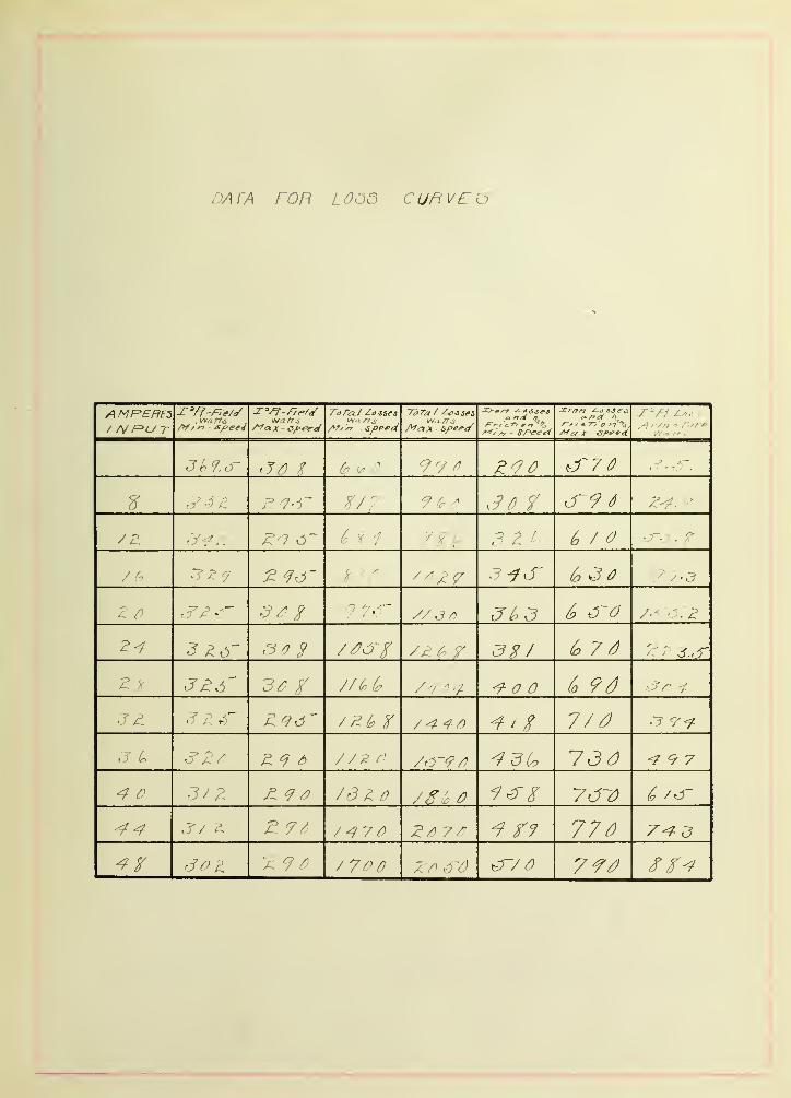
T R A Y P ' W 7? R
In determinin/;? the atrai'' power or the arnoimt of power required
to run the riaohine at no load, the motor was bo connected that
the field current armature current, and voltage across "brushes
could he read s1multaneousl3''. Readings of field curre-nt , armature
current and voltage were taken for different positions of plunger
from miniraum to maximum speed. Stray power was then calculated froM
the following formula: Stray power , CTruves were
plotted hetv/een stray pov/er and R. P. M, and between stray power
and hand-wheel turns (See curves # 2 and #3).


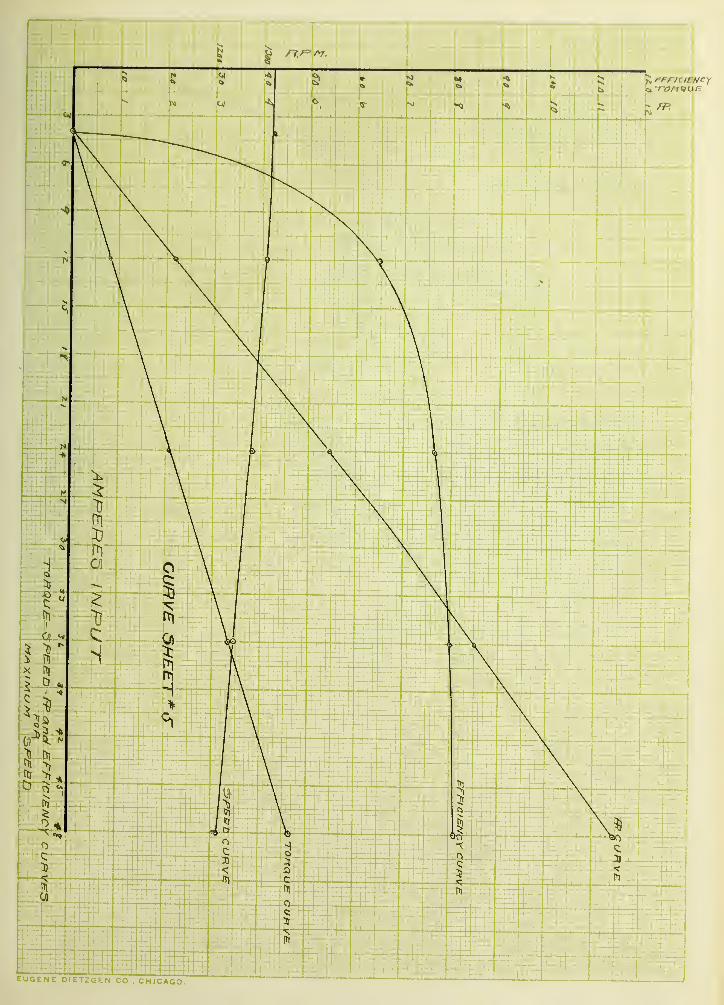
pT^OTTY BRAKl? TERT.
Pony brtikft test was nadR in order to shov/ the relation "between
torque, speed, F.P, output and efficiencj'' and amperes input. The
apparatus was connected so that the total current delivered to the
machine, the field current and Lhe voltage could "be read simultan-
eously. The pon3'- "brake was so arranged that the pounds pull v/as
read directly on the scale. Readings v/ere taken from zero load up
to 12 H, P. for minimum and maximum speed, CTurves were plotted
showing the relation "between torque, speed, II.P. output and effic-
iency, and amperes input; also the relation of efficiency to watts
output (See curve sheets #4, #5 and #5),


- 10 -
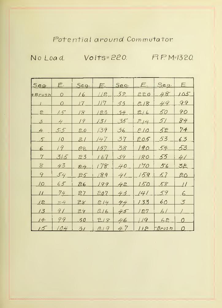
POTJ^NTIAL AROiriD fTO?T MUTATOR,
Thft rise of the Int ftf^rated potential aroimrl the commutator v/as
measured hy ^'fordey*?; method involving the use of a single exploring
"hrush and a voltmeter. One terminal of the voltmeter was connected
to one of the hrushes of the machine and the other terminal was
joined hy a wire to a small pilot brush which was pressed at equal
intervals, against the rotating commutator. Readings were taken
half -way around commutator and curves plotted with commutator seg-
ments as ahscissae, and volts as ordinates. Data was taken at no
load, maximum and minimum speed, and at full load, maximum and mini-
mum speed (See curve sheets #7 and #8),


- 11
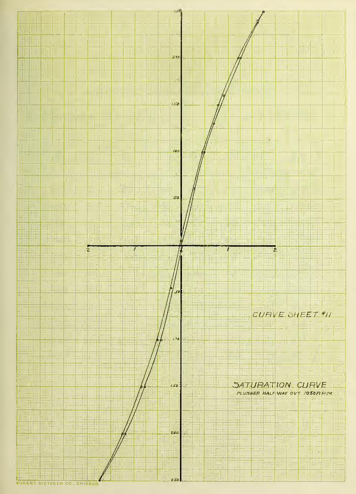
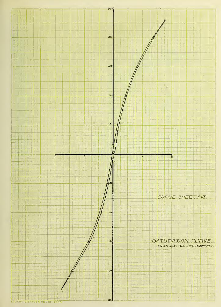
S A T U H A T I !T CURVES.
In finciinf^ thft saturation curves the nachine was "belted to a inotor
anci run as a d^rnaiio. The shunt field was excited from an external
source, first passing the current through a variable resistance
and an ammeter, A voltmeter was placed across the terminals and
the pressure read corresponding to each value of field current,
Values of current ranging from to maximum, thence "brxk throu^*
to - maximum and hack to again, were used for five different
positions of the plunger i.e. all in, l/4 out, l/2 out, 3/4 out and
all out. Curves were plotted with the exciting current as ahscissa
and volts as ordinates fSee curve sheets #9, #10, #11, #12 and #13).

r

12
Dlf^TRIBIJTIOF OP WrlP^TIC LINES IM AIR-GAP.
The field of the maohino was excited with the normal exciting
current, voltaf^e beinc kept constant at 220 volts. A test coll of
ei;-^ht turns embracing two teeth on armature was connected to a mil-
Toltmeter T,nd the deflection of the needle noted vyhen ^the field cir-
cuit was suddenly'- broken. Readings were taken half way around the
arma-ture at intervals of four commutator segments for five positions
of the plunger; all in, I/4 o\it,I/2 out, 3/4 out and all out.
Curre3 were plotted with commutator segments as abscissae and de-
flections as ordinates (f^ee curve sheet #14).


- 17>
mAr^lTRFrX^VlT 0? RISE 0? T>1^'[P>']RATTmE.
^otor was "belted to a rl^rnfUTio an;l a load of 10 "^T.P. put on rnotor.
Temperature of the room and eaoh part of the inachine was taken TyO-
.fore starting, Ma-^hine was run four hours and then the temperature
of the room, armature, commutator, field coils and hearinf^s was
noted. The temperature of the field coils v;hile running rose from
22-I/2 deftrees C. to 42 def^rees C. and when the machine was shut
do\vn the temperature rose to 55 degrees C or 32-1/2 degrees C ahore
the temperature of the room; the temperature of the armature rose
from 22-I/2 degrees C to 51 degrees 0.; the comjnutator rose 44-1/2
degrees C and the hearings 22-l/2 degrees C. All Tieasurement s "by
thermometer
,


- 14 -
T, V A T/- Ti: r? E V V I rr I E N T
The ratio of the total flux generaterl liy a field m^ne-t to the
flux passing throu^;;}! the armature i.e. the leakage coeffici'^nt is
found in a manner described below.
A test coil of a few turns was passed around the top of the field
magnet, through which all of the armature flux must pass. A normal
exciting current was passed through the field coils and a quick
break switch put in the circuit. A loJ lli-"5roltmeter was connected
across each of the test coils and the deflections were read when the1'
fT**?-'l 3urrent was "broken, for five different positions of the plungerj
all in, 1/4 out, l/z out, 3/4 out and all out. If Of and O^^ be the
deflections observed in the field coils and ar2iatnrf= coils respect-
ively, and since the two test coils were alike as regards resistanceOf
and number of turns, gives the coefficient of leakage without^a
further calculation. The coefficient for the bottom of the pole-
piece and the yo'k.e was calculated in the same manner.
Curves were plotted with hand wheel turns as a,bscissae and co-
efficients as ordinates (See curve sheet #15).


- 15 -
Rf^niSTAN'":}'] 05^ ARJTATlIK:i'l AKD 7iyj.D\
IMr,TIT,/VTIOX R]^SISTMCE OF ARTfATimK AMD ?I>:LD.
A fri-ven current, was passed throu^^h the rtrnature v/jth a voltmeter
connrcted across the brushes. Readirif^s of current and voltage were
taken and the resistance found to he .388 ohms, Tiic resista.noe of
the field was ohtained in the sana way and found to he 144.3 ohrns.
Por ol.-'taininc the resistance of the insulcttion of tlie armature,
one side of a 500 volt circuit with a voltmeter in serfes was con-
nected to the shaft and the other side to the commutator. The de-
flection on the voltmeter was noted when the resistance v:f,f short
circuited and when it was in series. Let and ~ t?iese deflect-
ions respectively, and R the resistance of the voltmeter. The re-
sistance was then calculated from the follovinf; formula :
The r33ista,nce was found to he infinite since was zero.
The resistance of the insulation of the field coils was obtained
in the sane way and found to be infinite.


- 16 ~
C K c L TT R T K .
After havinfc tested this motor and observing its characteristics
the authors find that tlie iiotor 'ereJn dencribed differs from all
others in that with constant potential at the terminals it carries
its full rated load at any speed within the limits of^ 1?0^ variation
and with an efficiency which is almost independent • of the speed at
which it is operated; the variation of efficiency "being al^out 7^,
The machine showed no more signs of sparking under full load at
maximum speed than an ordinary shimt wound machine run at a speed of
30^ ahove normal.
In comparing the v/eight of the machine herein described with other
machines of 10 H.P. and speed of from 630 to 750 R. P. M, we find
that the ^to"i7 motor is slightly'- heavier. Below are given the weights
of a few of the "best shunt wound iniic?iines on the market.
Shipping weight.
Stov/ 1700 Ihs.
C^eneral Electric 17A0 "
Sprague 1185 "
Bullock 1250 "
Western Electric 1510 "
Crocker Wheeler 1520 "
With regard to torque it was found that it varies inversely as
the speed axid directly as amperes input.
1


n
DATA FOR HANU M/liEEL REhULA TIPN AND O THAY POWEF^.
-L Ff F.'M. / A/ -f'lJ T /: A/
h / //I/ /
p /• O J
A A J A . / /Si 7^ 'y ^1^ V 4 / 7 ^-^Z
iL (' /) / / ' ^ / X~ /'I i J
U J -f o Ay
K O C.3 a
1: ? ') A . C / /' /J/ t " ,F A ^ A, ^ / O j
2 A J A J'0~ / 74 M "
^ T ^) ^. /// f ' b „ S ly /
2 X ^ ^. 1. / / 6 J '/ ' S 7/
//'^/ cf 7/ Z.C Z
A ^ ^ J' 7/
J Z 1^ 4 72
2 7 /d07 .2 L,


1
I
JiOO
tUOtNt Ci\Ll^L.tLi\ 'wO., CHICAGO.


IS
Data for Speed, Torque, Ffand Efficiency.
Minimum Speed.
T E WartsIhpoT DutPVtTorque
660 o n
1790 /.5/ /o. ^/r
IP. 7a
/C. ;dSPO 77./
^0 P. Pn .^<?.^
&^ PP?
^, 2-/0 ^^./
^9 7 y ^E-7
f/7
^0 ^5 /cos
/A/ 952^0 '^76


<i ronaijr
EUGEr. ^ C I ^(^LiM CO., CHICAGO
-1
51


Data for Speed, Torque, FPand Efficiency.
Ma\i mum Speed.
i_ tl Input. Tor<:tue e ft.
o C)
O IT) ?i / 72_?r if on
/A / cL^^ -2 -T J3^ f/ <o / //
^.^^ ?
ay
/B7n
yo^o 79'S
^Pn V9Pn d-o.
Zr.o 9 ^9^0
^^•^


Potential around Commutator.
Full Load Volts=eaO. R.PM = /£7Q
E ^.
r0ru^
h
3?.
1 o 11 13"^ 2,1 L Cz.
3^ so 37
19 /^^ 3^ 3-/
17 /s^ .5^
^1 /^^ 37 3-5 53-
6 3K y^o S^ 30'r no 3)9r £38- 177 3~(> /6
9 ^0 IR7 S7 7
JO hn S^II 7/ UP. 3-9
1^ mo AO /
97 -T
11^ 30 7715- 19.^ .5/ 75 A3


F^otenf \o ] around Commutator.
Full Load Volts-a£0. R.PM?=fr75
//:> y// 2 / ? 91
1 /r
'^-
7
9
1 3 2./ /951'^ ep
Zf>
/^^ ^0
9 s'59 I9p IST^
?6 1^^ -a.
11 /37 3/30
//9 ^/ n
/-^ 90 no O
2/9 ^7

Potential around Commutator
No Load Volt3=8eo RPM.^I32C
E- H.
ZDS'
1 //7 99
P /.r If ^/ 4 so ?0
—4^ 19 -^/^ s/
B~0
10 P^l ^3
P?. S37 23 it>i ^/8^ IVO 5^9 1^9 EC)
JO ^6 J99 i^n
II ^71
//
hi /
119 A?. n
J/ n


Potent! a I around Commutator
No Load VoltS'SaO R,PM.= 6/0.
F. S ea- B.
.^^ //e
1 o /7 .1 op
/ j^n -TO (/o
/? an ^/ ^/
f f>9
7 /6o J7
170 3^7 69
/W 194-
/SS a/
174-
// ^7 P/S
/P
77 a/^ ^ / /
^/ 2/8- ^7 ^Brush

C/l
rro
o
Q C


EUGENE D!t,iut.N CO., CHICAGO.


DataforSatut-ation Curve,
Plunger in
Tf E Tf
O To -hMaximam±Maximum to C) Oto- Max'itvijm ^Mai (mom To O
/.5-ff /.6'G
GO •32 GO
fro /^O /,0H 80 /^O
/OO 7 /60 /OO S9 /60 ?5
/^O 7/ l?~0 .7Si /^O
/^O ^^ /an /^o .^^ /^O .66-
/60 /OO /U) /OO
/fro //H S^o 1^0 A/S HO ^/60 /d^ 60 •5
/,5'^ ^7A6r 5


l<t

Oata for Sofurat/on Curve.
Plunger 6 turns out nJ^M^865
E E Tf E
O to -h MciJ( » rnom /m TO f? O to — Mclit imum
4-/ aoo /. -^f
^0 /.Z/ 5GO IGO /.05
. SO 140 30 /^o .^9
100 .6a 7a /CO 1^0
/2.0 loo ia.0 100
91 /fO so
GO •5/ /^o /// 60 5
/so ISO
aoo ^00 /.^^
o


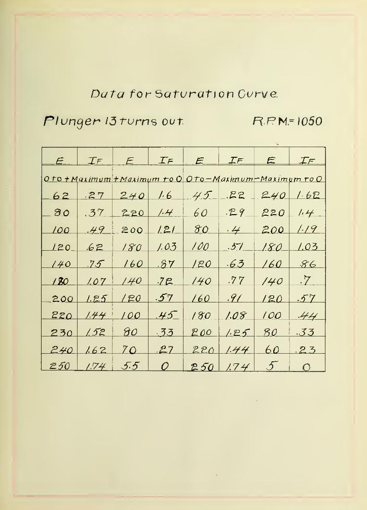
Data for Saturation Curve.
riunger 13 turns out R F'H^lOdO
Tf E Tf E Zf Tr(JTQ f MQKimum f- Maximaim 1-0 O Oto-t^ —Maxim vtn TP
.27 Z^O ay (7 / 6U
90 ^^0 /'^
lOQ /'/9
1^0 /^a /oo /.05
7sf IGO ^^3
I7D /.07 /^O 7£ .77 /^o
2.00 /BO ^S7 /60 ^9/
A^^ 100 .yi" I?f0 lOO .^^
/.5'E So 35 'ECO ?>o
U?i 70 .^7 /yy 60
^50 /.7^ S5 ^^0 /.7V S O


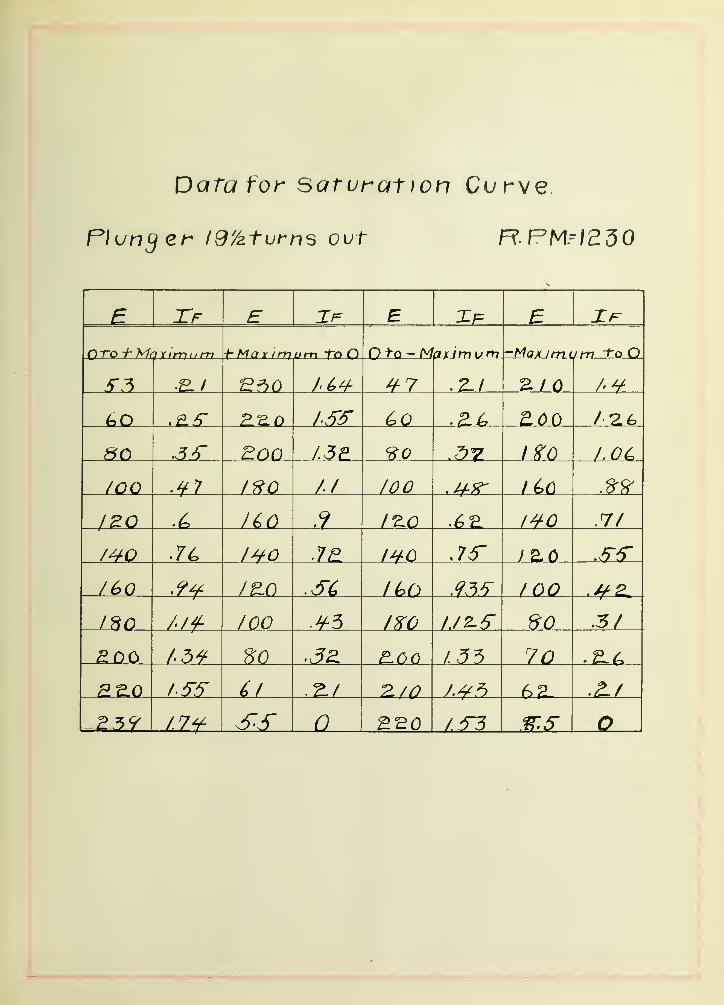
Data tor sarurat )on Curve.
nunger /9/aturns out R.PM5I250
£ Xf E E 5 Xf
n To -h 'Mo tIm um h Max imutn To O Ofo- Maximum -Max im (Jm To O
/^^ H-7 .E./ E / /•¥
/.-ST ^0 EOO
so Boo L5E /^^
/CO // /oo /^O
jZQ • /CO 12.0 .7/
/^O IH-O ,75" JZO
/Go /U) ICQ
130 //f /CO fKO do .5/
£00 I'M so 70
/5-5- ^/ Z/0 62.
^23^ /.7¥ n


Data forSafuf^at/on Curve,
Plunger aetunn^ out R.PMH320
E Tf
f MaximumToO X)to-Mcuitnom -Max inlom ToO
./^ A /66
/.^^ Go .^(^ /J?
fro A/E 8-0 /^O /•/^
100 /OO /60
.75 / S.o /^O 73
/^o /^o
/6a /OO /60
/^o //f 3-0 3 /^O 80 •3
139 60 f>0
d'O d'O
2.^0 /.7S A7^ 6


D^'IA FOR nAbNETlC UJ^) THIBUTWN IN Aif< OA I
Coil h/- ^J/ //*^
L^0 SI // on J/ /i
CO// r
O /? /) /d> " / /) / /)
i- ' b / A I) / 7/)^
? /
J 7 4 / 6^ [) y 7 r y y 4> S
/ 7 4 / ^ / 'F/ /) /d Lo ^
. r /V- /' h / ^ //^ /L / /)4
:^ ^ ^ d 7L Z ^
,) Z4 /
- U4 T? - -40
^ £ -J 74 " / / d
- I7Z u /, ' ^4 i> 4
-/ 7^ 4 ^ /oo ^ <44
- /'/ L 4i "/J (0
f r -J 60 ^/^ ^ 7 A Z -// /7
' 2 2 / f
/4 / d / c/
^ /n f) /Si- // c ^ //>^ 6 / ///)
4 / Z b ^ / /? ^ '/^ h 4
^ 8 / 7 K 7L h 4 ^ / 7>-^


DATA FOR COEFFIC/EN r OF LEAKAGE.
E Dcflec fi on F*^/' Co// </.5 / /'
^ ZO / 3 / //7
/ Z C'Z / u2 ^ ^ 9 ZZ..F / /J
^o Z / /7±
7Z // /
Zz //4 z?.s J/7
Z ^ ^7 ZJ. 7
76" //•/ / 3
/ 7
Z Z zc
To af FiP /e
B Z :zoo 7-3 9
ZZO / ^ z
zzo J ^-^ / d'O / 3
ZZo / a ^ cJ/ /. 6^0
z /// ^7-7 / zc
ZZO /^^ 7 07 //?
-JO 7/9UZ Z L /' /d' / 3
ZZo //^ 2Z-^ //^ '
2^0 /a L ZJ.Z //^


lU
o
I'LUOu
Top of Pole.
YoKe.
Baitom of Pole.e>
-9
-o
HAND WHEEL TURNS."5 7a /6 £0 ll6
GOEFFICiENT of u.EAKA's:^E.
VOLTS -eeo
CUHVE 5HEET^JS

DATA FOB 1000 CUF^VEO
A MREREZ/ /\f f=>U T ,'>f / n spee4
IV. 2 /T"^^ not «
& & 7^ 99 ^ Z9 d^7 7)
' /.
JO 7
9S'(r 3 Z ^7 7)
/ /, '^.r (o 3 7) ;^
^' /I // 3 ^ J h 3 ^ c^o
2^ /T'. 7^ 7 ^ 7 d
3/: / 6 9d
71 Z /^^ / 7/^ 7^
,T ^ Z^ ^ / / ^ r 73 7) ^97^ J / /i /d ^ 7g.c ^ 7^-7) ^
Z ?d 7^7 ZT) 7 7J ^ 770A '7 / 7^'^ x '.^ '-T7) 7'9'7J


^ ^ ih -ih ^ 4^ ^^
^ ih ^
#-
^ ,' ^ ^ # # ^
J/^fc, :
^ if- f i' r ^ #- -Sfr ^ f--T^ # Tii
^ -f f f ih ^ ^ f f^f,-
^ ^f, ^ ^ f ^ >f 4 ^ ^ # '
f^::,:-|^-:>;^-^' ^ 1{- ^ >Ki ^f- ^fr #

"^^^v'"'^
4.
^ #- lift
^p*^ "^^l^ ^1^^
f it'-
f
* ^ i^^
ffc- -# ^ 4 4r^<,
^
if^- , ^ il^" ^
