upgrading old interlocking systems - netirail...
TRANSCRIPT

Tudor Popa
Upgrading old interlocking systems
NeTIRail-INFRA final conference
Ljubljana, 24 May 2018

Existing Situation (1)
• CEM (Centralised Electro Mechanical) Interlocking Systems are still used for lower density lines, where shunting is a rare event.
• Integrating new automatically operated devices into the current CEM interlocking is problematic.
• Signals and switch points, are handled locally, or from remote, by steel cable transmission
• CEM devices status is available only to the person who operates in that location and communicates to the central operator signalman by phone
• There are not automatic data logger for historical CEM operations and events
2

Existing Situation (2)
Switch point local handling mechanism
3
Steel cable as remote handling
mechanism for signal
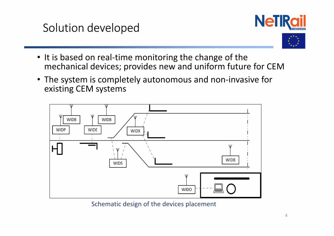
Solution developed
• It is based on real-time monitoring the change of the mechanical devices; provides new and uniform future for CEM
• The system is completely autonomous and non-invasive for existing CEM systems
4
Schematic design of the devices placement

Advantages of the using system (1)
• Help integrating for new devices into CEM system
• Wireless communication
• Total autonomy, in terms of power supply, using batteries and photovoltaic cells.
• The system supports restrictions from harsh environment and long-time functioning
• Specialized but very easy adaptive interfaces for CEM devices, for collecting the status of the signals, lights and the autonomously operated switches.
• Provide automatic historical database of CEM operations and events
5

Advantages of the using system (2)
Increase work efficiency:
• Increasing the safety of interaction operator-installation, through real time and reliable info
• Increasing the operator responsibility, because of historical database with all operations
Following functionalities have been validated:
• Status acquisition of the monitored devices (track signal and autonomous switch) using proper resistive interfaces
• Wireless comm. in real conditions, over hundreds of meters
• Error-free reception and saving data to .csv files
• Autonomously operating devices, even in low light conditions and negative temperatures
6

Solution for monitoring signals (1)
• The device monitors the position of the signal mobile part, with reed switches and resistive chain, for encoding status
• Using resistors, there are made voltage ranges to detect changes
7
• Element on position 1
• Element in intermediate
position
• Element on position 2
• Cable discontinuity
• Cable shortcut

Solution for monitoring signals (2)
Resistive interface and WIDP device type, placed on the signal pole
8
Validation of the solution:
• Station operator transmits
commands to the
installation for in field
signaling
• Were verified the
accomplishing of the
commands, through the
messages sent and
received by our system
• Were received, with no errors, all messages relative to installation status
changing

Solution for monitoring switches (1)
9
• Direct switch position monitoring cannot be performed with general purpose
sensors due to lower tolerance of the switch end positions
• Should be used specialized position sensors, certified for the track switches
• RCCF-Brasov uses Siemens device, ELP-319, which is used also by CFR
• One resistive interface was designed for taking info. about ELP-319 position
ELP 319: external view and internal connections used
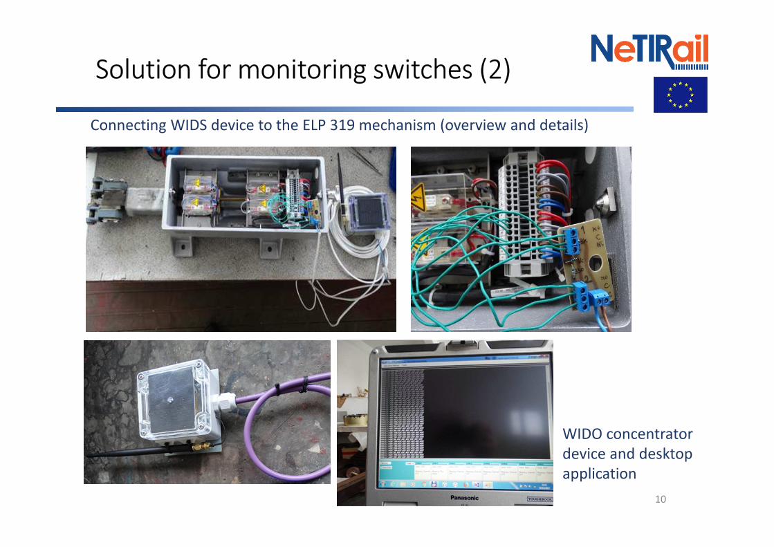
Solution for monitoring switches (2)
10
Connecting WIDS device to the ELP 319 mechanism (overview and details)
WIDO concentrator
device and desktop
application

Solution for monitoring switches (3)
Verification of the system functionality for the
ELP319:
• Random generated ELP319 operating states
• WIDS transmitted wireless messages with new changes to the terminal application
• Several times all the 5 possible states have been generated and saved in a .csv file
• No message, about status of the ELP319, was skipped
11

Thank you for your
attention!
12