update to vattenfall’s 30mwth pilot plant activities
TRANSCRIPT
© Vattenfall AB
Update to Vattenfall’s 30MWth Pilot Plant Activities
2nd Young Researchers Forum onOxyfuel Combustion R&D Programme18th – 19th September 2008
Jürgen JacobyVattenfall Research & Development [email protected]

© Vattenfall AB 22
Vattenfall in brief
• Europe’s fourth largest generator of electricity and the largest generator of heat
• Vision: To be a leading European energy company
• Main operations in Sweden, Finland, Denmark, Germany and Poland
• Electricity generation, transmission, distribution, sales and trading
• Heat generation, distribution and sales
• More than 32,000 employees
• Vattenfall AB is wholly owned by the Swedish State

© Vattenfall AB 3
Vattenfall’s generation of electricity 2004, TWh
CO2–emitting generation
CO2–neutral generation
© Vattenfall AB 4
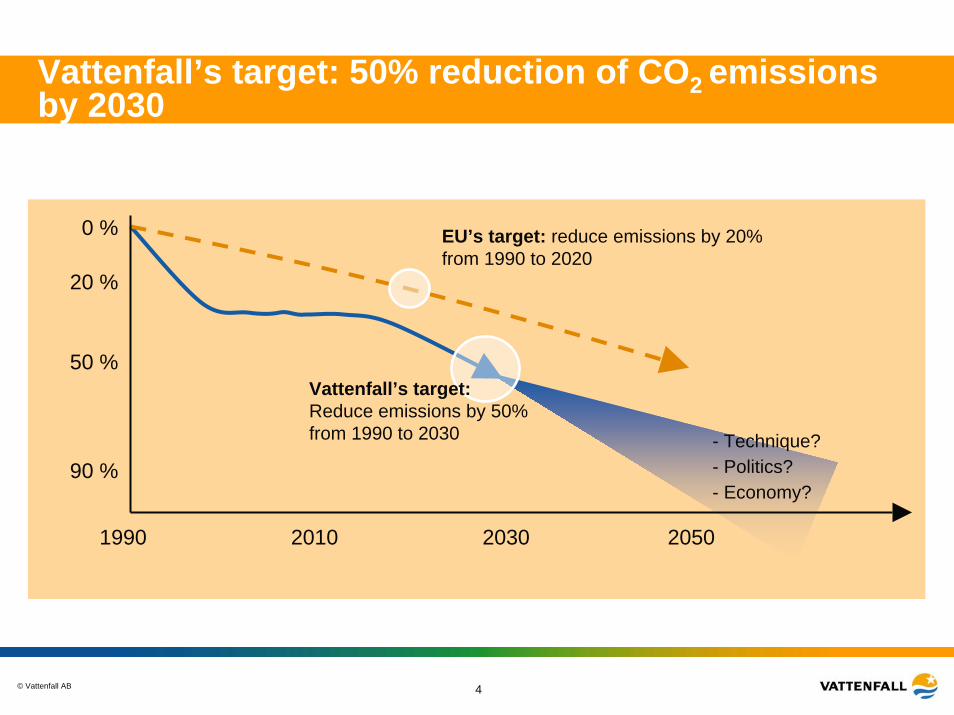
Vattenfall’s target: 50% reduction of CO2 emissions by 2030
0 %
20 %
50 %
90 %
1990 2010 2030 2050
EU’s target: reduce emissions by 20% from 1990 to 2020
Vattenfall’s target:Reduce emissions by 50% from 1990 to 2030 - Technique?
- Politics?- Economy?

© Vattenfall AB 5
Test plant
0,1-0,5 MWth< 3 Mio. €
Pilot plant
30 MWth~ 70 Mio. €
Demonstrationplant
300-600 MWth~ 400 Mio. €
Commercialplant
~ 1,000 MWth
• Research
• Basic principles
• Combustion characteristics
• Demonstration of the process chain
• Interaction of components
• Validation of basic principles and scale-up criteria
• Long term characteristics
• Non-commercial
• Verification and optimization of the component choice, the process and reduction of risks
• Must be commercially viable incl. subsidies
• Competitive in the market at that time
• No subsidies
2004 2008 2013-2015 ~2020
Time frame for the CCS project from Vattenfall

© Vattenfall AB 6
The Oxyfuel pilot plant
Furnace
FGD
ESP
CO2 plant
FGC ASU
© Vattenfall AB 7
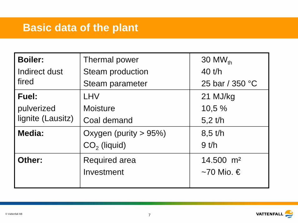
Basic data of the plant
Boiler:Indirect dust fired
Thermal powerSteam productionSteam parameter
30 MWth
40 t/h25 bar / 350 °C
Fuel: pulverized lignite (Lausitz)
LHVMoistureCoal demand
21 MJ/kg10,5 %5,2 t/h
Media: Oxygen (purity > 95%)CO2 (liquid)
8,5 t/h9 t/h
Other: Required areaInvestment
14.500 m²~70 Mio. €

© Vattenfall AB 8
Plant overview (Ref. Alstom)
Furnace
ESP FG-Condenser
CO2-ProcessFGD
Steam-HEx
Air
Burner
ASU
Start-Burner
Cold Recirculation
2. Pass
Catalysator
3. Pass
Steam-HEx
Steam-HEx
Air
Air
PulverisedCoal
SZ2
Oxygen
Steam-HEx
Nitrogen
Sealgas<1,2 bar
Sealgas6 bar
Hot Recirculation
Ash
Vent gas

© Vattenfall AB 9
Operating mode of the pilot plant
Boiler
Dry coal
Mixer
CO2 -Storage
Operating mode Flue gas quantityStart up /
conventional air operation3,5 x 100 % Oxyfuel
Transfer mode air-mode to oxyfuel mode
1,75 x 100 % Oxyfuel
Oxyfuel mode 100 %
Stac
k
Air
ca. 1/3CO2 -
liquefactionFlue gas
condenserESP FGD
ca. 2/3
Dry de-sulpherisation

© Vattenfall AB 10
Operating mode of the pilot plant
ASU
Boiler ca. 1/3
ca. 2/3 CO2 -StorageSt
ack
ca. 2/3
ca. 1/3CO2 -
liquefactionFlue gas
condenserESP FGD
Operating mode Flue gas quantityStart up /
conventional air operation3,5 x 100 % Oxyfuel
Transfer mode air-mode to oxyfuel mode
1,75 x 100 % Oxyfuel
Oxyfuel mode 100 %
Dry coal
Mixer

© Vattenfall AB 11
Operating mode of the pilot plant
Boiler
ca. 2/3 CO2 -StorageSt
ack
CO2 -liquefaction
Flue gas condenserFGDESP
Operating mode Flue gas quantityStart up /
conventional air operation3,5 x 100 % Oxyfuel
Transfer mode air-mode to oxyfuel mode
1,75 x 100 % Oxyfuel
Oxyfuel mode 100 %
Dry coalASU
ca. 1/3Mixer
© Vattenfall AB 12
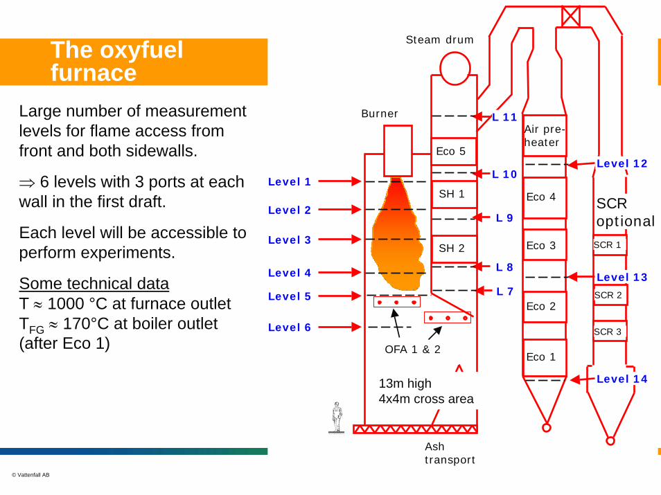
The oxyfuel furnace
Large number of measurement levels for flame access from front and both sidewalls.
⇒ 6 levels with 3 ports at each wall in the first draft.
Each level will be accessible to perform experiments.
Some technical data T ≈ 1000 °C at furnace outletTFG ≈ 170°C at boiler outlet (after Eco 1)
Eco 5
SH 1
SH 2
Air pre-heater
Eco 4
Eco 3
Eco 2
Eco 1
Level 1
Level 2
Level 3
Level 4
Level 5 L 7
L 8
L 9
L 10
L 11
Level 12
Level 13
Level 14
SCR 1
SCR 3
SCR 2
Burner
Steam drum
Ash transport
OFA 1 & 2
SCR optional
Level 6
13m high4x4m cross area

© Vattenfall AB 13
Some photos

© Vattenfall AB 14
Measurement ports in the furnace

© Vattenfall AB 15
The burner
Lignite flame
Ignition burner

© Vattenfall AB 16
Available measurement equipment
• 2 stationary hot gas multi-component FG analysers in the furnace house
(H2O, CO, CO2, O2, NO, NO2, HCl, SO2)• 2 portable cold gas multi-component FG analysers
(CO, CO2, O2, NO, NO2, SO2)• 1 portable hot gas multi-component FG analysers
(H2O, CO, CO2, O2, NO, NO2, HCl, SO2)• Gas suction probes, suction pyrometers• High temperature anemometer will be bought (delivery
problems)• Pitot-tubes and dust sampling probe• Various pumps, filters, heated tubes etc.• Ultrasonic mass flow meter, can be used for measurement of
cooling water flow.• Corrosion and deposit probesAdditional equipment can and will be applied.
© Vattenfall AB 17
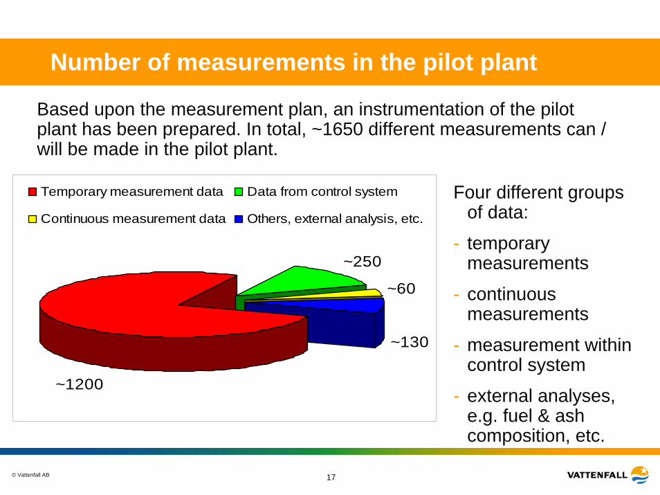
Number of measurements in the pilot plant
~130
~60
~250
~1200
Temporary measurement data Data from control system
Continuous measurement data Others, external analysis, etc.
Based upon the measurement plan, an instrumentation of the pilotplant has been prepared. In total, ~1650 different measurements can / will be made in the pilot plant.
Four different groups of data:
- temporary measurements
- continuous measurements
- measurement within control system
- external analyses, e.g. fuel & ash composition, etc.
© Vattenfall AB 18
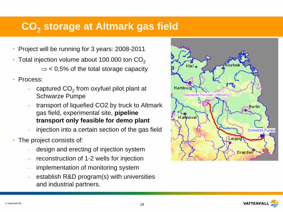
CO2 storage at Altmark gas field
• Project will be running for 3 years: 2008-2011
• Total injection volume about 100.000 ton CO2
⇒ < 0,5% of the total storage capacity
• Process: – captured CO2 from oxyfuel pilot plant at
Schwarze Pumpe– transport of liquefied CO2 by truck to Altmark
gas field, experimental site, pipeline transport only feasible for demo plant
– injection into a certain section of the gas field
• The project consists of:– design and erecting of injection system – reconstruction of 1-2 wells for injection – implementation of monitoring system– establish R&D program(s) with universities
and industrial partners.
© Vattenfall AB 19
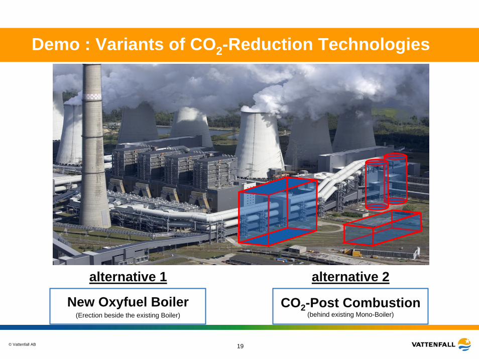
Demo : Variants of CO2-Reduction Technologies
alternative 1
New Oxyfuel Boiler(Erection beside the existing Boiler)
alternative 2
CO2-Post Combustion(behind existing Mono-Boiler)
© Vattenfall AB
http://www.vattenfall.com/ccs
Thank you !!!