update on lst-based ifr barrel upgrade roberto calabrese ferrara university workshop on ifr...
TRANSCRIPT

Update on LST-basedIFR barrel upgrade
Roberto Calabrese
Ferrara University
Workshop on IFR replacement, SLAC, 12/8/2002

Addressing the various issues
Installation issues Bill Sands
R&D issues and status Changguo Lu
Schedule and conclusions Stew Smith

Outline
IFR-LST design Modular detector construction Readout methodology Electronics Gas, HV Costs
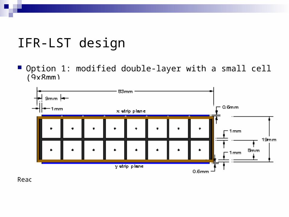
IFR-LST design
Option 1: modified double-layer with a small cell (9x8mm)
Readout of x and y coordinates from outside strips

Option 2: single-layer with a large cell (19x17 mm)
Readout of x and y coordinates from outside strips
IFR-LST design

Detector layout
We are considering 38.5 mm z-strips and 42.5 mm -strips
(2 -strips (along the wire)/LST tube)
96 z-strips for each layer, total 6912 z-strips
72 -strips for the outer layer, total 4074 -strips
10986 channels of electronics Z-strips decoupled from the chambers Chambers made with 5-7 tubes

DETECTOR LAYOUT: EXPLODEDExploded view of the composite detector chamber. The stack of layers building up the PHI strip plane is also shown exploded. The signal PCB (darker green, horizontal) goes actually on top of a portion of the strip plane with exposed strips. Signal traces on this PCB run across the strips and bring the strip signals to a connector not show in the drawing. The inner ribs are 1mm thick, while the outer ribs are 0.5mm thick. The drawing is available at www.fe.infn.it/~vito/

DETECTOR LAYOUT: ASSEMBLEDPartial view of a detector chamber made of 5 LSTs. The actual number of LSTs in a chamber, as well as the LST type (8 cells or 7 cells), varies to accommodate to the different widths of the iron gaps. The PHI strips run longitudinally. Their width is half the width of an 8 cell Iarocci tube. Their signals are brought to a PCB-mount connector, not shown here, accessible from the front. The LSTs are glued to the PHI strip plane. Carbon fiber (or steel) strips are also glued in between (some of) the LSTs of the unit, to increase the stiffness of the chamber. /

1.b Constructive details of the composite strip plane
• The composite strip plane is built as a stack of the following materials in foil:
• PET sheet, 190um thick • 50um copper foil (glued to the PET above)
machined into Z strips 37mm wide and 1.5mm apart • PET sheet, 250um thick
(It could have holes to reduce effective εr )
• FR4 sheet, 300um thick for stiffening
• 18um copper foil (glued to the PET below)• PET sheet, 50um thick
ALLOW 50um to 70um THICKNESS FOR GLUE AT INTERFACEs 1,2,3
Servizio elettronica INFN-FE http://www.fe.infn.it/electron/babar_ifr712.ppt
Modular detector construction
~ 1mm
Side facing the LSTs
Side facing the iron
2
3
1

1.c Fabrication of Z and PHI strip planes
The composite strip foils will be assembled in composite strip planes of two types:
- the Z type with:
- Plane length = detector layer’s length
- Plane width= half the detector layer’s width, for easier shipping
- Number of Z strips per plane: 96
- Single strip properties: width 36.5mm; interstrip spacing 2mm; impedance ~4
- the PHI type with:
- Plane length = detector layer’s length
- Plane width = width of LST chamber onto which it will be glued
- Number of PHI strip per plane: twice the numer of LST in the module
- Single strip properties: width 40.5mm; interstrip spacing 2mm; impedance ~3.5
The full size Z strip plane will have to be assembled at the USA assembly site.
The PHI strip planes will be glued on top of their associated chambers at the USA assembly site
Modular detector construction

IAROCCI TUBE
TUBE MATERIAL : NORYL THE TUBE IS NOT SELF SUPPORTING
30

RIB RIB MATERIAL : STEEL NUMBER OF RIBS : TO BE OPTIMIZED DEPENDING ON DETECTOR’S
EFFICIENCY AND STIFFNESS REQUIRED ASSUMING A RIB OF 1 MM THICK FOR EACH TUBE, THE TOTAL LENGTH
NEEDED IS ABOUT 8000 m

DETECTOR’S STIFFNESS: THE HELP OF THE RIBS

GLUEING – PHASE 1
THE RIB IS GLUED ON THE TUBE’S SIDE

GLUEING – PHASE 2
THE DETECTOR’S MODULE IS ASSEMBLED

GLUEING – PHASE 3
STRIPS, GROUND, SIGNAL PCB AND INSULATOR FOILS ARE ASSEMBLED THE TOTAL THICKNESS IS ABOUT 1 MM

GLUEING – PHASE 4
STRIP PLANE IS GLUED ONTO THE TUBES

DETECTOR’S VERTICAL STIFFNESS

MOUNTING AND DISMOUNTING THE DETECTOR
THE Z-STRIP PLANE GOES IN TO THE GAP; A PROPER TOOLING KEEPS IT IN SHAPE AND PLACE
THE CHAMBERS OF THE DETECTOR ARE INSERTED ONE BY ONE FROM THE BOTTOM TO THE TOP, THE NEXT SLIDING ON THE PREVIOUS ONE
EACH CHAMBER CAN BE HELD ON BOTH EDGES, WHICH ALLOWS THE LIFTING AND THE ADJUSTMENT.
WHEN THE CORNER PIECES ARE MOUNTED THE DETECTOR DISASSEMBLY IS STILL POSSIBLE AFTER THE CENTER PIECES REMOVAL; THE PROCEDURE IS THE FOLLOWING: 1) LIFTING THE UPPER CHAMBERS 2) EXTRACT THE CENTRAL CHAMBERS
3) IN THE MIDDLE OF THE GAP THERE’S THE SPACE TO LOWER OR LIFT THE OTHER CHAMBERS AND REMOVE THEM.
THE OPERATION OF ASSEMBLY AND DISASSEMBLY NEED A TOOLING FOR HOLDING AND HANDLING THE CHAMBERS OF THE DETECTOR.

Installation of the Z strip plane unbounded to the LSTs
The Z readout plane is installed first, as a whole, while the corner pieces are removed.
It leans against the iron; the FR4 makes it rigid, so that it won’t fold.
The Z strips are read out through connectors located at the backward end of the Z strip plane: in this way the connectors will not obstacle the insertion of the detector chambers from the forward end of the IFR
Z
IFR BACKWARD
IFR FORWARD
signal connectors

INSERTING THE Z-STRIP PLANE
THE Z-STRIP PLANE SLIDES INTO THE GAP A TOOLING FOR HOLDING AND MOVING THE FOIL IS NEEDED

INSERTING THE DETECTOR - 1

INSERTING THE DETECTOR - 2

EXTRACTING THE DETECTOR

THE LAYER IN PLACE

Lowering the dead spaceThe chambers will be built with different numbers of LST tubes. They will also use LSTs of
different cell numbers to better fill the iron gaps:
• 8 cells Width: 84mm + 1mm ribs
• 7 cells Width: 74mm + 1mm ribs
The drawings of the IFR iron allowed us to estimate the widths of the iron gaps for the layers that are
to be equipped with detectors.
# tubi da 8 celle #tubi da 7 celle # tot tubi #gruppi detector width[mm] gap width[mm] diff.[mm]layer 1 22 0 22 4 1870 1909 39layer 2 21 2 23 4 1935 1978 43layer 3 20 4 24 4 2000 2042 42layer 4 20 5 25 4 2075 2105 30layer 6 25 1 26 5 2200 2232 32layer 8 22 6 28 5 2320 2359 39layer 10 28 1 29 5 2455 2486 31layer 12 27 4 31 5 2595 2629 34layer 14 32 0 32 5 2720 2751 31layer 16 31 3 34 6 2860 2896 36layer 17 30 5 35 6 2925 2956 31layer 18 33 4 37 6 3105 3143 38

1.g1 details of strip signal collection PCB and cabling
Modular detector construction
A
A
E
D
C
B
A) strip foil (190um PET foil facing DOWN)
B) 500um mono-layer PCB (on FR4)
with holes, for soldering traces to strips, and
signal traces running toward the connector
C) 200um mono-layer PCB (on FR4) : ground plane
for signal traces: solid copper facing up
D) composite insulating foil for the detector’s strips
readout plane
E) solid copper foil (50um PET, copper foil
facing DOWN)
ddrawings by V. Carassiti: www.fe.infn.it/~vitodrawings by V. Carassiti: www.fe.infn.it/~vito

1.g2 details of strip signal collection PCB and cabling
Modular detector construction
The long PCB used to collect signals from the Z strips could be made in Kapton (which was quoted us
700Euro each) or could be home-made in 2 pieces of FR4 with signal traces obtained by machining the
solid copper surface (100 Euro/m2 ). The 2 pieces would have to be soldered together.
Then they would have to be soldered to a third PCB that routes the signals to a suitable connector like the
Robinson Nugent P50E-034P1-SR1-TG
The shorter PCB used to collect signals from the PHI strips can be fabricated by the standard etching
techniques. It also mounts the right angle PCB connector Robinson Nugent P50E-034P1-SR1-TG .
The cable chosen is the Amphenol 425 3016 034, “microribbon twist&flat” cable, with a 0.025” pitch,
higly flame retardant and halogen free.
It will be fitted with an header Robinson Nugent P25E-034S-TG. The cable cost is about 14 Euro/m.
Around 200 such flat cables should fit into a 2” x 4” cable conduit

Readout methodology
Only digital readout of strips
Time measurements could be implemented: OR of 16 discriminated pulses Time resolution about 16 ns ( using BaBar reference clock) Implemented with FPGA

Front end electronics design: block diagram of the new 64 channel FEC
64x Amplifier-Discriminator11
us D
igit
al O
neSh
ot
Shift/LoadCk_Chain Data Out
SHIFT REGISTER
64 x
Threshold
12us
Dig
ital
One
Shot
11us
Dig
ital
One
Shot
12us
Dig
ital
One
Shot
Shift/Load4 x
4 x4 x
Implemented in a single high performance FPGA
(Field Programmable Gate Array)
from
backplane
to
backplanefrom
backplane
4 x input connectors for microribbon cable
Estimated board power consumption:
16W
A VHDL model of the logic architecture
implemented in the FPGA is available
( link:
www.fe.infn.it/electron/babar_ifr.htm )

Front end electronics design: Schematic of the front end based on Off-The-Shelf components
Power dissipation: 250mW

Front end electronics design: analog simulations
Simulation of the amplifier/discriminator
output from a 4pC input signal
(0.1mA * 40ns)
Comparator threshold = 50mV
dielectric thickness 0.75mm
a) dielectric FOAM (εr=1)
b) dielectric PTE (εr=3.3)
c) dielectric FR4 (εr=4.8)
a) b)
c)
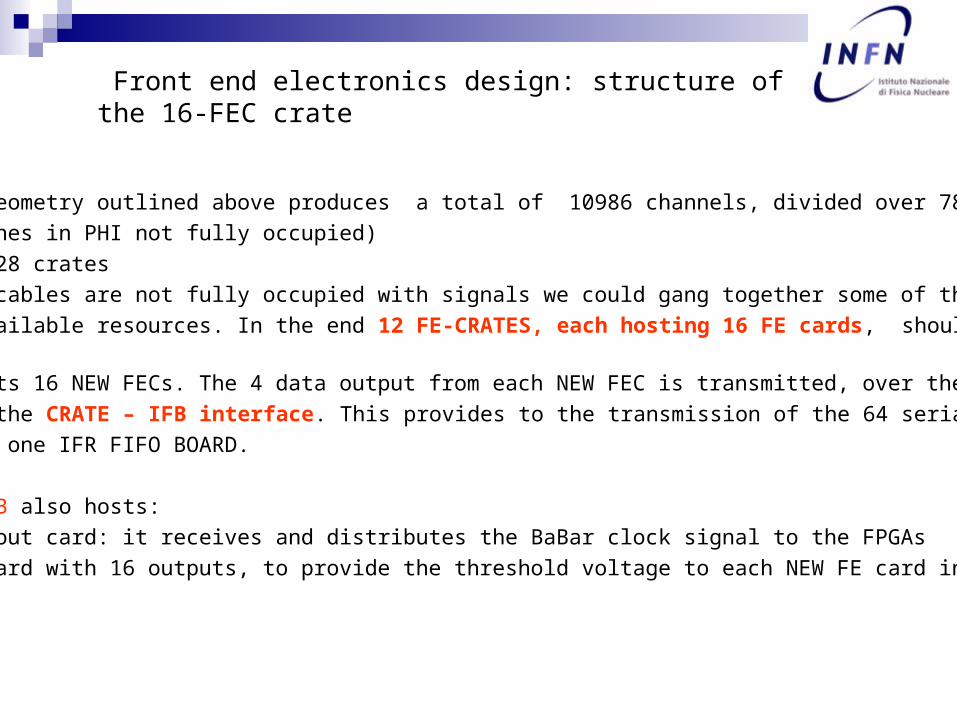
Front end electronics design: structure of the 16-FEC crate
The detector geometry outlined above produces a total of 10986 channels, divided over 786 cables
(most of the ones in PHI not fully occupied)
786 / 64 = 12,28 crates
Since the PHI cables are not fully occupied with signals we could gang together some of them, to better
exploit the available resources. In the end 12 FE-CRATES, each hosting 16 FE cards, should be sufficient.
Each crate hosts 16 NEW FECs. The 4 data output from each NEW FEC is transmitted, over the CRATE
backplane, to the CRATE – IFB interface. This provides to the transmission of the 64 serial data
streams toward one IFR FIFO BOARD.
The CRATE – IFB also hosts:
-one Clock fanout card: it receives and distributes the BaBar clock signal to the FPGAs
-one DAC/ADC card with 16 outputs, to provide the threshold voltage to each NEW FE card independently.

Update on HV cables
The HV cable is now defined:
the KERPEN code 76130005 is a 37 conductor HV cable, compliant to SLAC safety standards and particularly suited for this application, since, with the detector segmentation shown above, the number of HV channels required per layer reaches just the value of 37.
We have then one cable per layer, 12 per sextant. Each cable has a cross section area of about 1.3cm2 (1.3cm in diameter)

Gas system
Mass flow control system.
New mixing station in existing gas shack. Main gas transport pipe system.
It should be possible to use existing pipes (spares). Final gas distribution and bubbling system.
The current bubbler boxes can be reused.
We assume all the tubes in a layer with a single in/out. Safe gas mixture, like Ar/Iso/CO2 (2.5/9.5/88) (SLD)

Individual HV connections N. 4152
HV distributed channels N. 1038
Worste case rate (2 Hz/cm2) Hz 6400
Max chamber current A 0.64
Typical rate (0.2 Hz/cm2) Hz 640
Max chamber current A 0.06
HV system
Each chamber is connected through individual conductors up to the distribution crates. The HV system has to provide:
• Regulated HV up to 5 kV
• Current monitoring
• Overcurrent protection
Number of channels and maximum current per channel:
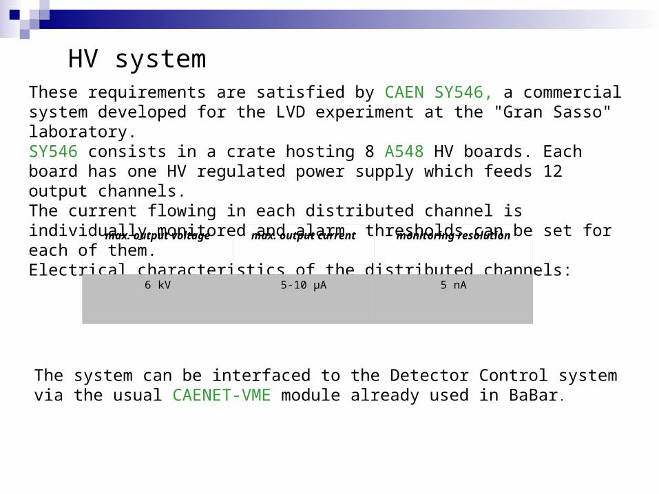
These requirements are satisfied by CAEN SY546, a commercial system developed for the LVD experiment at the "Gran Sasso" laboratory.SY546 consists in a crate hosting 8 A548 HV boards. Each board has one HV regulated power supply which feeds 12 output channels. The current flowing in each distributed channel is individually monitored and alarm thresholds can be set for each of them. Electrical characteristics of the distributed channels:
max. output voltage max. output current monitoring resolution
6 kV 5-10 µA 5 nA
The system can be interfaced to the Detector Control system via the usual CAENET-VME module already used in BaBar.
HV system

Update on cost estimates: assumptions
• Double layer LST; 8 cells and 7 cells types; each layer with a separate HV
• 96 strip (36mm strips) in the Z direction; 2 strip per LST in the PHI direction
• Z strip plane installed and readout as a whole; readout from backward side of IFR
• Modular detector construction; readout from the forward side of the subdetectors
• 12 active layers
An EXCEL spreadsheet is available to help determining the costs of the proposed apparatus, “numerologia712.xls” ( link: www.fe.infn.it/electron/babar_ifr.htm)

Update on cost estimates: assumptions
Total number of 8-cell LSTs: 1866
Total number of 7-cell LSTs: 210
Total number of HV channels: 4152
Total number of Z strips : 6912
Total number of PHI strips : 4074
Total number of signals: 10986
Total number of microribbon flat cables: 786
Total number of FE CRATEs (16 NEW FE cards per CRATE): 12
Total number of NEW FE CARDS: 192 (12288 channels)
Total area of Z /PHI strip plane [m²]: 1290.3

Update on cost estimates
Tubes: 30 K$ (setup) 405 K$ ( 195 $/tube x 2076 double layer tubes)Total cost tubes 435K$
(using single layer tube this cost would be about 300K$)
Strip readout planes215 m2/sextant x 6 sextant x 70 $/m2 = 90 K$
Signal collection (PCB’s) inside iron 18 K$Total cost readout planes 108 K$
Grand total chambers 543K$ (double layers); 408K$ (single layers)

Update on cost estimates
Strip planes (includes glueing the ribs aside the LSTs)
Total cost of Z /PHI readout strip plane [Euro]: 90318
of which labor is (80%) [Euro]: 72255
areas in square meters costs in euros:area of detectors: area od readout planes: cost of readout planes:per sextant per sextant per sextant
layer 1 6.92 13.84 969layer 2 7.16 14.32 1002layer 3 7.40 14.80 1036layer 4 7.68 15.36 1075layer 6 8.14 16.28 1140layer 8 8.58 17.17 1202layer 10 9.08 18.17 1272layer 12 9.60 19.20 1344layer 14 10.06 20.13 1409layer 16 10.58 21.16 1481layer 17 10.82 21.65 1515layer 18 11.49 22.98 1608
area Z/PHI per sextant: 215.04cost of COMPOSITE readout planes [Euro/square meter] 70 total per sextant: 15053(300um FR4 foil added)vedi CERN stock 12(steel ribs added)
total area: 1290.26 total: 90318of which labor is: (80%) 72254.78

Update on cost estimates
PCBs for strip signal collection
Total cost of Z strip PCBs [Euro]: 13320 of which labor is [Euro]: 9990
Total cost of PHI strip PCBs [Euro]: 4425 of which labor is [Euro]: 2212.5
Zstrip PCB width [mm]: 250 PHI strip PCB width [mm] 100# Zstrip PCB / layer 2 Avg PHI strip PCB length [mm] 500Total Z strip PCB area (meter**2) 133.2 #PHI PCBs per sextant: 59
#PHI PCBs: 354cost of signal PCB: Euro/m**2 100 Tot PHI strip PCB area (meter**2) 18( if made in-house ) cost of signal PCB: Euro/m**2 250Total Z strip PCB cost: 13320 Total PHI strip PCB cost: 4425of which labor is: (75%) 9990 of which labor is: (50%) 2212.5

Update on cost estimates
HV cables including soldering of terminations
Total cost of KERPEN HV cable [Euro]: 2695
Total cost of GND return LV cable [Euro]: 7473
Total cost of terminating KERPEN HV cable [Euro]: 14947 of which labor is [Euro]: 12456
Total cost of terminating LV cable [Euro]: 10795 of which labor is [Euro]: 8304#tot canale HV for double layer tubes 4152#of KERPEN HV CABLES (37 conductors) 72ONE KERPEN CABLE per LAYERtotal length of KERPEN cable [m] 864Unit cost for KERPEN cable [Euro per KM] 3120Total cost for KERPEN cable [Euro] 2695.68length of KERPEN cable per layer [m] 12
tot Length of LV wire [m] 49824unit cost of LV wire [Euro/m] 0.15tot cost of LV wire [Euro] 7473.6
tube side #banana plugs needed for HV: 4152distrib side#banana plugs needed for HV: 4152
unit cost of HV banana plugs(Euro): 0.3labor cost soldering one HV plug [euro]: 1.5total cost of HV banana plugs(Euro): 14947.2of which labor is: 12456
tube side #banana plugs needed for LV: 4152distrib side#banana plugs needed for LV: 4152
unit cost of LV banana plugs(Euro): 0.3labor cost soldering one LV plug [euro]: 1total cost of LV banana plugs(Euro): 10795.2of which labor is: 8304

Update on cost estimates
Signal cables including crimping of headers
Total cost of microribbon flat cables [Euro]: 132048
Total cost of microribbon connectors [Euro]: 14148
add labor for crimping [Euro]: 6288#connettori per estrazione segnali Z (per layer): 6#connettori per estrazione segnali Z (per sextant): 72 #tot microribbon cables segnali Z (per layer): 72
#tot microribbon cables per estrazione segnali Z : 432#tot connettori PCB per estrazione segnali Z : 864#tot header per microribbon per estrazione segnali Z : 864 #tot microribbon cables segnali PHI: 354
#totale microribbon cables 786#lungh cavo segnale [m]: 12
#connettori per estrazione segnali PHI (per sextant): 59 #tot lungh cavo segnale [m]: 9432
#tot connettori PCB per estrazione segnali PHI : 708 #costo unit. Microribbon cable amphenol [Euro/m]: 14#tot header per microribbon per estrazione segnali PHI : 708 #costo tot.Microribbon cable amphenol [Euro]: 132048
#tot connettori PCB per microribbon flat : 1572 #total costo PCB conn.[euro]: 5030.4#tot header per microribbon flat : 1572 #total costo header flat[euro]: 9117.6
costo unitario connettore PCB per microribbon[euro]: 3.2 #totale connettori segnale 14148P50E-034P1-SR1-TG Robison Nugent
costo header flat per microribbon[euro]: 5.8 crimping labor [euro/cable]: 8P25E-034S-TG Robison Nugent total crimping labor[euro]: 6288
grand total cable preparation (connectors,cables,labor) 152484
Update on cost estimates
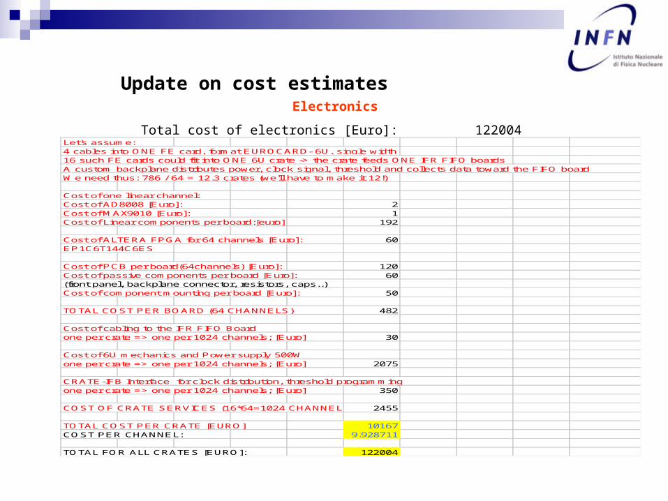
Electronics
Total cost of electronics [Euro]: 122004 Let's assume: 4 cables into ONE FE card, format EUROCARD- 6U, single width 16 such FE cards could fit into ONE 6U crate -> the crate feeds ONE IFR FIFO boardsA custom backplane distributes power, clock signal, threshold and collects data toward the FIFO boardWe need thus: 786 / 64 = 12.3 crates (we'll have to make it 12!)
Cost of one linear channel:Cost of AD8008 [Euro]: 2Cost of MAX9010 [Euro]: 1Cost of Linear components per board:[euro] 192
Cost of ALTERA FPGA for 64 channels [Euro]: 60EP1C6T144C6ES
Cost of PCB per board(64channels) [Euro]: 120Cost of passive components per board [Euro]: 60(front panel, backplane connector, resistors, caps..)Cost of component mounting per board [Euro]: 50
TOTAL COST PER BOARD (64 CHANNELS) 482
Cost of cabling to the IFR FIFO Board one per crate => one per 1024 channels; [Euro] 30
Cost of 6U mechanics and Power supply 500Wone per crate => one per 1024 channels; [Euro] 2075
CRATE-IFB Interface for clock distribution, threshold programmingone per crate => one per 1024 channels; [Euro] 350
COST OF CRATE SERVICES (16*64=1024 CHANNELS) 2455
TOTAL COST PER CRATE [EURO] 10167COST PER CHANNEL: 9.928711
TOTAL FOR ALL CRATES [EURO]: 122004

.
TDC system: 20 K$
HV system11 SY546 systems with 87 A548 12 ch Active boards
SY546 Main: 3300 $A548 12 CH Active: 1400 $
Tot: 3300 x 11+ 1400 x 87= 158100 $
11 Distribution boxes = 10000 $
Total HV system : 168 K$
Update on cost estimates

Update on cost estimates
Total cost gas system 50 K$ DAQ, cooling no expected cost
Grand total detector 955 K$ 1090 K$