update of technical basis for inspection of alloy 600 pwr
TRANSCRIPT
Update of Technical Basis for Inspection of Alloy 600 PWR Reactor Vessel Top Head
NozzlesNRC Public Meeting, Rockville, MD
G S ( )G. White, K. Fuhr, K. Schmitt (Dominion Engineering, Inc.)C. Harrington (EPRI)October 31, 2014,

Purpose
• Fulfill EPRI MRP commitment to provide NRC an update on the implications of plant experience for the inspection basis for PWR top heads
• Provide recommendations• Provide recommendations– Allow two-cycle volumetric or surface exam interval for
cold heads with previously detected PWSCC– Maintain current visual exam intervals
© 2014 Electric Power Research Institute, Inc. All rights reserved. 2

Topics MRP-395 was published on September 30, 2014, and is freely downloadable at www.epri.com:M t i l R li bilit P R l ti f T h i l B i
• Introduction
Materials Reliability Program: Reevaluation of Technical Basis for Inspection of Alloy 600 PWR Reactor Vessel Top Head Nozzles (MRP-395). EPRI, Palo Alto, CA: 2014. 3002003099.
– Status of U.S. Fleet• Original Technical Basis for ASME Code Case N-729-1• Updated Technical Basis (MRP-395)
– Assessment of Plant ExperienceDeterministic Analyses– Deterministic Analyses
– Probabilistic Analyses– Assessment of Concern for Boric Acid CorrosionAssessment of Concern for Boric Acid Corrosion– Conclusions
• Recommendations
© 2014 Electric Power Research Institute, Inc. All rights reserved. 3

Introduction
© 2014 Electric Power Research Institute, Inc. All rights reserved. 4

Inspection Results SummaryTimeline
• First leak on CRDM penetration at Bugey 3 in France in 1991• Between 1991 and 2000 surface examinations of the CRDM nozzle ID• Between 1991 and 2000, surface examinations of the CRDM nozzle ID
were performed at several U.S. PWRs– A 43% through-wall axial flaw was detected
I N b 2000 l k d t PWSCC di d f th fi t• In November 2000, leaks due to PWSCC were discovered for the first time in the U.S. on reactor pressure vessel head (RPVH) penetrations
• In Spring 2001, circumferential flaws discovered above the J-groove ld th t id f f t l ki lweld on the outside surface of two leaking nozzles
• In Spring 2002, CRDM nozzle leaks were detected on one head that led to significant boric acid wastage of the low-alloy steel top head
t i l i i l t f th h d i 2003material requiring replacement of the head in 2003• NRC Order EA-03-009, dated February 11, 2003
– Established High, Moderate, and Low susceptibility categories based on
© 2014 Electric Power Research Institute, Inc. All rights reserved. 5
effective degradation years (EDYs)**measure of cumulative operating time normalized to a head temperature of 600°F using the temperature dependence for PWSCC crack initiation

Inspection Results SummaryTimeline (cont’d)( )
• By December 2003, all the original heads in service were inspected by bare metal visual examination and/or volumetric/surface NDEbare metal visual examination and/or volumetric/surface NDE techniques
• NRC First Revised Order EA-03-009, dated February 20, 2004• By Fall 2005 all 46 plants with > 8 EDYs completed baseline• By Fall 2005, all 46 plants with > 8 EDYs completed baseline
volumetric/surface exams or head replacement• By February 2008, all the original heads in service were inspected by
volumetric/surface NDE techniquesvolumetric/surface NDE techniques• December 31, 2008, Implementation Date for ASME Code Case
N-729-1– Established requirement for repeat volumetric/surface exams based on Re-
Inspection Years (RIYs)*• First repeat volumetric/surface exams in heads operating at Tcold (i.e.,
ld h d ) ll t t d i 2011
© 2014 Electric Power Research Institute, Inc. All rights reserved. 6
cold heads) generally started in 2011*measure of operating time normalized to a head temperature of 600°F using the temperature dependence of the PWSCC crack growth rate

IntroductionTypes of PWR RV Head Nozzle PWSCCyp
© 2014 Electric Power Research Institute, Inc. All rights reserved. 7

IntroductionU.S. Fleet Status – Summaryy
• 63 heads with Alloy 600 nozzles have been inspected by non-visual NDEvisual NDE
• 24 heads with Alloy 600 nozzles remain in-service– 1822 CRDM/CEDM nozzles remain in-service and 46 other
J-groove top head nozzles– 19 of these heads operate at Tcold (1483 of the Alloy 600 J-
groove nozzles)– There are plans for replacement or peening mitigation for
some of the heads now in service• Seven heads remaining in-service have detected PWSCCg
– Five of these heads operate at Tcold• 41 heads with replacement materials (Alloy 690 nozzles and
Alloy 52/152 attachment welds) are now in service
© 2014 Electric Power Research Institute, Inc. All rights reserved. 8
Alloy 52/152 attachment welds) are now in service
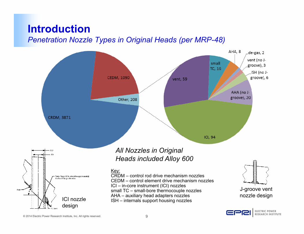
IntroductionPenetration Nozzle Types in Original Heads (per MRP-48)yp g (p )
All Nozzles in Original Heads included Alloy 600
Key:CRDM – control rod drive mechanism nozzlesCEDM – control element drive mechanism nozzlesICI – in-core instrument (ICI) nozzlessmall TC – small-bore thermocouple nozzles J-groove vent
y
© 2014 Electric Power Research Institute, Inc. All rights reserved. 9
small TC – small-bore thermocouple nozzlesAHA – auxiliary head adapters nozzlesISH – internals support housing nozzlesICI nozzle
design
J g oo e e tnozzle design

IntroductionNozzle Types in Heads Still in Service with Alloy 600 Nozzlesyp y
vent (no J-groove), 2
AHA, 8
CRDM, 1696
CEDM, 126AHA (no J-groove), 20
Other, 68
All Nozzles in Original Heads included Alloy 600
ICI, 16
vent, 22
y
© 2014 Electric Power Research Institute, Inc. All rights reserved. 10

IntroductionU.S. Fleet Status – Number of Nozzles In-Service
10
5000
t of Y
ear
Cold Heads (at Tcold Temperature)
Non-Cold Heads
6
8
ber
of H
eads
3000
4000
in S
ervi
ce a
t Sta
r
2
4
Num
b
2000
Noz
zles
Rem
aini
ng
02000 2001 2002 2003 2004 2005 2006 2007 2008 2009 2010 2011 2012 2013 2014 2015 2016 2017
Replacement Date
1000
Allo
y 60
0 N
© 2014 Electric Power Research Institute, Inc. All rights reserved. 11
02000 2001 2002 2003 2004 2005 2006 2007 2008 2009 2010 2011 2012 2013 2014 2015 2016 2017 2018
Year

Original Technical Basisfor ASME Code Case N 729 1for ASME Code Case N-729-1
© 2014 Electric Power Research Institute, Inc. All rights reserved. 12

Technical Basis for N-729-1Introduction – Summary of Current Inspection Requirementsy p q
• The current inspection requirements are defined by ASME Code Case N-729-1, which is mandated by NRC subject to conditions in 10 CFR 50.55a(g)(6)(ii)(D)
• Periodic volumetric or surface exams for indications of cracking:– Every 8 calendar years or before Reinspection Years (RIY) = 2.25
C ld h d ll 4 5 18 th f l l• Cold heads: usually every 4 or 5 18-month fuel cycles• Non-cold heads: usually every one or two fuel cycles
– If PWSCC has previously been detected, NRC condition requires the exam every refueling outage (rather than the N-729-1 requirement of every other refueling outage, if permitted by RIY 2 25)RIY = 2.25)
• Periodic visual exams of outer surface of head for evidence of pressure boundary leakage:
– Direct visual exam (VE) of the entire outer surface of the head, including essentially 100%Direct visual exam (VE) of the entire outer surface of the head, including essentially 100% of the intersection of each nozzle with the head, every RFO
– Except if EDY < 8 and no flaws unacceptable for continued service have been detected, the VE interval is every 3rd refueling outage or 5 calendar years, whichever is less
• An IWA-2212 VT-2 visual examination of the head is performed under the insulation
© 2014 Electric Power Research Institute, Inc. All rights reserved. 13
An IWA 2212 VT 2 visual examination of the head is performed under the insulation through multiple access points in outages that the VE is not completed

Technical Basis for N-729-1Introduction – Technical Basis Documents and Public Meetingsg
• The original technical basis for ASME Code Case N-729-1 was developed by EPRI MRP in 2001-04:– MRP-117: Technical Basis Summary– MRP-110: Top Level Safety Assessment Report– MRP-105: Probabilistic Assessments– MRP-95R1: Basis for Volumetric or Surface Inspection Coverage– MRP-103 and MRP-104: Supporting Safety Assessments– MRP-48: Tabulations of Head-Specific Info
MRP 55 d MRP 115 PWSCC C k G th R t St di– MRP-55 and MRP-115: PWSCC Crack Growth Rate Studies– EPRI 1007842: Visual examinations for leakage– MRP-89: Demonstrations of vendor equipment and procedures for NDE
• The technical basis was discussed at a series of NRC public meetings:• The technical basis was discussed at a series of NRC public meetings:– June 12, 2003– March 2, 2004
April 14 2004
© 2014 Electric Power Research Institute, Inc. All rights reserved. 14
– April 14, 2004– September 8, 2004

Technical Basis for N-729-1MRP-110 Table of Contents
1. Introduction and Summary2. Failure Mode and Effect Analysis (FMEA)y ( )3. Summary of Flaw and Wastage Tolerance Calculations4. Inspection Experience5. Welding Residual Stress and Stress Intensity Factor Calculationsg y6. Nozzle Ejection Evaluations7. Head Wastage Evaluations8. Consequential Damage Assessment9. Inspection Capabilities10. Replacement Head Materials
A. Head Maps and Penetration DesignsB. FMEA Failure-Path Disposition TableC. FMEA Technical DiscussionsD Fl d W t T l C l l ti
© 2014 Electric Power Research Institute, Inc. All rights reserved. 15
D. Flaw and Wastage Tolerance CalculationsE. Modeling of Head Wastage Process

Technical Basis for N-729-12001-04 Safety Assessment Processy
Nozzle Ejection EvaluationsAssessment of Potentialfor Lack of Weld Fusion /PWSCC at Fusion Line
DeterministicAssessmentfor Ejection
Assessment ofAllowable Circ
Crack Size
DRAFT, February 17, 2003Reg. Guide
1.174
TechnicalBasis: Nozzle
Ejection
PotentialRCS WaterChemistry
EffectsAssessment of
Compilation ofMaterial
Processing &FabricationPractices
Assessmentof ExistingData for
A690/152/52
AdditionalTesting for
A690/152/52
ConsequentialDamage
Assessments
Increase inCore Damage
Frequency(CDF)
Prob. RiskAssessmentfor Ejection
(PFM Model)
Crack Size
Weibull StatisticalAssessments of
Probability ofCracking &Leakage
WeibullSlope Basedon Data for
SimilarApplications
TechnicalBasis: EDYSusceptibility
Model
j
DetectabilityLimits for
DetectabilityLimits forCracking
(ET, UT, PT)
Processing &FabricationDifferences
ActivationUS Experiencewith PWSCC of
InspectionDetectability
TechnicalBasis for
A690, 152, 52
Limits forLeakage
Crack GrowthRates for Alloy
Crack GrowthRates for Alloy
Crack GrowthRate Expert
Crack Growth Rate (CGR) Evaluations Stress Intensity Factor (K) Evaluations
FractureMechanics
A t
Welding ResidualStress Finite
El t A l
Effect ofGeometry &
M t i l
Benchmarking/Calibration ofPFM Model
Energy forCrack
Initiation
Plant and LabExperience
with PWSCCof A600
RVH NozzlesInt’l Experiencewith PWSCC ofRVH Nozzles
Wastage EvaluationsSafety
Assessment(SA) Report
Failure Modes& EffectsAnalysis(FMEA)
TechnicalBasis: Head
ProbabilisticRisk
Assessmentfor Wastage
Existing BACTest Data
Plant
DetectabilityRequirements
Establishmentof BAC
WastageRates
A Definition ofSusceptibilityEDY Groups
Rates for Alloy600 (MRP-55)
Rates for Alloy182, 82 Welds
Rate ExpertPanel Assessments
of Driving KsElement Analyses
(FEA)Material
Strength on Ks
B
NDEInspectionBasis: Head
Wastage
DeterministicAssessmentfor Wastage
PlannedAdditional
BAC Testing
aExperiencewith Boric
Acid Corrosion(BAC)
AllowableWastage
MaintainingCode Stresses
BAC WastageReview Panel
Loose Parts EvaluationsA
InspectionIntervals
MRP
PlantsNDE Vendors
Expert Panels
© 2014 Electric Power Research Institute, Inc. All rights reserved. 16
Other FMEAFailure Path
Assessments
Assessment ofLoose PartsGeneration
Assessment ofLoose Parts
ConsequencesB
ASMENDE Vendors
NRC Regs.

Technical Basis for N-729-1MRP-110 FMEA Failure Path Flow Chart
CoreDamage
FailureLevel 1
FailureLevel 2
Small-BreakLOCA
Medium-BreakLOCA
Consequential Damage(Damage to Other
Mechanisms or Nozzles,Cut Cables, etc.)
PreventControl Rod
Drop
Large EarlyRelease Color Key:
Not Credible
Not Actionable
ActionableDamage toBottomReactor
Vessel Area
Damage toFuel Pins
Damage toSteam
Generator Tubesor Tubesheet
Other LooseParts Damage
ContainmentBuildingLeakage
Accident Events
Boric Acid CorrosionLoose Parts Release
PreventMultiple
Control RodDrops
F
Large-BreakLOCA
FailureLevel 4
FailureLevel 3
NozzleEjection
CladdingBlowout
Release ofCaptured
Loose Part
Circ Crack >~95%of Nozzle CrossSection Above orNear Top of Weld
Wastage CavityUncovering
Large CladdingArea
Thru-Wall CircCrack 100%
Around NozzleBelow Weld
Intersecting Groupof Axial and CircThru-Wall Cracks
Below Weld
ASME CodeStress
MarginsExceeded
Very Large (Critical Size)Loss of Weld Bond
Between Nozzle & Weld
Head LowAlloy Steel
Rupture
Release ofNon-captured
Loose Part
Flaws in theVessel
Cladding
Aging Degradation
Boric Acid CorrosionRCS Leakage
Plant OperationHead Fabrication
F
FailureLevel 6
FailureLevel 5
Significant HeadWastage in
Annulus, at Clad,or on Head Top
Initiation of orBranching to
OD Circ CrackAbove Weld
Circ Crack Growthand Possibly
Coalescence ofMultiple Circs
Incipient HeadWastage
Deep Down inAnnulus
Turning of Circ-Axial Weld Flaw
into Alloy 600Nozzle Tube
Leakage fromAbove RPV Head
Pre-ExistingBoron Depositson Top Head
Surface
May ImpactLeakage
Detectability
PotentialChange in
Crack Direction
A
GH
J
RPV HeadLeak
FailureLevel 7
FailureLevel 8
Growth/Coalescenceof Circ-AxialWeld Flaw
Growth/Coalescence
of Radial-AxialWeld Flaw
Growth/Coalescenceof ID Axial Flaw (inDepth and Possibly
Upward)
Growth/Coalescence ofOD Axial Flaw
Upward
Growth/Coalescence of
Below WeldCirc Flaw
C k G th
Crack GrowthDriven by
EnvironmentalFatigue
Growth/Coalescence
of Lack ofFusion Areas
Surface Defects inNozzle Tube from
Processing/Fabrication/Welding
VolumetricDefects in NozzleTube from Mat’l
Processing
Coalescence ofMultiple Flaws
B
DWeld Hot Cracking
and Other WeldFabrication Defects
A Growth/Branching (to
Axial) of BelowWeld Circ Flaw
GH
J
GH
J
GH
J
GHIJ
GHIJ
GHIJ
FailureLevel 9
Initiation ofDetectable ID
Circ FlawAbove Weld
Initiation ofDetectable ID
Axial Flaw
Initiation ofDetectable OD
Axial FlawBelow Weld
Initiation ofDetectable ID
Circ FlawBelow Weld
Initiation ofDetectable OD
Circ FlawBelow Weld
Initiation ofDetectable
Circ-Axial Weldor Butter Flaw
Initiation ofDetectable Radial-
Axial Weld or ButterFlaw
FailureLevel 10
Crack GrowthDriven by Stress
Corrosion Cracking
ThermalFatigue
Fatigue fromNormal
OperatingTransients
High-Cycle
Fatigue
WeldingResidualStresses
PressureStresses
FabricationResidualStresses
Lack of Fusion(Weld to
Head) fromFabrication
Off WaterChemistry
Conditions in PastIncreased Potential for SCC Initiation for Alloy 600 Nozzle Tube
Increased Potential for SCCInitiation for 182 Weld and
Buttering
A
C
C
D
Low Temp.Crack
Propagation
Lack of Fusion(Tube to
Weld) fromFabrication
D
E
© 2014 Electric Power Research Institute, Inc. All rights reserved. 17
FailureLevel 11
Natural Circ.Inside the
Nozzle Tube
Mech.Vibration
Number ofOutages and
Trips
Nozzle RollStraighteningDuring Mat’lProcessing
Surface ColdWorking from
Machining
Mat’l Propertiesdue to ThermalProcessing of
Base Mat’l
Grinding ofWeld During
HeadFabrication
Grinding ofNozzle Tube IDor OD DuringInstallation
Contaminants fromFabrication
SurfaceContaminants onNozzle Tube ID &OD During Install
NozzleStraightening
AfterInstallation
B
ResinIntrusions
PreviousChemistry
Excursions/Contamination
Startup WaterChemistry (Hot
Functionals)
E

Technical Basis for N-729-1FMEA Conclusions
• The FMEA results:fi th t l j ti d h d t th t j– confirm that nozzle ejection and head wastage are the two major
potential safety concerns– help define the inspection capabilities that are needed to detect
d d ti i ti l f hidegradation in a timely fashion
• The generation of loose parts is a potential third concern that helps to set the required inspection area for periodic p q p pnon-visual inspections
• The FMEA results were used in combination with the ll f t t lt t t i toverall safety assessment results to set appropriate
inspection requirements to maintain substantial margin against safety-significant failures
© 2014 Electric Power Research Institute, Inc. All rights reserved. 18

Technical Basis for N-729-1Flaw Tolerance
• Top heads and their nozzles are highly flaw tolerant
C iti l i l k l th i h t– Critical axial crack length is much greater than the height of the nozzle region subject to welding residual stresses
– Critical length of through-wall circ flaw in– Critical length of through-wall circ flaw in tube is a large fraction of the circumference
– FEA calculations show that ASME Code primary membrane and membrane plus Table 3-1 of MRP-110:
Critical Flaw Angles for Through-Wall Circ Nozzle Flawsp y pbending stress requirements are still met assuming a substantial volume of low-alloy steel head material is lost
NozzleType
NozzleGeometry
OD(in)
FlawAngle θ
for P flow = 2500 psi
(deg)
FlawAngle θ
for P flow = 6750 psi
(deg)
Limiting Nozzle of
Type330 285M Westinghouse 4 000
Critical Flaw Angles for Through Wall Circ Nozzle Flaws
329 281B&W CRDM 4.002 328 281 CE CEDM Type 1a 4.050 331 288CE CEDM Type 1b 4.050 331 288CE CEDM Type 2 3.850 323 268CE CEDM Type 3/4 3.495 318 254 CE CEDM Type 5 4 275 334 293
CR
DM
CED
M
gCRDM 4.000
284°330°Circ. through-wall flaw
5.3inches
14.3inches
Axial through-wall flaw in nozzle above J-weld
6750 psi2500 psi
284°330°Circ. through-wall flaw
5.3inches
14.3inches
Axial through-wall flaw in nozzle above J-weld
6750 psi2500 psi
Typical Results for CRDM Nozzle
© 2014 Electric Power Research Institute, Inc. All rights reserved. 19
CE CEDM Type 5 4.275 334 293CE ICI Type 1 5.563 293 195 CE ICI Type 2 4.500 309 232CE ICI Type 3 6.625 313 244
ICI
271°327°Lack of fusion between nozzle and weld
284330above J-weld
271°327°Lack of fusion between nozzle and weld
284330above J-weld

Technical Basis for N-729-1MRP-105 Probabilistic Analysesy
• Acceptable change in core damage frequency (ΔCDF)damage frequency (ΔCDF) demonstrated via Probabilistic Fracture Mechanics (PFM) model of penetration cracking
Case Study III - Probability of Nozzle Ejection
2.5E-03
3.0E-03 w/ NRC Inspection Plan
w/ MRP nspection Plan B
w/ MRP Inspection Plan C
– Benchmarked to known cracks and leaks
– Conservative assumptions1.5E-03
2.0E-03
of N
SC (p
er y
ear)
Transition toS-04
– Includes probability of leak and nozzle ejection versus time
– Effect of volumetric and surface 5.0E-04
1.0E-03PDF
o Transition toHigh Suscept.
S 04BaselineNDE
F-08F-11
inspections included in model– Deterministic analyses confirm
frequencies are conservative
0.0E+000 5 10 15 20 25 30 35 40
EFPYs
© 2014 Electric Power Research Institute, Inc. All rights reserved. 20

Technical Basis for N-729-1Boric Acid Corrosion Assessments
ProbabilisticRi k
AdditionalBAC Testing(2004-2006)Existing BAC
T t D tEstablishment
f BAC
2002-04 Process to Develop Wastage Technical Basis, including additional BAC
MRP-110Section 7:
Technical Basisfor Wastage
RiskAssessmentfor Wastage
DeterministicAssessmentfor Wastage
Test Data
PlantExperiencewith Boric
Acid Corrosion(BAC)
AllowableWastage
Maintaining
of BACWastage
Rates Revised TechnicalBasis Document if
Warranted
Assessment ofNew BAC Test
Data
testing planned at that time
• Adequate protection against boric acid corrosion/wastage is provided by visual exams performed at appropriate intervals f id f l k
g( )Code Stresses BAC Wastage
Review Panel
1,000,000.Cycle average boron concentration of 750 ppm and zero deposit porosity assumed. The density of boricfor evidence of leakage
• Evaluation was supported by:– Experience with over 50 leaking CRDM
nozzles, including that associated with th l i it d t t d i
100.
1,000.
10,000.
100,000.
Bor
ic A
cid
Dep
osits
urin
g Fu
el C
ycle
(in3 )
18-month Fuel Cycle24-month Fuel Cycle
zero deposit porosity assumed. The density of boric acid crystals is 1.44 g/cm3 (0.052 lb/in3).
Assumed sensitivity of bare metalvisual (BMV) leak inspections:10 in3 (½ lb) of boric acid deposits5 in3 (¼ lb) lower bound20 in3 (1 lb) upper bound
the large corrosion cavity detected in 2002 at one PWR
– BAC lab testing and analyses showing key role of leak rate and large volumes of boron deposits that are produced for
0.1
1.
10.
1.E-06 1.E-05 1.E-04 1.E-03 1.E-02 1.E-01 1.E+00
Vol
ume
of
Rel
ease
d D
u
© 2014 Electric Power Research Institute, Inc. All rights reserved. 21
of boron deposits that are produced for the substantial leak rates necessary for extensive local cooling
1.E 06 1.E 05 1.E 04 1.E 03 1.E 02 1.E 01 1.E+00
Leak Rate (gpm)

Technical Basis for N-729-1MRP-95R1 Basis for Volumetric or Surface Exam Coverageg
• Exam Volume selected based on 20 ksi tension stress limitF t M h i l d t t th t t l t d• Fracture Mechanics analyses demonstrate that postulated flaws outside of and just impinging on Exam Volume will not grow unacceptably in time period until next inspectiong p y p p
• Review of prior inspection data, encompassing 237 detected flaws, indicates that all would have been detected if inspections had been performed over just the Examif inspections had been performed over just the Exam Volume
© 2014 Electric Power Research Institute, Inc. All rights reserved. 22

Technical Basis for N-729-1MRP-117 – Inspection Methodology Basesp gy
• The inspection regime provides protection against:P b d l k– Pressure boundary leakage
– Circumferential nozzle cracking and nozzle ejectionGeneration of loose parts– Generation of loose parts
– Significant boric acid wastage of the low alloy steel head
© 2014 Electric Power Research Institute, Inc. All rights reserved. 23

Technical Basis for N-729-1MRP-110 Top Level Safety Assessment – Conclusionsp y
• Axial nozzle cracking is not a credible mechanism leading to nozzle rupture• Significant margin against nozzle ejection due to circumferential cracking in• Significant margin against nozzle ejection due to circumferential cracking in
nozzle tube• Periodic bare metal visual examinations provide assurance against
significant wastage of the low-alloy steel head materialsignificant wastage of the low alloy steel head material• Set of safety assessment documents demonstrates that:
– program of periodic non-visual NDE inspections at appropriate intervals supplemented by periodic bare metal visual examinations providessupplemented by periodic bare metal visual examinations provides adequate protection against potential safety-significant failures resulting from aging degradation mechanisms
• PFM Analysis (MRP-105) shows a low probability of pressure boundaryPFM Analysis (MRP 105) shows a low probability of pressure boundary leakage resulting from the appropriate program of periodic inspections
• MRP-117 and N-729-1 define the appropriate inspection intervals, coverage, and characteristics
© 2014 Electric Power Research Institute, Inc. All rights reserved. 24
co e age, a d c a acte st cs

Technical Basis for N-729-1Follow-up Activities After 2004p
• Examination of CRDM penetrations from retired North Anna 2 head2 head
• Boric acid corrosion testing program• Evaluate mitigation optionsEvaluate mitigation options
– Zinc addition– Peening
• Ongoing assessment of inspection results
© 2014 Electric Power Research Institute, Inc. All rights reserved. 25
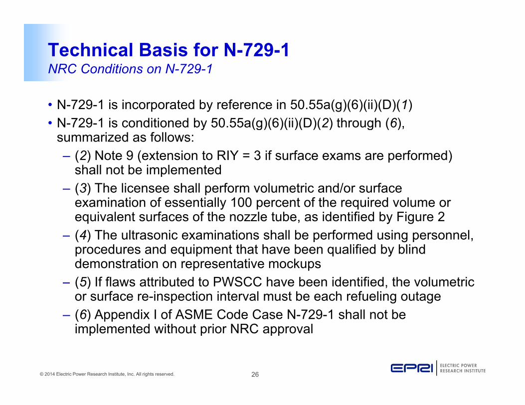
Technical Basis for N-729-1NRC Conditions on N-729-1
• N-729-1 is incorporated by reference in 50.55a(g)(6)(ii)(D)(1)• N-729-1 is conditioned by 50 55a(g)(6)(ii)(D)(2) through (6)N 729 1 is conditioned by 50.55a(g)(6)(ii)(D)(2) through (6),
summarized as follows:– (2) Note 9 (extension to RIY = 3 if surface exams are performed)
shall not be implemented– (3) The licensee shall perform volumetric and/or surface
examination of essentially 100 percent of the required volume or equivalent surfaces of the nozzle tube, as identified by Figure 2
– (4) The ultrasonic examinations shall be performed using personnel, procedures and equipment that have been qualified by blind demonstration on representative mockups(5) If fl tt ib t d t PWSCC h b id tifi d th l t i– (5) If flaws attributed to PWSCC have been identified, the volumetric or surface re-inspection interval must be each refueling outage
– (6) Appendix I of ASME Code Case N-729-1 shall not be implemented without prior NRC approval
© 2014 Electric Power Research Institute, Inc. All rights reserved. 26
implemented without prior NRC approval

Updated Technical Basis (MRP-395)
© 2014 Electric Power Research Institute, Inc. All rights reserved. 27

IntroductionScope of MRP-395p
• All Alloy 600 top head J-groove nozzles in U.S. PWRs
– Same scope as for ASME Code Case N-729-1
© 2014 Electric Power Research Institute, Inc. All rights reserved. 28

IntroductionRelevant Documents
Crack Growth Rates for Evaluating Primary Water Stress Corrosion
Cracking (PWSCC) of Thick-Wall Alloy 600 Materials
(MRP-55) Revision 1
Crack Growth Rates for Evaluating Primary Water Stress Corrosion Cracking (PWSCC) of Alloy 82,
182, and 132 Welds (MRP-115)
Interim Alloy 600 Safety Assessments for US PWR Plants: Part 2: Reactor Vessel Top Head
Penetrations(MRP-44)
Response to NRC Bulletin 2001-01 (MRP-48)
[Tables of Head-Specific Info]
Reactor Vessel Head Nozzle and Weld Safety Assessment for B&W
Plants(MRP-103)
RV Head Nozzle and Weld Safety Assessment for Westinghouse and Combustion Engineering Plants
(MRP-104)
Probabilistic Fracture Mechanics Analysis of PWR Reactor Pressure Vessel Top Head Nozzle Cracking
(MRP-105)
Demonstrations of Vendor Equipment and Procedures for the Inspection of Control Rod Drive Mechanism Head Penetrations
(MRP 89)(MRP 103) (MRP 104) (MRP 105) (MRP-89)
Reactor Vessel Closure Head Penetration Safety Assessment for
U S PWR Pl t E l ti
Generic Evaluation of Examination Coverage Requirements for Reactor
Visual Examination for Leakage of PWR Reactor Head Penetrations: Revision 2 of 1006296 [MRP-60],
ASME BPVC Section XIIWB-3660
U.S. PWR Plants: Evaluations Supporting the MRP Inspection Plan
(MRP-110)[Top Level Safety Assessment]
g q fPressure Vessel Head Penetration
Nozzles(MRP-95R1) Revision 1
f [ ]Includes 2002 Inspection Results and
MRP Inspection Guidance(EPRI 1007842)
[3002000711 is Rev. 3]
ASME BPVC Section XINon-Mandatory Appendix O
Inspection Plan for Reactor Vessel Closure Head Penetrations in U.S.
PWR Plants(MRP-117)
[Technical Basis Summary]
Reevaluation of Technical Basis for Inspection of Alloy 600 PWR
Reactor Vessel Top Head Nozzles (MRP-395)
ASME Code Case N-729-1
ASME Code Case N-729-4
© 2014 Electric Power Research Institute, Inc. All rights reserved. 29
[Technical Basis Summary]
Tcold RV Closure Head Nozzle Inspection Impact Assessment
(MRP Letter 2011-034)

Updated Technical Basis (MRP-395):Assessment of Plant ExperienceAssessment of Plant Experience
© 2014 Electric Power Research Institute, Inc. All rights reserved. 30
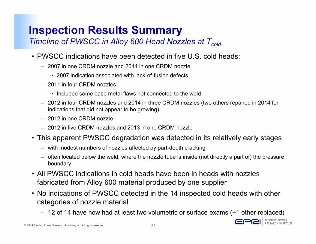
Inspection Results SummaryTimeline of PWSCC in Alloy 600 Head Nozzles at Tcoldy cold
• PWSCC indications have been detected in five U.S. cold heads:– 2007 in one CRDM nozzle and 2014 in one CRDM nozzle
• 2007 indication associated with lack-of-fusion defects• 2007 indication associated with lack-of-fusion defects– 2011 in four CRDM nozzles
• Included some base metal flaws not connected to the weld– 2012 in four CRDM nozzles and 2014 in three CRDM nozzles (two others repaired in 2014 for
indications that did not appear to be growing)– 2012 in one CRDM nozzle– 2012 in five CRDM nozzles and 2013 in one CRDM nozzle
• This apparent PWSCC degradation was detected in its relatively early stages• This apparent PWSCC degradation was detected in its relatively early stages– with modest numbers of nozzles affected by part-depth cracking– often located below the weld, where the nozzle tube is inside (not directly a part of) the pressure
boundary
• All PWSCC indications in cold heads have been in heads with nozzles fabricated from Alloy 600 material produced by one supplier
• No indications of PWSCC detected in the 14 inspected cold heads with other
© 2014 Electric Power Research Institute, Inc. All rights reserved. 31
categories of nozzle material– 12 of 14 have now had at least two volumetric or surface exams (+1 other replaced)

Updated Assessment of Plant ExperienceEffect of Time at Temperature – NDE Results for 24 Heads with Alloy 600 Nozzles Still in Service600 Nozzles Still in Service
30
25
ND
E
NDE with Cracks ReportedNDE without Cracks Reported
15
20
of M
ost R
ecen
t N
10
ED
Ys a
t Tim
e o
0
5
© 2014 Electric Power Research Institute, Inc. All rights reserved. 32
0540 550 560 570 580 590 600 610 620
Head Temperature (°F) per MRP-48*
* Head temperatures for B&W designed plants assumed to be 8°F higher than Thot

Updated Assessment of Plant ExperienceU.S. Fleet Status – PWSCC Detections in Top Head Nozzlesp
70
80
CRDM/CEDM Nozzles with NewlyDetected Cracks by NDE
50
60
Noz
zles
y
CRDM/CEDM Nozzles with NewlyDetected Leaks by Direct Visual
40
50
CR
DM
/CE
DM
2010 Cracks/Leaks are for1st NDE Examination of a
l All 600 d
NRC Order EA-03-009February 11, 2003
20
30
Num
ber
of Replacement Alloy 600 Head
Implementation of ASMECode Case N–729–1
0
10
© 2014 Electric Power Research Institute, Inc. All rights reserved. 33
<2000 2000 2001 2002 2003 2004 2005 2006 2007 2008 2009 2010 2011 2012 2013 2014Year

Updated Assessment of Plant ExperienceEffect of Time at Temperature – NDE Results for 63 Heads with Alloy 600 Nozzles600 Nozzles
45
35
40
zzle
s
NDE with Cracks ReportedDirect Visual with Leaks ReportedNDE without Cracks Reported
25
30
RD
M/C
ED
M N
oz
15
20
Num
ber
of C
R
0
5
10
© 2014 Electric Power Research Institute, Inc. All rights reserved. 34
00 5 10 15 20 25 30 35
EDYs at Time of Most Recent Inspection

Effectiveness of Current Inspection RequirementsRequirements
• The current requirements have been effective in detecting the PWSCC reported in a timely fashion, well before the degradation SCC epo ted a t e y as o , e be o e t e deg adat oproduces flaws of direct safety significance– No nozzle leaks have been detected via visuals after the
outage of the first in-service volumetric/surface exam of alloutage of the first in service volumetric/surface exam of all CRDM/CEDM nozzles
– Since 2004, no circumferential PWSCC indications located near or above the top of the weld have been detectednear or above the top of the weld have been detected
– The only occurrence of nozzle leakage since 2004 was detected in 2010 during the first in-service volumetric NDE inspection performed of a replacement Alloy 600 head from ainspection performed of a replacement Alloy 600 head from a cancelled plant
– The cold head exams and the repeat exams performed on non-cold heads have been effective in detecting the PWSCC
© 2014 Electric Power Research Institute, Inc. All rights reserved. 35
non cold heads have been effective in detecting the PWSCC reported in its early stages

Sufficiency of Current Requirements for Visual Exams of Cold Heads (1/3)( )
• Experience has shown that PWSCC flaws located in the weld metal often extend into the base metal, and are thus detectable via UT fromoften extend into the base metal, and are thus detectable via UT from the nozzle ID
• Most of the industry experience with PWSCC flaws has been those that initiated on the OD of the tube material, primarily at the interface withinitiated on the OD of the tube material, primarily at the interface with the J-groove-weld– These areas can be effectively examined ultrasonically
• There have been no cases of weld flaws growing to the annulus and• There have been no cases of weld flaws growing to the annulus and causing leakage after a UT examination has been performed of 100% of the CRDM/CEDM nozzles in a head
Most susceptible heads operating at the highest temperatures have– Most susceptible heads operating at the highest temperatures have been replaced
– Nonetheless there have been no cases of detected leakage after UT has been first applied to all CRDM/CEDM no les in a head
© 2014 Electric Power Research Institute, Inc. All rights reserved. 36
has been first applied to all CRDM/CEDM nozzles in a head

Sufficiency of Current Requirements for Visual Exams of Cold Heads (2/3)( )
• There is no direct safety significance of flaws located exclusively in the weld metal:– J-groove welds are large welds with significant structural margin. Nozzle
ejection due to a flaw located exclusively in the J-groove-weld is not credible– The leak rate produced by a flaw exclusively located in the weld metal is y y
likely to be much smaller than that which could result in significant boric acid corrosion of the low-alloy steel material
• For a weld flaw to lead to the possibility of af t i ifi t i f ti l fl i thsafety-significant circumferential flaw in the
nozzle tube (i.e., a large circumferential flawlocated in the nozzle tube that could lead tonozzle ejection if it were to grow to encompass
Typical growth of weld-initiated flaws
j g pa large fraction of the wall cross section) wouldvery likely require that leakage be produced thatis detectable during visual examinations of theupper head surface
© 2014 Electric Power Research Institute, Inc. All rights reserved. 37
upper head surface

Sufficiency of Current Requirements for Visual Exams of Cold Heads (3/3)( )• Evidence of leakage detectable by visual
examination was present in all 7 cases of circumferential cracking in the CRDMcircumferential cracking in the CRDM nozzle tube above the top of the weld (all predating N-729; see Section 4 of MRP-110)Th d t il d b bili ti l l ti f• The detailed probabilistic calculations of MRP-395 explicitly model the possibility of a pre-existing weld flaw ultimately leading to nozzle ejection
• The modeling work demonstrates an acceptably small effect on nuclear safety – The probabilistic modeling maintains the
key conservatism of the originalkey conservatism of the original MRP-105 probabilistic technical basis that a weld flaw reaching the nozzle annulus is assumed to immediately produce a 30° through wall
© 2014 Electric Power Research Institute, Inc. All rights reserved. 38
produce a 30 through-wall circumferential flaw in the nozzle tube

Industry Weibull FitTime to First PWSCC Initiation on Alloy 600 Top Headsy p
• Based on two-parameter Weibull model fit to plant detection data– Multiple indications on a top head are resolved by back-extrapolating
time of first initiation assuming a Weibull slope of 3g p
0.90
All inspection data adjusted to 600 °F (Q = 50 kcal/mole)
Median Rank Regression yields Weibull characteristictime θ = 15 21 EDYs
Weibull model fit to U.S. plant data in 2003 for top head detections
Plant E
Plant AD0.90
All inspection data adjusted to 600 °F (Q = 50 kcal/mole)
Median Rank Regression yieldsWeibull characteristic timeθ = 23.2 EDYs
Weibull model fit to U.S. plant data in 2011 for top head detections
Plant BJPlant P
Plant BLPlant BH
Plant O
Plant E
Plant AL
0.50
0.63
age/
Cra
ckin
g
time θ = 15.21 EDYs
Plant P
Plant AQ
Plant O
Plant AL
Plant AR
Plant BL
Plant BQ
Plant BJ
Pl t BQPlant BJPlant BL
Plant BKPlant E
Plant O
Plant AL
0.50
0.63
h C
rack
ing
Plant K
Plant AR
Plant BQ
Plant ABPlant BJ
Plant AD0.10
0.20
Frac
tion
of U
nits
with
Lea
ka
Weibull slope ofb = 3 assumed for fitto extrapolated data Plant H
Plant BO
Plant AB
Plant Q
Plant K
Plant BKPlant BH
Plant P
Plant BO
Plant K
Plant BHPlant HPlant PPlant AR
Plant ADPlant AB
Plant QPlant BQ
0.10
0.20
ulat
ive
Frac
tion
of U
nits
with
Actual Weibull slope (1.60) used for fitto extrapolated data
Plant AQ
Plant BO
0.02
0.05
Cum
ulat
ive
EDYs at detection of leakage or cracking
to extrapolated data
Plant AK
Plant V
Plant H
Plant N
Plant V
Plant AQ
0.02
0.05
Cum
u
EDYs at detection of leakage or cracking
EDYs at first leak or crack extrapolatedback using slope b = 3
© 2014 Electric Power Research Institute, Inc. All rights reserved. 39
0.011 10 100
EDYs
EDYs at first leak or crack extrapolatedback using slope b = 3
Plant NPlant AK
0.011 10 100
EDYs
Mean theta - 1.65 standard deviations (18.7)
Mean theta + 1.65 standard deviations (28.9)

Industry Weibull FitUpdated to Latest Alloy 600 Top Head PWSCC ExperiencePWSCC Experience
0.90
All inspection data adjusted to 600 °F (Q = 50 kcal/mole)
Median Rank Regression yieldsWeibull characteristic timeθ = 23 0 EDYs
• Considers additional PWSCC reported at three cold heads up to
0.50
0.63
Cra
ckin
g
θ = 23.0 EDYsreported at three cold heads up to 2013:– 6 nozzles at one cold head (5 in
2012, 1 in 2013)4 nozzles at one cold head
0.20
e Fr
actio
n of
Uni
ts w
ith
Actual Weibull slope (1.38) used for fitto extrapolated data
– 4 nozzles at one cold head (2012)
– 1 nozzle at one cold head (2012)– 2014 experience subsequent to
0.05
0.10
Cum
ulat
ivep q
MRP-395 calcs was for additional nozzles in already affected heads
• Similar to fit in 2011
0.01
0.02
1 10 100
EDYs at detection of cracking
EDYs at first crack extrapolated back usingslope b = 3Mean theta - 1.65 standard deviations (16.6)
Mean theta + 1.65 standard deviations (31.8)
– Slightly reduced Weibull slope (1.38 vs. 1.60)
– Slight increase in probability of cracking for small EDY values
© 2014 Electric Power Research Institute, Inc. All rights reserved. 40
1 10 100
EDYscracking for small EDY values (applicable to cold heads)

Industry Weibull FitTop Head Alloy 600 PWSCC Experience for B&WTP MaterialExperience for B&WTP Material
0.90
All inspection data adjusted to 600 °F (Q = 50 kcal/mole)
Median Rank Regression yieldsWeibull characteristic timeθ = 11.0 EDYs
• Considers cracking experience at 16 top heads
0.50
0.63
h C
rack
ing
Actual Weibull slope (1.17) used for fitto extrapolated data
experience at 16 top heads with B&WTP material, reported up to 2013– 6 of these top heads still
0.10
0.20
ve F
ract
ion
of U
nits
with
poperating (all at Tcold)
• More aggressive than fit to all material suppliers
0.05
0.10
Cum
ulat
ivEDYs at detection of cracking
– Reduced time it takes to have half of heads affected (from 18 to 8 EDY) Reflects an increase in
0.01
0.02
1 10 100
EDYs at detection of cracking
EDYs at first crack extrapolated back usingslope b = 3Mean theta - 1.65 standard deviations (6.6)
Mean theta + 1.65 standard deviations (18.4)
– Reflects an increase in probability of cracking, particularly at small EDY values (applicable to cold
© 2014 Electric Power Research Institute, Inc. All rights reserved. 41
EDYsheads)

Updated Assessment of Plant ExperienceImplied Crack Growth Rates – Cold Headsp
• Flaw indication data from the following experience were assessed for their consistency with the crack growth rate assumptions of thetheir consistency with the crack growth rate assumptions of the probabilistic analyses:
– 2011 Cold Head Experience– 1st 2012 Cold Head Experiencep– 2nd 2012 Cold Head Experience– 2013 Cold Head Experience– 2014 Cold Head Experience– 1994-96 Non-Cold Head Experience– 2005 Non-Cold Head Experience– 2009 Non-Cold Head Experience
2010 Non Cold Head Experience– 2010 Non-Cold Head Experience
• The results are consistent with the crack growth rate assumptions of the probabilistic analyses, with crack growth rate material variability percentiles less than 95%
© 2014 Electric Power Research Institute, Inc. All rights reserved. 42
percentiles less than 95%

Updated Assessment of Plant ExperienceConclusions
• Lower incidence and extent of PWSCC in nozzles on cold heads is consistent with the large sensitivity to operating temperatureconsistent with the large sensitivity to operating temperature
• Inspection experience for other locations operating at Tcold including BMNs corroborates a low frequency of PWSCC in Alloy 600 top head nozzles operating at Tcoldnozzles operating at Tcold
• Fitting a Weibull model specific to experience with B&W Tubular Products material results in a more aggressive initiation model
• Plant experience including the recent experience with part depth• Plant experience including the recent experience with part-depth PWSCC in a limited number of CRDM nozzles operating at Tcoldvalidates the conclusions of the original N-729-1 technical basis
© 2014 Electric Power Research Institute, Inc. All rights reserved. 43

Updated Assessment of Plant ExperienceConclusions (cont’d)( )
• The experience for colds heads with PWSCC shows that a two cycle l t i f i t l ld till h d t t dvolumetric or surface exam interval would still have detected
indications in the early stages of nozzle degradation, including with substantial margins against leakage
– One nozzle with a PWSCC indication in 2014 was detected at a Tcold plant volumetrically inspecting every other outage
• Indication was about 35% through-wall at time of repairIndication was about 35% through wall at time of repair
• Indication was axial, at the weld toe, and almost an inch below the nozzle annulus
• Demonstrates the effectiveness of such an inspection frequency
© 2014 Electric Power Research Institute, Inc. All rights reserved. 44

Updated Technical Basis (MRP-395):Deterministic AnalysesDeterministic Analyses
© 2014 Electric Power Research Institute, Inc. All rights reserved. 45

Deterministic ModelingApproachpp
• Crack growth calculations modeled using 75th percentile growth models from MRP-55R1 and MRP-115growth models from MRP 55R1 and MRP 115
• Part-depth flaws modeled to start at 10% thickness (assumed detectable flaw size) and growth through-wallTh h ll i f ti l fl t th J ld• Through-wall circumferential flaws at the J-groove weld modeled to start at 30° and grow to 300°
• Results of various existing growth calculations were g gadjusted to 555°F, 563°F, and 605°F– MRP-105
Examination frequency relief request– Examination frequency relief request– Technical basis for CRDM nozzle inspection interval– Calculations performed for this report
© 2014 Electric Power Research Institute, Inc. All rights reserved. 46
p p

Deterministic ModelingResults
• Time between assumed detectable flaw size (10% TW) and leakage (100% TW) for cases considered:leakage (100% TW) for cases considered:– Between RIY = 2.6 and RIY = 5.3– Equivalent to between 8.4 and 17 EFPY at 555°F,Equivalent to between 8.4 and 17 EFPY at 555 F,
between 6.7 and 14 EFPY at 563°F, and 2.3 and 4.7 EFPY at 605°F
( °• Time between evident leakage (assumed through-wall 30°circumferential flaw) and risk of net section collapse (assumed to result at 300°) for cases considered:( )– Between RIY = 8.3 and 22– Equivalent to between 27 and 72 EFPY at 555°F, 22 and
© 2014 Electric Power Research Institute, Inc. All rights reserved. 47
58 EFPY at 563°F, and 7.4 and 20 EFPY at 605°F

Deterministic ModelingConclusions
• Results for part-depth flaws provide confidence that inspection intervals are sufficient to prevent leakageinspection intervals are sufficient to prevent leakage
• Results for circumferential flaws demonstrate large margins to preclude possibility of nozzle ejectionp p y j
© 2014 Electric Power Research Institute, Inc. All rights reserved. 48

Updated Technical Basis (MRP-395):Probabilistic AnalysesProbabilistic Analyses
© 2014 Electric Power Research Institute, Inc. All rights reserved. 49

Probabilistic ModelingApproachpp
• Probabilistic model is essentially the same as that presented in the appendices of MRP-375 (EPRI 3002002441) and Appendix B of MRP-335appendices of MRP 375 (EPRI 3002002441) and Appendix B of MRP 335 Rev. 1 (EPRI 3002000073)– Additional flexibility added to scheduling of first simulated inspection
• Initiation model parameter inputs are based on updated Weibull fits– Weibull fit to all material suppliers– Weibull fit to nozzle material supplied by B&WTP
Bounding Weibull case calibrated to “Alloy 600 replacement head”– Bounding Weibull case calibrated to Alloy 600 replacement head” experience
• Models “cold” heads as well as “hot” heads operating near the hot-leg temperature (605°F was assumed)p ( )
• Investigate dependence of probabilistic results to various sensitivity cases– Inspection sensitivity cases
M d l iti it
© 2014 Electric Power Research Institute, Inc. All rights reserved. 50
– Model sensitivity cases

Probabilistic ApproachDescription of RPVHPN Probabilistic Modelp
0.2
0.4
0.6
0.8
Samplecomponent-specific
random variables
Load/Stress Module
Loop
Calculate SIFsSample penetration-
specific variablesne
tratio
n Lo
op
0.2
0.4
0.6
0.8
Samplecomponent-specific
random variables
Sample head-specific random
variables
• Monte Carlo (MC) i l ti t
00 1 2 3 4 5
Initiation Cycle
Loo
p
-Cyc
le Lo
op Activ
e Flaw
L
Growth Module
Pen0
0 1 2 3 4 5
simulation propagates uncertainty through the constituent models to estimate failure risk
1 .4 E - 0 3
9 %
1 0 %
f
Cumulative Probability of LeakageIncremental Probability of Leakage
Store Failures Counters for Statistics Generated at the End of All Monte Carlo Realizations
0.4
0.6
0.8
Sampleflaw-specific
random variables
Module
C
Sub-
Crack Interaction and Transition Rules
Sample flaw-specific variables
to estimate failure risk
• Diagram describes a general MC realization within the framework
2 .0 E - 0 4
4 .0 E - 0 4
6 .0 E - 0 4
8 .0 E - 0 4
1 .0 E - 0 3
1 .2 E - 0 3
1 %
2 %
3 %
4 %
5 %
6 %
7 %
8 %
Incr
emen
tal P
roba
bilit
y of
Leak
age
Cum
ulat
ive
Prob
abili
ty o
f Le
akag
e
Incremental Probability of Leakage
0
0.2
0 1 2 3 4 5
Initiation(s)
Failure Occurred
During Sub-Cycle?
yes
yeswithin the framework
• Modeling highlights are presented in next slides
0 .0 E + 0 00 %
0 10 20 30 40 50 60 70EFPY
0 30.40.50.60.70.80.9
1
roba
bilit
y of D
etec
tion
Before End of Life?
Crac
k Loo
p
All Cycles Complete without
yes
© 2014 Electric Power Research Institute, Inc. All rights reserved. 51
slides0
0.10.20.3
0.0 0.2 0.4 0.6 0.8 1.0 1.2 1.4 1.6 1.8
Pr
Depth (mm)
Examination and Repair Modules
C without Failure?

Probabilistic ApproachComponent Modelingp g
• Alloy 600 Reactor Pressure Vessel Head Penetration Nozzles (RPVHPNs)– Multiple penetration nozzles per top head– Flaws can initiate on ID, OD below weld, and J-groove weld wetted
surfaces on uphill or downhill side• Initiation time is sampled from a multiple flaw initiation Weibull model
for these six locations
Alloy 600 Nozzle
for these six locations • Operational loads are superimposed with residual stresses to calculate the stress intensity factor and growth rate
• Growth of circumferential flaws in the nozzle tube along th ld t d l d i 3D FEA h
U hill
Alloy 182 Weld
Alloy 182 Buttering
Low Alloy Steel Head
the weld contour modeled using a 3D FEA approach• Leakage criterion is satisfied if a flaw breeches the OD nozzle annulus
– Assumed to immediately initiate
ID FlawDownhill
UphillOD Flaw
Weld Flaw
Stainless Steel Clad
Assumed to immediately initiate a 30° circumferential flaw
• Ejection criterion is satisfied if circumferential through-wall cracking along the J-groove weld contour reaches critical size (~300-330°)
© 2014 Electric Power Research Institute, Inc. All rights reserved. 52
weld contour reaches critical size ( 300 330 )

Probabilistic ApproachNon-Destructive Examination (NDE)—Correlation of Successive Exams( )
• Probability of flaw detection (POD) models were developed using lifi i d d d d d d l iqualification data, vendor data, standards, and plant experience
• NDE methods included in simulations:– Ultrasonic testing (UT) for
0.8
0.9
1
n
Example POD evolution with initial POD of 90%
(based on numerical study)
Ultrasonic testing (UT) for flaws in base metal
– Eddy current testing (ET) forfla s on etted s rfaces
0.4
0.5
0.6
0.7
abilit
y of D
etec
tion
Modest Correlation
(based on numerical study)flaws on wetted surfaces– Visual examination (VE)
exam for evidence of leakage
0
0.1
0.2
0.3Prob
a
Strong Correlation• Correlated sampling for successive examinations simulates effect of flaw
© 2014 Electric Power Research Institute, Inc. All rights reserved. 53
00 1 2 3 4 5 6
Number of Succesive Non-Detections
simulates effect of flawcharacteristics on POD

Probabilistic ApproachCases Evaluated
• Three temperatures studied with inspection intervals of RIY = 2.25:– 1 (24-month) cycle at 605°F1 (24 month) cycle at 605 F– 4 (18-month) cycles at 563°F– 5 (18-month) cycles at 555°F
• Three inspection intervals studied:O f li l– One refueling cycle
– Two refueling cycles– 2.25 RIY
• Three initiation Weibull models studied:– All material supplier Weibull– B&W Tubular Products Weibull– Weibull calibrated to the results of the “Alloy 600 replacement head” inspection
• Various sensitivity cases performed to verify robustness of conclusions to modeling and• Various sensitivity cases performed to verify robustness of conclusions to modeling and input assumptions
• Model benchmarked versus MRP-105 as a software validation and verification activity; resulted in reasonable agreement considering detailed differences in modeling methodology
© 2014 Electric Power Research Institute, Inc. All rights reserved. 54
g gy

Weibull Initiation ModelCalibration to Replacement Alloy 600 Head
0.90
1.00
Median prediction consistent with 12
l ith UT
p y
• Compile detection data from first inspection of an Alloy 600 replacement head, operating from 2004 to 2010
0.60
0.70
0.80
ency
nozzles with UT detections
from 2004 to 2010– 12 nozzle with UT detections, 9 nozzles
with ET detections on weld, and an additional 3 nozzle detections by PT on weld
0 30
0.40
0.50
Cum
ulat
ive F
requ
e
• Simulate conditions of the Alloy 600 replacement head and calibrate initiation Weibull model parameters to obtain median of 12 UT detections in base metal
Median prediction consistent with 12 additional detections
on weld
0.10
0.20
0.30C
B&W Material Slope, UT onlyB&W Material Slope, UT & ETWeibull Slope of 3, UT onlyWeibull Slope of 3, UT & ET
– Apply best-estimate temperature and actual number of nozzles
– Simulate UT and ET examination after 6 years of simulated operation
0.000 10 20 30 40 50 60 70 80
Number of Nozzle Repairs per Head
– Apply uncertainty in Weibull initiation model derived from data for B&WTP material
• Use calibrated initiation parameters in main probabilistic assessment cases to ensure that
Initiation model calibrated for two Weibull slopes• Standard slope assumption (b = 3)
© 2014 Electric Power Research Institute, Inc. All rights reserved. 55
probabilistic assessment cases to ensure that results cover all operating heads
Standard slope assumption (b 3)• Best-fit Weibull slope to B&WTP data (b = 1.17)

Weibull Initiation ModelModels Used in MRP-395 All inspection data adjusted to 600 °F (Q = 50 kcal/mole)
• Comparison of three crack 0.63
0.90
initiation Weibull models used in study
0.50
Cra
ckin
g
1st Replacement Alloy 600 Calibration Weibull
0 10
0.20
actio
n of
Uni
ts w
ith
Fit to B&W TP material data
0.05
0.10
Cum
ulat
ive
Fra
Fit to all material supplier data
0.02
© 2014 Electric Power Research Institute, Inc. All rights reserved. 56
0.011 10 100
EDYs

Probabilistic Results FormatReported Statistics and Target Criteriap g
• Average Ejection Frequency (AEF) – average rate (per ) f j ti h dyear) of ejections per head
• Average Leakage Frequency (ALF) – average rate (per year) of new leaking penetrations per headyear) of new leaking penetrations per head
• Nozzle Ejection Frequency Criterion (per Head Basis)– Maximum acceptable time-averaged core damage– Maximum acceptable time-averaged core damage
frequency = 1E-6 / yr– Upper bound conditional core damage probability for
medium-break LOCA = 2E-2 – Acceptance criterion for the nozzle ejection frequency is
1E-6 / 2E-2 = 5E-5 / yr
© 2014 Electric Power Research Institute, Inc. All rights reserved. 57
1E-6 / 2E-2 = 5E-5 / yr

Main ResultsAverage Ejection Frequency Versus Temperature, UT Inspection Period, and Assumed Initiation Model
1.E-2B&W TPW ib ll
1st D-B Replacement
All MaterialSuppliers
and Assumed Initiation Model
1 E 4
1.E-3
y (pe
r Yea
r) on
Weibull Replacement Head Weibull
Suppliers Weibull
Increase in temperature increases ejection frequency modestly
Most unfavorable conditions predicted to
remain below 5E-05
Heads more susceptible to PWSCC initiation demonstrate
3.7E-6
1.6E-5
5.3E-6
2 3E 6
2.1E-5
1.E-5
1.E-4
on F
requ
ency
Firs
t Ins
pect
io initiation demonstrate larger ejection rates
8 9E 8
1.0E-6
2.2E-71.6E-7
7.9E-7
2.4E-7
1.8E-6
1.6E-7
7.0E-74.1E-7
2.3E-6
1.E-6
vera
ge E
jectio
Afte
r F
4.0E-8
8.9E-85.7E-8 7.1E-8
1.E-8
1.E-7
1 2 5 1 2 5 1 2 5 1 2 4 1 2 4 1 2 4
Av
© 2014 Electric Power Research Institute, Inc. All rights reserved. 58
1 2 5 1 2 5 1 2 5 1 2 4 1 2 4 1 2 4UT Inspection Period (18-month cycles)
555°F Cases 563°F Cases

Main ResultsAverage Leakage Frequency Versus Temperature, UT Inspection Period, and Assumed Initiation Model
0.60B&W TP 1st D-B
ReplacementAll MaterialSuppliers
and Assumed Initiation Model
3 9E 1
0.50
(per
Yea
r) n
Weibull Replacement Head Weibull
Suppliers Weibull Heads more susceptible to
PWSCC initiation demonstrate drastically larger leakage rates
2.7E-1
3.4E-1
2.8E-1
3.3E-1
3.9E-1
0.30
0.40
e Fre
quen
cy
rst I
nspe
ctio
n
2.3E-1
0.20
erag
e Lea
kage
Afte
r Fi Nominal cold heads
predicted to remain below 0.05 instances of new leakage per year for all
inspection intervals
Average leakage rate only modestly improved by more
frequent inspection (sub-linear trend)
1.6E-2 1.7E-2 2.0E-25.0E-2 5.5E-2 6.6E-2
2.4E-2 2.6E-2 2.9E-2
7.0E-2 7.7E-2 8.8E-2
0.00
0.10
1 2 5 1 2 5 1 2 5 1 2 4 1 2 4 1 2 4
Ave
© 2014 Electric Power Research Institute, Inc. All rights reserved. 59
1 2 5 1 2 5 1 2 5 1 2 4 1 2 4 1 2 4UT Inspection Period (18-month cycles)
555°F Cases 563°F Cases
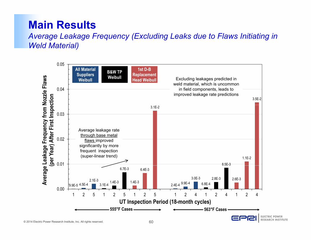
Main ResultsAverage Leakage Frequency (Excluding Leaks due to Flaws Initiating in Weld Material)
0.05B&W TP 1st D-B
ReplacementAll MaterialSuppliers
Weld Material)
3.5E-2
0.04
Nozz
le Fl
aws
ctio
n
Weibull Replacement Head Weibull
Suppliers Weibull Excluding leakages predicted in
weld material, which is uncommon in field components, leads to
improved leakage rate predictions
3.1E-2
0.03
quen
cy fr
om N
er F
irst I
nspe
c
Average leakage rate through base metal
8.5E-31.1E-2
0.01
0.02
Leak
age F
req
(per
Yea
r) Af
te through base metal flaws improved
significantly by more frequent inspection (super-linear trend)
9.9E-5 4.5E-42.1E-3
3.1E-41.4E-3
6.7E-3
1.4E-3
6.4E-3
2.4E-4 9.9E-43.0E-3
6.8E-42.8E-3
8.5E 3
2.6E-3
0.00
0.01
1 2 5 1 2 5 1 2 5 1 2 4 1 2 4 1 2 4
Aver
age (
© 2014 Electric Power Research Institute, Inc. All rights reserved. 60
1 2 5 1 2 5 1 2 5 1 2 4 1 2 4 1 2 4UT Inspection Period (18-month cycles)
555°F Cases 563°F Cases

Main ResultsIncremental Ejection Frequency Versus Time for Different Temperature Heads Under N 729 1 Inspection RequirementsHeads Under N-729-1 Inspection Requirements
Hot head uninspected for over 20 EFPYs predicted to have 10% likelihood of ejection per year. This demonstrates model conservatism. Predictions after first inspection are relevant to the benefit of periodic exams.
1.0E-1
1.0E+0
per Y
ear 563°F, 4 cycle UT, D-B Replacement Weibull
555°F, 5 cycle UT, D-B Replacement Weibull605°F, 1 cyc. UT, All Material Supplier Weibull
1 0E 4
1.0E-3
1.0E-2
cy o
f Ejec
tion
Peaks correspond with cyclepreceding first UT inspection Implementation of N-729-1
inspection intervals predicted to stabilize ejection risk
1.0E-6
1.0E-5
1.0E-4
enta
l Fre
quen
c
1.0E-8
1.0E-7
1.0E 6
0 10 20 30 40 50 60
Incr
eme
© 2014 Electric Power Research Institute, Inc. All rights reserved. 61
0 10 20 30 40 50 60
EFPY

Sensitivity CasesEffect of Initiation-Growth Correlation on Growth Rate of Active Flaws
• Negative correlation 1 0
coefficient between initiation and growth simulates that a material more susceptible to PWSCC i iti ti i
0.8
0.9
1.0
yPWSCC initiation is more susceptible to PWSCC growth
0.5
0.6
0.7
ulat
ive F
requ
ency
Correlation
Correlation Coefficient of -0.8
• Evaluated effect of correlation on growth rate by recording growth factor for i iti t d fl d i M t
0.2
0.3
0.4Cum
u
Correlation Coefficient of +0 8
Correlation Coefficient of 0.0
Coefficient of -0.5
initiated flaws during Monte Carlo experiment
0.0
0.1
0 1 2 3 4 5 6 7
Factor on Growth of Alloy 182 Material
Coefficient of +0.8
© 2014 Electric Power Research Institute, Inc. All rights reserved. 62
Factor on Growth of Alloy 182 Material

Discussion of Results
• Even for cold head modeled to have material as susceptible as the “Alloy 600 replacement” head risk of ejection is acceptablythe Alloy 600 replacement head, risk of ejection is acceptably low for inspections scheduled per RIY = 2.25
• Leakage probabilities are influenced by the rate of initiated flaws
• Inspections are effective in maintaining a low probability of leakage due to base metal cracking
– The leakage results excluding flaws initiated in the base metal are most realistic as plant experience shows a low probability of leakage due to flaws located exclusively in the weld metal
• The “Alloy 600 replacement head” Weibull model is conservative since it bounds plant experience
© 2014 Electric Power Research Institute, Inc. All rights reserved. 63

Probabilistic Modeling Conservatisms
• Significant modeling conservatisms are maintained in the current probabilistic approach supporting the aforementioned conclusions:probabilistic approach supporting the aforementioned conclusions:
– PWSCC initiation is assumed uniform at ID, OD and weld locations and weld flaws are modeled as being undetectable prior to leakage
– A through-wall 30° circumferential flaw located at the top of the weld is assumed to be produced immediately upon nozzle leakage
– Conservatively low POD values for UT and VE were assumedy
– An environmental factor was assumed to increase the growth rate of circumferential cracks in contact with the OD annulus of RPVHPNs
– Axial ID flaws on RPVHPN tubes are assumed to always initiate at the elevation having the highest hoop stresses
Bounding high K solutions are used in some cases for flaw growth
© 2014 Electric Power Research Institute, Inc. All rights reserved. 64
– Bounding high K solutions are used in some cases for flaw growth

Updated Technical Basis (MRP-395):Assessment of Concern for Boric Acid
Corrosion (BAC)
© 2014 Electric Power Research Institute, Inc. All rights reserved. 65

BAC Wastage EvaluationsIntroduction
• The periodic visual examinations for evidence of pressure boundary leakage of ASME Code Case N-729-1 conservatively addresses the g yconcern for boric acid corrosion– Original technical basis was summarized in Section 3.4 of MRP-117
• Bare metal visual examination (VE) interval of lesser of every third refueling outage or 5 years for heads with < 8 EDY (effectively those at Tcold) and no previously detected PWSCC– Very low probability of leakage calculated for such heads in
MRP 105MRP-105– Slower crack growth means longer time for the leak rate to in
increase to a point that may support boric acid wastage (Section 7 of MRP-110)MRP-110)
– Visual assessment including under the insulation from multiple access points (VT-2) is required during the other refueling outages to check for gross evidence of the buildup of boron and/or corrosion
© 2014 Electric Power Research Institute, Inc. All rights reserved. 66
g pproduct deposits

BAC Wastage EvaluationsPlant Experiencep
• No through-wall cracking has been observed in the U.S. after the first in-service volumetric or surface examinationafter the first in service volumetric or surface examination was performed of all CRDM or CEDM nozzles in a given head
• Periodic visual examinations performed under the• Periodic visual examinations performed under the insulation at appropriate intervals are highly effective in detecting any leakage caused by PWSCC before any discernible material lossdiscernible material loss – 2010 case of multiple leaking CRDM nozzles resulted in
no discernable corrosion of the low-alloy steel head– Periodic BMV detected 2013 case of reactor vessel
bottom-mounted nozzle leakage at a U.S. PWR before wastage occurred
© 2014 Electric Power Research Institute, Inc. All rights reserved. 67
g

BAC Wastage EvaluationsExperience with Leaking CRDM Nozzlesp g
• Most leaking CRDM nozzles were repaired in a manner such that if significant wastage had occurred it should have been detectedsignificant wastage had occurred, it should have been detected
• Only two nozzles in one head showed significant wastage in the surrounding head material
Th t t th l i d b id f– The wastage at these nozzles was accompanied by evidence of leakage that was readily detectable several years prior to the large cavity being discovered
Th i i l ll h d di ibl t i l l• The remaining nozzles generally showed no discernible material loss beyond the small gaps between the Alloy 600 nozzle material and the low-alloy steel head material evident through ultrasonic “leak path technology” inspectionstechnology inspections– In two cases, visible but small wastage volumes were observed
(each estimated to be less than 1 in3)
© 2014 Electric Power Research Institute, Inc. All rights reserved. 68

EPRI BAC Guidebook Rev. 2Phases of Guidebook DevelopmentPhases of Guidebook Development
© 2014 Electric Power Research Institute, Inc. All rights reserved. 69

EPRI BAC Guidebook Rev. 2Industry Experience — Key Experience Since Revision 1Industry Experience Key Experience Since Revision 1
• Focus in Guidebook Rev. 1 was on leaks at sealed joints h k t d j i t I R 2 f l i l dsuch as gasketed joints. In Rev. 2 focus also includes
leaks caused by PWSCC• Corrosion of carbon & low-alloy steel (C&LAS) due to y ( )
leaks caused by PWSCC– 2002 reactor pressure vessel head cavity event was the
major event of this typemajor event of this type– No structurally significant cases of corrosion of C&LAS
pressure boundary parts since this 2002 eventC i f C&LAS d t l k t l d j i t• Corrosion of C&LAS due to leaks at sealed joints– No structurally significant cases of corrosion of C&LAS
pressure boundary parts such as bolting since about
© 2014 Electric Power Research Institute, Inc. All rights reserved. 70
y g2000

BAC Testing with Full-Scale Mockups
• Design of full-scale mockups ensured the thermal-hydraulic conditions at the nozzle locations were replicated in the full-scale mockupsat the nozzle locations were replicated in the full scale mockups
MN
Y
MX
RPVH Thermal Model
MN
© 2014 Electric Power Research Institute, Inc. All rights reserved. 71
XY
Z
Mockup Thermal ModelAnnular Region of RPVH Thermal Model
Annular Region of Mockup Thermal Model

BAC Testing with Full-Scale Mockups
• Design of Full-Scale MockupsMockups
© 2014 Electric Power Research Institute, Inc. All rights reserved. 72
CRDM Nozzle Mock-Up Design BMN Mock-Up Design

BAC Testing with Full-Scale Mockups
• Low-alloy steel wastage was quantified using molds of sectioned mockupssectioned mockups
Example of Sectioned CRDM Nozzle Mockup
Example of Sectioned BMN MockupVolumetric Leak Rate 0 01 gpm
© 2014 Electric Power Research Institute, Inc. All rights reserved. 73
MockupVolumetric Leak Rate = 0.1 gpmVolumetric Wastage Rate = 4.1 in3/yr
Volumetric Leak Rate 0.01 gpmVolumetric Wastage Rate– 2.3 in3/yr

Implications Assessment of BAC Testing(MRP-308)(MRP 308)
• The objective is to investigate the validity of the assumptions and technical bases that were used toassumptions and technical bases that were used to develop the current inspection requirements for the RPV top and bottom heads
• The full-scale mockup results provide the best experimental simulations of conditions expected to exist in an actual leaking nozzleleaking nozzle– Confirm that the wastage rates observed in the full-scale
mockup tests support the assumptions used in the safety assessments
– Confirm the effectiveness of visual inspection to detect the existence of a leak
© 2014 Electric Power Research Institute, Inc. All rights reserved. 74
the existence of a leak

Implications Assessment of BAC Testing MRP-308 Comparison of Wastage Rates – MRP-110 p g
1000• The MRP-110 model was used to generate
1
10
100
e R
ate
[in3 /y
r]
ginstantaneous volumetric wastage rates covering the range of flow rates tested with the full scale mockups
0.01
0.1
Volu
met
ric W
asta
ge
CRDM Nozzle Mockups MRP-110 MC Code MRP-110 (Best Fit) MRP-110 (1%) MRP-110 (99%)
with the full-scale mockups. • The instantaneous wastage
rate vs. leak rate data was then evaluated to determine
0.0001
0.001V
0.0012 3 4 5 6 7 8
0.012 3 4 5 6 7 8
0.12 3 4 5 6 7 8
1
Comparison of CRDM Full-Scale Nozzle Mockups and MRP-110 (Top Head)
the mean and bounding percentile (1st and 99th) curves (non-parametric fit).
Volumetric Leak Rate [gpm]
Volumetric Wastage Rate per MRP-110 Probabilistic Model Compared to Full-Scale
• The full-scale mockup results are bounded by the statistical variations of the model used in the MRP-110 safety
© 2014 Electric Power Research Institute, Inc. All rights reserved. 75
Mockup Results (Top Head)in the MRP 110 safety analysis for top heads.

Implications Assessment of BAC TestingEffectiveness of Visual Exams for Leakage – CRDM Nozzle Mockupsg p
0.01gpm
© 2014 Electric Power Research Institute, Inc. All rights reserved. 76
0.1gpm 0.1gpm

Implications Assessment of BAC Testing Conclusions Regarding Current Inspection Requirementsg g p q
• Based on the results of the full-scale mockup test results, the wastage rates used in the safety assessments arethe wastage rates used in the safety assessments are shown to be representative of conditions expected in the field
• All full-scale mockup tests had visual evidence local to the exit of the annulus for all conditions tested, confirming the effectiveness of visual inspectionseffectiveness of visual inspections
• Based on the full-scale mockup tests, both the volumetric wastage rate and effectiveness of visual examination to detect a leak have been shown to support the modeling elements used in the technical analyses of the safety assessments
© 2014 Electric Power Research Institute, Inc. All rights reserved. 77
assessments

Updated Technical Basis (MRP-395):ConclusionsConclusions
© 2014 Electric Power Research Institute, Inc. All rights reserved. 78

ConclusionsAdequacy of Current ASME Code Case N-729-1 Inspection Interval for Volumetric Examinations (RIY = 2 25)Volumetric Examinations (RIY = 2.25)
• Clearly successful in managing the PWSCC concern for top heads
– No through-wall cracking has been observed in the U.S. after the outage g g gthat the first in-service volumetric or surface examination was performed of all CRDM or CEDM nozzles in a given head
– Since 2004, no circumferential PWSCC indications in the nozzle tube and l t d b th t f th ld h b d t t dlocated near or above the top of the weld have been detected
– Has been effective in detecting the PWSCC degradation reported in its early stages, with modest numbers of nozzles affected by part-depth cracking often located below the weld where the nozzle tube is inside (notcracking, often located below the weld, where the nozzle tube is inside (not directly a part of) the pressure boundary
• Maintains nuclear safety with substantial margins, even for probabilistic cases assuming frequencies of PWSCC crack initiation at the most susceptible end g q pof the range of plant experience
• Low probability of pressure boundary leakage
© 2014 Electric Power Research Institute, Inc. All rights reserved. 79

ConclusionsAcceptability of Performing Volumetric Examination Every Other Refueling Outage for Heads Operating at T with Prior PWSCCRefueling Outage for Heads Operating at Tcold with Prior PWSCC
• Updated plant experience and analyses show that volumetric or surface examination of a cold head every other refueling outage is sufficiently
ticonservative:– The experience for cold heads with PWSCC shows that this proposed change would
still have detected indications in the early stages of nozzle degradation, including with substantial margins against leakageg g g
– As was the case for MRP-105, the probabilistic calculations support applying the RIY = 2.25 interval to heads with previously detected PWSCC (4 or 5 cycles 18-month cycles for cold heads)
• The probabilistic analyses assume a high likelihood that many PWSCC flaws are• The probabilistic analyses assume a high likelihood that many PWSCC flaws are initiated in the head over life
– Performing the volumetric exam every other refueling outage is a substantial conservatism vs. RIY = 2.25
– Plant experience confirms large benefit of operation at Tcold on crack growth rates– All currently operating cold heads in U.S. have a nominal 18-month fuel cycle
• As discussed in Section 6.2 of MRP-395, a reexamination interval of two 18-month cycles is also justified for the periodic NDE required for individual
© 2014 Electric Power Research Institute, Inc. All rights reserved. 80
month cycles is also justified for the periodic NDE required for individual nozzles that have been repaired using either of the two main methods that have historically been used

ConclusionsAdequacy of Current Code Case N-729-1 Requirements for Periodic Visual Examinations for Evidence of Pressure Boundary LeakageVisual Examinations for Evidence of Pressure Boundary Leakage
• The boric acid corrosion concern continues to be adequately addressed by the visual exam requirements of N-729-1, including the current periodic visual
f id f l k f ld h d (EDY 8)exams for evidence of leakage for cold heads (EDY < 8):– Reduced risk of substantial boric acid corrosion rates affecting a head
operating at Tcold in comparison to one operating at higher temperature• Demonstrated low probability of leakage for cold heads• Demonstrated low probability of leakage for cold heads• Substantial benefit of operation at Tcold in increasing the time required
for a part-depth flaw to grow through-wall and cause leakage• Substantially reduced crack growth rates for cold heads increasing timeSubstantially reduced crack growth rates for cold heads, increasing time
for leak rate to increase in the unlikely case of through-wall cracking– Supplemental requirement for VT-2 visual exam under the insulation
through multiple access points in outages that the VE is not completed• Given the large amount of boron deposits that necessarily accompanies
substantial rates of boric acid corrosion, the VT-2 requirement is an effective supplement to the periodic VE exams
© 2014 Electric Power Research Institute, Inc. All rights reserved. 81

ConclusionsAdequacy of Current Code Case N-729-1 Requirements for Periodic Visual Examinations for Evidence of Pressure Boundary Leakage (cont’d)Visual Examinations for Evidence of Pressure Boundary Leakage (cont’d)
• The boric acid corrosion concern continues to be adequately addressed by the visual exam requirements of N-729-1, including the current periodic visual
f id f l k f ld h d (EDY 8)exams for evidence of leakage for cold heads (EDY < 8):– Switch to VE every outage if flaws unacceptable for continued service are
detectedResults of 2003 10 MRP Boric Acid Corrosion Test Program– Results of 2003-10 MRP Boric Acid Corrosion Test Program• Corrosion rates and resulting conditions observed were found to be
consistent with key assumptions made in the original analytical work– Any leaks that might occur due to through-weld PWSCC that is notAny leaks that might occur due to through weld PWSCC that is not
detectable via the periodic volumetric or surface exams of the nozzle tube are expected to be relatively small
– Periodic “leak path assessment” exam required by 10 CFR 50.55a(g)(6)(ii)(D)(3) is a method for detecting through-wall PWSCC and leakage that is independent of the visual exams, resulting in increased overall confidence in detecting any leakage in a timely fashion
This conclusion is not dependent on the volumetric or surface reexamination
© 2014 Electric Power Research Institute, Inc. All rights reserved. 82
• This conclusion is not dependent on the volumetric or surface reexamination interval for cold heads with previously detected PWSCC being one rather than two 18-month fuel cycles
ConclusionsEffect of Emergent CRDM Nozzle PWSCC Detected in 2014g
• During a spring 2014 refueling outage, a cold head repaired 5 additional CRDM nozzlesadditional CRDM nozzles– Previously repaired 4 CRDM nozzles due to PWSCC in fall 2012– A comparison of this experience versus the 2010 experience for the
“replacement Alloy 600 head” shows similar material susceptibilityreplacement Alloy 600 head shows similar material susceptibility– Head replacement has been announced for 2017
• During a fall 2014 refueling outage, a cold head repaired 1 additional CRDM nozzle due to PWSCC (previously had repaired 1 CRDM nozzle in 2007)
• The “replacement Alloy 600 head” calibration case remains the bounding probabilistic analysis case and is insensitive to additional reports of cold head PWSCCreports of cold head PWSCC
• The crack growth rates implied by this new experience were assessed using the same approach described in Section 2.2 of MRP-395 and are consistent with the crack growth rate assumptions in the
© 2014 Electric Power Research Institute, Inc. All rights reserved. 83
g pprobabilistic analyses

Recommendations
© 2014 Electric Power Research Institute, Inc. All rights reserved. 84

RecommendationsVolumetric or Surface Inspection Interval for Heads without Previously Detected PWSCCDetected PWSCC
• Conclusion:Th i ti RIY 2 25 i t l f l t i f– The existing RIY = 2.25 interval for volumetric or surface inspection is still supported by updated plant experience and PWSCC analyses
E t l l b bilit f l j ti• Extremely low probability of nozzle ejection• Low probability of leakage
• Recommendations:– Maintain the RIY = 2.25 interval for heads without previously
detected PWSCC– Also maintain coverage requirements for the volumetric or surfaceAlso maintain coverage requirements for the volumetric or surface
exams
© 2014 Electric Power Research Institute, Inc. All rights reserved. 85

RecommendationsVolumetric or Surface Inspection Interval for Heads with Previously Detected PWSCCDetected PWSCC
• Conclusion:U d t d l t i d l h th t l t i– Updated plant experience and analyses show that volumetric or surface examination of a head operating at Tcold (i.e., cold head) every other refueling outage, rather than every refueling outage as currently required by 10 CFR 50 55a(g)(6)(ii)(D)(5) is sufficientlycurrently required by 10 CFR 50.55a(g)(6)(ii)(D)(5), is sufficiently conservative
• Recommendations:ASME t i t t th t l i di it f C d C N 729 1– ASME to reinstate the two-cycle periodicity of Code Case N-729-1
– NRC approve revised version of N-729 reinstating the two-cycle periodicity
– In the interim, NRC approve any plant relief requests allowing cold heads with nominal 18-month fuel cycle and with previously detected PWSCC to be volumetrically or surface examined every
© 2014 Electric Power Research Institute, Inc. All rights reserved. 86
other refueling outage

RecommendationsVisual Examinations for Leakageg
• Conclusion:– The current periodic visual exams for evidence of leakage remain valid for
cold heads (EDY < 8) without previous detection of any flaws unacceptable for continued service
• Recommendation:– Maintain current requirement for heads with EDY < 8 per Note (4) of
Table 1 of N-729-1 and of N-729-4:
“If EDY < 8 and no flaws unacceptable for continued service under -3130If EDY < 8 and no flaws unacceptable for continued service under -3130 or -3140 have been detected, the reexamination frequency may be extended to every third refueling outage or 5 calendar years, whichever is less, provided an IWA-2212 VT-2 visual examination of the head is performed under the insulation through multiple access points in outages that the VE is not completed. This IWA-2212 VT-2 visual examination may be performed with the reactor vessel depressurized.”
© 2014 Electric Power Research Institute, Inc. All rights reserved. 87