up and beyond building a mountain in the netherlands · up and beyond building a mountain in the...
TRANSCRIPT
Up and Beyond - Building a Mountain in theNetherlands
Paulo J. De Andrade Serra (Eindhoven University of Technology), Tasnim Fatima(Eindhoven University of Technology), Andrea Fernandez (University of Bath), Tim
Hulshof (Eindhoven University of Technology), Tagi Khaniyev (Middle East TechnicalUniversity), Patrick J.P. van Meurs (Eindhoven University of Technology), Jan-Jaap
Oosterwijk (Eindhoven University of Technology), Stefanie Postma (Leiden University),Vivi Rottschäfer (Leiden University), Lotte Sewalt (Leiden University), Frits Veerman
(Leiden University)
Abstract
We discuss the idea of building a 2 km high mountain in the Netherlands.In this paper, we give suggestions on three important areas for the com-pletion of this project. Issues like location, structure and sustainability areinvestigated and discussed in detail.
Keywords: building a mountain, high structure, the Netherlands
1 Introduction
The Netherlands does not have any tall mountains. Indeed, its name even de-rives from the fact that it is essentially flat. According to Thijs Zonneveld, ajournalist and former professional cyclist, this is a serious shortcoming of hiscountry. As a possible remedy, he proposed building a 2 kilometer high moun-tain in the Netherlands. The response was immense. Immediately, there was alot of excitement at the prospect of building a mountain, but also a fair amountof skepticism about whether it can actually be done (see [11]). In this report weaim to address some of the obstacles and opportunities that may arise in theconstruction of such a mountain.
The idea of building a massive structure is not new. In the past, numerousplans have been proposed for extremely tall buildings and structures. However,what all these plans have in common is that they never left the drawing board.The Dutch, however, are renowned for their large-scale engineering works suchas the dikes, polders, and the Delta Works. Still, it is not hard to see that build-ing a mountain would dwarf these accomplishments by comparison. Consider
We thank M.P. Chaudhary, M.A. Peletier and M.A.A. Boon for their contribution in the problemanalysis and the presentation of the subsequent results during SWI 2012.
Up and Beyond - Building a Mountain in the Netherlands 105
that currently, at a height of 828 meters, the Burj Khalifa in Dubai is the tallestbuilding in the world – truly a marvel of modern engineering. Imagine then theextremely special care and consideration, the vast amount of work and the in-credible ingenuity that is required to achieve a structure that is more than doublethat height.
After Thijs Zonneveld proposed building a mountain, a group of companiesjoined forces in the organization ‘Die Berg komt er!’ [9]. The aim of this orga-nization is to bring Zonneveld’s vision into reality and build a mountain. Rightnow, they concentrate on studying the feasibility of building a 2 kilometer highmountain in the Netherlands. One of the companies involved, Bartels ConsultingEngineers, brought this problem to the Study Group Mathematics with Indus-try (SWI) held in Eindhoven from 30 January to 3 February 2012 to aid in thisinvestigation.
The main questions Bartels Consulting Engineers posed at the SWI were:
1. Where should the mountain be built?
2. What shape, size and structure should the mountain have?
3. Which materials can be used to build a mountain?
4. How will the mountain impact the environment, soil levels and (local) weather?
5. Can the mountain be made sustainable?
6. How could one set up the necessary infrastructure?
7. How can the mountain be used? (Both during construction and after com-pletion.)
Our aim during the SWI was to answer these questions as best we could.In Section 2, we discuss possible locations for the mountain and in Section 3,we discuss the impact a mountain would have on the ground it is built on. InSection 4 we make some general remarks about possible ways of constructingthe mountain, in Section 5 we take a more in-depth look at possible materials thatmay be used, and in Section 6 we discuss possibilities for making the mountainsustainable. In Section 7 we conclude with a summary of our results, we presentour conclusions and make suggestions for further research.
One final remark: we will assume throughout this report that the man-mademountain will have a height of 2 kilometers and a width at the base of roughly14 kilometers.
2 Location
At the start of the Study Group, Bartels Consulting Engineers handed us thefollowing selection of eight possible locations to build the mountain, which are
106 SWI 2012 Proceedings
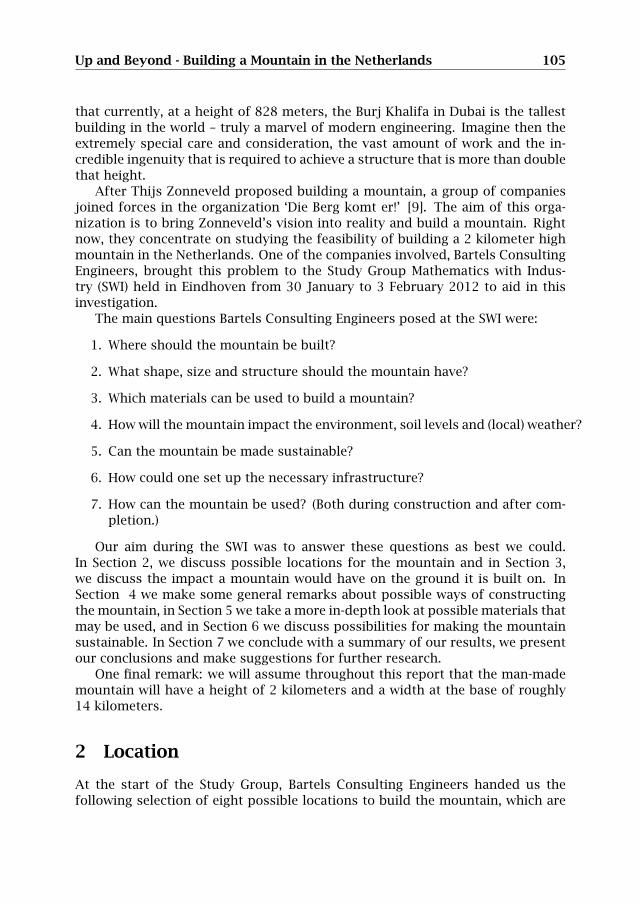
listed in the table below. The numbers in the table corresponding to the locationsare positioned on the map of the Netherlands in Figure 1.
Number of location Description In sea/on land1 near Bergen aan Zee in sea2 near The Hague in sea3 off the coast of Zeeland in sea4 off the coast of Texel in sea5 in the IJsselmeer, near the Afsluitdijk in sea6 in the IJsselmeer, close to Flevoland in sea7 in the Markermeer in sea8 in the province Flevoland on land
Figure 1: Eight possible locations to build the mountain. The numbers corre-spond to the numbers in the table of locations.
To select the most suitable location, we formulated several criteria:
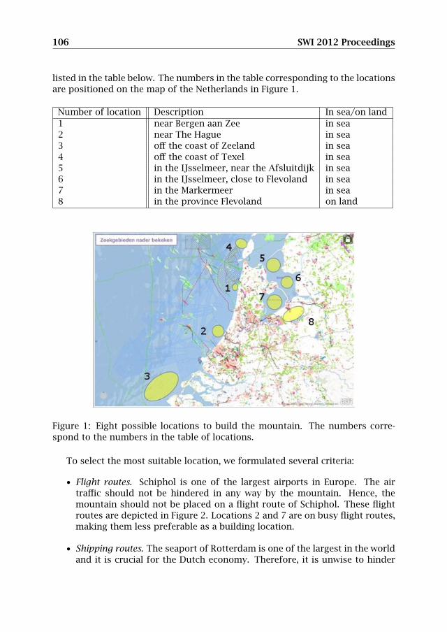
• Flight routes. Schiphol is one of the largest airports in Europe. The airtraffic should not be hindered in any way by the mountain. Hence, themountain should not be placed on a flight route of Schiphol. These flightroutes are depicted in Figure 2. Locations 2 and 7 are on busy flight routes,making them less preferable as a building location.
• Shipping routes. The seaport of Rotterdam is one of the largest in the worldand it is crucial for the Dutch economy. Therefore, it is unwise to hinder
Up and Beyond - Building a Mountain in the Netherlands 107
Figure 2: Routes of flights from and to Schiphol.
ship traffic to and from this seaport. Moreover, ships coming from the IJs-sel crossing the IJsselmeer should not be hindered either. This effectivelyrules out locations 3 and 6.
• Sea currents. The sea currents are quite strong near the North Sea coast.Building a mountain there would have a severe influence on the flow ofthese currents. This would cause changes in the location and shape ofsand banks and would cause coastal erosion. Also, the currents will putstress on the building foundations. It would need to be verified throughmodeling and simulation, but it is likely that building a mountain at lo-cation 2 would have just such an amplifying effect on the local currents.This does, however, raise the question whether the power of these currentscould be harnessed for energy production, for instance, by large turbines.Again, (computer) modeling would likely provide some insights.
• Protected environment/nature. Sustainable development and renewable en-ergy will be a key issue in this project. Naturally, the construction andplacement should have a minimal impact on the existing ecosystem, floraand fauna. Proximity of protected environments is therefore an important

108 SWI 2012 Proceedings
limiting aspect. Location 4 is close to the island of Texel, which has a richand rather unique ecosystem, and for this reason we recommend againstbuilding the mountain there.
• Accessibility. Construction resources (e.g. people, material, machines) needto efficiently reach the construction site. This is hard to assess for a givenlocation as it depends on many different factors, and needs to be looked atin more detail in future studies.
• Impact on society. Existing societal structures (e.g. cities, infrastructure)need to experience as little interference as possible from the project. Lo-cation 5, in particular, does not meet this criterium, as it is near importantinfrastructure (i.e. ‘de Afsluitdijk’).
Under these criteria, only locations 1 and 8 do not raise any immediate ob-jections: one is in sea and the other is on land, see Figure 3. As we will explainbelow in Section 3, we prefer location 1, which is in the sea near Bergen aan Zeebecause we estimate that the soil will respond rather extremely to the pressurethat the mountain would exert, and this would have less severe consequences ifthis happened off-shore.
Figure 3: The two locations that we believe are most favorable. One location isin the North Sea, about 15 km offshore near Bergen aan Zee. The other locationis on land, situated in the province Flevoland.
3 Soil mechanics
In this section we focus on the effect of the mountain on soil, by estimating howfar the mountain will sink into the ground. We also estimate how much soil willbe displaced, and whether this will cause hills or depressions to form nearby.Since these effects would likely need to be prevented, we propose some methodsto do so.
Up and Beyond - Building a Mountain in the Netherlands 109
3.1 Model
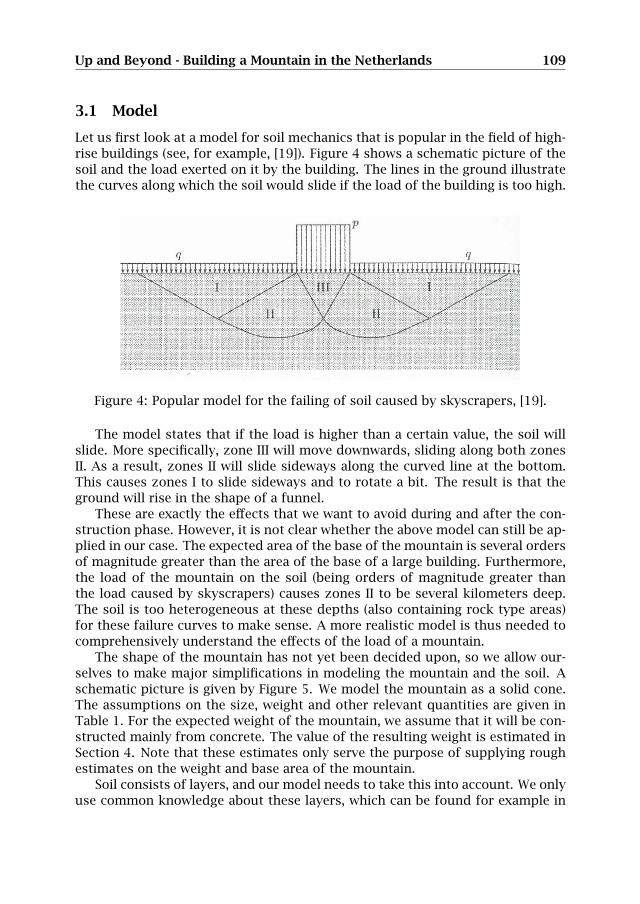
Let us first look at a model for soil mechanics that is popular in the field of high-rise buildings (see, for example, [19]). Figure 4 shows a schematic picture of thesoil and the load exerted on it by the building. The lines in the ground illustratethe curves along which the soil would slide if the load of the building is too high.
I I. I I -
is. - • •
I I. I I I~I
• -
111111K _________________
Figure 43-1. Strip foundat on
Prandtl’s solution, which will not be derived in detail here, again uses a su6di~1sionof the soil into three zones, see Figure 43-1. In zone I the horizontal ~‘tr~ss issupposed to be larger than the vertical stress, which is equal to the surcharg~ rThishorizontal stress is then the passive lateral stress corresponding to the verticái7stressq. In zone III the vertical normal stress is supposed to be the largest stress? and itsvalue is equal to the unknown load p. The transition is formed by the wedgeThapedzone II (Prandil’s wedge), which is bounded below by a logarithmic s~iral. -Theresults of the analysis can be written as .
p=cNc+qNq, 143.1)
where the coefficients N~ en Nq are dimensionless constants, for whichi4andtlobtained the following expressions,
ib~i1+sin~
Nq = exp(irtanØ), ‘(43.2)1—sin~
N~ =(NqI)cot~. (43.3)
In Table 43-1 the values of N~ and Nq are given, as a function of the friction angle 0.In the limiting case 0 = 0 the value of N~ = 2 + iv, as found in Chapter 1 .rIf,, ë = 0and • = 0 the bearing capacity must be equal to the surcharge, i.e. p = q~:rEven alayer of mud can support a certain load, provided that it is the same albover itssurface. This is expressed by the value Nq = I for ~ = 0. 1Prandtl’s formula (43.1) has been extended by Keverling Buisman, Caquot~TerzaghIand Brinch Hansen with various terms, including one for the unit weight ofith.ç soil.The complete formula is written in the form .
nil
p = cN~ + qNq + ~ 7BN7, (43.4)
Figure 4: Popular model for the failing of soil caused by skyscrapers, [19].
The model states that if the load is higher than a certain value, the soil willslide. More specifically, zone III will move downwards, sliding along both zonesII. As a result, zones II will slide sideways along the curved line at the bottom.This causes zones I to slide sideways and to rotate a bit. The result is that theground will rise in the shape of a funnel.
These are exactly the effects that we want to avoid during and after the con-struction phase. However, it is not clear whether the above model can still be ap-plied in our case. The expected area of the base of the mountain is several ordersof magnitude greater than the area of the base of a large building. Furthermore,the load of the mountain on the soil (being orders of magnitude greater thanthe load caused by skyscrapers) causes zones II to be several kilometers deep.The soil is too heterogeneous at these depths (also containing rock type areas)for these failure curves to make sense. A more realistic model is thus needed tocomprehensively understand the effects of the load of a mountain.
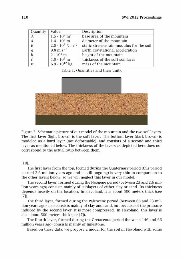
The shape of the mountain has not yet been decided upon, so we allow our-selves to make major simplifications in modeling the mountain and the soil. Aschematic picture is given by Figure 5. We model the mountain as a solid cone.The assumptions on the size, weight and other relevant quantities are given inTable 1. For the expected weight of the mountain, we assume that it will be con-structed mainly from concrete. The value of the resulting weight is estimated inSection 4. Note that these estimates only serve the purpose of supplying roughestimates on the weight and base area of the mountain.
Soil consists of layers, and our model needs to take this into account. We onlyuse common knowledge about these layers, which can be found for example in
110 SWI 2012 Proceedings
Quantity Value DescriptionA 1.5 · 108 m2 base area of the mountaind 1.4 · 104 m diameter of the mountainE 2.0 · 107 N m−2 static stress-strain modulus for the soilg 9.8 m s−2 Earth gravitational accelerationh 2 · 103 m height of the mountain` 5.0 · 102 m thickness of the soft soil layerm 6.9 · 1012 kg mass of the mountain
Table 1: Quantities and their units.
Figure 5: Schematic picture of our model of the mountain and the two soil layers.The first layer (light brown) is the soft layer. The bottom layer (dark brown) ismodeled as a hard layer (not deformable), and consists of a second and thirdlayer as mentioned below. The thickness of the layers as depicted here does notcorrespond to the actual ratio between them.
[10].The first layer from the top, formed during the Quaternary period (this period
started 2.6 million years ago and is still ongoing) is very thin in comparison tothe other layers below, so we will neglect this layer in our model.
The second layer, formed during the Neogene period (between 23 and 2.6 mil-lion years ago) consists mainly of sublayers of either clay or sand. Its thicknessdepends heavily on the location. In Flevoland, it is about 500 meters thick (see[7]).
The third layer, formed during the Paleocene period (between 66 and 23 mil-lion years ago) also consists mainly of clay and sand, but because of the pressureinduced by the second layer, it is more compressed. In Flevoland, this layer isalso about 500 meters thick (see [7]).
The fourth layer, formed during the Cretaceous period (between 146 and 66million years ago) consists mainly of limestone.
Based on these data, we propose a model for the soil in Flevoland with some
Up and Beyond - Building a Mountain in the Netherlands 111
major simplifications. We propose a two-layer system, with a soft (mobile) layerto model the Neogene layer, and a rigid (immobile) layer to model the Paleoceneand Cretaceous layer. Depending on the phenomena we want to study, we modelthe soft layer either by an incompressible viscous fluid or by an elastic mediumwith a linear stress-strain relation given by σ = Eε (see Table 1), where σ denotesthe stress and ε the strain. The value of E that we take is based upon the valuesof this modulus for soft clay and loose sand (see [12], Table 2-7 on page 99).
Since the values of E for the Paleocene and the Cretaceous layer are at leastan order of magnitude greater, we model these layers as being rigid. Hence ourmodel of the soil consists of two layers; the soft layer on top, and a rigid layerbelow (see Figure 5).
3.2 Results
First we calculate how far the mountain will sink into the soil in our model. Thisdistance is indicated by ∆`. We will model the part of the soft soil layer underthe mountain as an elastic medium for which we have the linear stress-strainrelation
σ = Eε. (1)
The stress on the soil is given by the force that the mountain exerts on the soildivided by the area: σ = F/A (for the sake of simplicity, we assume here thatthe force is equally distributed over the area). F is the gravitational force of themountain, which is given by the mass of the mountain times the gravitationalacceleration: F = mg. The strain is given by the ratio between the thickness ofthe soil and how far it is compressed: ε = ∆`/`. Substitution of these quantitiesinto (1) yields
mgA= E∆`
`.
Hence, we obtain
∆` = mg`EA
≈ 11 m, (2)
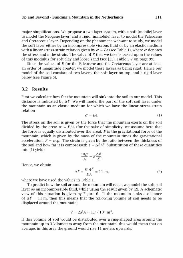
where we have used the values in Table 1.To predict how the soil around the mountain will react, we model the soft soil
layer as an incompressible fluid, while using the result given by (2). A schematicview of this situation is given by Figure 6. If the mountain sinks a distanceof ∆` = 11 m, then this means that the following volume of soil needs to bedisplaced around the mountain:
V = ∆`A ≈ 1.7 · 109 m3.
If this volume of soil would be distributed over a ring-shaped area around themountain up to 3 kilometers away from the mountain, this would mean that onaverage, in this area the ground would rise 11 meters upwards.
112 SWI 2012 Proceedings
Figure 6: Schematic picture of the situation after the mountain has sunk into thesoil. The shape of the surface of the soil in the surroundings is artificial.
3.3 Discussion
Since our model is a huge simplification of reality, our estimate that the moun-tain will sink 11 meters into the soil may be far from accurate. It is importantto enhance the model to get a more accurate estimate. The estimates can beimproved significantly by running computer simulations. This would allow oneto take into account a number of aspects that our estimates ignore, such as thefact that the load is likely not uniformly distributed, and that the soil is in realitya complex and highly heterogeneous medium.
However, suppose that our estimate of 11 meters is of the right order ofmagnitude (or too small), then major problems can be expected while buildingthe mountain. Even if one can come up with a solution that keeps the structurefrom collapsing while the mountain sinks into the soil, the problem remains thata huge amount of soil will be displaced to the surrounding area. If the mountainis going to be built on land, this could cause serious problems. If the mountainis going to be built in sea, it is still necessary to investigate whether this excessof soil can cause problems, but it seems less likely.
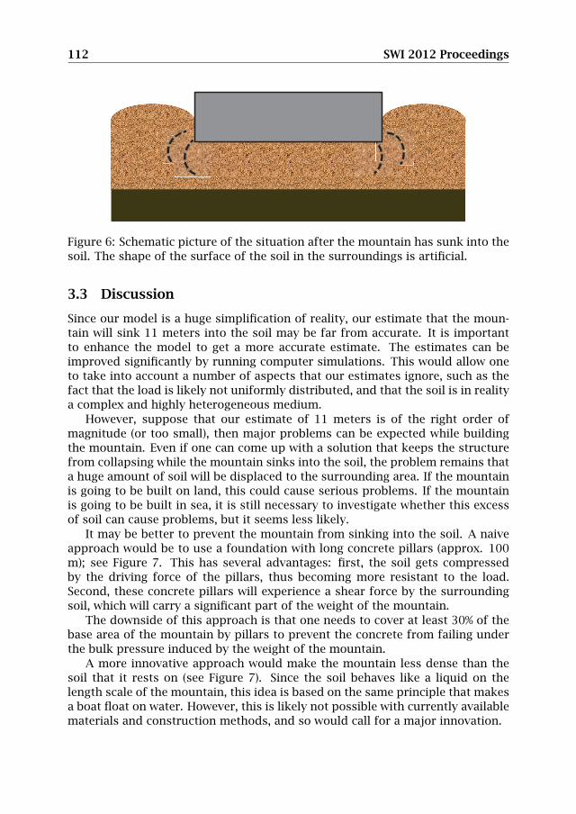
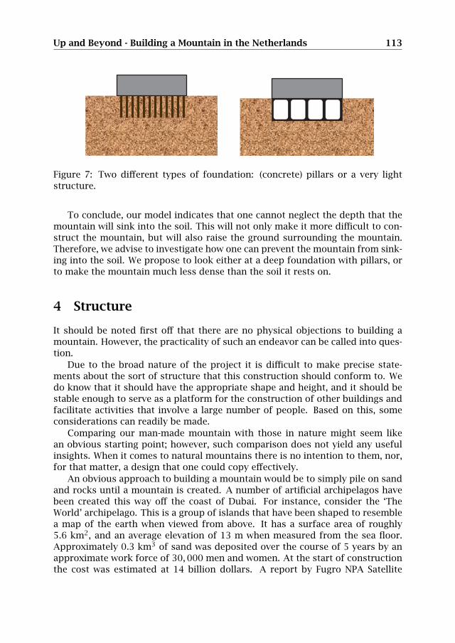
It may be better to prevent the mountain from sinking into the soil. A naiveapproach would be to use a foundation with long concrete pillars (approx. 100m); see Figure 7. This has several advantages: first, the soil gets compressedby the driving force of the pillars, thus becoming more resistant to the load.Second, these concrete pillars will experience a shear force by the surroundingsoil, which will carry a significant part of the weight of the mountain.
The downside of this approach is that one needs to cover at least 30% of thebase area of the mountain by pillars to prevent the concrete from failing underthe bulk pressure induced by the weight of the mountain.
A more innovative approach would make the mountain less dense than thesoil that it rests on (see Figure 7). Since the soil behaves like a liquid on thelength scale of the mountain, this idea is based on the same principle that makesa boat float on water. However, this is likely not possible with currently availablematerials and construction methods, and so would call for a major innovation.
Up and Beyond - Building a Mountain in the Netherlands 113
Figure 7: Two different types of foundation: (concrete) pillars or a very lightstructure.
To conclude, our model indicates that one cannot neglect the depth that themountain will sink into the soil. This will not only make it more difficult to con-struct the mountain, but will also raise the ground surrounding the mountain.Therefore, we advise to investigate how one can prevent the mountain from sink-ing into the soil. We propose to look either at a deep foundation with pillars, orto make the mountain much less dense than the soil it rests on.
4 Structure
It should be noted first off that there are no physical objections to building amountain. However, the practicality of such an endeavor can be called into ques-tion.
Due to the broad nature of the project it is difficult to make precise state-ments about the sort of structure that this construction should conform to. Wedo know that it should have the appropriate shape and height, and it should bestable enough to serve as a platform for the construction of other buildings andfacilitate activities that involve a large number of people. Based on this, someconsiderations can readily be made.
Comparing our man-made mountain with those in nature might seem likean obvious starting point; however, such comparison does not yield any usefulinsights. When it comes to natural mountains there is no intention to them, nor,for that matter, a design that one could copy effectively.
An obvious approach to building a mountain would be to simply pile on sandand rocks until a mountain is created. A number of artificial archipelagos havebeen created this way off the coast of Dubai. For instance, consider the ‘TheWorld’ archipelago. This is a group of islands that have been shaped to resemblea map of the earth when viewed from above. It has a surface area of roughly5.6 km2, and an average elevation of 13 m when measured from the sea floor.Approximately 0.3 km3 of sand was deposited over the course of 5 years by anapproximate work force of 30,000 men and women. At the start of constructionthe cost was estimated at 14 billion dollars. A report by Fugro NPA Satellite
114 SWI 2012 Proceedings
Mapping suggested that the islands were both eroding and sinking; Nakheel, thecompany in charge of development of ‘The World’, denied those claims (see [6]).
It would seem then that scaling this construction method to the size of amountain, where approximately 100 km3 of sand would have to be deposited, isnot feasible for reasons of cost and stability.
Let us then consider the scenario in which the mountain is merely a structurethat from the outside looks like a mountain, so that a comparison with a high-rise building is more appropriate.
In general, tall buildings are constructed because of their ability to providelarge usable spaces while taking up a small area at the ground level. This is quitean attractive feature for buildings to have in large cities, where space for con-struction is scarce. It is important to understand however that the motivation forbuilding exceedingly tall high-rise buildings, such as the current record holder,Burj Khalifa in Dubai, is not economical but mainly comes from the prestige thatgoes with owning (and demonstrating the ability to construct) such a tall struc-ture. It is commonly believed that construction costs grow exponentially with theheight of the building. This, put together with the extra structural precautionsrequired to make the building withstand extreme winds and earthquakes, not tomention the vast stresses and strains generated by the weight of the buildingitself, calls into question whether it is sensible or cost-effective to build so tall abuilding. Their main commonality with a man-made mountain would thereforebe that both these constructions are built mostly for their impressive height,rather than for their practicality. We thus have to ask ourselves whether thestated goals of having a structure that can both function as a mountain on theoutside and provide practical and cost-effective spaces on the interior are at allcompatible.
There are two major differences between an artificial mountain and a high-rise building. First, with an artificial mountain it is more important to have afunctional exterior than a functional interior, while with high-rise buildings itis the other way around. Whereas the facade of ordinary buildings typicallywill not contribute significantly to the total weight, with an artificial mountainone would expect its facade – e.g. the soil and secondary buildings on top ofit – to have considerable weight. The second difference is that the width-to-height aspect ratio in high-rise buildings is roughly 3:7 while for a mountainthese values would most likely be inverted. Also, high-rise buildings in generalhave vertical facades, whereas we want the facade of our artificial mountain tobe slanted, in order to use it.
The general rule with high-rise buildings, when it comes to structure, is thatabout 30% of the volume of the building is made up of structural elements suchas walls and pillars. Although it is conceivable that a clever method of construc-tion, such as a (geodesic) dome, could reduce this number in case of an artifi-cial mountain, it seems unlikely that any dramatic improvements can be made.While the lower height-to-width aspect ratio would facilitate a more widely and
Up and Beyond - Building a Mountain in the Netherlands 115
evenly distributed pressure at the base of the building, the central section of thebase, where the mountain is tallest, would have to withstand large pressures andwould therefore need to be of a higher density and be made of materials thatcould withstand extreme compressive forces. Furthermore, the surface of thestructure would have to be heavily reinforced to facilitate secondary structures,such as other buildings, roads, or simply soil and flora, natural structures likerivers and lakes, and ice formations – factors which are usually not relevant intraditional buildings. In short, it may even be optimistic to assume that only 30%of the volume of the mountain would correspond to structural elements. Thisnumber is important since it can be used to estimate the minimal volume of ma-terials needed in the construction based on an approximation of the volume ofthe mountain.
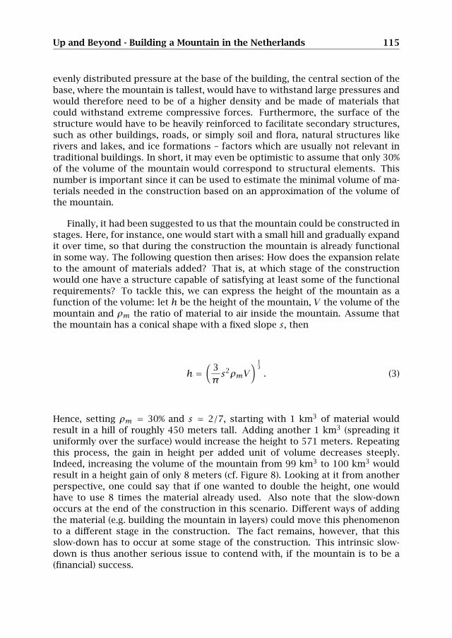
Finally, it had been suggested to us that the mountain could be constructed instages. Here, for instance, one would start with a small hill and gradually expandit over time, so that during the construction the mountain is already functionalin some way. The following question then arises: How does the expansion relateto the amount of materials added? That is, at which stage of the constructionwould one have a structure capable of satisfying at least some of the functionalrequirements? To tackle this, we can express the height of the mountain as afunction of the volume: let h be the height of the mountain, V the volume of themountain and ρm the ratio of material to air inside the mountain. Assume thatthe mountain has a conical shape with a fixed slope s, then
h =(
3πs2ρmV
) 13
. (3)
Hence, setting ρm = 30% and s = 2/7, starting with 1 km3 of material wouldresult in a hill of roughly 450 meters tall. Adding another 1 km3 (spreading ituniformly over the surface) would increase the height to 571 meters. Repeatingthis process, the gain in height per added unit of volume decreases steeply.Indeed, increasing the volume of the mountain from 99 km3 to 100 km3 wouldresult in a height gain of only 8 meters (cf. Figure 8). Looking at it from anotherperspective, one could say that if one wanted to double the height, one wouldhave to use 8 times the material already used. Also note that the slow-downoccurs at the end of the construction in this scenario. Different ways of addingthe material (e.g. building the mountain in layers) could move this phenomenonto a different stage in the construction. The fact remains, however, that thisslow-down has to occur at some stage of the construction. This intrinsic slow-down is thus another serious issue to contend with, if the mountain is to be a(financial) success.
116 SWI 2012 Proceedings
0 2000 4000 6000 8000 10 000 12 000 14 000
500
1000
1500
2000
Figure 8: Schematic of the cross section of a conical mountain for 5 km3 incre-ments with a first layer of 1 km3.
5 Materials
One of the largest limiting factors when building a mountain would be the amountof materials needed, the production costs of this material, its availability and theenvironmental impact of mining and/or manufacturing materials in such largequantities.
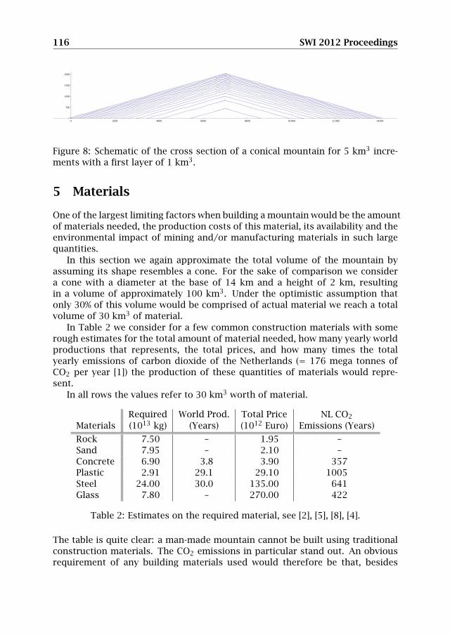
In this section we again approximate the total volume of the mountain byassuming its shape resembles a cone. For the sake of comparison we considera cone with a diameter at the base of 14 km and a height of 2 km, resultingin a volume of approximately 100 km3. Under the optimistic assumption thatonly 30% of this volume would be comprised of actual material we reach a totalvolume of 30 km3 of material.
In Table 2 we consider for a few common construction materials with somerough estimates for the total amount of material needed, how many yearly worldproductions that represents, the total prices, and how many times the totalyearly emissions of carbon dioxide of the Netherlands (= 176 mega tonnes ofCO2 per year [1]) the production of these quantities of materials would repre-sent.
In all rows the values refer to 30 km3 worth of material.
Required World Prod. Total Price NL CO2
Materials (1013 kg) (Years) (1012 Euro) Emissions (Years)
Rock 7.50 – 1.95 –Sand 7.95 – 2.10 –Concrete 6.90 3.8 3.90 357Plastic 2.91 29.1 29.10 1005Steel 24.00 30.0 135.00 641Glass 7.80 – 270.00 422
Table 2: Estimates on the required material, see [2], [5], [8], [4].
The table is quite clear: a man-made mountain cannot be built using traditionalconstruction materials. The CO2 emissions in particular stand out. An obviousrequirement of any building materials used would therefore be that, besides
Up and Beyond - Building a Mountain in the Netherlands 117
availability, they could be produced in a more-or-less CO2 neutral way. This mayvery well be the biggest hurdle when building a mountain. Note that even if ourestimated material density of 30% is off by, say, three orders of magnitude, thatis, one could build it with a material density of 0.03% instead, then this wouldstill result in the equivalent of 350 years worth of Dutch CO2 production, in themost favorable case.
To these estimates one would have to add costs, both financial and envi-ronmental, for transporting these materials. Not to mention salaries for theworkforce which would likely have to consist of tens of thousands of people, thematerial required, the costs of purchasing the land where the mountain wouldbe built and many other costs which would add significantly to the already exor-bitant numbers seen above.
Another obstacle is simply the amount of time required to finish the project;if we take the fastest material to produce from Table 2 it would take almost 40years just to produce the material, provided that one could buy 10% of all thematerial made in the world during that period.
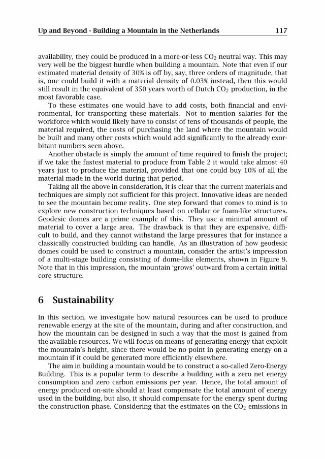
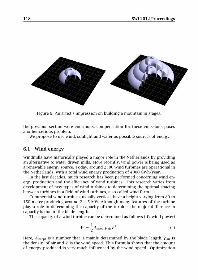
Taking all the above in consideration, it is clear that the current materials andtechniques are simply not sufficient for this project. Innovative ideas are neededto see the mountain become reality. One step forward that comes to mind is toexplore new construction techniques based on cellular or foam-like structures.Geodesic domes are a prime example of this. They use a minimal amount ofmaterial to cover a large area. The drawback is that they are expensive, diffi-cult to build, and they cannot withstand the large pressures that for instance aclassically constructed building can handle. As an illustration of how geodesicdomes could be used to construct a mountain, consider the artist’s impressionof a multi-stage building consisting of dome-like elements, shown in Figure 9.Note that in this impression, the mountain ‘grows’ outward from a certain initialcore structure.
6 Sustainability
In this section, we investigate how natural resources can be used to producerenewable energy at the site of the mountain, during and after construction, andhow the mountain can be designed in such a way that the most is gained fromthe available resources. We will focus on means of generating energy that exploitthe mountain’s height, since there would be no point in generating energy on amountain if it could be generated more efficiently elsewhere.
The aim in building a mountain would be to construct a so-called Zero-EnergyBuilding. This is a popular term to describe a building with a zero net energyconsumption and zero carbon emissions per year. Hence, the total amount ofenergy produced on-site should at least compensate the total amount of energyused in the building, but also, it should compensate for the energy spent duringthe construction phase. Considering that the estimates on the CO2 emissions in
118 SWI 2012 Proceedings
Figure 9: An artist’s impression on building a mountain in stages.
the previous section were enormous, compensation for these emissions posesanother serious problem.
We propose to use wind, sunlight and water as possible sources of energy.
6.1 Wind energy
Windmills have historically played a major role in the Netherlands by providingan alternative to water driven mills. More recently, wind power is being used asa renewable energy source. Today, around 2500 wind turbines are operational inthe Netherlands, with a total wind energy production of 4000 GWh/year.
In the last decades, much research has been performed concerning wind en-ergy production and the efficiency of wind turbines. This research varies fromdevelopment of new types of wind turbines to determining the optimal spacingbetween turbines in a field of wind turbines, a so-called wind farm.
Commercial wind turbines, usually vertical, have a height varying from 80 to150 meter producing around 2 − 5 MW. Although many features of the turbineplay a role in determining the capacity of the turbine, the major difference incapacity is due to the blade length.
The capacity of a wind turbine can be determined as follows (W : wind power)
W = 12AsweptρairV3. (4)
Here, Aswept is a number that is mainly determined by the blade length, ρair isthe density of air and V is the wind speed. This formula shows that the amountof energy produced is very much influenced by the wind speed. Optimization

Up and Beyond - Building a Mountain in the Netherlands 119
studies have shown that the ideal spacing between different turbines in a windfarm is about 12-20 times the blade length, since then the wind speed arriving ata turbine is not affected by the surrounding turbines. Thus, in order to achievethe most efficient wind energy production level, this has to be taken into accountwhen placing wind turbines in a wind farm.
Since our aim is to build a 2 km high mountain, it is worthwhile to look athow high altitudes affect the wind speed and influence the energy production,when using wind turbines. As can be seen from equation (4), the power producedis proportional to the cube of the wind speed, i.e. W ∝ V3.
The effect of altitude on wind speed can be estimated as follows (see [15]):
Vx = Vy(hxhy
)α, α ≡ 1
7(5)
Here Vy is the wind speed at a given height hy , take for example 10 meters, andVx is the wind speed at altitude hx . Formula (5) implies that at 2 km above sealevel the wind speed is approximately twice the speed at sea level (10 meters).By using relation (4) we can see that this results in eight times more energy perturbine at 2 km altitude than at sea level.
As promising as it may seem, achieving this large gain may as of yet not bepossible. Turbines constructed with today’s technology are not built to copewith very high wind speeds. Nevertheless, recent developments raise hope forproducing much more stable and strong wind turbines, see [13].
Another important aspect to consider is the stage-by-stage construction ofthe mountain. This provides the possibility to produce wind energy already af-ter the construction of the first stage. Furthermore, since wind energy is as yetnot often produced at high altitude, this way of construction will provide oppor-tunity to develop and implement the cutting-edge technology in this field.
6.1.1 Tunnels in the mountain
One of the methods for wind energy production worth considering is wind tun-neling. Making a long, relatively narrow tunnel through a building or mountainwill cause air to be sucked in at a high velocity, similar to a chimney. This methodis not widely used in traditional high-rise buildings due to stability problems, ashaving a high wind speed at the top introduces a large horizontal strain. How-ever, stability in this sense is not an issue for the mountain, because of theheight-to-width ratio is very small. Thus, tunneling appears to be a perfect wayto use the construction to generate power from wind. Studies have shown thatwind power can be increased by approximately 5-6 times with the tunneling ef-fect, see [18]. Taking into account both the effects of altitude and wind tunneling,it seems that one could generate 30 to 40 times more power from a turbine ina wind tunnel at the top of the mountain than than one could generate from atraditional wind mill at sea level of the same size as the diameter of the tunnel.
120 SWI 2012 Proceedings
6.2 Solar energy
A popular source of renewable energy is solar energy. Nowadays this is mostlycollected using photovoltaic solar panels. Of course, an enormous area such asthe surface of a mountain could easily serve as a subsoil for solar panels. Also,if the mountain would be built in layers, the panels could be installed on thefirst layer and reused in the next. This way there would be gain already in anearly stage of construction. However, it should be noted that solar panels donot seem to be significantly more efficient at high altitude than at sea level. Still,they might be implemented in places that would otherwise go unused.
Heat storage could generate energy as well, and solar radiation could con-tribute to the heating. On sunny days, heat could be collected inside or outsidethe structure. We now discuss some possibilities to use heat in more detail.
6.2.1 Solar chimneys
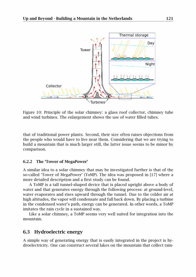
A number of new techniques in renewable energy have been developed over theyears, one of them is a so-called ‘solar chimney’, an installation which combinesthree simple techniques. It consists of three essential elements: a glass roof, achimney and wind turbines. Basically, this construction works as follows. Solarradiation heats up air below the glass roof with open sides. Attached to this roofis a high chimney. Air at large altitudes is cooler, and the difference in tempera-ture of the air below the glass roof and at the top of the chimney causes the hotair to rise, creating a draft within the chimney. This principle of air accelerationcauses high wind speeds which can generate energy using wind turbines (seeFigure 10).
To have an effective solar chimney, a large area at ground level should be cov-ered by a transparent roof, so as to catch as much heat from the sun as possible.A single 1000 meter tall solar chimney can provide energy for 30,000 Dutchhouseholds, see [16] (see also [3], [14] for further literature on solar chimneys).
Using solar chimneys has several advantages compared to other energy sour-ces. For instance, since it uses both direct and diffuse radiation it is more suitedto the Dutch weather conditions, whereas traditional solar power plants can onlyuse direct radiation, which means they only work on sunny days. Also, becausethe construction of a solar chimney is relatively simple and there are few movingparts, the structure is very reliable (and therefore it requires little maintenance).Moreover, the power plant needs no cooling water, which is commonly usedin solar power plants today. The greatest advantage, however, is that all thenecessary technologies are already widely available and relatively cheap.
In 1982, a prototype solar chimney was built in Manzanares, Spain. It is a195 m high chimney with a diameter of 10 m, with a collector that is 244 min diameter. It achieved a yield of 50 kW. Designs for chimneys with a yield of100 MW exist. Until now these chimneys have not often been used. There are tworeasons for this. First, the efficiency of a solar chimney is fairly low compared to
Up and Beyond - Building a Mountain in the Netherlands 121
Figure 10: Principle of the solar chimney: a glass roof collector, chimney tubeand wind turbines. The enlargement shows the use of water filled tubes.
that of traditional power plants. Second, their size often raises objections fromthe people who would have to live near them. Considering that we are trying tobuild a mountain that is much larger still, the latter issue seems to be minor bycomparison.
6.2.2 The ‘Tower of MegaPower’
A similar idea to a solar chimney that may be investigated further is that of theso-called ‘Tower of MegaPower’ (ToMP). The idea was proposed in [17] where amore detailed description and a first study can be found.
A ToMP is a tall tunnel-shaped device that is placed upright above a body ofwater and that generates energy through the following process: at ground-level,water evaporates and rises upward through the tunnel. Due to the colder air athigh altitudes, the vapor will condensate and fall back down. By placing a turbinein the condensed water’s path, energy can be generated. In other words, a ToMPimitates the rain cycle in a sustained way.
Like a solar chimney, a ToMP seems very well suited for integration into themountain.
6.3 Hydroelectric energy
A simple way of generating energy that is easily integrated in the project is hy-droelectricity. One can construct several lakes on the mountain that collect rain-
122 SWI 2012 Proceedings
water. These lakes can be used to store and produce energy, but could alsoprovide venues for recreation. The lakes can be constructed at different alti-tudes. This way, a surplus of generated energy can be stored by pumping upwater from one lake to another, higher up the mountain. This energy can thenlater be reclaimed by using a hydroelectric power installation. This way, thesystem functions a lot like a battery. Apart from using the water to store andgenerate energy, this water can also be used in various ways to supply the needsof the mountain’s facilities.
7 Summary, conclusions and recommendations
We have taken on the challenge posed by Bartels Consulting Engineers duringthe Study Group Mathematics with Industry in Eindhoven, the Netherlands, andinvestigated both the possibilities of and the difficulties in constructing a 2 kilo-meter tall artificial mountain in the Netherlands.
Where to build a mountain. The Netherlands is a relatively small but denselypopulated country. The mountain would have to be built in an uninhabited zone.This clearly creates a severe restriction. We considered eight possible locationssuggested by the organization of ‘Die Berg komt er!’, and came to the conclusionthat it is best to either build it on land in the province of Flevoland, or to build itin the North Sea near (the appropriately named) Bergen aan Zee. We chose theselocations on the basis of several criteria imposed by the presence of settlements,industry, infrastructure and nature.
Another important factor to take into account when choosing a location is theeffect such a massive structure would have on the underlying soil, and specifi-cally on the areas around it.
Of the two locations that seem the most convenient, we believe that the moun-tain would best be placed in sea rather than on land, considering the effects thebuilding of a mountain would have on the surrounding soil, as the soft Dutchsoil would shift significantly under the load of a mountain. In fact, we estimatedthat without a proper foundation the mountain could sink as much as 11 metersinto the ground, and that this displacement would result in raising the groundaround the mountain on average by 11 meters as far as 3 kilometers away.
Furthermore, we conclude that to minimize the effects of the mountain on thesurrounding soil, it would be best to come up with a method that would preventthe mountain from sinking at all. The traditional way would require many andlong concrete pillars to be driven into the soil; alternatively, one could lower theaverage density of the mountain, for instance by building it on a cushion madeof a very light material, so that the mountain floats on the soil, like a ship in thewater.
We recommend that extensive measurements of the profile of the soil layersis performed, down to much greater depths than is standard practice. This data
Up and Beyond - Building a Mountain in the Netherlands 123
can be used in a computer model to assess the ramifications on the surroundingsoil (and possibly, sea currents) and the structural requirements in much greaterdetail than we were able to, in a couple of days.
How to build a mountain. Building a 2 kilometer high mountain would be anendeavor of unprecedented scale in human history. Comparison to existing man-made archipelagos tell us that a solid mountain made of sand and rocks wouldcost too much, erode too easily, and involve too much work to be completed in afeasible amount of time. This leads us to conclude that instead one would needto apply more refined construction techniques that allow for rapid progress andthat require significantly less material than a solid mountain would.
In Section 4 we presented a table that states for a number of common buildingmaterials the total price, a comparison of the necessary amount with the currentworld production, and a comparison with the total annual emission of CO2 inthe Netherlands. These estimates give us a strong indication that not enough ofthese materials is available (in the world) to finish the project on a time scaleof decades. Furthermore, even if availability was not a problem, the productionof these materials would be far too damaging for the (global) environment to bejustifiable. Thus, we have to conclude that with the materials and techniquesthat are currently common, a 2 kilometer high mountain cannot be built.
Hence, the problem of producing massive quantities of cheap building mate-rials without producing large amounts of CO2 or other pollutants must first beresolved before a mountain can be built. This is certainly the most important anddifficult problem that comes with building a mountain, but also the one wherethe reward is the greatest.
How to make the mountain sustainable. The mountain can be designed insuch a way that electrical energy can be generated in several ways. Some modernideas like a ‘Tower of MegaPower’, wind tunnels through the mountain and solarchimneys seem good candidates, since the mountain is very susceptible to theintegration of such devices. Indeed, the integration of devices that rely on thedifference in temperature at the ground and at greater altitude, or on the higherwind speeds that come with greater altitude, seem to offer the greatest rewards.
Summary. With the current techniques, materials and knowledge it is not pos-sible to build a 2 kilometer high mountain. It seems that vast leaps in thinkingabout structural design and material use have to be made: the mountain needsto be as light as possible, as cheap as possible, as ‘clean’ as possible, and it needsto be built in a relatively short time as well. This opens up grand new challengesin material development, design and logistics.
As for the sustainability of the project, there are certainly many ways in whichthe mountain can be used to generate clean energy.
124 SWI 2012 Proceedings
The building of a mountain in the Netherlands turns out to be both challeng-ing and inspiring; it certainly invites one to go up and beyond.
8 Acknowledgments
We would like to thank Bartels Consulting Engineers and in particular ir. SigridMulders for participating in the Study Group Mathematics with Industry andproposing this wonderful challenge. During the week, we consulted experts inseveral fields. Thanks are due to prof.dr.ir. Bert Blocken, dr.ir. Hans Hoen-derkamp, ir. Rijk Blok and ir. Juan Manuel Davila Delgado for their time andeffort.
References
[1] http://statline.cbs.nl/statweb/publication/?vw=t&dm=slnl&pa=70946ned&d1=a&d2=0-1,15&d3=a&hd=121112-1143&hdr=t&stb=g1,g2.
[2] http://minerals.usgs.gov/minerals/pubs/commodity/cement/index.html.
[3] http://www.floatingsolarchimney.gr/.
[4] http://ec.europa.eu/enterprise/sectors/metals-minerals/non-metallic-mineral-products/glass/index_en.htm.
[5] http://en.wikipedia.org/wiki/plastic#production_of_plastics.
[6] http://www.telegraph.co.uk/news/worldnews/middleeast/dubai/8271643/the-world-is-sinking-dubai-islands-falling-into-the-sea.html.
[7] http://www.geologievannederland.nl/boorprofiel.
[8] http://en.wikipedia.org/wiki/list_of_countries_by_steel_production.
[9] http://www.diebergkomter.nl/.
[10] http://en.wikipedia.org/wiki/geologic_time_scale.
[11] http://www.nu.nl/column-vrijdag/2604966/berg-onzin.html.
[12] J. E. Bowles. Foundation Analysis and Design. S.l.: McGraw-Hill, 1977.
[13] G. G. H. D. GmbH. Market status of high altitude wind energy.http://www.gl-garradhassan.com/en/highaltitudewind.php/, 2011.
[14] C. D. Papageorgiou. Floating solar chimney technology for eu and mediter-ranean countries. Unpublished, 2009.
Up and Beyond - Building a Mountain in the Netherlands 125
[15] E. Peterson and J. Hennessey. On the use of power laws for estimates ofwind power potential. Journal for Applied Meteorology, 17:390–394, 1978.
[16] S. B. und Partner. The solar chimney. Unpublished, 2002.
[17] R. van Ginkel, F. Hoos, R. Krom, and P. van Summeren. Torenvan 5 km in Noordzee voor opwekken energie. De Ingenieur, 20:http://www.lgwkater.nl/energie/index1.htm, 1995.
[18] T. Van Hooff, B. Blocken, L. Aanen, and B. Bronsema. A venturi-shaped rooffor wind-induced natural ventilation of buildings: Wind tunnel and CFDevaluation of different design configurations. Building and Environment,46:1797–1807, 2011.
[19] A. Verruijt and S. van Baars. Soil Mechanics. Delft : VSSD, 2007.