uop5 manual - issue 18
TRANSCRIPT

8/10/2019 UOP5 Manual - Issue 18
http://slidepdf.com/reader/full/uop5-manual-issue-18 1/52
INSTRUCTION MANUAL
UOP5
LIQUID/LIQUID EXTRACTION UNIT
UOP5

8/10/2019 UOP5 Manual - Issue 18
http://slidepdf.com/reader/full/uop5-manual-issue-18 2/52

8/10/2019 UOP5 Manual - Issue 18
http://slidepdf.com/reader/full/uop5-manual-issue-18 3/52
ARMFIELD LIMITED
OPERATING INSTRUCTIONS AND EXPERIMENTS
UOP5 - LIQUID/LIQUID EXTRACTION UNIT
Page No.
SAFETY IN THE USE OF EQUIPMENT SUPPLIED BY ARMFIELD 1
INTRODUCTION 6
RECEIPT OF EQUIPMENT 7
DESCRIPTION 8
ASSEMBLY 15
CONNECTION TO SERVICES 17
COMMISSIONING 19
ROUTINE MAINTENANCE 22
INDEX TO EXPERIMENTS 26
SOLVENT/SOLUTE SYSTEMS FOR USE WITH UOP5 ii
CALIBRATING THE SOLVENT METERING PUMP iii
GENERAL SAFETY RULES a
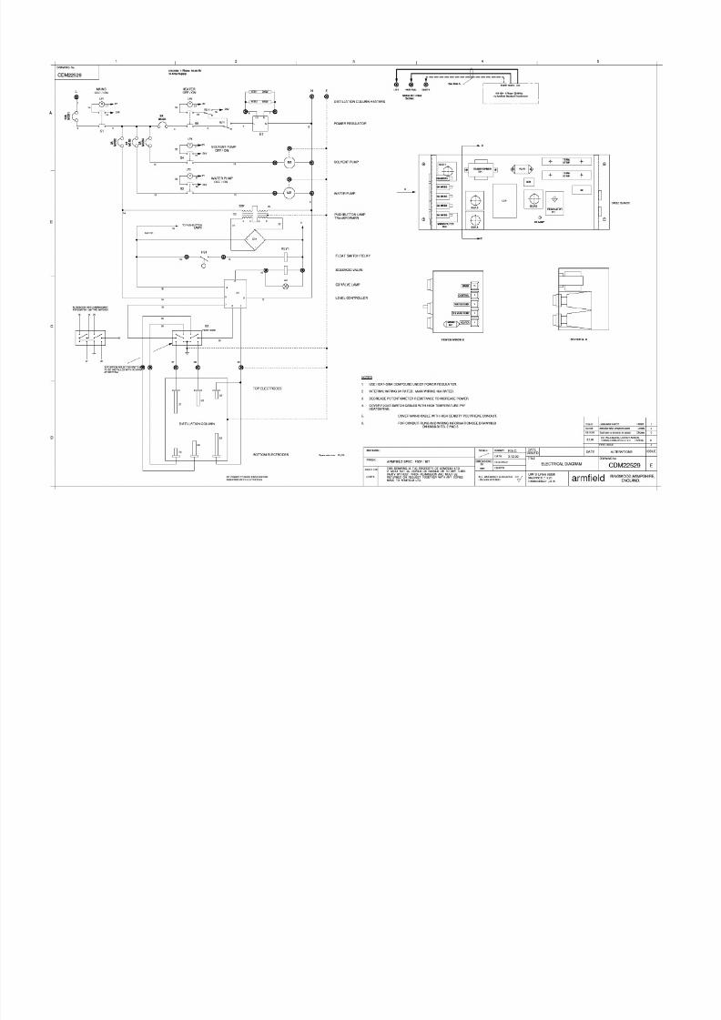
ELECTRICAL DIAGRAM CDM22529 Appendix

8/10/2019 UOP5 Manual - Issue 18
http://slidepdf.com/reader/full/uop5-manual-issue-18 4/52

8/10/2019 UOP5 Manual - Issue 18
http://slidepdf.com/reader/full/uop5-manual-issue-18 5/52
SAFETY IN THE USE OF EQUIPMENT SUPPLIED BY ARMFIELD
Before proceeding to install, commission or operate the equipment describedin this instruction manual we wish to alert you to potential hazards so thatthey may be avoided.
Although designed for safe operation, any laboratory equipment may involveprocesses or procedures which are potentially hazardous. The major potentialhazards associated with this particular equipment are listed below.
INJURY THROUGH MISUSE
INJURY FROM ELECTRIC SHOCK
INJURY FROM INCORRECT HANDLING
POISONING FROM TOXIC MATERIALS
INJURY FROM CORROSIVE LIQUIDS
RISK OF INFECTION THROUGH LACK OF CLEANLINESS
DAMAGE TO CLOTHING
Accidents can be avoided provided that equipment is regularly maintained and staff and students are made aware of potential hazards. A list of generalsafety rules is included in this manual, to assist staff and students in thisregard. The list is not intended to be fully comprehensive but for guidanceonly.
Please refer to the notes overleaf regarding the Control of SubstancesHazardous to Health Regulations.

8/10/2019 UOP5 Manual - Issue 18
http://slidepdf.com/reader/full/uop5-manual-issue-18 6/52
The COSHH Regulations
The Control of Substances Hazardous to Health Regulations (1988)
The COSHH regulations impose a duty on employers to protect employees and others
from substances used at work which may be hazardous to health. The regulations
require you to make an assessment of all operations which are liable to expose any
person to hazardous solids, liquids, dusts, vapours, gases or micro-organisms. You are
also required to introduce suitable procedures for handling these substances and keep
appropriate records.
Since the equipment supplied by Armfield Limited may involve the use of substances
which can be hazardous (for example, cleaning fluids used for maintenance or
chemicals used for particular demonstrations) it is essential that the laboratory
supervisor or some other person in authority is responsible for implementing the
COSHH regulations.
Part of the above regulations are to ensure that the relevant Health and Safety Data
Sheets are available for all hazardous substances used in the laboratory. Any person
using a hazardous substance must be informed of the following:
Physical data about the substance
Any hazard from fire or explosion
Any hazard to health
Appropriate First Aid treatment
Any hazard from reaction with other substances
How to clean/dispose of spillage
Appropriate protective measures
Appropriate storage and handling
Although these regulations may not be applicable in your country, it is strongly
recommended that a similar approach is adopted for the protection of the students
operating the equipment. Local regulations must also be considered.
Water-Borne Infections
The equipment described in this instruction manual involves the use of water which
under certain conditions can create a health hazard due to infection by harmful micro-
organisms.

8/10/2019 UOP5 Manual - Issue 18
http://slidepdf.com/reader/full/uop5-manual-issue-18 7/52
Under the COSHH regulations, the following precautions must be observed:-
Any water contained within the product must not be allowed to stagnate, i.e. the water
must be changed regularly.
Any rust, sludge, scale or algae on which micro-organisms can feed must be removed
regularly, i.e. the equipment must be cleaned regularly.
Where practicable the water should be maintained at a temperature below 20°C or
above 45°C. If this is not practicable then the water should be disinfected if it is safe
and appropriate to do so. Note that other hazards may exist in the handling of biocides
used to disinfect the water.
A scheme should be prepared for preventing or controlling the risk incorporating all of
the actions listed above.
Further details on preventing infection are contained in the publication “The Control
of Legionellosis including Legionnaires Disease” - Health and Safety Series booklet
HS (G) 70.

8/10/2019 UOP5 Manual - Issue 18
http://slidepdf.com/reader/full/uop5-manual-issue-18 8/52
USE OF A RESIDUAL CURRENT DEVICE FOR ELECTRICAL SAFETY
The equipment described in this Instruction Manual operates from a mains voltage
electrical supply. The equipment is designed and manufactured in accordance with
appropriate regulations relating to the use of electricity. Similarly, it is assumed that
regulations applying to the operation of electrical equipment are observed by the end
user.
However, it is recommended that a Residual Current Device (RCD) alternatively
called an Earth Leakage Circuit Breaker (ELCB) be fitted to this equipment. If
through misuse or accident the equipment becomes electrically dangerous, an RCD
will switch off the electrical supply and reduce the severity of any electric shock
received by an operator to a level which, under normal circumstances, will not cause
injury to that person.
If the electrical supply to the laboratory already incorporates an RCD, then the device
supplied with the equipment need not be used. If the electrical supply does not
incorporate such protection then the loose RCD supplied by Armfield Ltd should be
fitted by a competent electrician either in the supply to the laboratory or in the supply
to the individual item of equipment. Drawing Number BM20491 gives full
installation instructions.
Note: If any doubt exists whether the electrical supply incorporates a device then the
RCD supplied should be fitted.
At least once each month, check that the RCD is operating correctly by pressing the
TEST button. The circuit breaker MUST trip when the button is pressed. Failure to
trip means that the operator is not protected and the equipment must be checked andrepaired by a competent electrician before it is used.

8/10/2019 UOP5 Manual - Issue 18
http://slidepdf.com/reader/full/uop5-manual-issue-18 9/52
1 3
2 4
Clip
To equipment
Off position
L i v e ( B r o w
n )
N e u t r a l ( B l
u e )
E a r t h ( G r e e n / Y e l l o w )
Remove 130mm outer sheath, cutLive (brown) & Neutral (blue)
NOT EARTH (green/yellow)
from
BM20491
1.
Ensure equipment is disconnected from
electrical supply
2. Locate suitable position for RCD on oradjacent to equipment
3. Remove cover from mounting base
4. Position base, mark off, drill through 2holes
5. Fix base at location using suitable
screws6. Fix RCD to base
7. Remove 130mm of outer sheath of
cable in line with RCD8. Cut live and neutral, connect to RCD.
Do not cut earth.
9. Fit cover to base and RCD
10. Reconnect main power supply
11. Switch on RCD
L i v e
N e u t r a l
E a r t h

8/10/2019 UOP5 Manual - Issue 18
http://slidepdf.com/reader/full/uop5-manual-issue-18 10/52
INTRODUCTION
Many processes in chemical engineering require the separation of one or more of the
components of a liquid mixture by treating the mixture with an immiscible solvent in
which these components are preferentially soluble. In some cases purification of a
liquid may be the function of the process, in others the extraction of a dissolved
component for subsequent processing may be the important aspect. An example of the
former is the preparation of pure organic liquids from products of the oil industry.
Liquid/liquid extractions may also be used as energy-saving processes by, for
example, eliminating distillation stages. It is possible, of course that the substance of
interest may be heat-sensitive anyway and that distillation is accordingly an
unacceptable process.
The rate at which a soluble component is transferred from one solvent to another will
be dependent, amongst other things on the area of the interface between the two
immiscible liquids. Therefore it is very advantageous for this interface to be formed
by droplets and films, the situation being analogous to that existing in packed
distillation columns.
The Armfield Liquid/Liquid Extraction Unit takes the form of a vertically-orientedpacked column which may be operated either, by filling the column with water and
allowing a solvent to flow down the column over the packing, or filling the column
with solvent and allowing water to flow up the column over the packing. In either case
the process is continuous, both liquids being pumped into the column. Sensing
electrodes at the top and bottom of the column determine whether the column is filled
with water or with solvent. This is achieved by sensing and maintaining the position
of the water level at the appropriate height. A solenoid valve controlling the flow of
solvent under gravity from the column is operated by the sensing electrode system.
A distillation unit with a fractionating column is included to allow the reclamation of
solvent where appropriate.

8/10/2019 UOP5 Manual - Issue 18
http://slidepdf.com/reader/full/uop5-manual-issue-18 11/52
RECEIPT OF EQUIPMENT
1. SALES IN THE UNITED KINGDOM
The apparatus should be carefully unpacked and the components checked against the
Advice Note. A copy of the Advice Note is supplied with this instruction manual for
reference.
Any omissions or breakages should be notified to Armfield Ltd within three days of
receipt.
2. SALES OVERSEAS
The apparatus should be carefully unpacked and the components checked against the
Advice Note. A copy of the Advice Note is supplied with this instruction manual for
reference.
Any omissions or breakages should be notified immediately to the Insurance Agent
stated on the Insurance Certificate if the goods were insured by Armfield Ltd.
Your own insurers should be notified immediately if insurance was arranged by
yourselves.

8/10/2019 UOP5 Manual - Issue 18
http://slidepdf.com/reader/full/uop5-manual-issue-18 12/52
DESCRIPTION
All numerical references relate to the Equipment Diagram on page 11 and the
Component System Diagram on page 12 and in the experimental section of this
manual.
All letter coded references relate to the Control and Instrumentation System Diagram
on page 13 and in the experimental section of this manual.
The equipment is mounted in a floor-standing, welded steel framework (8) fitted with
adjustable feet (12). The frame contains an extra cross-member (9) at the front and a
similar one at the rear to allow the use of a fork-lift truck.
The glass liquid/liquid extraction column (19a & 19b) is fitted with enlarged end
sections (14), (25), which are closed by stainless steel plates (13), (26), the lower one
being bolted to the framework and supporting the column. The four sections of the
column proper and the two end plates are all fastened together with flanges (15), the
joints between the sections being sealed with moulded PTFE gaskets. The column is
filled with Raschig rings which are supported on a perforated stainless steel plate (16)
fitted between the bottom enlarged portion and the lower section of the column.
Water for the column is stored in the supply tank (37) (L2) from where it is pumped
by the centrifugal pump (4), through an air bleed valve (5) (V3), a flow control valve
(23) (C1) and a flowmeter (24) (F1) to an injector (28) mounted in the baseplate and
with its exit about 150mm above the plate. Water leaves the top of the column
through a pipe, and is collected in a polythene tank (40) (L1).
All storage tanks for solvent are constructed in stainless steel. The organic solventsupply tank (3) (L5) provides the feed for the solvent metering pump (43) (F2), the
pumping rate of which is varied by a stroke adjustment knob (1) and indicated by a
dial calibrated from 1 – 10 where 10 is the maximum flow (nominally 380ml/min at
50Hz). Pumped solvent enters the top of the column via an injector similar to that
fitted at the base for the water (28). A sampling and drain cock (2) (V6) is fitted in the
solvent feed line.
NOTE: The stroke adjustment knob on the metering pump must only beadjusted when the pump is running. The smaller clamping knob must be
unscrewed before making an adjustment then tightened again when the
adjustment knob is in the required position (scale is calibrated 1 – 10).
A 3-way valve (V8) at the discharge of the solvent pump allows the flow from the

8/10/2019 UOP5 Manual - Issue 18
http://slidepdf.com/reader/full/uop5-manual-issue-18 13/52
Solvent from the base of the column is returned under gravity to the receiver vessel
(36) (L3) via a pipeline (27) which is also fitted with a solenoid valve (6) (C3) and a
sampling cock (V9).
The level of the water/solvent interface in the column is determined by the operation
of the solenoid valve (6) (C3) in the solvent outlet pipeline. The operation of this
valve is controlled by water-sensing electrodes, one set fitted to the top plate (31) and
another set to the bottom plate (11). A switch (S2) on the system control panel (34)
(see also diagram of the panel) selects the electrodes in use and hence determines
whether the interface is at the top or bottom of the column. Each electrode set consists
of three stainless steel electrodes, a bare earth electrode to make continuous contact
with the water and two others of different lengths insulated to points 5mm from theirends. These insulated electrodes are set to heights differing by 5mm which produces a
liquid level differential of 5mm.
The purpose of this arrangement is to avoid frequent opening and closing of the
solenoid valve which would occur with a simple single-electrode system. The
electrical sensing system operates at a low AC voltage and the conduction current
through the water is small, the latter being translated into a solenoid-operating voltage
by a plug-in module behind the control panel.
The receiver vessel (36) (L3) may be connected to the solvent supply vessel via a
pipeline and a valve (38) (V4). Thus, liquid which has passed through the column
once may be treated again in a batch wise fashion or the valve (38) (V4) may be left
open during the extraction to provide a closed circuit, the solvent then being re-
circulated continuously.
The distillation column boiler (20) (L6), mounted behind the extraction column, isfitted at such a height that liquid may be drained into it from the upper of the three
solvent tanks and can be drained from it into the lowest tank. The valve (18) (V7)
controls the release of solvent into the boiler. Like pipework, valves and fittings, the
boiler is constructed in stainless steel. Heating is by means of two 500W cartridge
elements inserted at the base of the boiler and boiler temperature is indicated on a
thermometer in the side. The boiler lid is perforated where the distillation column is
fitted (35) and three blind tapped holes around this area accept bolts fixing the column
flange to the boiler.
The column proper is made up of a glass section (22) containing four sieve plates. The
glass reflux divider (33) bolts to the column top and to the stainless steel condenser
above it with bolts and flanges and all the sections are sealed together with moulded
PTFE gaskets.

8/10/2019 UOP5 Manual - Issue 18
http://slidepdf.com/reader/full/uop5-manual-issue-18 14/52
Condensate from the reflux divider flows under gravity into the middle solvent tank
(39 (L4) via the flow control valve (17) (C2) which thus determines the reflux ratio.
The contents of the middle tank (39) (L4) can be drained into the solvent supply tank
by opening the valve (41) (V5) between the two.
The three solvent tanks (36) (L3), (39) (L4), (3) (L5) are vented to atmosphere through
a vent pipe which is inserted into the top of the condenser. Solvent levels in the tanks
and boiler are indicated with glass sight tubes protected by clear polyethylene sleeves.
Control of the equipment is simplified with a system diagram panel (34) shown in
detail on page 12. The complete solvent/water flow system is shown with electricalcontrols at the appropriate points on the diagram. These are mains on/off switch (S1),
water pump on/off switch (S3), solvent pump on/off switch (S4), boiler heater switch
(S5) and power regulator (R1), electrode changeover switch (S2), and solenoid valve
'open' indicator light. The four mains supply switches are self-illuminating in the 'on'
position. A mains transformer (42) is supplied when the electrical supply is 120V,
60Hz A.C.

8/10/2019 UOP5 Manual - Issue 18
http://slidepdf.com/reader/full/uop5-manual-issue-18 15/52

8/10/2019 UOP5 Manual - Issue 18
http://slidepdf.com/reader/full/uop5-manual-issue-18 16/52

8/10/2019 UOP5 Manual - Issue 18
http://slidepdf.com/reader/full/uop5-manual-issue-18 17/52

8/10/2019 UOP5 Manual - Issue 18
http://slidepdf.com/reader/full/uop5-manual-issue-18 18/52
INSTALLATION REQUIREMENTS
ELECTROMAGNETIC COMPATIBILITY
This apparatus is classified as Education and Training Equipment under the
Electromagnetic Compatibility (Amendment) Regulations 1994. Use of the apparatus
outside the classroom, laboratory or similar such place invalidates conformity with the
protection requirements of the Electromagnetic Compatibility Directive (89/336/EEC)
and could lead to prosecution.
FACILITIES REQUIRED
The equipment is floor mounted and requires a level area that is capable of supporting
the weight of the equipment.
A single phase A.C. mains electricity supply is required for connection to the
equipment via the attached cable. The mains plug fitted will depend on the version
supplied to suit the local electrical supply.
Three versions of the UOP5 are available: -
UOP5-A 220/240V/1ph/50Hz, fused @ 10 Amps – mains lead
fitted with 2 pin Shuko plug (European) with 3 pin
adaptor (UK)
UOP5-B 110/120V/1ph/60Hz, fused @ 15 Amps – supplied with
separate transformer fitted with NEMA 5-15P plug
(125V USA)
UOP5-G 220V/1ph/60Hz, fused @ 10 Amps – mains lead fitted
with NEMA 6-15P plug (250V USA)
Note: Version UOP5-B is supplied with a loose transformer to step-up the 120V
supply to 230V to suit the equipment. The transformer should be sited adjacent to the
120V mains outlet socket in the laboratory, in a dry location. The mains lead from the
UOP5 is simply plugged into the 230V 3 pin outlet socket on the front of the
transformer.
A cooling water supply is required for the condenser of up to 5 litres/minute at 1 barg
pressure. The water supply should be connected using 12.7 mm (0.5”) I.D. reinforced
flexible hose (not supplied). The water exiting the condenser should be led to a
suitable drain using similar hose.

8/10/2019 UOP5 Manual - Issue 18
http://slidepdf.com/reader/full/uop5-manual-issue-18 19/52
ASSEMBLY
All numerical references relate to the diagram on page 11.
All alpha numeric references relate to the diagram on page 13
1. Locate the framework in the desired location following the recommendations
in 'Installation Requirements'. Care should be exercised if using a fork-lift or
other lifting tackle to install the equipment as pipework and components are
exposed at the base of the equipment.
2. Disconnect all pipework connections to the top plate (26) on the extractioncolumn. Disconnect the three level electrodes from the top plate noting relative
positions.
3. Remove the top extraction column supporting bracket. Remove the top plate
from the extraction column by removing the six nuts and bolts.
4. Three-quarters fill the column with clean water using a bucket or hose pipe.
5. Load 0.1 litres of 15mm diameter Raschig rings followed by 2.4 litres of
10mm Raschig rings into the column. Until the level of rings reaches the top
white P.T.F.E. gasket situated between the thin and enlarged sections of the
column.
6. Drain all water from the extraction column by opening the drain cock V11 in
the base of the column
7. Replace the top plate on the extraction column. Ensure the sealing gasket is
correctly fitted. Tighten the six nuts and bolts. Replace the column supporting
bracket.
8. Replace the electrodes, connecting wires and pipework connections (Details
about the connections to the electrodes are included in the Routine
Maintenance section of this instruction manual).
9. Connect the 3 way stainless steel valve V8 (complete with pipework and
sample valve (V13) between the discharge connection on the solvent pump
and the pipework to the injector on the top plate of the extraction column.
10. Attach the pre-bent vent pipe to the spare stud coupling located on the top

8/10/2019 UOP5 Manual - Issue 18
http://slidepdf.com/reader/full/uop5-manual-issue-18 20/52
12. Carefully tighten all couplings on the extraction column and distillation
column, applying equal tension to each bolt.
To avoid distorting the P.T.F.E. sealing ring between the couplings, the topand especially the base of the column - do not over-tighten sealing bolts and
washers.
13. Locate the glass thermometer (T2) (30) in the branch of the reflux divider.
Tighten the nylon union.
NOTE: Ensure that behind the silicone seal on the solvent side a P.T.F.E.
washer is fitted to protect the silicone against the solvent.
14. Remove the oil filler plug from the top of the gearbox on the solvent pump and
fill the gearbox with the oil supplied (General Gear Lubricant type 85W140).
Check that the level is coincident with the mark on the dip stick then replace
the filler plug and dip stick.

8/10/2019 UOP5 Manual - Issue 18
http://slidepdf.com/reader/full/uop5-manual-issue-18 21/52
CONNECTION TO SERVICES
ELECTRICAL SUPPLY FOR VERSION UOP5-A:
This version of the equipment requires connection to a single phase, fused electrical
supply. The standard electrical supply for this equipment is 230V, 50Hz. Check that
the voltage and frequency of the electrical supply agree with the label attached to the
supply cable on the equipment.
The Shuko 2 pin plug can be connected directly to European style mains outlet
sockets. The 3 pin adaptor should be fitted to the Shuko plug when connecting the
equipment to 3 pin UK style sockets.
When installing the equipment it will not be necessary for an electrician to terminate
any bare electrical connections but for information the supply cable and electrical
wiring on the UOP5 uses the following convention:-
GREEN/YELLOW - EARTH
BROWN - LIVE (HOT)
BLUE - NEUTRAL
Fuse Rating - 10 AMP
ELECTRICAL SUPPLY FOR VERSION UOP5-B:
The equipment requires connection to a single phase, fused electrical supply. The
standard electrical supply for this equipment is 120V, 60Hz. Check that the voltage
and frequency of the electrical supply agree with the label attached to the supply cable
on the equipment.
This version of the UOP5 is supplied with a loose transformer to step-up the 120Vsupply to 230V to suit the equipment. The transformer should be located adjacent to
the 120V mains outlet socket in the laboratory, in a dry location. The mains lead from
the UOP5 is simply plugged into the 230V outlet socket on the front of the
transformer. The NEMA 5-15P plug on the mains input lead to the transformer should
be connected to a 120V mains outlet socket.
When installing the equipment it will not be necessary for an electrician to terminate
any bare electrical connections but for information the supply cable and electricalwiring on the UOP5 uses the following convention:-
GREEN/YELLOW - EARTH
BROWN - LIVE (HOT)
BLUE - NEUTRAL

8/10/2019 UOP5 Manual - Issue 18
http://slidepdf.com/reader/full/uop5-manual-issue-18 22/52
The NEMA 6-15P plug on the mains input lead to the equipment should be connected
to a 220V mains outlet socket.
When installing the equipment it will not be necessary for an electrician to terminateany bare electrical connections but for information the supply cable and electrical
wiring on the UOP5 uses the following convention:-
GREEN/YELLOW - EARTH
BROWN - LIVE (HOT)
BLUE - NEUTRAL
Fuse Rating - 10 AMP
COLD WATER
The condenser inlet pipe is situated at the base of the condenser and terminates on the
distillation column support bracket in a hose nozzle. Connect the hose nozzle to a
supply of cold water (5 litres/min at 1 barg) using 12.7mm (0.5”) I.D. flexible hose
(not supplied). Secure the connections using pipe clips.
DRAIN (WARM WATER)
The condenser drain pipe is situated at the top of the condenser and terminates
adjacent to the cold water inlet pipe in a hose nozzle. Connect the hose nozzle to a
suitable drain using 12.7 mm (0.5”) I.D. flexible tubing (not supplied). Secure the
connections using pipe clips.
VENT SYSTEM
All vessels and pipework are connected to a common vent point at the top of the
condenser, above the distillation column. This ensures that no pressure can build-up in
the system in the event of condenser failure such as failure of the cooling water
supply. Because solvent vapour can escape from the common vent point this must be
connected to a suitable extraction system (not supplied) or connected via a pipe (not
supplied) to the outside of the building.

8/10/2019 UOP5 Manual - Issue 18
http://slidepdf.com/reader/full/uop5-manual-issue-18 23/52

8/10/2019 UOP5 Manual - Issue 18
http://slidepdf.com/reader/full/uop5-manual-issue-18 24/52
8. Close drain valve (V11) in base of column. Open control valve C1 and adjust
to give full scale reading on flowmeter F1. C3 will close again when the water
level reaches the short electrode then the column will gradually fill. Leave the
electrode switch in the down position. Check C3 is still closed (light off). Waitfor water level to reach the top plate i.e. column completely full. Make sure
water flows from the top of the column to the polythene storage tank (L1).
9. Switch S2 to top electrodes position. Check C3 remains closed. Close the
flowmeter control valve C1. Open the drain valve V11 at the base of the
column and allow water to drain until the water level falls below the long
electrode. Check valve C3 opens (light on). Water will drain into tank L3 until
level in column equals level in tank L3.
10. Check pipework and column for leaks.
11. Switch off water pump (switch S3). Drain all remaining water from column
through drain valve V11 in base of column.
12. Fill vessel L3 with tap water through top filler. Check sight gauge on L3
operates.
13. Half fill vessel L4 with tap water through top filler. Check sight gauge on L4
operates.
14. Open valve V7. Allow boiler L6 to 1/3rd fill with water. Close valve V7.
Check sight gauge on L6 operates.
15. Open valve V4. Allow vessel L5 to fill with water - allow L3 to drain. Closevalve V4. Check sight gauge on L5 operates.
16. Set calibration valve V8 to the column position, open sample valve V13 at the
solvent pump discharge and place a suitable container beneath the valve to
allow the water which will discharge to be collected. Switch on the solvent
pump (switch S4) then, with the pump running, unscrew the clamp and set the
stroke adjuster to 100% (10 on F2) then tighten the clamp screw.
When water flows from sample valve V13 close valve V13 and check that
water is delivered to top injector inside extraction column. Locate a suitable
container beneath outlet from the calibration valve V8. Set calibration valve
V8 to calibrate position and check that water flows from valve V8. With
solvent pump still running unscrew clamp and set stroke adjuster to 50% (5 on

8/10/2019 UOP5 Manual - Issue 18
http://slidepdf.com/reader/full/uop5-manual-issue-18 25/52
NOTE: The solvent metering pump needs to be calibrated using valve V8
before experiments can take place. This procedure is described in the
experimental section of this manual (page iii).
17. Connect cooling water to lower connection on condenser. Connect top
connection on condenser to drain.
18. Turn on cooling water supply. Check flow of water to drain. Check for leaks.
19. Set power control R1 to minimum (fully anti-clockwise). Switch on heating
elements (switch S5). Rotate power control R1 to maximum (fully clockwise).
Check temperature of water increases (Thermometer T1). Check boiler forleaks. Allow water to boil. When condensate collects in reflux divide open
control valve C2. Check water flows from reflux divider to vessel L4.
20. Set power control R1 to minimum (fully anti-clockwise) then drain the boiler
by opening valve V10. When the level falls below the level switch power
should be disconnected (S5 not illuminated). Switch off the boiler (S5).
21. Disconnect the electrical supply, turn off cooling water and drain all waterfrom the equipment.

8/10/2019 UOP5 Manual - Issue 18
http://slidepdf.com/reader/full/uop5-manual-issue-18 26/52
ROUTINE MAINTENANCE
To preserve the life and efficient operation of the equipment it is important that theequipment is properly maintained. Regular servicing/maintenance of the equipment is
the responsibility of the end user and must be performed by qualified personnel who
understand the operation of the equipment.
In addition to regular maintenance the following notes should be observed:-
1. Disconnect the equipment from the electrical supply when the equipment is
not in use.
2. Drain all solvent from the equipment after use.
3. After using or creating contaminated solvent, flush the system through with
clean solvent before finally draining.
4. Periodically clean the exposed metal surfaces of the level electrodes at the top
and bottom of the extraction column. If the electrodes are disconnected fromthe connecting leads ensure that they are re-connected correctly as follows:
TOP Electrodes
20mm electrode - cable number 29 (Green/yellow Earth lead)
45mm electrode - cable number 28
50mm electrode - cable number 27
BOTTOM Electrodes
45mm electrode - cable number 26
50mm electrode - cable number 25
60mm electrode - cable number 29 (Green/yellow Earth lead)
5. To avoid distorting P.T.F.E. sealing ring between the couplings, the top andespecially the base of the column - do not over-tighten sealing bolts and
washers.
6. Check the level of the oil in the gearbox of the solvent pump. The correct level
is indicated by a dip stick on top of the gearbox. The gearbox can be topped up

8/10/2019 UOP5 Manual - Issue 18
http://slidepdf.com/reader/full/uop5-manual-issue-18 27/52
MCB1 Mains Supply 10 Amp (Top)
MCB2 Instrumentation 3 Amp
MCB3 Water Pump 5 Amp
MCB4 Solvent Metering Pump 5 Amp
MCB5 Distillation Column Heater 5 Amp (Bottom)

8/10/2019 UOP5 Manual - Issue 18
http://slidepdf.com/reader/full/uop5-manual-issue-18 28/52
USE OF LEKSOL
Water and certain other contaminants can over time, cause the breakdown of the
solvent molecule to form free acid that can have a serious effect on components of
UOP5. The solvent stabilization package present within the solvent formulation
protects against the generation of free acid by acting as acid acceptors. It is important
therefore to ensure that the level of stabilizer present within the solvent is sufficient to
meet these demands. The stabilizer content present can be determined by the addition
of a known amount of standard hydrochlorination reagent.
Test Procedure:
Method 1 – TitrationAll reagents should be reagent grade, ACS specification or equivalent.
Sodium hydroxide – 0.1N
Hydrochlorination reagent – standardised 0.1N hydrochloric acid in anhydrous
propan-2-ol. Make solution by adding 8.50ml of 37% HCl to 500ml of anhydrous
propan-2-ol and then diluting with further anhydrous propan-2-ol to 1 litre in a
graduated flask.
Propan-2-ol
Bromophenol Blue indicator – 0.1% w/wPipette – 10ml and 25ml
Erlenmeyer flask, glass stoppered, 125ml or 250ml
Burette, 50ml, calibrated to 0.1ml
Procedure:
1. Pipette 10ml of the solvent sample into a stoppered flask
2. Pipette 25ml of reagent and 25ml of dry propan-2-ol into the flask
3. Stopper the flask and shake the mixture thoroughly to assist the hydrochlorination.
4.
Allow to stand for 10 minutes5. Add 5 drops of indicator then titrate to a light purple end-point using standardised
0.1N NaOH.
6. Titrate a blank containing only 25ml of hydrochlorination reagent and 25ml of
propan-2-ol.
Note: Ensure that the flask and pipette are dry before proceeding with the test. If
turbidity or phase separation occurs then add a small amount of propan-2-ol.
CalculationReport total acid acceptance as weight percent equivalent NaOH which is calculated
as follows:
( )
321
4tan%
×
××−=
S
N A Bce Accep Acid

8/10/2019 UOP5 Manual - Issue 18
http://slidepdf.com/reader/full/uop5-manual-issue-18 29/52
Requires the test kit supplied by Conservation Resources (details available via
http://www.conservationresources.com ).
Procedure
1.
Find the value of B-A using the test kit and the instructions for its use presented in
the method set out in the Technical Information Sheet.
2. Convert the number of drops (B-A) to an acid acceptance value (%) by dividing
the result by 200.
Compare the acid acceptance value determined by Method 1 or 2 to the ranges quoted
in Table 1 below.
No of drops = B-A Acid Acceptance value Action Required0 to 7 < 0.04% Dangerously low – replace with
new Leksol
8 to 16 0.4 to 0.08% Low, top up with fresh solvent or
add stabiliser
17 to 60 0.08 to 0.40% Normal range
60 and over > 0.40% New Leksol, no action required
REGENERATION OF LEKSOL
The solvent may be recovered by either of two procedures.
Procedure 1
Spent Leksol is recovered using the UOP5 distillation column. The recovered solvent
requires stabiliser to be added to prevent solvent breakdown and acid formation. The
stabiliser is called Lekstab and is available from Conservation Resources
(http://www.conservationresources.com). The stabiliser should be added to give a
final concentration of 0.40%. The stabiliser in its neat form is particularly toxic andshould be handled with care.
Procedure 2
Following distillation and recovery of the solvent the stabiliser is replaced by blending
virgin solvent with recovered solvent at a minimum ratio of 4 parts virgin solvent to 1
part recovered solvent. There will be a slight drop in the acceptance value compared
to new material but this will not compromise the effectiveness of the solvent.

8/10/2019 UOP5 Manual - Issue 18
http://slidepdf.com/reader/full/uop5-manual-issue-18 30/52
UOP5 - LIQUID/LIQUID EXTRACTION UNIT
INDEX TO EXPERIMENTS
Experiment Page No.
System Diagram i
Solvent/solute systems for use with UOP5 ii
Calibration of the solvent metering pump iii
EXPERIMENT A
Determination of Distribution Coefficient A-1
EXPERIMENT B
Basic Operation of the Liquid/Liquid Extraction Column B-1
EXPERIMENT C
Overall Mass Balance and Mass Transfer Coefficients with theAqueous Phase as the Continuous Medium C-1
EXPERIMENT D
Overall Mass Balance and Mass Transfer with the Organic
Phase as the Continuous Medium D-1
EXPERIMENT E
Demonstration of Solvent Recovery E-1
UOP5 LIQUID/LIQUID EXTRACTION UNIT

8/10/2019 UOP5 Manual - Issue 18
http://slidepdf.com/reader/full/uop5-manual-issue-18 31/52
Q Q
UOP5 LIQUID/LIQUID EXTRACTION UNIT

8/10/2019 UOP5 Manual - Issue 18
http://slidepdf.com/reader/full/uop5-manual-issue-18 32/52
SOLVENT/SOLUTE SYSTEMS FOR USE WITH UOP5
Two systems are recommended for use with UOP5:
Trichloroethylene, Propionic acid and water
Leksol, Propionic acid and water
Leksol is a non-flammable solvent consisting mainly (approx 95%) of n-propyl
bromide. Leksol is obtainable from Conservation Resources International
(Information available from http://www.conservationresources.com/).
UOP5 LIQUID/LIQUID EXTRACTION UNIT

8/10/2019 UOP5 Manual - Issue 18
http://slidepdf.com/reader/full/uop5-manual-issue-18 33/52
CALIBRATING THE SOLVENT METERING PUMP
Because of tolerances in manufacture and assembly of the solvent metering pump the
flowrate will vary slightly from pump to pump at a given setting of the stroke adjuster.To allow experiments to be conducted at a known flowrate it is recommended that the
following procedure is adopted to obtain a calibration graph for the pump. The graph
obtained can be used in subsequent experiments without the need to repeat the
procedure.
NOTE: The stroke adjustment knob on the metering pump must only be
adjusted when the pump is running. The smaller clamping knob must be
unscrewed before making an adjustment then tightened again when theadjustment knob is in the required position (scale is calibrated 1 – 10).
Set valve V8 to the calibrate position and place a suitable container below the outlet
on valve V8. Start the solvent metering pump then set the stroke adjuster to maximum
flowrate (set F2 to10 on the dial). When the pump and pipework have fully primed
use a measuring cylinder (not supplied) and stopwatch (not supplied) to determine the
actual flowrate in ml/min and record the flowrate obtained at a setting of 10 on the
dial. Change the setting to 9 on the dial. Repeat the procedure to measure and recordthe actual flowrate. Repeat this procedure for settings of 8, 7, 6, 5, 4, 3, 2 & 1 on the
dial.
Plot a graph of flowrate in ml/min against setting of the stroke adjuster (1 -10).
Thereafter any required flowrate may be obtained by using the graph and setting the
stroke adjuster to the appropriate position.
UOP5 LIQUID/LIQUID EXTRACTION UNIT

8/10/2019 UOP5 Manual - Issue 18
http://slidepdf.com/reader/full/uop5-manual-issue-18 34/52
EXPERIMENT A
OBJECT OF EXPERIMENT:
To determine the distribution coefficient for the system organic solvent-Propionic
Acid-Water and to show its dependence on concentration.
EQUIPMENT SET-UP:
The following apparatus is required:
250ml Conical stoppered flask250ml Measuring cylinder
250ml Separating funnel
Pipette with rubber bulb
Sodium Hydroxide Solution (0.1 M)
Phenolphthalein
Propionic acid
WARNING Ensure that diluted Sodium Hydroxide (NaOH) is used whenperforming this experiment.
SUMMARY OF THEORY:
The solvent (water) and solution (organic solvent/propionic acid) are mixed together
and then allowed to separate into the extract phase and the raffinate phase. The extract
phase will be water and propionic acid and the raffinate, organic solvent with a trace
of propionic acid.
The distribution coefficient, K, is defined as the ratio
Concentration of solute in the extract phase, Y
Concentration of solute in the raffinate phase, X
It is assumed that equilibrium exists between the two phases.
At low concentrations, the distribution coefficient is dependent on the concentration
and thus Y = KX.
READINGS TO BE TAKEN:
UOP5 LIQUID/LIQUID EXTRACTION UNIT

8/10/2019 UOP5 Manual - Issue 18
http://slidepdf.com/reader/full/uop5-manual-issue-18 35/52
4. Pour into a separating funnel, leave for 5 minutes and remove the lower
aqueous layer.
5. Take a 10ml sample of this layer and titrate against 0.1 M sodium hydroxide
solution using phenolphthalein as indicator.
6. Repeat the experiment for two further concentrations of propionic acid i.e. for
initial additions of 3ml and 1ml of propionic acid.
RESULTS:
Propionic Acid
added (ml)
Titre of M/10
NaOH
Propionic Acid
Concentration in
Aqueous Layer, Y
Propionic Acid
Concentration in
Organic Layer, X
K=
Y
X
5
3
1
UOP5 LIQUID/LIQUID EXTRACTION UNIT

8/10/2019 UOP5 Manual - Issue 18
http://slidepdf.com/reader/full/uop5-manual-issue-18 36/52
EXPERIMENT B
OBJECT OF EXPERIMENT:
To observe the hydraulics of counter current flow in a packed column.
EQUIPMENT SET-UP:
The experiment will be carried out using the two immiscible liquids organic solvent
and water and the column will be operated in the following two modes:
(a) The aqueous phase as the continuous medium.(b) The organic phase as the continuous medium.
(a) AQUEOUS PHASE AS CONTINUOUS MEDIUM
(b) ORGANIC PHASE AS CONTINUOUS MEDIUM
UOP5 LIQUID/LIQUID EXTRACTION UNIT

8/10/2019 UOP5 Manual - Issue 18
http://slidepdf.com/reader/full/uop5-manual-issue-18 37/52
SUMMARY OF THEORY:
It is normal to operate a column so that the continuous phase 'wets' the packing. If thepacking is 'wetted' by the dispersed phase then coalescence will be increased and the
mass transfer/unit volume will be reduced. The rate of mass transfer of a solute from
one phase to another is normally increased with greater throughput of material,
because of increased turbulence giving better mixing. There is however, a limit to the
maximum amount of material that can be fed through the column. The limit is called
the 'Flooding Point' and occurs at specific flow rates of constituents resulting in one of
the phases being rejected from the column.
PROCEDURE:
NOTE: The stroke adjustment knob on the metering pump must only be
adjusted when the pump is running. The smaller clamping knob must be
unscrewed before making an adjustment then tightened again when the
adjustment knob is in the required position (scale is calibrated 1 – 10).
(a) The Aqueous Phase as the Continuous Phase
1. Set the level control (electrode switch S2) to the central (OFF) position.
2. Fill the organic phase feed tank (bottom tank) with 10 litres of
trichloroethylene.
3. Fill the water feed tank with 15 litres of clean de-mineralised water then start
the water feed pump (switch S3) and fill the column with water at a high flowrate.
4. As soon as the water is above the top of the packing, reduce the water flow
rate to 200 ml/min. Start the organic phase metering pump (switch F4) and set
a flow rate of 200 ml/min by adjusting the dial (F2) on the pump (refer to the
calibration graph obtained earlier to determine the required setting on the dial).
Drops of solvent will flow downwards through the packing and collect at the
base of the column.
5. Eventually water will overflow from the top of the column into the water
collection tank (L1). Gradually, the level of the solvent will increase at the
base of the column. When the interface between the solvent and the water is
just above the middle height level electrode, set the level control (electrode
UOP5 LIQUID/LIQUID EXTRACTION UNIT

8/10/2019 UOP5 Manual - Issue 18
http://slidepdf.com/reader/full/uop5-manual-issue-18 38/52
7. Slowly increase both water and organic solvent flow rates in small steps and
note where flooding occurs in the packing.
(b) The Organic Phase as the Continuous Phase
8. Empty the column and return the organic solvent and water into their
respective feed tanks. This is achieved by allowing the weight of the water to
push the organic solvent to the solvent collection tank (top tank L3); this may
mean adding more water with the level control (electrode switch S2) set to the
TOP position. Drain water from the column and tank L1 via the drain valves.
Refill water tank L2.
9. Set the level control (electrode switch S2) to the central (OFF) position.
10. Start the metering pump (switch S4) and fill the column quickly with solvent
at high flowrate. When the solvent reaches the top of the packing reduce the
flow to 200 m1/min by adjusting the dial (F2) on the pump (refer to the
calibration graph obtained earlier to determine the required setting on the dial).
11. Start the water pump (switch S3) and adjust the flow to 200 ml/min. Drops ofwater will flow upwards through the packing and collect on top of the solvent.
12. Gradually, the level of the water will increase on top of the solvent and the
interface between the water and solvent will rise... Eventually water will
overflow from the top of the column into the water collection tank (L1).
13. When the interface between the solvent and the water is just above the middle
height level electrode, set the level control (electrode switch S2) to the TOPposition. The solenoid valve (C3) will open (Red indicator illuminated on the
control panel) and solvent will flow from the base of the column to the top
solvent collection tank (L3).
14. Slowly increase both flow rates in small steps until flooding occurs.
RESULTS:
Observe if there is any difference between operating with the aqueous phase as the
continuous medium compared with the organic phase as the continuous medium.
Is there any difference in droplet size?
UOP5 LIQUID/LIQUID EXTRACTION UNIT

8/10/2019 UOP5 Manual - Issue 18
http://slidepdf.com/reader/full/uop5-manual-issue-18 39/52
EXPERIMENT C
OBJECT OF EXPERIMENT:
To demonstrate how a mass balance is performed on the extraction column, and to
measure the mass transfer coefficient with the aqueous phase as the continuous
medium.
EQUIPMENT SET-UP:
SUMMARY OF THEORY:
Let Vw = Water flow rate (l/s)
Vo = Organic solvent flow rate (l/s)
X = Propionic Acid concentration in the organic phase (kg/l)
Y = Propionic Acid concentration in the aqueous phase (kg/l)
Subscripts: 1 = Top of column2 = Bottom of column
1. Mass Balance
Propionic Acid extracted from the organic phase (raffinate)
UOP5 LIQUID/LIQUID EXTRACTION UNIT

8/10/2019 UOP5 Manual - Issue 18
http://slidepdf.com/reader/full/uop5-manual-issue-18 40/52
2. Extraction Efficiency
Mass transfer coefficient (based on the raffinate phase)
=Rate of Acid Transfer
Volume of Packing x Mean Driving Force
Log mean driving force =∆x1 − ∆x2
1n ∆x1
∆x 2
where ∆X1 = Driving force at the top of the column = (X2-0)
∆X2 = Driving force at the bottom of the column = (X1-X1*)
where X1* is the concentration in the organic phase which would be in
equilibrium with concentration Y1 in the aqueous phase. The equilibrium
values can be found using the distribution coefficient found in the first
experiment.
PROCEDURE:
NOTE: The stroke adjustment knob on the metering pump must only be
adjusted when the pump is running. The smaller clamping knob must be
unscrewed before making an adjustment then tightened again when the
adjustment knob is in the required position (scale is calibrated 1 – 10).
1. Add 100ml of propionic acid to 10 litres of the organic phase. Mix well to
ensure an even concentration then fill the organic phase feed tank (bottom
tank) with the mixture.
2. Set the level control (electrode switch S2) to the central (OFF) position.
3. Fill the water feed tank with 15 litres of clean de-mineralised water, start the
water feed pump (switch S3) and fill the column with water at a high flow rate.
4. As soon as the water is above the top of the packing, reduce the flow rate to
200 ml/min. Start the organic phase metering pump (switch F4) and set a flowrate of 200 l/min by adjusting the dial (F2) on the pump (refer to the
calibration graph obtained earlier to determine the required setting on the dial).
Drops of solvent will flow downwards through the packing and collect at the
base of the column.
UOP5 LIQUID/LIQUID EXTRACTION UNIT

8/10/2019 UOP5 Manual - Issue 18
http://slidepdf.com/reader/full/uop5-manual-issue-18 41/52
6. The solenoid valve will open and close at intervals to maintain the interface
between the lowest and middle level electrode.
7. Run for approximately 40 minutes until steady conditions are achieved,
monitor flow rates during this period to ensure that they remain constant.
7. Take 15ml samples from the feed, raffinate and extract streams. DO NOT use
the calibration valve V8 for taking feed samples.
8. Titrate 10ml of each sample against 0.1 M NaOH using phenolphthalein as the
indicator. (To titrate the feed and raffinate they may need continuous stirringusing a magnetic stirrer. Alternatively: 0.025 M NaOH may be used which will
lead to phase inversion of the raffinate and feed streams so that the aqueous
phase is the continuous phase).
WARNING Ensure that diluted Sodium Hydroxide (NaOH) is used when
performing this experiment.
RESULTS:
Flow rate of Aqueous Phase
Flow rate of Organic Phase
Titre of
M/10 NaOH
Concentration of
Propionic Acid kg/l
Feed
Raffinate
Extract
Propionic acid extracted from
the organic phase
Propionic acid extracted from
the aqueous phase
Mass Transfer Coefficient
UOP5 LIQUID/LIQUID EXTRACTION UNIT

8/10/2019 UOP5 Manual - Issue 18
http://slidepdf.com/reader/full/uop5-manual-issue-18 42/52
EXPERIMENT D
OBJECT OF EXPERIMENT:
To demonstrate how a mass balance is performed on the extraction column, and to
measure the mass transfer coefficient with the organic phase as the continuous
medium.
EQUIPMENT SET-UP:
ORGANIC PHASE AS CONTINUOUS MEDIUM
SUMMARY OF THEORY:
Let Vw = Water flow rate (l/s)
Vo = Organic phase flow rate (l/s)
X = Propionic Acid concentration in the organic phase (kg/l)
Y = Propionic Acid concentration in the aqueous phase (kg/l)
Subscripts: 1 = Top of column
2 = Bottom of column
1. Mass Balance
UOP5 LIQUID/LIQUID EXTRACTION UNIT

8/10/2019 UOP5 Manual - Issue 18
http://slidepdf.com/reader/full/uop5-manual-issue-18 43/52
2. Extraction Efficiency
Mass transfer coefficient (based on the raffinate phase)
=Rate of Acid Transfer
Volume of Packing x Mean Driving Force
Log mean driving force =∆x1 − ∆x2
1n ∆x1
∆x 2
where ∆X1 = Driving force at the top of the column = (X2-0)∆X2 = Driving force at the bottom of the column = (X1-X1*)
where X1* is the concentration in the organic phase which would be in
equilibrium with concentration Y1 in the aqueous phase. The equilibrium
values can be found using the distribution coefficient found in the first
experiment.
WARNING Ensure that diluted Sodium Hydroxide (NaOH) is used whenperforming this experiment.
PROCEDURE:
NOTE: The stroke adjustment knob on the metering pump must only be
adjusted when the pump is running. The smaller clamping knob must be
unscrewed before making an adjustment then tightened again when the
adjustment knob is in the required position (scale is calibrated 1 – 10).
1. Add 100ml of propionic acid to 10 litres of the organic solvent. Mix well to
ensure an even concentration then fill the organic phase feed tank (bottom
tank) with the mixture.
2. Set the level control (electrode switch S2) to the central (OFF) position.
3. Fill the water feed tank with 15 litres of clean de-mineralised water.
4. Start the metering pump (switch S4) and fill the column quickly with solvent
at high flowrate. When the solvent reaches the top of the packing reduce the
flow to 200 ml/min by adjusting the dial (F2) on the pump (refer to the
lib i h b i d li d i h i d i h di l)
UOP5 LIQUID/LIQUID EXTRACTION UNIT
8/10/2019 UOP5 Manual - Issue 18
http://slidepdf.com/reader/full/uop5-manual-issue-18 44/52
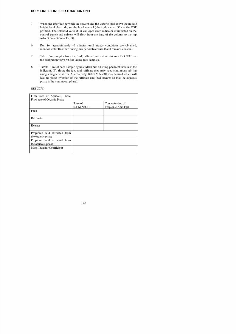
7. When the interface between the solvent and the water is just above the middle
height level electrode, set the level control (electrode switch S2) to the TOP
position. The solenoid valve (C3) will open (Red indicator illuminated on thecontrol panel) and solvent will flow from the base of the column to the top
solvent collection tank (L3).
6. Run for approximately 40 minutes until steady conditions are obtained,
monitor water flow rate during this period to ensure that it remains constant.
7. Take 15ml samples from the feed, raffinate and extract streams. DO NOT use
the calibration valve V8 for taking feed samples.
8. Titrate 10ml of each sample against M/10 NaOH using phenolphthalein as the
indicator. (To titrate the feed and raffinate they may need continuous stirring
using a magnetic stirrer. Alternatively: 0.025 M NaOH may be used which will
lead to phase inversion of the raffinate and feed streams so that the aqueous
phase is the continuous phase).
RESULTS:
Flow rate of Aqueous Phase
Flow rate of Organic Phase
Titre of
0.1 M NaOH
Concentration of
Propionic Acid kg/l
Feed
Raffinate
Extract
Propionic acid extracted from
the organic phase
Propionic acid extracted from
the aqueous phase
Mass Transfer Coefficient
UOP5 LIQUID/LIQUID EXTRACTION UNIT

8/10/2019 UOP5 Manual - Issue 18
http://slidepdf.com/reader/full/uop5-manual-issue-18 45/52
EXPERIMENT E
DEMONSTRATION OF SOLVENT RECOVERY
OBJECT OF EXPERIMENT:
To recover the solvent used in the liquid/liquid extraction experiments using the
distillation column.
EQUIPMENT SET-UP:
SUMMARY OF THEORY:
In the previous experiments, water has been used as the solvent to extract propionic
acid from the organic solvent. Solvent recovery can now be demonstrated using the
distillation column situated at the rear of the equipment on the left hand side.
The distillation column contains four sieve plates and is equipped with a reflux
UOP5 LIQUID/LIQUID EXTRACTION UNIT

8/10/2019 UOP5 Manual - Issue 18
http://slidepdf.com/reader/full/uop5-manual-issue-18 46/52
PROCEDURE:
On completion of an extraction experiment, organic solvent contaminated with
propionic acid will be contained in the solvent collecting tank. This batch can betransferred using the drain valve at the base of the tank (V7), into the distillation
column. Ensure that the level in the distillation column boiler is at least halfway up
the sight glass on the side of the boiler but do not overfill so that the level rises off the
gauge.
Make sure the regulator R1 is on the minimum setting i.e. fully anti-clockwise and
then press the red switch which will illuminate. Now turn the regulator clockwise to a
setting of say, 7. The cooling water supply to the condenser should now be turned on.
Take a sample of the contaminated organic solvent from the sample valve V10. As in
the experiment to determine the distribution coefficient, take a 10ml sample of this
using a pipette with a rubber bulb and titrate this against 0.1 M sodium hydroxide
solution using phenolphthalein as indicator. (Organic solvent 10ml sample will need
continuous stirring using a magnetic stirrer. Alternatively: 0.025 M NaOH may be
used which will lead to phase inversion of the raffinate and feed streams so that the
aqueous phase is the continuous phase).
When the liquid starts to boil, observe the foaming action on the distillation column
plates and adjust R1 so that a gentle action takes place. Adjust reflux valve C2 so that
not all of the liquid is allowed to fall into the purified solvent tank and some of the
condensed liquid is allowed to reflux back into the column.
At 15 minute intervals, take samples of the liquid in the distillation column boiler
(valve V10) and the purified organic tank from the flexible pipe on the reflux divider.
Do titrations on both samples. Continue to distil until the level of liquid in the boiler
gets low enough to operate the float switch which will turn off the power to the heater.
The purified organic can be transferred from the holding tank into the organic store
tank by using valve V5.
RESULTS:
Sample Titre of NaOH
boiler
Titre of NaOH
holding tank
Conc. acid
boiler
Conc. acid
holding tank
1
2
3
4
8/10/2019 UOP5 Manual - Issue 18
http://slidepdf.com/reader/full/uop5-manual-issue-18 47/52
GENERAL SAFETY RULES
1 Follow Relevant Instructions
a Before attempting to install, commission or operate equipment, all relevant
suppliers/manufacturers instructions and local regulations should be
understood and implemented.
b It is irresponsible and dangerous to misuse equipment or ignore instructions,
regulations or warnings.
c Do not exceed specified maximum operating conditions (e.g. temperature,
pressure, speed etc.)
2 Installation
a Use lifting tackle where possible to install heavy equipment. Where manual
lifting is necessary beware of strained backs and crushed toes. Get help from
an assistant if necessary. Wear safety shoes where appropriate.
b Extreme care should be exercised to avoid damage to the equipment during
handling and unpacking. When using slings to lift equipment ensure that the
slings are attached to structural framework and do not foul adjacent pipework,
glassware etc. When using fork lift trucks, position the forks beneath structural
framework ensuring that the forks do not foul adjacent pipework, glassware
etc. Damage may go unseen during commissioning creating a potential hazard
to subsequent operators.
c Where special foundations are required follow the instructions provided and
do not improvise. Locate heavy equipment at low level.
d Equipment involving inflammable or corrosive liquids should be sited in a
containment area or bund with a capacity 50% greater than the maximum
equipment contents.
e Ensure that all services are compatible with the equipment and that
independent isolators are always provided and labelled. Use reliable
connections in all instances, do not improvise.
f Ensure that all equipment is reliably earthed and connected to an electrical
supply at the correct voltage. The electrical supply must incorporate a Residual
Current Device (RCD) (alternatively called an Earth Leakage Circuit Breaker -
ELCB) to protect the operator from severe electric shock in the event of
misuse or accident.
g Potential hazards should always be the first consideration when deciding on a
suitable location for equipment. Leave sufficient space between equipment and
between walls and equipment.

8/10/2019 UOP5 Manual - Issue 18
http://slidepdf.com/reader/full/uop5-manual-issue-18 48/52
3 Commissioning
a Ensure that equipment is commissioned and checked by a competent memberof staff before permitting students to operate it.
4 Operation
a Ensure that students are fully aware of the potential hazards when operating
equipment.
b Students should be supervised by a competent member of staff at all times
when in the laboratory. No one should operate equipment alone. Do not leave
equipment running unattended.
c Do not allow students to derive their own experimental procedures unless they
are competent to do so.
d Serious injury can result from touching apparently stationary equipment when
using a stroboscope to `freeze´ rotary motion.
5 Maintenance
a Badly maintained equipment is a potential hazard. Ensure that a competent
member of staff is responsible for organising maintenance and repairs on a
planned basis.
b Do not permit faulty equipment to be operated. Ensure that repairs are carried
out competently and checked before students are permitted to operate the
equipment.
6 Using Electricity
a At least once each month, check that RCD's (ELCB's) are operating correctly
by pressing the TEST button. The circuit breaker must trip when the button is
pressed (failure to trip means that the operator is not protected and a repair
must be effected by a competent electrician before the equipment or electrical
supply is used).
b Electricity is the commonest cause of accidents in the laboratory. Ensure that
all members of staff and students respect it.
c Ensure that the electrical supply has been disconnected from the equipment
before attempting repairs or adjustments.
d Water and electricity are not compatible and can cause serious injury if they
come into contact. Never operate portable electric appliances adjacent to
equipment involving water unless some form of constraint or barrier is

8/10/2019 UOP5 Manual - Issue 18
http://slidepdf.com/reader/full/uop5-manual-issue-18 49/52
7 Avoiding fires or explosion
a Ensure that the laboratory is provided with adequate fire extinguishersappropriate to the potential hazards.
b Where inflammable liquids are used, smoking must be forbidden. Notices
should be displayed to enforce this.
c Beware since fine powders or dust can spontaneously ignite under certain
conditions. Empty vessels having contained inflammable liquids can contain
vapour and explode if ignited.
d Bulk quantities of inflammable liquids should be stored outside the laboratory
in accordance with local regulations.
e Storage tanks on equipment should not be overfilled. All spillages should be
immediately cleaned up, carefully disposing of any contaminated cloths etc.
Beware of slippery floors.
f When liquids giving off inflammable vapours are handled in the laboratory,
the area should be ventilated by an ex-proof extraction system. Vents on the
equipment should be connected to the extraction system.
g Students should not be allowed to prepare mixtures for analysis or other
purpose without competent supervision.
8 Handling poisons, corrosive or toxic materials
a Certain liquids essential to the operation of equipment, for example mercury,
are poisonous or can give off poisonous vapours. Wear appropriate protective
clothing when handling such substances. Clean up any spillage immediately
and ventilate areas thoroughly using extraction equipment. Beware of slippery
floors.
b Do not allow food to be brought into or consumed in the laboratory. Never use
chemical beakers as drinking vessels.
c Where poisonous vapours are involved, smoking must be forbidden. Notices
should be displayed to enforce this.
d Poisons and very toxic materials must be kept in a locked cupboard or store
and checked regularly. Use of such substances should be supervised.
e When diluting concentrated acids and alkalis, the acid or alkali should be
added slowly to water while stirring. The reverse should never be attempted.
9 Avoiding cuts and burns
a Take care when handling sharp edged components. Do not exert undue force
on glass or fragile items.

8/10/2019 UOP5 Manual - Issue 18
http://slidepdf.com/reader/full/uop5-manual-issue-18 50/52
10 Eye protection
a Goggles must be worn whenever there is a risk to the eyes. Risk may arisefrom powders, liquid splashes, vapours or splinters. Beware of debris from fast
moving air streams. Alkaline solutions are particularly dangerous to the eyes.
b Never look directly at a strong source of light such as a laser or Xenon arc
lamp. Ensure that equipment using such a source is positioned so that passers-
by cannot accidentally view the source or reflected ray.
c Facilities for eye irrigation should always be available.
11 Ear protection
a Ear protectors must be worn when operating noisy equipment.
12 Clothing
a Suitable clothing should be worn in the laboratory. Loose garments can cause
serious injury if caught in rotating machinery. Ties, rings on fingers etc. should
be removed in these situations.
b Additional protective clothing should be available for all members of staff and
students as appropriate.
13 Guards and safety devices
a Guards and safety devices are installed on equipment to protect the operator.
The equipment must not be operated with such devices removed.
b Safety valves, cut-outs or other safety devices will have been set to protect the
equipment. Interference with these devices may create a potential hazard.
c It is not possible to guard the operator against all contingencies. Use common
sense at all times when in the laboratory.
d Before starting a rotating machine, make sure staff are aware how to stop it in
an emergency.
e Ensure that speed control devices are always set at zero before starting
equipment.
14 First aid
a If an accident does occur in the laboratory it is essential that first aid
equipment is available and that the supervisor knows how to use it.
b A notice giving details of a proficient first-aider should be prominently
8/10/2019 UOP5 Manual - Issue 18
http://slidepdf.com/reader/full/uop5-manual-issue-18 51/52

8/10/2019 UOP5 Manual - Issue 18
http://slidepdf.com/reader/full/uop5-manual-issue-18 52/52