unusual precipitation of amorphous silicon nitride upon nitriding fe–2at.%si alloy
TRANSCRIPT

This article was downloaded by: [University of California Santa Cruz]On: 11 October 2014, At: 15:15Publisher: Taylor & FrancisInforma Ltd Registered in England and Wales Registered Number: 1072954 Registeredoffice: Mortimer House, 37-41 Mortimer Street, London W1T 3JH, UK
Philosophical MagazinePublication details, including instructions for authors andsubscription information:http://www.tandfonline.com/loi/tphm20
Unusual precipitation of amorphoussilicon nitride upon nitriding Fe–2at.%SialloySai Ramudu Meka a , Kyung Sub Jung a , Ewald Bischoff a & EricJan Mittemeijer a ba Max Planck Institute for Intelligent Systems (formerly Max PlanckInstitute for Metals Research), Heisenbergstrasse 3, D-70569 ,Stuttgart , Germanyb Institute for Materials Science, University of Stuttgart ,Stuttgart , GermanyPublished online: 02 Feb 2012.
To cite this article: Sai Ramudu Meka , Kyung Sub Jung , Ewald Bischoff & Eric Jan Mittemeijer(2012) Unusual precipitation of amorphous silicon nitride upon nitriding Fe–2at.%Si alloy,Philosophical Magazine, 92:11, 1435-1455, DOI: 10.1080/14786435.2011.648226
To link to this article: http://dx.doi.org/10.1080/14786435.2011.648226
PLEASE SCROLL DOWN FOR ARTICLE
Taylor & Francis makes every effort to ensure the accuracy of all the information (the“Content”) contained in the publications on our platform. However, Taylor & Francis,our agents, and our licensors make no representations or warranties whatsoever as tothe accuracy, completeness, or suitability for any purpose of the Content. Any opinionsand views expressed in this publication are the opinions and views of the authors,and are not the views of or endorsed by Taylor & Francis. The accuracy of the Contentshould not be relied upon and should be independently verified with primary sourcesof information. Taylor and Francis shall not be liable for any losses, actions, claims,proceedings, demands, costs, expenses, damages, and other liabilities whatsoever orhowsoever caused arising directly or indirectly in connection with, in relation to or arisingout of the use of the Content.
This article may be used for research, teaching, and private study purposes. Anysubstantial or systematic reproduction, redistribution, reselling, loan, sub-licensing,systematic supply, or distribution in any form to anyone is expressly forbidden. Terms &

Conditions of access and use can be found at http://www.tandfonline.com/page/terms-and-conditions
Dow
nloa
ded
by [
Uni
vers
ity o
f C
alif
orni
a Sa
nta
Cru
z] a
t 15:
15 1
1 O
ctob
er 2
014

Philosophical MagazineVol. 92, No. 11, 11 April 2012, 1435–1455
Unusual precipitation of amorphous silicon nitride upon nitriding
Fe–2at.%Si alloy
Sai Ramudu Mekaa*, Kyung Sub Junga, Ewald Bischoff a andEric Jan Mittemeijerab
aMax Planck Institute for Intelligent Systems (formerly Max Planck Institutefor Metals Research), Heisenbergstrasse 3, D-70569, Stuttgart, Germany;
bInstitute for Materials Science, University of Stuttgart, Stuttgart, Germany
(Received 22 August 2011; final version received 6 December 2011)
Silicon-nitride precipitation in ferritic Fe–2at.%Si alloy was investigatedupon nitriding in NH3/H2 gas mixtures, using light microscopy, hardnessmeasurements, scanning and transmission electron microscopy, X-raydiffraction and electron-probe microanalysis for microstructural charac-terisation. Surprisingly, ideally weak nitriding behaviour occurred uponnitriding thick (1mm) recrystallised Fe–2at.%Si alloy specimens. Thisphenomenon can be attributed to the onset of silicon-nitride precipitationonly after a certain degree of nitrogen supersaturation has been establishedat all depths in the specimen. Silicon-nitride precipitates formed inside theferrite grains and also along the ferrite grain boundaries. The precipitateswere amorphous and had a stoichiometry of Si3N4. The amorphous natureof the tiny precipitates has a thermodynamic origin. Nitride precipitationoccurred very slowly due to the very large volume misfit of the nitride withthe matrix. An anomalous non-monotonous hardness change occurredwith increasing nitriding time, which was ascribed to the initially fullyelastic accommodation of precipitate/matrix misfit. The nitrogen uptakerate increased upon continued nitriding as a result of ‘‘self-catalysis’’. Thepossible, favourable application of amorphous silicon-nitride precipitatesas grain-growth inhibitors in the production of grain-oriented electricalsteel is discussed.
Keywords: nitriding; Fe–Si alloy; precipitation kinetics; amorphous siliconnitride; electrical steel
1. Introduction
Nitriding is a widely employed thermochemical surface treatment to enhance themechanical (fatigue and wear) and chemical (corrosion) properties of ferritic steelcomponents [1–5]. The presence of alloying elements, with chemical affinity fornitrogen, induces complex nitriding behaviour. Therefore, nitriding studies onsimple, iron-based binary alloys, such as Fe–Al [6–8], Fe–Cr [9,10] and Fe–V [11,12],or, mostly recently, some ternary alloys, such as Fe–Cr–C [13] and Fe–Cr–Al [14,15],have been carried out, in particular, to investigate how a substitutionally dissolved
*Corresponding author. Email: [email protected]
ISSN 1478–6435 print/ISSN 1478–6443 online
� 2012 Taylor & Francis
http://dx.doi.org/10.1080/14786435.2011.648226
http://www.tandfonline.com
Dow
nloa
ded
by [
Uni
vers
ity o
f C
alif
orni
a Sa
nta
Cru
z] a
t 15:
15 1
1 O
ctob
er 2
014

alloying element with affinity for nitrogen reacts with interstitially dissolved nitrogenin the ferrite matrix [16].
Presently, Si is not deliberately added to steel to enhance the properties of steelupon nitriding. However, steels usually contain Si as it is one of the principal de-oxidisers for steel melts and also Si is an important alloying element in TRIP, bainiticand electrical steels [17,18]. Hence, it is important to understand fundamentally thenucleation and growth of silicon nitride upon nitriding ferritic steels.
A significant thermodynamic, chemical driving force exists for the precipitationof silicon nitride upon nitriding. Thus, silicon should be considered a strong nitrideformer and (ideally) strong nitriding kinetics are expected (for a discussion on strong,moderate and weak Me–N interaction/kinetics (Me¼dissolved alloying element) ina ferrite matrix, see [19]). Little is known about the precipitation of silicon nitrideupon nitriding Fe–Si alloys. The work performed to date is of a fragmentary nature[20–22] and, moreover, the results reported are not in total agreement. For example,in [20], the development of only crystalline silicon nitride precipitates was reported,whereas in much later work [22] it was demonstrated that the developed silicon-nitride precipitates are amorphous and of the composition Si3N4. It was shown in[21] that the precipitation of silicon nitride occurs much faster in a deformed ferritematrix than in a recrystallised ferrite matrix.
The present study combines microstructural analysis with a description of theprecipitation kinetics for the gaseous nitriding of an Fe–2at.%Si alloy. Strikinglyunusual phenomena for the nitriding of a binary Fe–Me alloy have been observedand discussed. As a result, a first, comprehensive picture has been obtained for thenitriding behaviour of an iron-based Fe–Si alloy. Preliminary results obtained in thisproject have been presented in a short conference paper [23].
2. Experimental details
2.1. Specimen preparation
An Fe–2at.%Si alloy cast rod, of dimensions of 10mm in diameter and 100mm inlength, was produced by induction melting of elemental granules of iron (purity:99.98 wt.%) and pieces of silicon (purity: 99.999 wt.%) under a protective argonatmosphere. The amounts of silicon and light element impurities in the produced castwere analysed. The silicon content was determined by inductively coupled plasma-optical emission spectroscopy (ICP-OES). Nitrogen and oxygen contents weremeasured by applying carrier hot gas extraction, while sulphur and carbon contentswere determined by the combustion method. The results of this chemical analysis areshown in Table 1.
Table 1. Levels of silicon and light element impurities in the cast Fe–2at.%Si alloy.
Si
N (mg/g) O (mg/g) S (mg/g) C (mg/g)wt.% at.%
1.03� 0.02 2.03� 0.04 < 5 67� 10 <10 20� 2
1436 S.R. Meka et al.
Dow
nloa
ded
by [
Uni
vers
ity o
f C
alif
orni
a Sa
nta
Cru
z] a
t 15:
15 1
1 O
ctob
er 2
014

The cast rod was cold-rolled to produce sheets having a thickness of approx-imately 1mm. From these sheets, rectangular specimens with lateral dimensions10� 15mm were cut and the surface of the specimens was ground and polished (finalstage with 1-mm diamond paste). The prepared specimens were placed into a quartztube which was evacuated, filled with argon gas and encapsulated, and subsequentlyannealed at 750�C for 2 h to recrystallise the specimens. Thereafter, the specimenswere ultrasonically cleaned in ethanol and subjected to the nitriding treatment.
2.2. Nitriding and denitriding
The specimens were nitrided in a laboratory-scale, vertical quartz tube furnace havingan inner diameter of 28mm, equipped with a facility to suspend the specimen in themiddle of the furnace with the help of a quartz fibre. The furnace temperature wascontrolled within a 1�C variation. For the nitriding treatment, high purity ammonia(99.99 vol.%) and hydrogen (99.999 vol.%) gases were used. After setting the requiredflow-rates of ammonia gas (45 ml/min) and hydrogen gas (455 ml/min), the specimenwas suspended in the uniform temperature zone of the furnace (580�C). The total gasflow-rate of 500 ml/min corresponds with a linear gas velocity of 13.5mm/s at roomtemperature for the quartz tube furnace used. At this linear gas velocity, a change inthe chemical composition of the gas mixture due to the dissociation of ammonia canbe neglected. These nitriding conditions result in a nitriding potential (rN) of0.104 atm�1/2 [24]. At the applied temperature (580�C) and rN (0.104 atm�1/2), no ironnitrides can develop upon nitriding pure iron, according to the Lehrer diagram [25].After completing the nitriding treatment, the specimens were quenched in a water-filled quenching flask. Denitriding of the nitrided specimens was performed ina similar way as nitriding but at a temperature of 450�C in flowing hydrogen gas(500 ml/min). Under these denitriding conditions, silicon nitride is stable, whereasnitrogen, interstitially dissolved in the ferrite, is removed from the specimen.
2.3. Microstructural characterisation
2.3.1. Light microscopy and scanning electron microscopy
For investigating the microstructure, the nitrided specimens were cut perpendicularto the nitrided surface and hot embedded in Struers PolyFast. Before embedding, allspecimens were stored at room temperature for about 3 days. During embedding, thespecimen together with the embedding material (Polyfast) was heated for 5 min at180�C followed by cooling to room temperature at a cooling rate of about 50�C/min.During the preceding storage at room temperature and during this subsequent heattreatment, precipitation of �00-Fe16N2 can occur in the nitrogen-supersaturatedferrite which leads to a microstrain and hardness increase [26,27]. This hardnessincrease is taken into account in the discussion given in Section 7. The embeddedspecimens were prepared for metallographic examination by grinding and polishing(finishing with 1-mm diamond paste) followed by etching with 2 vol.% Nital. Lightmicroscopy investigations were performed using a Zeiss Axiophot microscopeequipped with a digital camera (Olympus Color View IIIu). Scanning electronmicroscopy (SEM) investigations were carried out using a Jeol JSM-6300F
Philosophical Magazine 1437
Dow
nloa
ded
by [
Uni
vers
ity o
f C
alif
orni
a Sa
nta
Cru
z] a
t 15:
15 1
1 O
ctob
er 2
014

microscope equipped with a field emission gun and employing an acceleratingvoltage of 3 kV and a working distance of 15mm.
2.3.2. Transmission electron microscopy (TEM)
To characterise the fine nitride precipitates developing upon nitriding, electrontransparent TEM foils were prepared. Discs of 3mm diameter were stamped with amechanical punch from sheets produced by removing material mechanically fromboth sides (faces) of the nitrided specimen such that the depth range of 125–140 mmbelow the specimen surface became available for investigation (i.e. subsequent foilpreparation). These discs were subjected to polishing and dimpling operationsfollowed by final thinning employing Ar ion milling (Gatan PIPS-691). For ionmilling, an accelerating voltage of 3–4 kV, a current of 10–12 mA, a milling time of4–10 h and an angle of ion incidence of 8� were used and the specimen stage wascooled by liquid nitrogen.
Some of the TEM specimens were prepared by the jet electropolishing techniqueusing a Struers Tenupol–3 apparatus, employing a bath composition of 85 vol.%acetic acid and 15 vol.% perchloric acid, a current of 22–29mA, a voltage of 20.5 V,a temperature of 279–280K, a flow-rate setting of ‘‘20’’ and a treatment time of225–388 s, followed by rinsing in, consecutively, ethanol, acetone and isopropanol.
TEM investigations were performed using a Philips CM 200 microscopeoperating at 200 kV, equipped with an energy-dispersive X-ray detection system(EDX). The bright-field (BF), dark-field (DF) images and the selected areadiffraction patterns (SADPs) were recorded using a Gatan CCD camera attachedto the microscope. Qualitative compositional analysis of the nitride precipitates,which developed upon nitriding, was carried out by energy-dispersive X-ray analysis(EDX) using a detector attached to the TEM.
2.3.3. Quantitative analysis of composition and nitrogen uptake; electron probemicroanalysis (EPMA) and weight measurements
For the determination of elemental (Fe, Si and N) concentrations in the nitridedzone, EPMA was performed on the polished cross-sections of the nitrided specimensemploying a Cameca SX100 microprobe. Measurements were performed using anaccelerating voltage of 15 kV and a current of 100 nA. To obtain the content of Fe,Si and N at each measured point, the intensities of the characteristic Fe-K�, Si-K�and N-K� radiations were measured and divided by the corresponding intensitiesmeasured from standard specimens (pure iron, pure silicon and � 0 iron nitride (fornitrogen)). The elemental concentrations were calculated from these intensity ratiosapplying the �(�z) approach [28].
To accurately obtain the small amounts of nitrogen in both the nitrided anddenitrided specimens, samples were weighed using a Mettler’s microbalance beforeand after the nitriding and denitriding treatments. From the weight gain/loss of thenitrided/denitrided samples, the amount of nitrogen taken up/lost was determined.
2.3.4. X-ray diffraction (XRD)
X-ray diffractograms were recorded using a PANalytical X’pert Multipurposediffractometer equipped with a graphite monochromator in the diffracted beam,
1438 S.R. Meka et al.
Dow
nloa
ded
by [
Uni
vers
ity o
f C
alif
orni
a Sa
nta
Cru
z] a
t 15:
15 1
1 O
ctob
er 2
014

employing Co-K� radiation and Bragg-Brentano geometry. During the measure-ments, the specimens were rotated around their surface normal to get bettercrystallite statistics.
2.3.5. Microhardness measurement
Microhardness measurements were carried out on the cross-sections of nitridedspecimens by use of a Vickers microhardness tester (Leica VMHT Mot). A load of50 g, an indentation speed of 50 mm/s and a loading time of 10 s were applied. Eachhardness value presented is the average of four hardness measurements; the standarddeviation of the four measurements is used as an error estimate.
3. Morphology; light optical and scanning electron microscopy
Light optical micrographs recorded from the etched cross-sections of an unnitridedrecrystallised Fe–2at.%Si alloy specimen and of the recrystallised Fe–2at.%Si alloyspecimens nitrided for different times (30, 65, 165 and 332 h) at 580�C using a rN of0.104 atm�1/2 are shown in Figure 1. Surprisingly, the micrographs recorded from thespecimens nitrided for different times show no distinction of a surface adjacentnitrided layer and an unnitrided core region, in contrast with results obtained fornitrided Fe–Al [7], Fe–Cr [9], Fe–V [11] and Fe–Ti [29] alloys. Instead, the etchingcontrast was found to be uniform at all depths of the 1-mm thick specimens, butchanging with nitriding time, indicative of progress in the nitriding reaction(similarly at all depths) with nitriding time (Figure 1b-e). This finding suggests theoccurrence of ideally weak nitriding kinetics (implying a constant nitrogenconcentration and hardness, as function of depth, for different nitriding times; seeFigure 1 in [19]), which is confirmed by the measured hardness- and nitrogenconcentration-depth profiles (see Section 5).
The observation of ideally weak nitriding behaviour for a specimen of such largethickness, 1mm, is highly unusual. For example, nitriding of recrystallised Fe–Alalloy also shows weak nitriding interaction but, to realise ideally weak nitridingbehaviour (i.e. the nitrogen concentration is constant at all depths) undercomparable conditions, the specimen should be 0.1mm thick or less, i.e. 10 timesless thick [19] (see Section 5).
SEMperformed at cross-sections of the specimens nitrided for different times showa thin layer of nitride phase precipitated along the ferrite-grain boundaries of the 30-hnitrided specimen (Figure 2a). Upon prolonged nitriding fine, more or less cubical androd/plate-like precipitates develop inside the ferrite grains (Figure 2b,c). Adjacent tothe grain-boundary nitride layer, a thin precipitate-free zone (PFZ) occurs (Figure 2d).TEM investigation showed that the precipitates both inside the ferrite grains and alongthe ferrite grain boundaries are amorphous silicon nitride (see Section 4).
The very slow nucleation and growth of (amorphous) silicon nitride can beunderstood in view of the extraordinarily large volume misfit between nitrideparticles and matrix: 105% for Si3N4,
1 compared to 52% for CrN, 50% for VN or64% for TiN. This also explains why precipitation of silicon nitride occurs morerapidly, i.e. more easily, at grain boundaries, where the misfit can be accommodatedmore easily, apart from a higher driving force for nucleation due to the annihilationof grain-boundary area.
Philosophical Magazine 1439
Dow
nloa
ded
by [
Uni
vers
ity o
f C
alif
orni
a Sa
nta
Cru
z] a
t 15:
15 1
1 O
ctob
er 2
014

4. Amorphous nature of the silicon-nitride precipitates: transmission electron
microscopy (TEMþEDX) and X-ray diffraction (XRD)
No diffraction spots, additional to those belonging to ferrite, were detected in anySADPs recorded from TEM foils prepared from nitrided Fe–2at.%Si alloyspecimens. A diffuse intensity (‘‘halo’’) around the transmitted beam is observed
Figure 1. Light optical micrographs recorded from cross-sections of Fe–2at.%Si alloyspecimens: (a) unnitrided, (b) 30 h nitrided, (c) 65 h nitrided, (d) 165 h nitrided, and (e) 332 hnitrided (T¼ 580�C; rN¼ 0.104 atm�1/2). A uniform etching contrast is observed for thenitrided specimens: distinction between a nitrided zone and an unnitrided core region cannotbe made. The etching contrast becomes more pronounced with increasing nitriding time.
1440 S.R. Meka et al.
Dow
nloa
ded
by [
Uni
vers
ity o
f C
alif
orni
a Sa
nta
Cru
z] a
t 15:
15 1
1 O
ctob
er 2
014

(see inset to Figure 3a), indicating the possible presence of an amorphous (silicon-nitride) phase, as reported for the first time in an earlier, unnoticed work [22]. ATEM dark-field (DF) image formed from part of the diffuse intensity around thetransmitted beam (see the encircled region in the SADP shown as an inset in Figure3a) reveals the (precipitate) regions contributing to the diffuse intensity, whichappear brighter (Figure 3a). These observations demonstrate the amorphous natureof the nitride precipitates. The same type of TEM analysis was applied to the grain-boundary precipitates (not reported in the earlier work [22]), which showed that thegrain-boundary precipitates are also amorphous (Figure 3b).
The amorphous nitride particles in the bulk appear to have a cubical- or plate(rod)-like morphology (see Figures 3a and 5a,c). In an early note [30] on nitridediron-silicon alloy, particles of the same cubical morphology, as found here and in [22]were observed, but they could not be identified.
Employing the electropolishing technique for TEM foil preparation (Section2.3.2) resulted in selective dissolution of the less inert ferrite matrix, leaving therather inert silicon-nitride precipitates. As a result, the nitride precipitates becameseparated from the ferrite matrix and some precipitates appeared ‘‘self-supporting’’near the (jet-polished) holes in the TEM foil (Figure 3c). The electron-diffractionpattern of these particles (inset to Figure 3c) only shows the diffuse intensity rings, asdiscussed above. Application of local X-ray elemental point analysis (EDX) showed
Figure 2. SEM micrographs recorded from cross-sections of nitrided (T¼ 580�C;rN¼ 0.104 atm�1/2) Fe–2at.%Si alloy specimens. After 30 h (a) of nitriding, bands of nitridephase have developed along the ferrite-grain boundaries. With increasing nitriding time to 165h (b) and 332 h (c), fine precipitates have developed inside the ferrite grains. Precipitate-freeregions occur adjacent to the ferrite-grain boundaries (d) (332 h).
Philosophical Magazine 1441
Dow
nloa
ded
by [
Uni
vers
ity o
f C
alif
orni
a Sa
nta
Cru
z] a
t 15:
15 1
1 O
ctob
er 2
014

that the precipitates contain both silicon and nitrogen. The amount of nitrogen takenup by a totally nitrided specimen (Section 6) indicates that silicon precipitates as thestoichiometric silicon nitride, Si3N4.
X-ray diffractograms recorded from the surface of the nitrided specimens showedonly broadened diffraction peaks of the ferrite matrix (Figure 4): compatible with theamorphous nature of the silicon-nitride precipitates (see above), no reflectionscorresponding to silicon nitride occur. The broadening of the diffraction peaks of the
Figure 3. (a) TEM-DF image and the corresponding SADP (electron-beam/zone axis not farfrom [113]�-Fe) recorded from the ion-thinned TEM foil of a 332-h nitrided Fe–2at.%Sispecimen. DF image was formed with the diffuse intensity from the halo around thetransmitted beam (as contained by the white circle indicated in the SADP in (a); the diffractionspots encompassed by black circles pertain to 113-type reflections of iron oxide, Fe3O4, whichdevelops on the surface of the TEM foil). The bright, contrastless regions are amorphoussilicon nitride (see text). (b) TEM-DF image (formed in a similar way as the DF image (a))recorded from the ion-thinned TEM foil prepared from a 332-h nitrided Fe–2at.%Si specimen.The bright, contrastless appearance of the grain-boundary phase is compatible with itsamorphous nature. (c) TEM BF image and the corresponding SADP recorded from the TEMfoil prepared by electro-jet polishing from a 130-h nitrided Fe–2at.%Si specimen. SADP fromsuch isolated particles (c) shows only diffuse intensity rings compatible with an amorphousnature of the nitride particles. The isolated amorphous silicon-nitride nanoprecipitates have athickness up to 50 nm and length up to 1000 nm. The precipitates became isolated from thematrix due to selective dissolution of the ferrite matrix.
1442 S.R. Meka et al.
Dow
nloa
ded
by [
Uni
vers
ity o
f C
alif
orni
a Sa
nta
Cru
z] a
t 15:
15 1
1 O
ctob
er 2
014

ferrite matrix is ascribed to the microstrain (see [31]), induced by the large volumemisfit (105%) between silicon-nitride precipitates and the surrounding ferrite matrix.
The very slow nucleation and growth of silicon nitride in the ferrite matrix (seeresults presented in Section 5) leaves more than enough time for Si and N atoms tocome together by solid-state diffusion in the ferrite matrix and to arrange themselvesin the crystalline modification of Si3N4. The emergence of an amorphous modifi-cation then should have a thermodynamic rather than a kinetic origin. For smallersized precipitates (having a relatively large interface/volume ratio), the relatively lowenergy of the interface between amorphous silicon nitride and the crystalline ferritematrix, compared to the energy of the interface between crystalline silicon nitride andthe crystalline ferrite matrix, can thermodynamically stabilise the amorphous natureof the silicon-nitride precipitates, as first suggested in [22] by adopting a theoreticalframework reviewed in [32]. Remarkably, the faces of the cubical particles areparallel to {100}�-Fe (see Figure 5a,c and Figure 2 in [22]), suggesting that theamorphous Si3N4/crystalline �-Fe interface preferably forms along {001}�-Fe.
Efforts in the present work to crystallise the amorphous precipitates by annealingthe specimens at 700�C in a nitriding atmosphere (NH3/H2 mixture at a rN of0.02 atm�1/2) for 40 h were unsuccessful. This is compatible with the very hightemperatures (�1200�C) needed to crystallise bulk specimens of amorphous siliconnitride [33]. Such a high crystallisation temperature has been attributed to the verylow diffusivities of Si and N in the strongly covalently bonded silicon nitride [34]. It isnoted here that, similar to the internal precipitation of silicon nitride, precipitation ofspherical amorphous silica (SiO2) has been observed during internal oxidation ofCu–Si [35] and Ni–Si [36] alloys, which here is suggested to have the samethermodynamic origin as the precipitation of amorphous Si3N4 particles upon
Figure 4. Superposition of X-ray diffractograms (Co-K� radiation) recorded from the surfaceof an unnitrided Fe–2at.%Si specimen and a 332-h nitrided (T¼ 580�C; rN¼ 0.104 atm�1/2)Fe–2at.%Si alloy specimen. Only reflections of the ferrite matrix can be detected. The ferritereflections become broadened upon nitriding due to the microstrain in the ferrite matrixsurrounding the misfitting silicon-nitride precipitates.
Philosophical Magazine 1443
Dow
nloa
ded
by [
Uni
vers
ity o
f C
alif
orni
a Sa
nta
Cru
z] a
t 15:
15 1
1 O
ctob
er 2
014

nitriding Fe–Si alloys (no explanation was given in [35] and [36] for the developmentof amorphous SiO2 particles in a crystalline matrix).
The employed nitriding temperature (580�C) in this work is significantly lowerthan the (high) temperature (�1200�C) needed for the crystallisation of amorphoussilicon nitride (see above). This suggests that, even upon growth of amorphoussilicon-nitride precipitates at 580�C to a size beyond that where crystallinemodification would be stable (cf. Section 5 in [32]), the amorphous nature couldbe preserved due to the difficult kinetics of crystallisation.
Figure 5. TEM-BF image (a) and the corresponding SADP ((b) electron-beam/zone axis nearto [001]�-Fe) recorded from the Fe–2at.%Si alloy specimen nitrided for 332 h and the DFimage (c) formed with the -103 diffraction spot (shown with white circle in the SADP in (b)) of�00-Fe16N2. The direction perpendicular to the (100) lattice planes of �-Fe and the diffractionvector, g, have been indicated in (c). In addition to cubical-shaped amorphous silicon-nitrideprecipitates (indicated with white dashed ovals in (a) and (c)), crystalline �0 0-Fe16N2 platelets(indicated with small black arrows in (a) and (c)) can be observed. The calculated diffractionpattern for the orientation relationship between ferrite and �00-nitride, (010)�//(001)�0 0 and[001]�//[010]�0 0, is shown in (d). In (d), Miller indices for �00 spots are underlined. The locationof the 103-type diffraction spots of �0 0, relative to that of the matrix diffraction spots, and theappearance of the split 200-type diffraction spot of the �-Fe matrix (shown with white arrowin (b)) are compatible with the orientation relationship between �00 and ferrite (b and d).
1444 S.R. Meka et al.
Dow
nloa
ded
by [
Uni
vers
ity o
f C
alif
orni
a Sa
nta
Cru
z] a
t 15:
15 1
1 O
ctob
er 2
014

TEM investigation on a ferrite grain in the TEM foil with an electron-beam/zoneaxis close to [001]�-Fe showed, in addition to amorphous silicon-nitride precipitates,the presence of crystalline �00-Fe16N2 precipitates along {100} planes of the ferritematrix, having a platelet-type morphology (see bright-field, dark-field and SADPshown in Figure 5). Due to the orientation relationship between �00-nitride and ferrite[37,38], (010)�//(001)�0 0 and [001]�//[010]�0 0, and its variants, the strongest reflectionsof �00 overlap with/are close to ferrite reflections (Figure 5d). This, together with thevery low intensity of �00 nitride diffraction spots (in particular the ‘‘superstructure’’reflections), shows that only a few �00 diffraction spots can be easily detected asseparate reflections: e.g. 103-type spots and 004-type spots close to 002-type spots ofthe ferrite matrix (see SADP shown in Figure 5b and compare with the calculateddiffraction pattern in Figure 5d). The occurrence of these �00-nitride precipitates islikely due to precipitation from the nitrogen-supersaturated ferrite matrix duringcooling (water quenching) and/or upon subsequent room temperature aging [26,27]of the nitrided specimen. This could, in particular, occur for the 332-h nitridedspecimen shown in Figure 5, as the nitrogen solubility of the matrix of long-timenitrided specimens is relatively large (see Section 6).
5. Ideally weak nitriding kinetics: hardness- and nitrogen
concentration-depth profiles
Vickers hardness-depth profiles, measured on cross-sections of the Fe–2at.%Si alloyspecimens nitrided for different times at 580�C by applying a rN of 0.104 atm�1/2, areshown in Figure 6. At all times, the hardness increase due to nitriding is the same atall depths in the nitrided specimens.
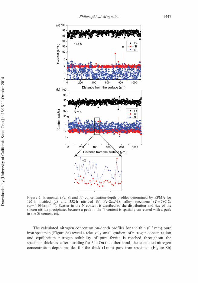
The measured (EPMA) elemental concentration-depth profiles show that thenitrogen content is the same at all depths in the nitrided specimens (Figure 7), whichis compatible with the hardness-depth profiles. The scatter in the measured N and Sicontent is ascribed to the distribution and size of the silicon-nitride precipitates in thebulk of the grains and at the grain boundaries. Indeed, the variation in N content iscorrelated with the variation in Si content (Figure 7c). The higher sensitivity of theEPMA measurements for Si than for the light element N led to a larger scatter in themeasured N-content values than in the measured Si-content values.
The observed uniform, depth-independent nature of the hardness, nitrogencontent and etching contrast (cf. Section 3) of the nitrided specimens is a clearmanifestation of ideally weak nitriding kinetics (see Figure 3b in [19]). Such ideallyweak nitriding kinetics imply that the silicon-nitride precipitation reaction initiates atthe same time at all depths and proceeds at the same rate at all depths, i.e. theamount of silicon nitride formed by precipitation is the same at all depths of thenitrided specimens.
The occurrence of ideally weak nitriding kinetics implies that the apparentincubation time for alloying element nitride (MeNn) nucleation is (much) larger thanthe time required to homogeneously saturate the entire specimen with nitrogen.In other words, the alloying element nitride precipitation initiates at the same time atall depths of the nitrided specimen. Thereafter, in accordance with the occurrence ofideally weak nitriding kinetics throughout the precipitation reaction, inwardly
Philosophical Magazine 1445
Dow
nloa
ded
by [
Uni
vers
ity o
f C
alif
orni
a Sa
nta
Cru
z] a
t 15:
15 1
1 O
ctob
er 2
014

diffusing nitrogen prefers to (again) saturate the ferrite matrix throughout thespecimen with dissolved nitrogen, rather than to react near the surface with silicon toform new or allow the growth of existing silicon-nitride precipitates.
The nitrogen concentration-depth profiles, which develop upon nitriding of pureiron, can be easily calculated numerically, recognising the competition between thefinite rates of surface reactions, such as ammonia dissociation, nitrogen diffusioninto the solid substrate and the association of surface-adsorbed nitrogen atoms andtheir subsequent desorption as N2 molecules. Due to the finite rates of thesecompeting surface reactions, the nitrogen-surface concentration increases withnitriding time up to the establishment of a stationary state or local (¼at the surface)thermodynamic equilibrium [39–41]. To achieve local thermodynamic equilibrium(instead of a stationary state), the desorption rate of nitrogen gas from the surface bythe association of the surface-adsorbed nitrogen atoms must be neglectable [39–41].2
For details on the numerical calculation method followed in this work, see theAppendix in [39]. Calculations were performed for the specimen thickness and thenitriding conditions employed in the present work (1mm thick Fe–2at.%Si alloyspecimens nitrided at 580�C using a rN of 0.104 atm�1/2) and in earlier work (0.3mmthick Fe–1.75at.%Si alloy specimens nitrided at 575�C using a rN of 0.075 atm�1/2
[21]). For calculations, the following data were used. The equilibrium nitrogensolubility of ferrite at 580�C for a rN of 0.104 atm�1/2 is 0.27at.% and at 575�C for arN of 0.075 atm�1/2 is 0.19at.% (using data from [41]). The diffusion coefficients ofnitrogen in pure ferrite at 580�C and at 575�C are 1.122� 10�7 cm2/s and1.052� 10�7 cm2/s, respectively (using data from [42]). The ammonia-dissociationreaction-rate coefficient on the iron surface at 580�C for a rN of 0.104 atm�1/2 is9.58� 10�6 cm/s and at 575�C for a rN of 0.075 atm�1/2 is 9.31� 10�6 cm/s (usingdata from [43,44]). The results of such calculations for nitrided ferrite specimens, forthe thicknesses, nitriding potentials and temperatures indicated above, are presentedin Figure 8 (note the different scales used for the abscissas in this figure).
Figure 6. Hardness (load¼ 50 g, time¼ 10 s)-depth profiles measured on cross-sections ofunnitrided and nitrided (T¼ 580�C; rN¼ 0.104 atm�1/2) for different times (as indicated in thefigure) Fe–2at.%Si alloy specimens.
1446 S.R. Meka et al.
Dow
nloa
ded
by [
Uni
vers
ity o
f C
alif
orni
a Sa
nta
Cru
z] a
t 15:
15 1
1 O
ctob
er 2
014
The calculated nitrogen concentration-depth profiles for the thin (0.3mm) pure
iron specimen (Figure 8a) reveal a relatively small gradient of nitrogen concentration
and equilibrium nitrogen solubility of pure ferrite is reached throughout the
specimen thickness after nitriding for 5 h. On the other hand, the calculated nitrogen
concentration-depth profiles for the thick (1mm) pure iron specimen (Figure 8b)
Figure 7. Elemental (Fe, Si and N) concentration-depth profiles determined by EPMA for165-h nitrided (a) and 332-h nitrided (b) Fe–2at.%Si alloy specimens (T¼ 580�C;rN¼ 0.104 atm�1/2). Scatter in the N content is ascribed to the distribution and size of thesilicon-nitride precipitates because a peak in the N content is spatially correlated with a peakin the Si content (c).
Philosophical Magazine 1447
Dow
nloa
ded
by [
Uni
vers
ity o
f C
alif
orni
a Sa
nta
Cru
z] a
t 15:
15 1
1 O
ctob
er 2
014

show the occurrence of relatively large gradients of nitrogen concentration andequilibrium nitrogen solubility is reached throughout the specimen thickness onlyafter a long nitriding time of 20 h (Figure 8a and b).
For a thin (0.3mm) recrystallised Fe–1.75at.%Si alloy specimens nitrided at575�C an incubation time of 10 h was observed for silicon-nitride precipitation [21],which is significantly larger than the time needed for nitrogen saturation of thespecimen (which is about 5 h; see Figure 8a). Hence, the occurrence of ideally weaknitriding kinetics is expected and was actually observed.
In view of the incubation time of 10 h for initiating silicon-nitride precipitationin a Fe–1.75at.%Si alloy specimen nitrided at 575�C, and the need of a nitridingtime of at least 20 h for nitrogen saturation of a specimen of thickness 1mm at 580�C(see above), the occurrence of ideally weak nitriding interaction for the thick (1mm)Fe–2at.%Si alloy specimens nitrided at 580�C is, at first sight, surprising. Thisfinding can be discussed as follows.
Figure 8. Calculated (see text) nitrogen concentration-depth profiles developing with nitridingpure iron specimens of different thickness (note the different scales of the abscissas). (a) A 0.3-mm thick specimen: nitrided at 575�C employing a rN of 0.075 atm�1/2. (b) A 1-mm thickspecimen: nitrided at 580�C employing a rN of 0.104 atm�1/2.
1448 S.R. Meka et al.
Dow
nloa
ded
by [
Uni
vers
ity o
f C
alif
orni
a Sa
nta
Cru
z] a
t 15:
15 1
1 O
ctob
er 2
014

The incubation time for silicon-nitride precipitation in the thick (1mm) Fe–2at.%Si specimen nitrided at 580�C is about 30 h (see Section 7), which is three timeslonger than reported [21] for the thin (0.3mm) Fe–1.75at.%Si specimens at asomewhat lower temperature (575 versus 580�C) and at a somewhat smaller siliconcontent (1.75 versus 2.03at.%). In view of the calculated nitrogen concentration-depth profiles (Figure 8a and b), it may be concluded that the apparent incubationtime for silicon-nitride precipitation is always longer than the time necessary fornitrogen saturation of the matrix throughout the thickness of the specimen. In otherwords, silicon nitride can only start to precipitate after the equilibrium nitrogensolubility of the ferrite matrix has been realised throughout the specimen. Then,maintaining (throughout the entire precipitation reaction) the ferrite matrix in theentire specimen saturated with dissolved nitrogen, ideally weak nitriding kinetics [19]occur. An extreme consequence of this reasoning is that weak nitriding kinetics areexpected for Fe–2at.%Si alloy at 580�C for specimens of any thickness. Alternatively,for an infinitely thick specimen, the incubation time would be infinitely long: thenitrogen entering the specimen from the gas phase prefers to maintain its dissolvedstate in the ferrite matrix and, only after a certain degree of nitrogen supersaturationof the ferrite matrix has been attained at all depths (i.e. has been forced to occur byemploying a specimen of finite thickness), does silicon-nitride precipitation set in.
6. Nitrogen solubility of the ferrite matrix and composition of the amorphous
nitride precipitates
The amounts of strongly bonded nitrogen (to silicon in the form of silicon-nitrideprecipitates) and of weakly or less strongly bonded nitrogen (interstitially dissolvednitrogen and nitrogen possibly adsorbed at the silicon-nitride/ferrite-matrix interface[45]), in specimens nitrided for different times, were obtained by hydrogen reduction/denitriding at 450�C. Whereas silicon nitride is stable against hydrogen reduction at450�C, the weakly bonded, interstitially dissolved and possibly interface-adsorbednitrogen atoms are removed from the specimen upon denitriding. From themeasured mass changes (see Section 2.3.3), the amounts of nitrogen present in thenitrided and denitrided specimens were determined and the results are presented inTable 2 (note that the distribution of nitrogen is uniform in the nitrided specimens;see Figures 1, 6 and, in particular, Figure 7).
The amount of nitrogen remaining in the specimen after denitriding increaseswith increasing nitriding time (see third column in Table 2). The amount of nitrogenremoved from the specimen during denitriding also increases with increasingnitriding time (see column 4 in Table 2).3 Both observations suggest that, withincreasing nitriding time, dissolved Si gradually precipitates as silicon nitride. As aconsequence, the nitrogen solubility of the ferrite matrix increases (dissolvedSi decreases the nitrogen solubility of ferrite [46,47]; see column 4 in Table 2 andfootnote 3). After complete precipitation of Si as silicon nitride (after 825 h ofnitriding, the saturation, plateau level of nitrogen uptake is reached; Figure 9), theamount of nitrogen removed during the denitriding treatment is slightly larger thanthe equilibrium N solubility of pure ferrite. Nitrogen in excess of the equilibriumsolubility is called ‘‘excess nitrogen’’ (for more information on excess N, see [45]).
Philosophical Magazine 1449
Dow
nloa
ded
by [
Uni
vers
ity o
f C
alif
orni
a Sa
nta
Cru
z] a
t 15:
15 1
1 O
ctob
er 2
014

The nitrogen content remaining in the 825-h nitrided specimen after denitriding(2.65at.%) is nearly equal to the nitrogen content expected if all Si present in the Fe–2.03at.%Si alloy would precipitate as silicon nitride of composition Si3N4 (2.64at.%).Hence, the amorphous silicon-nitride precipitates have the composition Si3N4.
7. Initial stage of nitride precipitation and ‘‘self-catalysis’’: non-monotonous
hardness change and increasing nitrogen-uptake rate with nitriding time
An unusual, non-monotonous change in hardness of the nitrided specimens withincreasing nitriding time was observed (Figure 9; see also Figure 6). After 30 h of
Figure 9. Hardness and nitrogen content of recrystallised Fe–2at.%Si alloy specimensnitrided for different times at 580�C applying a rN of 0.104 atm�1/2. The blue dotted lineindicates the level of ‘‘normal nitrogen’’ uptake which is the sum of (i) the nitrogen associatedwith the stochiometric Si3N4 (when all Si present in the Fe–2at.%Si alloy precipitates as Si3N4)and (ii) the equilibrium nitrogen solubility of the remaining ferrite matrix (which is 0.27 at.%at 580�C and rN¼ 0.104 atm�1/2).
Table 2. Nitrogen content in the nitrided (T¼ 580�C; rN¼ 0.104 atm�1/2) and denitrided(450�C, 72 h in H2) Fe–2at.%Si alloy specimens as determined by mass measurements (Theerror in the measured nitrogen contents is less than 0.01 at.%).
Nitridingtime (h)
N contentafter nitriding
(at.%)
N content afterdenitriding� [N]Si3N4
(at.%)
N contentremovedduring
denitriding[N]� (þ[N]ads)
(at.%)
30 0.2 0.05 0.15165 1.34 1.17 0.17332 2.78 2.53 0.25609 2.86 2.59 0.27825 2.93 2.65 0.28
1450 S.R. Meka et al.
Dow
nloa
ded
by [
Uni
vers
ity o
f C
alif
orni
a Sa
nta
Cru
z] a
t 15:
15 1
1 O
ctob
er 2
014

nitriding, a significant increase in the hardness of the specimen had occurred.Prolonged nitriding up to 165 h led to a decrease in hardness. After a nitriding timeof 332 h, the hardness had increased (again) to a value somewhat larger than thehardness value obtained after 30 h. In contrast to the non-monotonous change inhardness as function of nitriding time, the nitrogen content of the specimen increasescontinuously with increasing nitriding time (Figure 9).
It should be recognised that part of the nitrogen in the specimen not bonded tosilicon, i.e. dissolved in the ferrite matrix after quenching, can precipitate as �00-Fe16N2 nitride during (cooling and, in particular, during) storage at roomtemperature and during the subsequent heat treatment associated with theembedding of the cross-sectional specimens (see Section 2.3.1). However, thehardness increase observed upon nitriding for 30 h (�120HV) is much larger thanpossible by the precipitation of �00 -Fe16N2. From the data published in [48] (seeFigure 3 in [48]), the hardness increase by �00-Fe16N2 precipitation for the sameamount of nitrogen as present in the 30-h nitrided specimen (0.2 at.%), after asimilar specimen-preparation method, is only about 60 HV. Hence, about (120–60¼)60 HV of the hardness increase observed for the 30-h nitrided specimen cannot beascribed to �00-Fe16N2 precipitation but, instead, has to be attributed to theprecipitation of (some) silicon nitride.
Hydrogen reduction of the 30-h nitrided specimen, by annealing at 450�C for 70 hin a flowing (500 ml/min) hydrogen gas atmosphere, removed most (0.15at.%) of thenitrogen taken up during nitriding (0.20at.%), i.e. only a small amount of nitrogen(0.05at.%) remained in the specimen, which is assumed to be bonded with silicon (at450�C silicon- nitride is stable in a hydrogen atmosphere, whereas the metastable �00-Fe16N2 precipitates (see the discussion above) dissociate and the correspondingnitrogen is removed from the specimen). It is this small amount of nitrogen bondedto silicon that is responsible for the above discussed contribution to the hardnessincrease (of about 60 HV) observed after 30 h of nitriding.
The higher hardness obtained for the specimen nitrided for 30 h, compared to thespecimens nitrided for 65 or 165 h, may be discussed as follows. The initial bondingof silicon and nitrogen leads to very fine precipitates of amorphous silicon nitride.At this stage, due to the ultrasmall size of the precipitates, the volume misfit betweenprecipitates and matrix can be (largely) accommodated elastically. The associatedlong-range strain fields surrounding the precipitates are responsible for the peakhardness after 30 h of nitriding (see the emergence of a hardness maximum upon theformation of G-P zones in Al-based alloys). Upon continued nitriding, growth of theprecipitates occurs and elastic accommodation of the large volume misfit is no longerpossible. A partially plastic accommodation of the misfit occurs leading todislocation production associated with a reduction of the long-range nature of themisfit-strain fields leading to a decrease in hardness.
Evidently, after having reached a first saturation level of nitrogen, after about30 h of nitriding, the nitrogen-uptake rate strongly increased upon continuednitriding (Figure 9). The increase in nitrogen-uptake rate reflects the nowprogressively on-going silicon-nitride precipitation. This increase in the nitrogen-uptake rate with increasing nitriding time can be considered as the result of‘‘self-catalysis’’. The defects produced in the matrix by the first developed nitrideprecipitates, as dislocations (see discussion above), provide sites for easier nucleation
Philosophical Magazine 1451
Dow
nloa
ded
by [
Uni
vers
ity o
f C
alif
orni
a Sa
nta
Cru
z] a
t 15:
15 1
1 O
ctob
er 2
014

of new precipitates (see [49]) and, thus, the nitrogen-uptake rate can increase withnitriding time (a similar observation was made for the difficult precipitation of AlNin recrystallised Fe–2at.%Al alloy [8]).
8. Technological application of silicon-nitride precipitation in ferrite
Compared to the hardness increase induced by the precipitation of MeNn nitrides iniron-based Fe–Me alloys with Me¼Cr, Al, Ti, V, the hardness increase due to theprecipitation of the amorphous Si3N4 is modest. Therefore, application of Si as analloying element in nitriding steels to pronouncedly enhance the mechanicalproperties appears less likely. However, the initial development of (amorphous)nitride precipitates as bands along the grain boundaries of the ferrite matrix (see theresults presented in Section 3) suggests its application as a very efficacious‘‘inhibitor’’ for grain growth.
Si is an important alloying element in electrical steel, usually applied as(laminated) sheets of, say, 0.3mm thickness. The magnetically beneficial {110}h001i,‘‘Goss’’ [50] texture in electrical steel is the result of the preferential abnormal growthof ‘‘Goss’’ grains during so-called secondary recrystallisation [49].4 For secondaryrecrystallisation, also called abnormal grain growth, to dominate over normal graingrowth, it is necessary to attain a small grain size or a sharp texture during primaryrecrystallisation [49]. Small grain size after the primary recrystallisation can beobtained by obstructing the normal grain growth during primary recrystallisation bythe inhibiting effect of second-phase particles at the grain boundaries, such as AlNand MnS (called ‘‘inhibitors’’ [51]). Controlled formation of inhibitors duringdedicated thermo-mechanical treatment following slab casting is crucial to achievethe desired ‘‘Goss’’ texture. Inhibitors which form during or after hot rolling of theslabs are called ‘‘inherent’’ inhibitors, whereas the inhibitors which form during thenitriding treatment after cold rolling are called ‘‘acquired’’ inhibitors. By employingcontrolled low temperature nitriding (as in the present work), before primaryrecrystallisation, it is possible to realise amorphous silicon-nitride precipitation (insheets of electrical steel) predominantly as bands along the grain boundaries (i.e. atthis stage most of the silicon remains in a dissolved state in the bulk of the grains sothat its beneficial effect in increasing the resistivity of steel can be retained), whichmay act as inhibitor for normal grain growth in electrical steel.
9. Conclusions
(1) Upon nitriding crystalline ferritic Fe–2at.%Si alloy, amorphous precipitatesof silicon nitride develop very slowly, initially along the ferrite-grainboundaries and later inside the ferrite grains. Although the chemical drivingforce for precipitation of silicon nitride is large, this precipitation occurs onlywith difficulty due to the extraordinarily large volume misfit (105%) betweennitride precipitate and ferrite matrix. The amorphous precipitates have thecomposition Si3N4. The occurrence of the amorphous nature of theprecipitates has a thermodynamic and not a kinetic origin: the amorphous
1452 S.R. Meka et al.
Dow
nloa
ded
by [
Uni
vers
ity o
f C
alif
orni
a Sa
nta
Cru
z] a
t 15:
15 1
1 O
ctob
er 2
014

silicon-nitride/ferrite-matrix interface has a lower interfacial energy than thecrystalline silicon-nitride/ferrite-matrix interface.
(2) Ideally weak nitriding kinetics hold for the internal nitriding of therecrystallised Fe–2at.%Si alloy specimens: hardness, nitrogen content andetching contrast observed under light microscopy are the same at all depths inthe nitrided specimens. The apparent incubation time for nitride precipitationincreases with increasing thickness of the specimen: only after a certaindegree of nitrogen supersaturation has been established at all depths, doessilicon-nitride precipitation set in.
(3) An unusual non-monotonous hardness change occurs with increasingnitriding time: the hardness of the specimen nitrided at 580�C first increasesuntil a nitriding time of about 30 h, then decreases until a nitriding time ofabout 165 h and thereafter increases again. The nitrogen content of thespecimen reaches a first plateau value after about 30 h of nitriding andstrongly increases upon continued nitriding. The simultaneous occurrence ofthe first hardness maximum and the first plateau of the nitrogen content areascribed to the initial formation of ultrasmall silicon-nitride precipitates forwhich the large misfit with the matrix is accommodated (largely) elastically.
(4) The strong increase in the nitrogen-uptake rate upon continued nitriding iscaused by the relatively easy nucleation of silicon-nitride precipitates ondefects (dislocations) generated in the matrix by the first developedprecipitates upon their growth as a consequence of the now (partially)plastically accommodated misfit between precipitates and matrix.
(5) The occurrence of ideally weak nitriding kinetics and the initially preferentialprecipitation of amorphous silicon nitride as bands along the ferrite-grainboundaries suggest its technological application as inhibitor of ‘‘normal graingrowth’’ in the production of crystallographically grain-oriented electricalsteel.
Acknowledgements
We are grateful to P. Kress and the late J. Koehler for assistance with the nitridingexperiments, S. Haug for assistance with the EPMA measurements, W.-D. Lang for TEMsample preparation, S. Kuhnemann for SEM investigations (all with the Max Planck Institutefor Intelligent Systems).
Notes
1. This calculation is based on the crystalline modification of Si3N4. For the amorphousmodification of Si3N4, the volume misfit will be even somewhat larger.
2. Consideration of N2 desorption increases the calculated time needed for nitrogensaturation of the specimens by about 10%. This increase in the nitrogen saturation timedoes not affect the conclusions drawn in this work.
3. The amount of nitrogen removed during the denitriding treatment of the 30-h nitridedspecimen (0.15at.%) is smaller than the equilibrium N solubility of unstrained pure ferrite(0.27at.% at 580�C and at a rN of 0.104 atm�1/2 [41]), which is attributed to lowernitrogen solubility of ferrite in the presence of dissolved Si [46,47].
Philosophical Magazine 1453
Dow
nloa
ded
by [
Uni
vers
ity o
f C
alif
orni
a Sa
nta
Cru
z] a
t 15:
15 1
1 O
ctob
er 2
014

4. Although several theories have been proposed for the mechanisms which can lead to thepreferential, abnormal growth of ‘‘Goss’’ grains in electrical steel, none of them canexplain completely the underlying mechanisms [51–53].
References
[1] D. Liedtke, U. Baudis, J. Boßlet, U. Huchel, H. Klumper-Westkamp, W. Lerche and
H.-J. Spies (eds.), Warmebehandlung von Eisenwerkstoffen – Nitrieren und
Nitrocarburieren, Expert-Verlag, Renningen-Malmsheim, 2006.
[2] P.M. Unterweiser and A.G. Gray (eds.), Source Book on Nitriding, ASM, Metals Park,
OH, 1977.[3] E.J. Mittemeijer and J. Grosch (eds.), AWT-Tagung Nitrieren und Nitrocarburieren,
Arbeitsgemeinschaft Warmebehandlung und Werkstofftechnik e.V., AWT-Bremen,
Wiesbaden, 1991.[4] C.H. Knerr, T.C. Rose and J.H. Filkowski. Gas nitriding of steels, in ASM Handbook,
Heat Treating, Vol. 4, J.R. Davis, G.M. Davidson, S.R. Lampman, T.B. Zorc,
J.L. Daquila, A.W. Ronke, K.L. Henninger and R.C. Uhl, eds., ASM International,
Metals Park, OH, 1991, p.387.
[5] F. Hoffmann and H. Klumper-Westkamp (eds.), European Conference on Heat Treatment
2010 – Nitriding and Nitrocarburising, AWT-Bremen, Aachen, 2010.[6] H.H. Podgurski and H.E. Knechtel, Trans. AIME 245 (1969) p.1595.
[7] S. Meka, S.S. Hosmani, A.R. Clauss and E.J. Mittemeijer, Int. J. Mater. Res. 99 (2008)
p.808.[8] M.H. Biglari, C.M. Brakman, E.J. Mittemeijer and S. van der Zwaag, Metall. Mater.
Trans. A 26 (1995) p.765.[9] R.E. Schacherl, P.C.J. Graat and E.J. Mittemeijer, Metall. Mater. Trans. A 35 (2004)
p.3387.[10] G. Miyamoto, A. Yonemoto, Y. Tanaka, T. Furuhara and T. Maki, Acta Mater. 54
(2006) p.4771.[11] S.S. Hosmani, R.E. Schacherl and E.J. Mittemeijer, Acta Mater. 53 (2005) p.2069.[12] J.D. Kamminga and G.C.A.M. Janssen, Surf. Coat. Technol. 200 (2005) p.909.
[13] P.C. van Wiggen, H.C.F. Rozendaal and E.J. Mittemeijer, J. Mater. Sci. 20 (1985) p.4561.[14] A.R. Clauss, E. Bischoff, R.E. Schacherl and E.J. Mittemeijer, Phil. Mag. 89 (2009) p.565.[15] A.R. Clauss, E. Bischoff, S.S. Hosmani, R.E. Schacherl and E.J. Mittemeijer, Metall.
Mater. Trans. A 40 (2009) p.1923.[16] K.S. Jung, R.E. Schacherl, E. Bischoff and E.J. Mittemeijer, Phil. Mag. 91 (2011) p.2382.[17] H.K.D.H. Bhadeshia, Bainite in Steels, Institute of Materials, London, 2001.
[18] C.C. Liao and C.K. Hou, J. Magn. Magn. Mater. 322 (2010) p.434.[19] M.H. Biglari, C.M. Brakman, M.A.J. Somers, W.G. Sloof and E.J. Mittemeijer,
Z. Metallkd. 84 (1993) p.124.
[20] W. Roberts, K.H. Jack and P. Grieveson, J. Iron Steel. Inst. 210 (1972) p.931.[21] R.M. Lankreijer, M.A.J. Somers and E.J. Mittemeijer. Kinetics of nitride precipitation in
Fe–Al and Fe–Si alloys on nitriding, in Proceedings of the International Conference on High
Nitrogen Steels, J. Foct and A. Hendry, eds., Institute of Metals, London, 1989, p.108.[22] E.J. Mittemeijer, M.H. Biglari, A.J. Bottger, N.M. van der Pers, W.G. Sloof and
F.D. Tichelaar, Scripta Mater. 41 (1999) p.625.[23] S. Meka, R.E. Schacherl, E. Bischoff and E.J. Mittemeijer, J. Heat Treat. Mater. 66
(2011) p.103.[24] E.J. Mittemeijer and J.T. Slycke, Surf. Eng. 12 (1996) p.152.[25] E. Lehrer, Z. Elektrochem. 36 (1930) p.383.
1454 S.R. Meka et al.
Dow
nloa
ded
by [
Uni
vers
ity o
f C
alif
orni
a Sa
nta
Cru
z] a
t 15:
15 1
1 O
ctob
er 2
014

[26] E.J. Mittemeijer, A.B.P. Vogels and P.J. van der Schaaf, Scripta Metall. 14 (1980) p.411.[27] P. Ferguson and K.H. Jack, Proceedings of Heat Treatment ’81, The Metals Society,
London, 1982, p.158.[28] J.L. Pouchou and F. Pichoir, Rech. Aerosp. (1984) p.167.
[29] H. Miyamura, J. Takada, H. Kuwahara and S. Kikuchi, J. Mater. Sci. 21 (1986) p.2514.[30] G.R. Booker and J. Norbury, Nature 184 (1959) p.1311.[31] E.J. Mittemeijer and U. Welzel, Z. Kristallogr. 223 (2008) p.552.
[32] L.P.H. Jeurgens, Z.M. Wang and E.J. Mittemeijer, Int. J. Mater. Res. 100 (2009) p.1281.[33] M. Seher, J. Bill, F. Aldinger and R. Riedel, J. Cryst. Growth. 137 (1994) p.452.[34] H. Schmidt, M. Gupta and M. Bruns, Phys. Rev. Lett. 96 (2006).
[35] M.F. Ashby and G.C. Smith, J. Inst. Metals. 91 (1963) p.182.[36] S.L. Cundy and P.J. Grundy, Phil. Mag. 14 (1966) p.1233.[37] D.H. Jack and K.H. Jack, Mater. Sci. Eng. 11 (1973) p.1.
[38] W.T.M. Straver, H.C.F. Rozendaal and E.J. Mittemeijer, Metall. Trans. A 15 (1984)p.627.
[39] H.C.F. Rozendaal, E.J. Mittemeijer, P.F. Colijn and P.J. van der Schaaf, Metall. Trans.A 14 (1983) p.395.
[40] P.B. Friehling, F.W. Poulsen and M.A.J. Somers, Z. Metallkd. 92 (2001) p.589.[41] E.J. Mittemeijer and M.A.J. Somers, Surf. Eng. 13 (1997) p.483.[42] J.D. Fast and M.B. Verrijp, J. Iron Steel. Inst. 176 (1954) p.24.
[43] H.J. Grabke, Ber. Bunsenges. Phys. Chem. 72 (1968) p.533.[44] H.J. Grabke, Ber. Bunsenges. Phys. Chem. 72 (1968) p.541.[45] M.A.J. Somers, R.M. Lankreijer and E.J. Mittemeijer, Phil. Mag. A 59 (1989) p.353.
[46] J. Kunze and P.O.K. Friedrich, J. Mater. Sci. Lett. 5 (1986) p.815.[47] D.A. Leak, W.R. Thomas and G.M. Leak, Acta Metall. 3 (1955) p.501.[48] M. Nikolussi, A. Leineweber and E.J. Mittemeijer, Phil. Mag. 90 (2010) p.1105.[49] E.J. Mittemeijer, Fundamentals of Materials Science, Springer, Berlin, 2010.
[50] N.P. Goss, US Patent No. 1965559. 1934.[51] K. Gunther, G. Abbruzzese, S. Fortunati and G. Ligi, Steel Res. Int. 76 (2005) p.413.[52] Z.S. Xia, Y.L. Kang and Q.L. Wang, J. Magn. Magn. Mater. 320 (2008) p.3229.
[53] N. Chen, S. Zaefferer, L. Lahn, K. Gunther and D. Raabe, Acta Mater. 51 (2003) p.1755.
Philosophical Magazine 1455
Dow
nloa
ded
by [
Uni
vers
ity o
f C
alif
orni
a Sa
nta
Cru
z] a
t 15:
15 1
1 O
ctob
er 2
014