un/scetdg/53/inf.5 un/sceghs/35/inf - unece.org€¦ · 34.4.3 test o.3 gravimetric test for...
TRANSCRIPT
Committee of Experts on the Transport of Dangerous Goods
and on the Globally Harmonized System of Classification
and Labelling of Chemicals 19 February 2018
Sub-Committee of Experts on the
Transport of Dangerous Goods
Sub-Committee of Experts on the Globally Harmonized
System of Classification and Labelling of Chemicals
Fifty-third session Thirty-fifth session
Geneva, 25 June-4 July 2018
Item 10 (d) of the provisional agenda
Use of the Manual of Tests and Criteria in the
context of the GHS
Geneva, 4-6 July 2018
Item 3 (a) of the provisional agenda
Classification criteria and related hazard
communication: Work of the Sub-Committee of
Experts on the Transport of Dangerous Goods (TDG)
on matters of interest to the GHS Sub-Committee
Use of the Manual of Tests and Criteria in the context of GHS
Transmitted by the Chairman of the Working Group on Explosives of
the Sub-Committee of Experts on the Transport of Dangerous Goods
(TDG Sub-Committee) on behalf of the Working Group
1. This document contains proposals for amendments to Part III of the 6th revised
edition of the Manual of Tests and Criteria, as amended by
ST/SG/AC.10/11/Rev.6/Amend.1, agreed by the Working Group so far. They are intended
to facilitate the use of the Manual in the context of the GHS. All the proposed amendments
are indicated: inserted text in shown in blue (inserted); deleted text is shown in red,
strikethrough (deleted).
2. Sections 31 and 32 have already been discussed, based on the following informal
documents:
• INF.46 (TDG, 48th session) - INF.30 (GHS, 30th session) (Canada)
• INF.47 (TDG, 48th session) - INF.14 (GHS, 30th session) (Canada)
• INF.6 (TDG, 49th session) - INF.44 (31st session) (Canada, FEA)
3. Since no changes are proposed to sections 38.3 and 38.4 as well as Parts IV and V
within the framework of their use in the context of the GHS, they are not included in this
document.
4. This document is submitted for information of both-subcommittees and to serve as a
basis for technical discussions in the Working Group on Explosives.
5. The anticipated time path is that the discussions on this part of the Manual will be
finalised during the fifty-third session of the TDG Sub-Committee (thirty-fifth session of
the GHS Sub-Committee), leading to formal proposals for the December 2018 session for
consideration and hopefully adoption.
UN/SCETDG/53/INF.5
UN/SCEGHS/35/INF.5

UN/SCETDG/53/INF.5
UN/SCEGHS/35/INF.5
3
“PART III
CLASSIFICATION PROCEDURES,
TEST METHODS AND CRITERIA
RELATING TO VARIOUS HAZARD
CLASSES 2, CLASS 3, CLASS 4,
DIVISION 5.1, CLASS 8
AND CLASS 9

5
UN/SCETDG/53/INF.5
UN/SCEGHS/35/INF.5
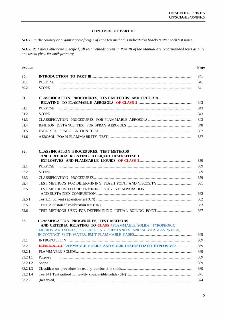
CONTENTS OF PART III
NOTE 1: The country or organisation of origin of each test method is indicated in brackets after each test name.
NOTE 2: Unless otherwise specified, all test methods given in Part III of the Manual are recommended tests as only
one test is given for each property.
Section Page
30. INTRODUCTION TO PART III ..................................................................................................................... 341
30.1 PURPOSE .......................................................................................................................................................... 341
30.2 SCOPE .......................................................................................................................................................... 341
31. CLASSIFICATION PROCEDURES, TEST METHODS AND CRITERIA
RELATING TO FLAMMABLE AEROSOLS OF CLASS 2 .............................................................. 343
31.1 PURPOSE .......................................................................................................................................................... 343
31.2 SCOPE .......................................................................................................................................................... 343
31.3 CLASSIFICATION PROCEDURES FOR FLAMMABLE AEROSOLS ................................................... 343
31.4 IGNITION DISTANCE TEST FOR SPRAY AEROSOLS ............................................................................ 348
31.5 ENCLOSED SPACE IGNITION TEST ............................................................................................................ 352
31.6 AEROSOL FOAM FLAMMABILITY TEST.................................................................................................. 357
32. CLASSIFICATION PROCEDURES, TEST METHODS
AND CRITERIA RELATING TO LIQUID DESENSITIZED
EXPLOSIVES AND FLAMMABLE LIQUIDS OF CLASS 3............................................................. 359
32.1 PURPOSE .......................................................................................................................................................... 359
32.2 SCOPE .......................................................................................................................................................... 359
32.3 CLASSIFICATION PROCEDURES .................................................................................................................. 359
32.4 TEST METHODS FOR DETERMINING FLASH POINT AND VISCOSITY......................................... 361
32.5 TEST METHODS FOR DETERMINING SOLVENT SEPARATION
AND SUSTAINED COMBUSTION................................................................................................................ 362
32.5.1 Test L.1 Solvent separation test (UN) ................................................................................................................ 362
32.5.2 Test L.2 Sustained combustion test (UN) .......................................................................................................... 363
32.6 TEST METHODS USED FOR DETERMINING INITIAL BOILING POINT ........................................ 367
33. CLASSIFICATION PROCEDURES, TEST METHODS
AND CRITERIA RELATING TO CLASS 4FLAMMABLE SOLIDS, PYROPHORIC
LIQUIDS AND SOLIDS, SLEF-HEATING SUBSTANCES AND SUBSTANCES WHICH,
IN CONTACT WITH WATER, EMIT FLAMMABLE GASES................................................................... 369
33.1 INTRODUCTION .................................................................................................................................................. 369
33.2 DIVISION 4.1FLAMMABLE SOLIDS AND SOLID DESENSITIZED EXPLOSIVES ................. 369
33.2.1 FLAMMABLE SOLIDS ....................................................................................................................................... 369
33.2.1.1 Purpose .......................................................................................................................................................... 369
33.2.1.2 Scope .......................................................................................................................................................... 369
33.2.1.3 Classification procedure for readily combustible solids ................................................................................. 369
33.2.1.4 Test N.1 Test method for readily combustible solids (UN) ............................................................................ 371
33.2.2 (Reserved) .......................................................................................................................................................... 374

6
UN/SCETDG/53/INF.5
UN/SCEGHS/35/INF.5
CONTENTS OF PART III (continued)
Section Page
33.2.3 ........ SOLID DESENSITIZED EXPLOSIVES OF DIVISION 4.1 374
33.3 DIVISION 4.2PYROPHORIC AND SELF-HEATING SUBSTANCES .............................................. 375
33.3.1 SUBSTANCES LIABLE TO SPONTANEOUS COMBUSTION ................................................................ 375
33.3.1.1 Purpose .......................................................................................................................................................... 375
33.3.1.2 Scope .......................................................................................................................................................... 375
33.3.1.3 Classification procedure for substances liable to spontaneous combustion ............................................... 375
33.3.1.4 Test N.2 Test method for pyrophoric solids (UN) ............................................................................................ 378
33.3.1.5 Test N.3 Test method for pyrophoric liquids (UN) .......................................................................................... 379
33.3.1.6 Test N.4 Test method for self-heating substances (UN) ................................................................................. 380
33.4 DIVISION 4.3....................................................................................................................................................... 382
33.4.1 SUBSTANCES WHICH IN CONTACT WITH WATER EMIT
FLAMMABLE GASES ...................................................................................................................................... 382
33.4.1.1 Purpose .......................................................................................................................................................... 382
33.4.1.2 Scope .......................................................................................................................................................... 382
33.4.1.3 Classification procedure for substances which in contact with
water emit flammable gases .............................................................................................................................. 382
33.4.1.4 Test N.5 Test method for substances which in contact with
water emit flammable gases (UN)............................................................................................... 383
34. CLASSIFICATION PROCEDURES, TEST METHODS AND CRITERIA
RELATING TO OXIDIZING SUBSTANCES OF DIVISION 5.1..................................................... 385
34.1 PURPOSE .......................................................................................................................................................... 385
34.2 SCOPE .......................................................................................................................................................... 385
34.3 CLASSIFICATION PROCEDURE .................................................................................................................... 385
34.4 TEST METHODS FOR OXIDIZING SUBSTANCES ................................................................................... 386
34.4.1 Test O.1 Test for oxidizing solids (UN) ..................................................................................................... 386
34.4.2 Test O.2 Test for oxidizing liquids (UN) ................................................................................................... 390
34.4.3 Test O.3 Gravimetric test for oxidizing solids (UN) ........................................................................................ 397
35. DETERMINATION OF CHEMICAL INSTABILITY OF GASES
AND GAS MIXTURES ..................................................................................................................................... 405
35.0 INTRODUCTION .................................................................................................................................................. 405
35.1 PURPOSE .......................................................................................................................................................... 405
35.2 SCOPE .......................................................................................................................................................... 405
35.3 CONCENTRATION LIMITS ............................................................................................................................. 405
35.3.1 Generic concentration limits ................................................................................................................................ 405
35.3.2 Specific concentration limits ................................................................................................................................ 406
35.4 TEST METHOD..................................................................................................................................................... 408
35.4.1 Introduction .......................................................................................................................................................... 408
35.4.2 Apparatus and material.......................................................................................................................................... 408
35.4.3 Test procedure........................................................................................................................................................ 409
35.4.4 Safety precautions ................................................................................................................................................. 410

7
UN/SCETDG/53/INF.5
UN/SCEGHS/35/INF.5
CONTENTS OF PART III (continued)
Section Page
35.4.5 Test criteria and method of assessing results ................................................................................................... 410
36. Reserved for classification procedures, test methods
and criteria relating to Class 7......................................................................................................................... 413
37. CLASSIFICATION PROCEDURES, TEST METHODS
AND CRITERIA RELATING TO SUBSTANCES OF CLASS 8 CORROSIVE TO
METALS 415
37.1 PURPOSE .......................................................................................................................................................... 415
37.2 SCOPE .......................................................................................................................................................... 415
37.3 CLASSIFICATION PROCEDURE .................................................................................................................... 415
37.4 TEST METHODS FOR CORROSION TO METALS ................................................................................... 415
37.4.1 Introduction .......................................................................................................................................................... 415
37.4.1.1 Test C.1 Test for determining the corrosive properties of liquids and solids
that may become liquid during transport as dangerous goods of Class 8,
packing group III............................................................................................................................ 415
37.4.2 Apparatus and material.......................................................................................................................................... 415
37.4.3 Procedure .......................................................................................................................................................... 417
37.4.4 Test criteria and method of assessing results ................................................................................................... 418
38. CLASSIFICATION PROCEDURES, TEST METHODS
AND CRITERIA RELATING TO SUBSTANCES AND ARTICLES OF TRANSPORT
CLASS 9 419
38.1 INTRODUCTION .................................................................................................................................................. 419
38.2 AMMONIUM NITRATE FERTILIZERS CAPABLE OF
SELF-SUSTAINING DECOMPOS ITION.................................................................................................. 419
38.2.1 Purpose .......................................................................................................................................................... 419
38.2.2 Scope .......................................................................................................................................................... 419
38.2.3 Classification procedure....................................................................................................................................... 419
38.2.4 Test S.1 "Trough" test for determination of the self-sustaining exothermic
decomposition of fertilizers containing nitrates .............................................................................................. 419
38.3 LITHIUM METAL AND LITHIUM ION BATTERIES .......................................................................... 424
38.3.1 Purpose .......................................................................................................................................................... 424
38.3.2 Scope .......................................................................................................................................................... 424
38.3.4 Procedure .... ...................................................................................................................................................... 429
38.3.4.1 Test T.1 Altitude simulation ........................................................................................................................ 429
38.3.4.2 Test T.2 Thermal test ................................................................................................................................... 429
38.3.4.3 Test T.3 Vibration .......................................................................................................................................... 430
38.3.4.4 Test T.4 Shock ............................................................................................................................................... 430
38.3.4.5 Test T.5 External short circuit ..................................................................................................................... 433
38.3.4.6 Test T.6 Impact .............................................................................................................................................. 433
38.3.4.7 Test T.7 Overcharge.............................................................................................................................................. 434
38.3.4.8 Test T.8 Forced discharge.................................................................................................................................... 435
8
UN/SCETDG/53/INF.5
UN/SCEGHS/35/INF.5
CONTENTS OF PART III (continued)
Section Page
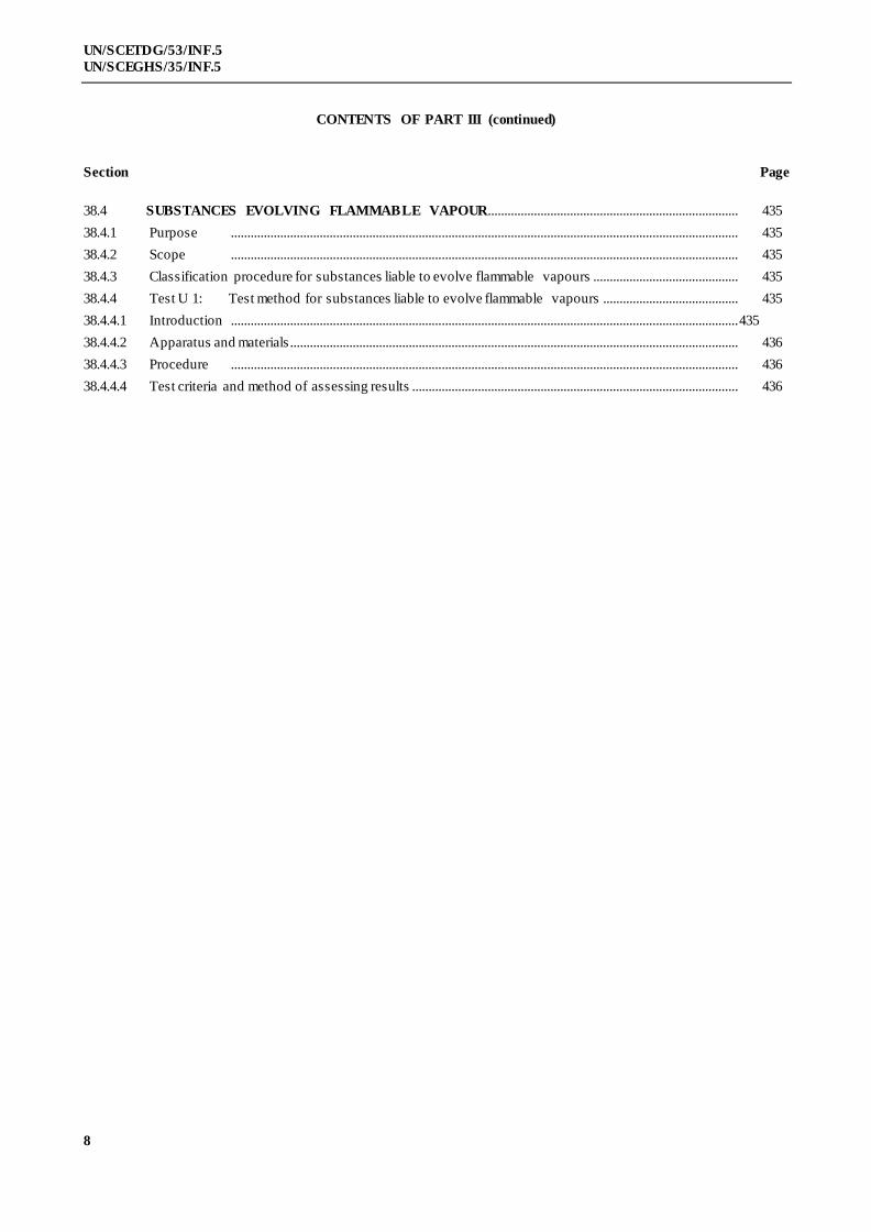
38.4 SUBSTANCES EVOLVING FLAMMABLE VAPOUR............................................................................ 435
38.4.1 Purpose .......................................................................................................................................................... 435
38.4.2 Scope .......................................................................................................................................................... 435
38.4.3 Classification procedure for substances liable to evolve flammable vapours ............................................ 435
38.4.4 Test U 1: Test method for substances liable to evolve flammable vapours ......................................... 435
38.4.4.1 Introduction .......................................................................................................................................................... 435
38.4.4.2 Apparatus and materials ........................................................................................................................................ 436
38.4.4.3 Procedure .......................................................................................................................................................... 436
38.4.4.4 Test criteria and method of assessing results ................................................................................................... 436
9
UN/SCETDG/53/INF.5
UN/SCEGHS/35/INF.5
SECTION 30
INTRODUCTION TO PART III
30.1 Purpose
30.1.1 Part III of the Manual presents the United Nations schemes for the classification of:
(a) Flammable aerosols (see section 31 of this Manual, and special provision 63 of Chapter 3.3 of the Model
Regulations and Chapter 2.3 of the GHS);
(b) Flammable liquids and liquid desensitized explosives of Class 3 (see section 32 of this Manual,
and Chapter 2.3 of the Model Regulations and Chapters 2.6 and 2.17 of the GHS);
(c) Readily combustible solids and solid desensitized explosives of Division 4.1 (see sub-section
33.2 of this Manual, and Chapter 2.4 of the Model Regulations and Chapters 2.7 and 2.17 of
the GHS);
(d) Pyrophoric and self-heating substances, of Division 4.2 (see sub-section 33.3 of this Manual,
and Chapter 2.4 of the Model Regulations and Chapters 2.9, 2.10 and 2.11 of the GHS);
(e) Substances which, in contact with water, emit flammable gases of Division 4.3 (see sub-
section 33.4 of this Manual, and Chapter 2.4 of the Model Regulations and Chapter 2.12 of the
GHS);
(f) Oxidizing substances of Division 5.1 (see section 34 of this Manual, and Chapter 2.5 of the
Model Regulations and Chapters 2.13 and 2.14 of the GHS);
(g) Corrosive properties of substances of class 8 (see section 37 of this Manual, and Chapter 2.8 of
the Model Regulations and Chapter 2.16 of the GHS);
(h) Ammonium nitrate based fertilizers capable of self-sustaining decomposition of Class 9
(see sub-section 38.2 and section 39 of this Manual); and
(i) Lithium cells and batteries of Class 9 (see sub-section 38.3 of this Manual).
30.1.2 Part III contains some classification procedures, test methods and criteria which are also given in the
Model Regulations. Sections 35 and 36 are is reserved, to allow for possible future developments , for Classes 6 and 7
respectively.
30.2 Scope
The appropriate classification procedure should be undertaken before on a new product is offered for
transport. The producer or other applicant for classification of a new product should provide:
(a) Adequate information concerning the names and characteristics of the substance or article;
(b) The results of all relevant tests which have been done; and
(c) The proposed classification with any subsidiary hazard requirements.

11
UN/SCETDG/53/INF.5
UN/SCEGHS/35/INF.5
SECTION 31
CLASSIFICATION PROCEDURES, TEST METHODS AND CRITERIA
RELATING TO FLAMMABLE FLAMMABILITY OF AEROSOLS OF CLASS 2
31.1 Purpose
31.1.1 This section presents the United Nations scheme for the classification of flammable aerosols as either
flammable (Divisions 2.1 / Category 1 or 2) or non-flammable (Division 2.2 / Category 3). The text should be used in
conjunction with the classification principles given in Chapters 2.2 and 3.3 (special provision 63) of the Model
Regulations, Chapter 2.3 of the GHS, the flow charts given here in figures 31.1, 31.2 and 31.3 and the tests
prescriptions given in sub-sections 31.4, 31.5 and 31.6 of this Manual.
31.1.2 The test procedures outlined here adequately assess the relative flammability hazards of flammable
aerosols so that an appropriate classification can be made.
31.1.3 For the purposes of this section the following definitions apply:
Aerosols or aerosol dispensers are non-refillable receptacles meeting the requirements of section 6.2.4 of the Model
Regulations, made of metal glass or plastics and containing a gas, compressed, liquefied or dissolved under pressure,
with or without a liquid, paste or powder, and fitted with a release device allowing the contents to be ejected as solid or
liquid particles in suspension in a gas, as a foam, paste or powder or in a liquid state or in a gaseous state (for transport
purposes the receptacles need to meet the requirements of section 6.2.4 of the Model Regulations);
Flammable components are flammable liquids, flammable solids or flammable gases and gas mixtures. This designation
does not cover pyrophoric, self-heating or water-reactive substances.
NOTE 1: A flammable liquid means a liquid having a flash point of not more than 93 °C. Test methods for determining
the flash point are given in sub-section 32.4 of this Manual;
NOTE 2: For the definition of flammable solids, see paragraph 2.4.2.2 of the Model Regulations and section 2.7.1 of
the GHS. Classification procedures, test methods and criteria relating to flammable solids of Division 4.1 are given
in sub-section 33.2 of this Manual;
NOTE 3: A flammable gas is a gas having a flammable range with air at 20 °C and a standard pressure of 101.3 kPa.
31.2 Scope
31.2.1 Aerosols offered for transport shall be subjected to the classification procedures as set out in special
provision 63 of Chapter 3.3 of the Model Regulations . Aerosols for supply and use shall be subjected to the
classification scheme as set out in section 2.3.2 of the GHS. and, for For flammability, aerosols shall be subjected to the
classification procedures as set out in this section. The classification procedure shall be undertaken before a new
product is offered for transport.
NOTE: Aerosols dispensers not submitted to flammability classification procedures in this sub -section shall
be classified as extremely flammable (Category 1).
31.3 Classification procedure for flammable aerosols
31.3.1 Aerosols shall be classified as non-flammable, flammable or extremely flammable according to their
heat of combustion and to their flammable component contents, as follows:
(a) The aerosol product is classified as extremely flammable (Division 2.1 / Category 1) if:
(i) it the product contains 85% or more flammable components and the chemical heat of
combustion exceeds or is equal to 30 kJ/g, or;

12
UN/SCETDG/53/INF.5
UN/SCEGHS/35/INF.5
(ii) if it meets the criteria for extreme flammability in 31.3.2 for spray aerosols or in 31.3.4
for foam aerosols; and
(b) the aerosol is classified as flammable (Division 2.1 / Category 2) if it meets the criteria for
flammability in 31.3.2 for spray aerosols or in 31.3.4 for foam aerosols; and
(bc) The aerosol product is classified as non-flammable (Division 2.2 / Category 3) if it the product
contains 1% or less flammable components and the chemical heat of combustion is less
than 20 kJ/g.
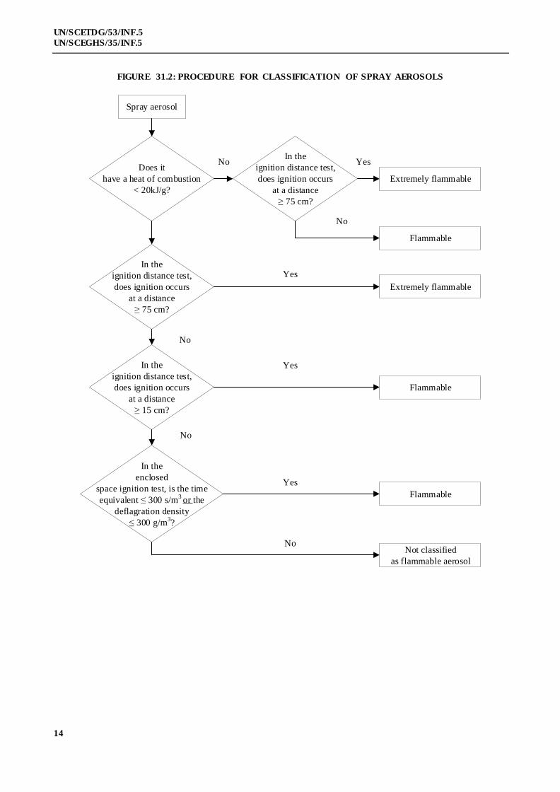
31.3.2 In the case of spray aerosols the classification shall be made taking into account for the chemical heat
of combustion and on the basis of the results of the ignition distance test (see section 31.4 of this Manual)., as follows:
(a) If the chemical heat of combustion is less than 20 kJ/g:
(i) The aerosol is classified as flammable if ignition occurs at a distance equal or greater than 15 cm
but less than 75 cm;
(ii) The aerosol is classified as extremely flammable if ignition occurs at a distance of
75 cm or more;
(iii) If no ignition occurs in the ignition distance test, the enclosed space test shall be
performed and in this case, the aerosol is classified as flammable if the time equivalent
is less than or equal to 300 s/m3 or the deflagration density is less than or equal to
300 g/m3; otherwise the aerosol is classified as non-flammable;
(b) If the chemical heat of combustion is equal to or more than 20 kJ/g, the aerosol is classified as
extremely flammable if ignition occurs at a distance of 75 cm or more; otherwise the aerosol is
classified as flammable.
31.3.3 The chemical heat of combustion shall be determined following one of the methods de scribed in the
following standards: ASTM D 240, ISO/FDIS 13943:1999 (E/F) 86.1 to 86.3 and NFPA 30B.
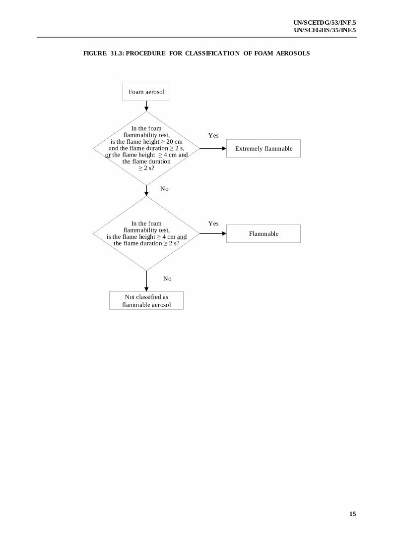
31.3.4 In the case of foam aerosols, the classification shall be made on the basis of the results of the foam
flammability test (see sub-section 31.6 of this Manual).
(a) The aerosol product shall be classified as extremely flammable if:
(i) the flame height is 20 cm or more and the flame duration is 2 s or more; or
(ii) the flame height is 4 cm or more and the flame duration is 7 s or more;
(b) The aerosol product which does not meet the criteria in (a) is classified as flammable if the
flame height is 4 cm or more and the flame duration is 2 s or more.
31.3.5 The classification criteria procedure for aerosols, spray aerosols and foam aerosols is summarized in
figures 31.1, 31.2 and 31.3 respectively.

13
UN/SCETDG/53/INF.5
UN/SCEGHS/35/INF.5
FIGURE 31.1: OVERALL PROCEDURE FOR CLASSIFICATION OF FLAMMABLE AEROSOLS
Aerosol
Not classified as flammable aerosol
Does it
contain 1% or less
flammable components
and does it have a heat of
combustion
< 20 kJ/g?
Does it
contain 85% or more
flammable components
and does it have a heat of
combustion
20 kJ/g?
Extremely flammable
For spray aerosols, go to Figure 31.2
For foam aerosols, go to Figure 31.2
14
UN/SCETDG/53/INF.5
UN/SCEGHS/35/INF.5
FIGURE 31.2: PROCEDURE FOR CLASSIFICATION OF SPRAY AEROSOLS
Spray aerosol
In the
ignition distance test,
does ignition occurs
at a distance
75 cm?
In the
ignition distance test,
does ignition occurs
at a distance
15 cm?
In the
enclosed
space ignition test, is the time
equivalent 300 s/m3
or the
deflagration density
300 g/m3?
NoIn the
ignition distance test,
does ignition occurs
at a distance
75 cm?
Does it
have a heat of combustion
< 20kJ/g?
Not classified
as flammable aerosol
Extremely flammable
Extremely flammable
Flammable
Flammable
Flammable
No
Yes
Yes
Yes
Yes
No
No
No
15
UN/SCETDG/53/INF.5
UN/SCEGHS/35/INF.5
FIGURE 31.3: PROCEDURE FOR CLASSIFICATION OF FOAM AEROSOLS
Foam aerosol
In the foam flammability test,
is the flame height 20 cm and the flame duration 2 s,
or the flame height 4 cm and the flame duration
2 s?
In the foam flammability test,
is the flame height 4 cm and the flame duration 2 s?
Extremely flammable
Flammable
Not classified as
flammable aerosol
Yes
Yes
No
No

16
UN/SCETDG/53/INF.5
UN/SCEGHS/35/INF.5
31.4 Ignition distance test for spray aerosols
31.4.1 Introduction
31.4.1.1 This test standard describes the method to determine the ignition distance of an aerosol spray in order
to assess the associated flame risk. The aerosol is sprayed in the direction of an ignition source at intervals of 15 cm to
observe if ignition and sustained combustion of the spray takes place. Ignition and sustained combustion is defined as
when a stable flame is maintained for at least 5 s. The ignition source is defined as a gas burner with a blue, non-
luminous flame 4-5 cm in height.
31.4.1.2 This test is applicable to aerosol products with a spray distance of 15 cm or more. Aerosol products
with a spray distance of less than 15 cm such as dispensing foams, mousses, gels and pastes or fitted with a metering
valve, are excluded from this test. Aerosol products that dispense foams, mousses, gels or pastes are subject to testing
under the aerosol foam flammability test.
31.4.2 Apparatus and material
31.4.2.1 The following apparatus is required:
Water bath maintained at 20 C accurate to 1 C
Calibrated laboratory scales (balance) accurate to 0.1 g
Chronometer (stopwatch) accurate to 0.2 s
Graduated scale, support and clamp graduations in cm
Gas burner with support and clamp
Thermometer accurate to 1 C
Hygrometer accurate to 5%
Pressure gauge accurate to 0.1 bar
31.4.3 Procedure
31.4.3.1 General requirements
31.4.3.1.1 Before testing, each aerosol dispenser shall be conditioned and then primed by discharging for
approximately 1 s. The purpose of this action is to remove non-homogeneous material from the diptube.
31.4.3.1.2 The instructions of use shall be strictly followed, including whether the dispenser is intended to be
used in the upright or inverted position. When shaking is required, shake immediately before testing.
31.4.3.1.3 The test shall be carried out in a draught-free environment capable of ventilation, with the temperature
controlled at 20 °C ± 5 °C and relative humidity in the range 30 - 80%.
31.4.3.1.4 Each aerosol dispenser is to be tested:
(a) When full according to the complete procedure, with the gas burner in the range of 15 - 90 cm
distance from the actuator of the aerosol can;
(b) When 10 - 12% full nominal (% by mass) only one test, either at 15 cm distance from the
actuator when the spray from a full can did not ignite at all, or at the flame ignition distance of
the spray of a full can plus 15 cm.
31.4.3.1.5 During the test, the can shall be positioned as indicated by label instructions. The ignition source shall
be positioned accordingly.
31.4.3.1.6 The following procedure requires testing the spray at intervals of 15 cm between the burner flame and the
aerosol actuator, in the range of 15 - 90 cm. It is efficient to start at 60 cm distance between burner flame and aerosol
actuator. The distance between burner flame and aerosol actuator shall be increased by 15 cm in the case of an ignition
of the spray at 60 cm distance. The distance shall be decreased by 15 cm in the case of no ignition at 60 cm distance
17
UN/SCETDG/53/INF.5
UN/SCEGHS/35/INF.5
between burner flame and aerosol actuator. The aim of the procedure is to determine the maximum distance between
aerosol actuator and burner flame that leads to sustained combustion of the spray or to determine that ignition could not
be obtained at 15 cm distance between the burner flame and the aerosol's actuator.
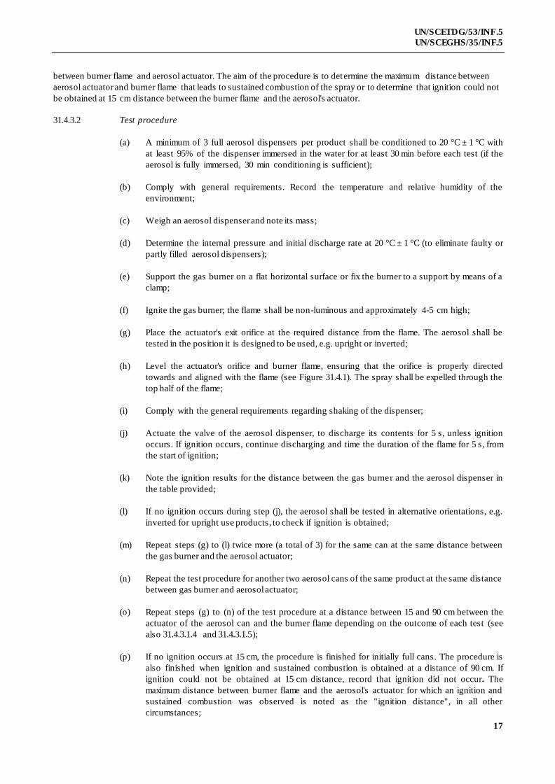
31.4.3.2 Test procedure
(a) A minimum of 3 full aerosol dispensers per product shall be conditioned to 20 °C ± 1 °C with
at least 95% of the dispenser immersed in the water for at least 30 min before each test (if the
aerosol is fully immersed, 30 min conditioning is sufficient);
(b) Comply with general requirements. Record the temperature and relative humidity of the
environment;
(c) Weigh an aerosol dispenser and note its mass;
(d) Determine the internal pressure and initial discharge rate at 20 °C ± 1 °C (to eliminate faulty or
partly filled aerosol dispensers);
(e) Support the gas burner on a flat horizontal surface or fix the burner to a support by means of a
clamp;
(f) Ignite the gas burner; the flame shall be non-luminous and approximately 4-5 cm high;
(g) Place the actuator's exit orifice at the required distance from the flame. The aerosol shall be
tested in the position it is designed to be used, e.g. upright or inverted;
(h) Level the actuator's orifice and burner flame, ensuring that the orifice is properly directed
towards and aligned with the flame (see Figure 31.4.1). The spray shall be expelled through the
top half of the flame;
(i) Comply with the general requirements regarding shaking of the dispenser;
(j) Actuate the valve of the aerosol dispenser, to discharge its contents for 5 s, unless ignition
occurs. If ignition occurs, continue discharging and time the duration of the flame for 5 s, from
the start of ignition;
(k) Note the ignition results for the distance between the gas burner and the aerosol dispenser in
the table provided;
(l) If no ignition occurs during step (j), the aerosol shall be tested in alternative orientations, e.g.
inverted for upright use products, to check if ignition is obtained;
(m) Repeat steps (g) to (l) twice more (a total of 3) for the same can at the same distance between
the gas burner and the aerosol actuator;
(n) Repeat the test procedure for another two aerosol cans of the same product at the same distance
between gas burner and aerosol actuator;
(o) Repeat steps (g) to (n) of the test procedure at a distance between 15 and 90 cm between the
actuator of the aerosol can and the burner flame depending on the outcome of each test (see
also 31.4.3.1.4 and 31.4.3.1.5);
(p) If no ignition occurs at 15 cm, the procedure is finished for initially full cans. The procedure is
also finished when ignition and sustained combustion is obtained at a distance of 90 cm. If
ignition could not be obtained at 15 cm distance, record that ignition did not occur. The
maximum distance between burner flame and the aerosol's actuator for which an ignition and
sustained combustion was observed is noted as the "ignition distance", in all other
circumstances;

18
UN/SCETDG/53/INF.5
UN/SCEGHS/35/INF.5
(q) One test shall also be conducted on 3 cans of 10 - 12% nominal fill level. These cans shall be
tested at a distance between the aerosol's actuator and the burner flame of "the flame ignition
distance of full cans + 15 cm";
(r) Discharge an aerosol can to a 10 - 12% nominal fill level (by mass) in bursts of 30 s maximum.
Observe a 300 s minimum time period between bursts. During this interim period dispensers
shall be placed in the water bath for conditioning;
(s) Repeat steps (g) to (n) for 10 - 12% nominal fill aerosol cans, omitting steps (l) and (m). This
test shall only be performed with the aerosol in one position, e.g. upright or inverted,
corresponding with that which produced the ignition (if any) for filled cans;
(t) Record all results in the Table 31.4 as shown below.
31.4.3.2.1 All experiments shall be performed in a fume hood in a room that may be well ventilated. Ventilation
of the fume hood and room can be applied for at least 3 min after each test. Take all necessary safety precautions to
prevent the inhalation of combustion products.
31.4.3.2.2 The cans with a 10 - 12% nominal fill level shall be tested only once. The result tables need only one
result per can indicated.
31.4.3.2.3 When the test in the position in which the dispenser is designed to be used gives a negative result , the
test shall be repeated in the position of the dispenser most likely to result in a positive result.
31.4.4 Test criteria and method of assessing results
31.4.4.1 All the results shall be recorded. Table 31.4 below shows the model of "result table" to be used.
Table 31.4: MODEL OF "RESULT TABLE"
Date Temperature
Relative humidity C
%
Name of product
Net volume Can 1 Can 2 Can 3
Initial level
of filling
% % %
Dispenser distance
Test 1 2 3 1 2 3 1 2 3
15 cm Ignition?
Y or N
30 cm Ignition?
Y or N
45 cm Ignition?
Y or N
60 cm Ignition?
Y or N
75 cm Ignition?
Y or N
90 cm Ignition?
Y or N
Observations –
including can
position

19
UN/SCETDG/53/INF.5
UN/SCEGHS/35/INF.5
31.4.4.2 Spray aerosols shall be classified as flammable, extremely flammable or non flammable according to
the following criteria:
Criteria UN Model Regulations
Division
GHS
Category
Ignition occurs at a distance of 75 cm or more,
regardless of the heat of combustion
2.1 1
Ignition occurs at a distance of less than 75 cm, with a
chemical heat of combustion equal to or more than
20 kJ/g
2.1 2
Ignition occurs at a distance equal or greater than 15 cm
but less than 75 cm, with a chemical heat of combustion
less than 20 kJ/g
2.1 2
No ignition occurs in the ignition distance test and the
chemical heat of combustion is less than 20 kJ/g
Perform enclosed space ignition test
described in section 31.5
(a) An aerosol with a chemical heat of combustion less than 20 kJ/g is classified as flammable if ignition
occurs at a distance equal or greater than 15 cm but less than 75 cm;
(b) An aerosol with a chemical heat of combustion less than 20 kJ/g is classified as extremely
flammable if ignition occurs at a distance of 75 cm or more;
(c) If for an aerosol with a chemical heat of combustion less than 20 kJ/g, no ignition occurs in the
ignition distance test, the enclosed space ignition test described in sub-section 31.5 of this
Manual shall be performed;
(d) An aerosol with a chemical heat of combustion equal to or more than 20 kJ/g is classified as extremely
flammable if ignition occurs at a distance of 75 cm or more. Otherwise the aerosol is classified as flammable.
Figure 31.4.1: SYSTEM FOR IGNITION DISTANCE TEST
20
UN/SCETDG/53/INF.5
UN/SCEGHS/35/INF.5
31.5 Enclosed space ignition test
31.5.1 Introduction
31.5.1.1 This test standard describes the method to assess the flammability of products emerging from aerosol
dispensers due to their propensity to ignite in an enclosed or confined space. The contents of an aerosol dispenser are
sprayed into a cylindrical test vessel containing a burning candle. If an observable ignition occurs, the elapsed time and
amount discharged is noted.
31.5.2 Apparatus and material
31.5.2.1 The following apparatus is required:
Chronometer (stopwatch) accurate to ± 0.2 s
Water bath maintained at 20 °C accurate to ± 1 °C
Calibrated laboratory scales (balance) accurate to ± 0.1 g
Thermometer accurate to ± 1 °C
Hygrometer accurate to ± 5%
Pressure gauge accurate to ± 0.1 bar
Cylindrical test vessel as detailed below
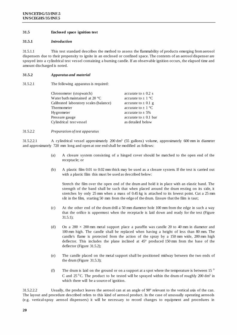
31.5.2.2 Preparation of test apparatus
31.5.2.2.1 A cylindrical vessel approximately 200 dm3 (55 gallons) volume, approximately 600 mm in diameter
and approximately 720 mm long and open at one end shall be modified as follows:
(a) A closure system consisting of a hinged cover should be matched to the open end of the
receptacle; or
(b) A plastic film 0.01 to 0.02 mm thick may be used as a closure system. If the test is carried out
with a plastic film this must be used as described below:
Stretch the film over the open end of the drum and hold it in place with an elastic band. The
strength of the band shall be such that when placed around the drum resting on its side, it
stretches by only 25 mm when a mass of 0.45 kg is attached to its lowest point. Cut a 25 mm
slit in the film, starting 50 mm from the edge of the drum. Ensure that the film is taut;
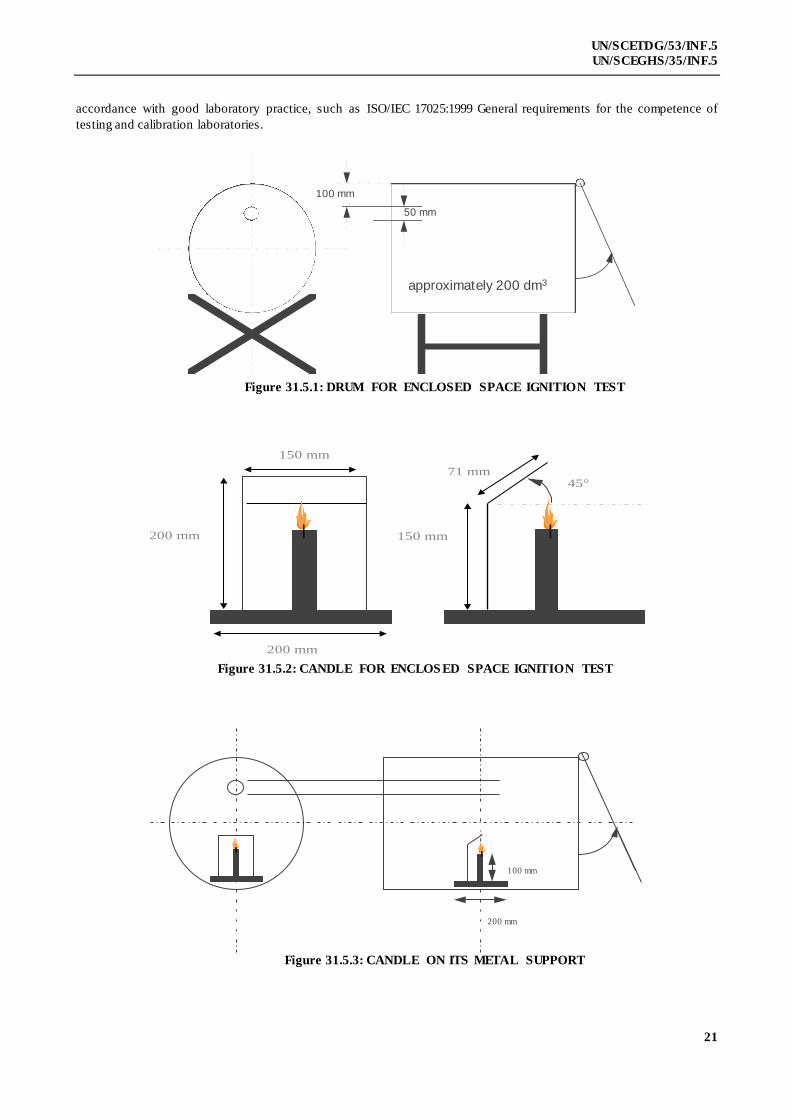
(c) At the other end of the drum drill a 50 mm diameter hole 100 mm from the edge in such a way
that the orifice is uppermost when the receptacle is laid down and ready for the test (Figure
31.5.1);
(d) On a 200 × 200 mm metal support place a paraffin wax candle 20 to 40 mm in diameter and
100 mm high. The candle shall be replaced when having a height of less than 80 mm. The
candle's flame is protected from the action of the spray by a 150 mm wide, 200 mm high
deflector. This includes the plane inclined at 45° produced 150 mm from the base of the
deflector (Figure 31.5.2);
(e) The candle placed on the metal support shall be positioned midway between the two ends of
the drum (Figure 31.5.3);
(f) The drum is laid on the ground or on a support at a spot where the temperature is between 15
C and 25 C. The product to be tested will be sprayed within the drum of roughly 200 dm3 in
which there will be a source of ignition.
31.5.2.2.2 Usually, the product leaves the aerosol can at an angle of 90° relevant to the vertical axis of the can.
The layout and procedure described refers to this kind of aerosol product. In the case of unusually operating aerosols
(e.g. vertical-spray aerosol dispensers) it will be necessary to record changes to equipment and procedures in
21
UN/SCETDG/53/INF.5
UN/SCEGHS/35/INF.5
accordance with good laboratory practice, such as ISO/IEC 17025:1999 General requirements for the competence of
testing and calibration laboratories.
approximately 200 dm3
50 mm
100 mm
Figure 31.5.1: DRUM FOR ENCLOSED SPACE IGNITION TEST
45°
150 mm
200 mm
71 mm
200 mm
(second
150 mm
Figure 31.5.3: CANDLE ON ITS METAL SUPPORT
Figure 31.5.2: CANDLE FOR ENCLOS ED SPACE IGNITION TEST
100 mm
200 mm

22
UN/SCETDG/53/INF.5
UN/SCEGHS/35/INF.5
31.5.3 Procedure
31.5.3.1 General requirements
31.5.3.1.1 Before testing, each aerosol dispenser shall be conditioned and then primed by discharging for
approximately 1 second. The purpose of this action is to remove non-homogeneous material from the diptube.
31.5.3.1.2 The instructions of use shall be strictly followed, including whether the dispenser is intended to be
used in the upright or inverted position. When shaking is required, shake immediately before testing.
31.5.3.1.3 The tests shall be carried out in a draught-free environment capable of ventilation, with the
temperature controlled at 20 °C ± 5 °C and relative humidity in the range 30 - 80%.
31.5.3.2 Test procedure
(a) A minimum of 3 full aerosol dispensers per product shall be conditioned to 20 °C ± 1 °C in a water bath
with at least 95% of the dispenser immersed in the water for at least 30 min (if the aerosol is fully immersed, 30 min
conditioning is sufficient);
(b) Measure or calculate the actual volume of the drum in dm3;
(c) Comply with general requirements. Record the temperature and relative humidity of the
environment;
(d) Determine the internal pressure and initial discharge rate at 20 °C ± 1 °C (to eliminate faulty or
partly filled aerosol dispensers);
(e) Weigh one of the aerosol dispensers and note its mass;
(f) Light the candle and apply the closure system (cover or plastic film);
(g) Place the aerosol dispenser actuator orifice 35 mm or closer for a wide spray product, from the
centre of the entrance hole in the drum. Start the chronometer (stopwatch) and following the
instructions for use of the product; direct the spray towards the centre of the opposite extremity
(cover or plastic film). The aerosol shall be tested in the position it is designed to be used, e.g.
upright or inverted;
(h) Spray until ignition occurs. Stop the chronometer and note the time elapsed. Re-weigh the
aerosol dispenser and note its mass;
(i) Ventilate and clean the drum removing any residue likely to affect subsequent tests. Allow the
drum to cool if necessary;
(j) Repeat the test procedure steps (d) to (i) for another two aerosol dispensers of the same product
(3 in total, note: each dispenser is only tested once);
31.5.4 Test criteria and method of assessing results
31.5.4.1 A test report containing the following information shall be drawn up:
(a) The product tested and its references;
(b) The internal pressure and discharge rate of the aerosol dispenser;
(c) The temperature and relative air humidity of the room;
(d) For each test, the discharge time (s) needed to achieve ignition (if the product does not ignite,
state this);
23
UN/SCETDG/53/INF.5
UN/SCEGHS/35/INF.5
(e) The mass of the product sprayed during each test (in g);
(f) The actual volume of the drum (in dm3).
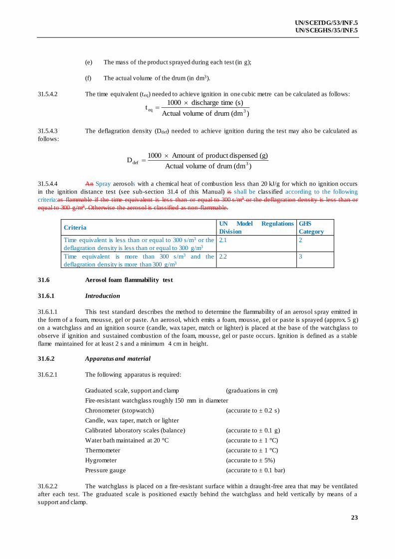
31.5.4.2 The time equivalent (teq) needed to achieve ignition in one cubic metre can be calculated as follows:
)(dm drum of volumeActual
)(s timedischarge 1000t
3eq
31.5.4.3 The deflagration density (Ddef) needed to achieve ignition during the test may also be calculated as
follows:
)(dm drum of volumeActual
(g) dispensedproduct ofAmount 1000D
3def
31.5.4.4 An Spray aerosols with a chemical heat of combustion less than 20 kJ/g for which no ignition occurs
in the ignition distance test (see sub-section 31.4 of this Manual) is shall be classified according to the following
criteria:as flammable if the time equivalent is les s than or equal to 300 s/m3 or the deflagration density is less than or
equal to 300 g/m3. Otherwise the aerosol is classified as non-flammable.
Criteria UN Model Regulations
Division
GHS
Category
Time equivalent is less than or equal to 300 s/m3 or the
deflagration density is less than or equal to 300 g/m3
2.1 2
Time equivalent is more than 300 s/m3 and the
deflagration density is more than 300 g/m3
2.2 3
31.6 Aerosol foam flammability test
31.6.1 Introduction
31.6.1.1 This test standard describes the method to determine the flammability of an aerosol spray emitted in
the form of a foam, mousse, gel or paste. An aerosol, which emits a foam, mousse, gel or paste is sprayed (approx. 5 g)
on a watchglass and an ignition source (candle, wax taper, match or lighter) is placed at the base of the watchglass to
observe if ignition and sustained combustion of the foam, mousse, gel or paste occurs. Ignition is defined as a stable
flame maintained for at least 2 s and a minimum 4 cm in height.
31.6.2 Apparatus and material
31.6.2.1 The following apparatus is required:
Graduated scale, support and clamp (graduations in cm)
Fire-resistant watchglass roughly 150 mm in diameter
Chronometer (stopwatch) (accurate to ± 0.2 s)
Candle, wax taper, match or lighter
Calibrated laboratory scales (balance) (accurate to ± 0.1 g)
Water bath maintained at 20 °C (accurate to ± 1 °C)
Thermometer (accurate to ± 1 °C)
Hygrometer (accurate to ± 5%)
Pressure gauge (accurate to ± 0.1 bar)
31.6.2.2 The watchglass is placed on a fire-resistant surface within a draught-free area that may be ventilated
after each test. The graduated scale is positioned exactly behind the watchglass and held vertically by means of a
support and clamp.
24
UN/SCETDG/53/INF.5
UN/SCEGHS/35/INF.5
31.6.2.3 The scale is positioned in such a way that its origin is on a level with the watchglass base in a
horizontal plane.
31.6.3 Procedure
31.6.3.1 General requirements
31.6.3.1.1 Before testing, each aerosol dispenser shall be conditioned and then primed by discharging for
approximately 1 second. The purpose of this action is to remove non-homogeneous material from the diptube.
31.6.3.1.2 The instructions of use shall be strictly followed, including whether the dispenser is intended to be
used in the upright or inverted position. When shaking is required, shake immediately before testing.
31.6.3.1.3 The tests shall be carried out in a draught-free environment capable of ventilation, with
the temperature controlled at 20 °C ± 5 °C and relative humidity in the range of 30–80%.
31.6.3.2 Test procedure
(a) A minimum of four full aerosol dispensers per product shall be conditioned to 20 °C ± 1 °C with at least
95% of the dispenser immersed in the water for at least 30 min before each test (if the aerosol is fully immersed,
30 min conditioning is sufficient);
(b) Comply with general requirements. Record the temperature and relative humidity of the
environment;
(c) Determine the internal pressure at 20 °C ± 1 °C (to eliminate faulty or partly filled aerosol
dispensers);
(d) Measure the discharge or flow rate of the aerosol product to be examined, so that the amount of
test product dispensed can be more accurately gauged;
(e) Weigh one of the aerosol dispensers and note its mass;
(f) On the basis of the measured discharge or flow rate and following the manufacturer's
instructions, release approximately 5 g of the product onto the centre of the clean watchglass
with the aim of producing a mound no higher than 25 mm;
(g) Within 5 s of completion of discharge, apply the source of ignition to the edge of the sample at
its base and at the same time start the chronometer (stopwatch). If necessary, the ignition
source shall be removed from the edge of the sample after approximately two seconds, in order
to clearly observe if ignition has occurred. If no ignition of the sample is apparent, the ignition
source shall be reapplied to the edge of the sample;
(h) If ignition occurs note the following points:
(i) The maximum height of the flame in cm above the base of the watchglass;
(ii) The flame duration in s;
(iii) Dry and re-weigh the aerosol dispenser and calculate the mass of the released product;
(i) Ventilate the test area immediately after each test;
(j) If ignition is not obtained and the released product remains in the form of a foam or paste
throughout its period of use, steps (e) to (i) should be repeated. Allow the product to stand for
30 s, 1 min, 2 min or 4 min before applying the ignition source;

25
UN/SCETDG/53/INF.5
UN/SCEGHS/35/INF.5
(k) Repeat the test procedure steps (e) to (j) twice more (a total of 3) for the same can;
(l) Repeat the test procedure steps (e) to (k) for another two aerosol cans (3 cans in total) of the
same product.
31.6.4 Test criteria and method of assessing results
31.6.4.1 A test report containing the following information shall be drawn up:
(a) Whether the product ignites;
(b) Maximum flame height in cm;
(c) Duration of flame in s;
(d) The mass of the product tested.
31.6.4.2 The Foam aerosols product shall be classified according to the following criteria:as extremely
flammable if the flame height is 20 cm or more and the flame duration is 2 s or more; or if the flame duration is 7 s or
more and the flame height is 4 cm or more.
Criteria UN Model Regulations
Division
GHS
Category
Flame height is 20 cm or more and the flame duration is 2 s
or more
2.1 1
Flame height is 4 cm or more and the flame duration is 7 s or
more
2.1 1
Flame height is 4 cm or more and the flame duration is 2 s or
more
2.1 2
Flame height is 4 cm or less and the flame duration is 2 s or
less (if any)
2.2 3

27
UN/SCETDG/53/INF.5
UN/SCEGHS/35/INF.5
SECTION 32
CLASSIFICATION PROCEDURES, TEST METHODS AND
CRITERIA RELATING TO LIQUID DESENSITIZED EXPLOSIVES
AND FLAMMABLE LIQUIDS OF CLASS 3
32.1 Purpose
This section presents the United Nations scheme for the classification of liquid desensitized
explosives and flammable liquids of (Class 3 / Categories 1 to 4)(see Chapter 2.3 of the Model Regulations). The text
should be used in conjunction with the class ification principles given in Chapter 2.3 of the Model Regulations , Chapter
2.6 of the GHS and the test methods given in sub-sections 32.4 and 32.5 of this Manual. Note 2 to paragraph 2.1.2.2 of
the GHS should also be taken into consideration.
32.2 Scope
32.2.1 Liquid desensitized explosives are explosive substances which are dissolved or suspended in water or
other liquid substances, to form a homogeneous liquid mixture to suppress their explosive properties (see 2.3.1.4 of the
Model Regulations).
32.2.2 Substances are classified listed in this class as flammable liquids only when their flash point is not
more than 60 °C in a closed-cup test, or not more than 65.6 °C in an open-cup test or, in the case of substances
transported or offered for transport at elevated temperatures, when they give off a flammable vapour at a temperature at
or below the maximum transport temperature. However, liquids with a flash point of more than 35 °C and not more than
60 °C may be regarded as non-flammable for some regulatory purposes (e.g. transport) if they , which do not sustain
combustion (i.e. negative results have been obtained in the sustainability test L.2 in sub -section 32.5.2 of this Manual),
need not to be considered as flammable liquids for the purposes of the Model Regulations.
32.2.3 Flammable liquids listed by name in the dangerous goods list of (Chapter 3.2 of the Model
Regulations) in this class by name should be regarded as chemically pure. In practice, goods shipped under the name of
such substances are often commercial products which contain other added substances or impurities. Therefore, it may
occur that liquids which are not included in the list because their flash point in their pure state is more than 60 °C in a
closed-cup test, or more than 65.6 °C in an open-cup test, may be offered for transport classified as “generic” or “not
otherwise specified” dangerous goods commercial products with a flash point at or below that limit. Moreover, liquids
which would be listed, in their pure state, in packing group III / Category 3 could in fact be included in packing group II
/ Category 3 as commercial products because of the presence of added substances or impurities.
32.2.4 For these reasons caution should be exercised when using the lists, as they are on ly guides. In the
event of doubt, the flash point of substances should be tested experimentally.
32.2.5 Liquids are considered to be unable to sustain combustion for the purposes of the Model Regulations
(i.e. they do not sustain combustion under defined test conditions) if they have passed a yield negative when submitted
to suitable combustibility test (see section 32.5.2) or if their fire point, according to ISO 2592, is greater than 100 °C or
if they are miscible solutions with a water content of more than 90% by mass.
32.3 Classification procedures
32.3.1 Flammable liquids
32.3.1.1 Table 32.1 should be used for the determination of the hazard grouping of a liquid that presents a
hazard due to flammability.

28
UN/SCETDG/53/INF.5
UN/SCEGHS/35/INF.5
Table 32.1: HAZARD GROUPING BASED ON FLAMMABILITY
Criteria UN Model Regulations
Packing group
GHS
Category
Flash point < 23 °C and initial boiling point 35 °C I 1
Flash point < 23 °C and initial boiling point > 35 °C II 2
Flash point 23 °C and 60 °C and initial boiling point > 35 °C III 3
Flash point > 60 °C and 93 °C Not applicable 4
Note: the criterion of initial boiling point > 35 °C for Packing group III / Category 3 is currently not used in GHS.
32.3.1.2 For liquids whose only hazard is flammability, the packing group for the substance is shown in the
hazard grouping shown in Table 32.1.
32.3.1.3 For a liquid with additional hazard(s), the hazard packing group determined from Table 32.1 and the
hazard packing group based on the severity of the additional risk(s) hazard(s) should be considered. In such cases, the
table of precedence of hazard characteristics in Chapter 2.0, section 2.0.3 of the Model Regulations, should be used to
determine the correct classification of the liquid. The hazard grouping packing group indicating the highest degree of
danger based on the different hazards of a substance then becomes the packing group for the such a substance.
Table 32.1: HAZARD GROUPING BASED ON FLAMMABILITY
Packing Group Flash Point (Closed-cup) Initial Boiling Point
I
II
III
-
< 23 °C
≥ 23 °C, 60 °C
≤ 35 °C
> 35 °C
> 35 °C
32.3.2 Liquid desensitized explosives
32.3.2.1 This sub-section presents the United Nations Model Regulations scheme for the classification of
liquid desensitized explosives as flammable liquids of Class 3 (see paragraph 2.3.1.4 of the Model Regulations and note
2 to paragraph 2.1.1.1 of the GHS). Liquid desensitized explosives are substances which are dissolved o r suspended in
water or other liquid substances to form a homogeneous liquid mixture in order to suppress their explosives properties.
32.3.2.2 New products which are thermally stable and have, or are suspected of having, explosive properties
should first be considered for Class 1 and the Class 1 acceptance procedure and, if necessary, the assignment procedure
applied.
32.3.2.32 Where a substance meets the criteria for classification as an explosive is assigned to Class 1
but is diluted to be exempted from Class 1 this class by test series 6 (see section 16), this diluted substance, when
meeting the classification criteria or definition for another hazard class or division, should be classified in that class or
division at the highest concentration which exempts it from the class of explosivesClass 1. When sufficiently diluted,
such substances may be deemed to be non-dangerous for some regulatory purposes (e.g. transport) (see also paragraph
2.1.3.56.3 of the Model Regulations).
32.3.2.4 The classification scheme of liquid desensitized explosives for supply and use (including
storage) according to the Globally Harmonized System of Classification and Labelling of Chemicals (GHS) is referred
to given in section 51.

29
UN/SCETDG/53/INF.5
UN/SCEGHS/35/INF.5
32.4 Test methods used for determining flash point and viscosity
32.4.1 Tests for nNon-viscous flammable liquids
The following methods for determining the flash point of flammable liquids may be used:
International standards:
ISO 1516
ISO 1523
ISO 2719
ISO 13736
ISO 3679
ISO 3680
National standards:
American Society for Testing Materials International, 100 Barr Harbor Drive, PO Box C700, West Conshohocken,
Pennsylvania, USA 19428-2959:
ASTM D3828-07a, Standard Test Methods for Flash Point by Small Scale Closed Cup Tester
ASTM D56-05, Standard Test Method for Flash Point by Tag Closed Cup Tester
ASTM D3278-96(2004)e1, Standard Test Methods for Flash Point of Liquids by Small Scale Closed -
Cup Apparatus
ASTM D93-08, Standard Test Methods for Flash Point by Pensky-Martens Closed Cup Tester
Association française de normalisation, AFNOR, 11, rue de Pressensé, 93571 La Plaine Saint -Denis Cedex:
French Standard NF M 07 - 019
French Standards NF M 07 - 011 / NF T 30 - 050 / NF T 66 - 009
French Standard NF M 07 - 036
Deutsches Institut für Normung, Burggrafenstr. 6, D-10787 Berlin:
Standard DIN 51755 (flash points below 65 °C)
State Committee of the Council of Ministers for Standardization, 113813, GSP, Moscow, M-49 Leninsky Prospect, 9:
GOST 12.1.044-84.
32.4.2 Tests for vViscous flammable substances with a flash point of less than 23 °C
32.4.2.1 The hazard group of paints, enamels, lacquers, varnishes, adhesives, polishes and other viscous
flammable liquids substances of Class 3 with a flash point of less than 23 °C is determined as per sub-section 2.3.2.2 of
the Model Regulations by reference to:
(a) The viscosity expressed as the flow-time in seconds (see 32.4.3);
(b) The closed-cup flash point (see 32.4.2.2); and
(c) A solvent separation test (see 32.5.1).
32.4.2.2 The closed-cup flash point is determined according to the ISO method ISO 1523:1983 for paints and
varnishes. Where the temperature of the flash point is too low for the use of water in the water bath, the following
modifications should be made:
30
UN/SCETDG/53/INF.5
UN/SCEGHS/35/INF.5
(a) Use ethylene glycol in the water bath or other suitable similar container;
(b) Where appropriate, a refrigerator may be used to cool the sample and apparatus to below the
temperature required by the method for the expected flash point. For lower temperatures, the
sample and equipment should be cooled to a suitable temperature - for example, by adding of
solid carbon dioxide slowly to the ethylene glycol, the sample being similarly cooled in a
separate container of ethylene glycol;
(c) In order to obtain reliable flash points, it is important that the recommended rate of temperature
rise for the sample during testing is not exceeded. Depending on the size of the water bath and
the amount of ethylene glycol it contains, it may be necessary partially to insulate the water
bath to achieve a sufficiently slow rate of temperature rise.
32.4.3 Viscosity test
The flow-time in seconds is determined at 23 °C using the ISO standard cup with a 4 mm jet
(ISO 2431:1984). Where the flow-time exceeds 100 seconds, a second test is carried out using the ISO standard cup
with a 6 mm jet.
32.5 Test methods for determining solvent separation and sustained combustion
32.5.1 Test L.1: Solvent separation test
32.5.1.1 Introduction
This test is used to determine the extent of solvent separation in viscous liquids such as paints,
enamels, varnishes, adhesives and polishes with a flash point of less than 23 °C.
32.5.1.2 Apparatus and materials
A stoppered 100 ml measuring cylinder is required of approximately 25 cm total height and of a
uniform internal diameter of approximately 3 cm over the calibrated section.
32.5.1.3 Procedure
The paint should be stirred to obtain a uniform consistency and poured in up to the 100 ml mark. The
stopper should be inserted and the cylinder left standing undisturbed for 24 hours. After 24 hours, the height of the
upper separated layer should be measured.
32.5.1.4 Test criteria and method of assessing results
The height of the upper separated layer should be expressed as a percentage of the total height of the
sample. If less than 3% of clear solvent separates out then the substance may be considered for inclusion in packing
group III (see 2.3.2.2 of the Model Regulations) or may nit be subject to the Moedel Regulations (see 2.3.2.5 of the
Model Regulations)32.3.1.6 and 32.3.1.7).
32.5.2 Test L.2: Sustained combustibility test
32.5.2.1 Introduction
This test is used to determine if a substance sustains combustion when heated under the test conditions
and exposed to a flame. A metal block with a concave depression (sample well) is heated to a specified temperature. A
specified volume of the substance under test is transferred to the well and its ability to sustain combustion is note d after
application and subsequent removal of a standard flame under specified conditions.
32.5.2.2 Apparatus and materials
31
UN/SCETDG/53/INF.5
UN/SCEGHS/35/INF.5
32.5.2.2.1 A combustibility tester is used consisting of a block of aluminium alloy or other corrosion resistant
metal of high thermal conductivity. The block has a concave well and a pocket drilled to take a thermometer. A small
gas jet assembly on a swivel is attached to the block. The handle and gas inlet for the gas jet may be fitted at any
convenient angle to the gas jet. A suitable apparatus is shown in Figure 32.5.2.1 and the eEssential diagrams for a
suitable apparatus are given in figures 32.5.2.1 and 32.5.2.2. The following apparatus is also required:
(a) Gauge, for checking that the height of the centre of the gas jet above the top of the sample well
is 2.2 mm (see Figure 32.5.2.1);
(b) Thermometer, mercury in glass, for horizontal operation, with a sensitivity not less
than 1 mm/°C, or other measuring device of equivalent sensitivity permitting reading at 0.5 °C
intervals. When in position in the block, the thermometer bulb should be surrounded with
thermally conducting thermoplastic compound;
(c) Hotplate, fitted with a temperature-control device (Other types of apparatus with suitable
temperature-control facilities may be employed to heat the metal block.);
(d) Stopwatch, or other suitable timing device;
(e) Syringe, capable of delivering 2.0 ml to an accuracy of ± 0.1 ml;
(f) Fuel, butane.
32.5.2.2.2 The sample should be representative of the substance to be tested and should be supplied and kept in a
tightly closed container prior to the test. Because of the possibility of loss of volatile constituents, the sample should
receive only the minimum treatment to ensure its homogeneity. After removing each test portion, the sample container
should be immediately closed tightly to ensure that no volatile components escape from the container; if this closure is
incomplete, an entirely new sample should be taken.
32.5.2.3 Procedure
32.5.2.3.1 It is essential that the apparatus is set up in a completely draught-free area1 and in the absence of
strong light to facilitate observation of flash, flame, etc.
32.5.2.3.2 Place the metal block on the hotplate or heat the metal block by other suitable means so that its
temperature, as indicated by the thermometer placed in the metal block, is maintained at the specified temperature
within a tolerance of ± 1 °C. The test temperature is 60.5 °C or 75 °C (see 32.5.2.3.8). Correct this temperature for the
difference in barometric pressure from the standard atmospheric pressure (101.3 kPa) by raising the test temperature for
a higher pressure, or lowering the test temperature for a lower pressure, by 1.0 °C for each 4 kPa difference. Ensure that
the top of the metal block is exactly horizontal. Use the gauge to check that the jet is 2.2 mm above the top of the well
when in the test position.
32.5.2.3.3 Light the butane with the jet away from the test position (i.e. in the "off" position, away from the
well). Adjust the size of the flame so that it is 8 mm to 9 mm high and approximately 5 mm wide.
32.5.2.3.4 Using the syringe, take from the sample container at least 2 ml of the sample and rapidly transfer a test
portion of 2.0 ml ± 0.1 ml to the well of the combustibility tester and immediately start the timing device.
32.5.2.3.5 After a heating time of 60 s, by which time the test portion is deemed to have reached its equilibrium
temperature, and if the test fluid has not ignited, swing the test flame into the test position over the edge of the pool of
liquid. Maintain it in this position for 15 s and then return it to the "off" position whilst observing the behaviour of the
test portion. The test flame should remain alight throughout the test.
32.5.2.3.6 The test should be performed in triplicate. For each test observe and record:
1 Warning - do not carry out the test in a small confined area (for example, a glove box) because of
the hazard of explosions.
32
UN/SCETDG/53/INF.5
UN/SCEGHS/35/INF.5
(a) Whether there is ignition and sustained combustion or flashing, or neither, of the test portion
before the test flame is moved into the test position; and
(b) Whether the test portion ignites while the test flame is in the test position, and, if so, how long
combustion is sustained after the test flame is returned to the "off" position.
32.5.2.3.7 If sustained combustion, interpreted in accordance with 32.5.2.4, is not found, repeat the complete
procedure with new test portions, but with a heating time of 30 s.
32.5.2.3.8 If sustained combustion, interpreted in accordance with 32.5.2.4, is not found at a test temperature of
60.5 °C, repeat the complete procedure with new test portions, but at a test temperature of 75 °C.
32.5.2.4 Test criteria and method of assessing results
The substance should be assessed either as not sustaining combustion or as sustaining combustion.
Sustained combustion should be reported at either of the heating times or tempera tures if one of the following occurs
with any of the test portions:
(a) When the test flame is in the "off" position, the test portion ignites and sustains combustion; or
(b) The test portion ignites while the test flame is in the test position, maintained for 15 s, and
sustains combustion for more than 15 s after the test flame has been returned to the "off"
position.
Intermittent flashing should not be interpreted as sustained combustion. Normally, at the end of 15 s, the combustion
has either clearly ceased or continues. In cases of doubt, the substance should be deemed to sustain combustion.

33
UN/SCETDG/53/INF.5
UN/SCEGHS/35/INF.5
(A) Thermometer
(B) Stop
(C) Handle
(D) Test gas jet
(E) Sample well
Figure 32.5.2.1: COMBUSTIBILITY TESTER

34
UN/SCETDG/53/INF.5
UN/SCEGHS/35/INF.5
(A) Butane gas inlet
(B) Test flame
(C) Sample well
Figure 32.5.2.2: TEST GAS JET AND FLAME
35
UN/SCETDG/53/INF.5
UN/SCEGHS/35/INF.5
32.6 Test methods used for determining initial boiling point
The following methods for determining the initial boiling point of flammable liquids may be used:
International standards:
ISO 3924
ISO 4626
ISO 3405
National standards:
American Society for Testing Materials International, 100 Barr Harbor Drive, PO Box C700, West Conshohocken,
Pennsylvania, USA 19428-2959:
ASTM D86-07a, Standard Test Method for Distillation of Petroleum Products at Atmospheric
Pressure
ASTM D1078-05, Standard Test Method for Distillation Range of Volatile Organic Liquids
Further acceptable methods:
Method A.2 as described in Part A of the Annex to Commission Regulation (EC) No 440/20082.
2 Commission Regulation (EC) No 440/2008 of 30 May 2008 laying down test methods pursuant to Regulation (EC) No
1907/2006 of the European Parliament and of the Council on the Registration, Evaluation, Authorisation and Restriction of
Chemicals (REACH) (Official Journal of the European Union, No. L 142 of 31.05.2008, p.1-739 and No. L 143 of 03.06.2008,
p.55) .

UN/SCETDG/53/INF.5
UN/SCEGHS/35/INF.5
37
SECTION 33
CLASSIFICATION PROCEDURES, TEST METHODS AND CRITERIA
RELATING TO FLAMMABLE SOLIDS, SOLID DESENSITIZED EXPLOSIVES,
SUBSTANCES LIABLE TO SPONTANEOUS COMBUSTION AND SUBSTANCES
WHICH, IN CONTACT WITH WATER, EMIT FLAMMABLE GASES CLASS 4
33.1 Introduction
This section of the Manual contains classification procedures, test methods and criteria relating to
flammable solids, solid desensitized explosives, substances liable to spontaneous combustion and substances which, in
contact with water, emit flammable gases.substances (except self-reactive substances of Division 4.1, see Part II) and
articles of Class 4.
33.2 Division 4.1Flammable Solids And Solid Desensitized Explosives
33.2.1 Flammable solids
33.2.1.1 Purpose
33.2.1.1.1 Section 33.2.1.3 presents the United Nations scheme for the classification of readily combustible solids of
Division 4.1 (see sub-section 2.4.2.2 of the Model Regulations and Chapter 2.7 of the GHS). The text should be used in
conjunction with the classification principles given in paragraphs 2.4.2.2.2 and 2.4.2.2.3 of the Model Regulations,
paragraph 2.7.2 of the GHS, the flow chart given in Figure 33.2.1.3 and the test prescription given here in 33.2.1.4.
33.2.1.1.2 In order to differentiate between substances that can be ignited and those which burn rapidly, or
whose burning behaviour is particularly dangerous, only substances whose burning rate exceeds a certain limiting value
are classified in the class of flammable solidsDivision 4.1.
33.2.1.1.3 The test procedures outlined here and in the Model Regulations adequately assess the relative hazard
of readily combustible solids so that an appropriate classification for transport can be made.
33.2.1.2 Scope
33.2.1.2.1 Products offered for transport should be classified according to the criteriasubjected to the
classification procedures as set out in paragraphs 2.4.2.2.2 and 2.4.2.2.3 of the Model Regulations and paragraph 2.7.2,
unless it is impracticable (e.g. because of the physical form) to perform the tests. Substances or articles which cannot be
tested should be classified by analogy with existing entries (see paragraph 2.4.2.2.2.2 of the Model Regulations). The
classification procedure should be undertaken before a new product is offered for transport.
33.2.1.3 Classification procedure for readily combustible flammable solids
33.2.1.3.1 A preliminary screening test is performed to determine if, on ignition by a gas flame, propagation by
burning with flame or smouldering occurs. If propagation occurs within a specified time then the full test is carried out
to determine the rate and vigour of burning.
33.2.1.3.2 The tests should only be applied to granular, paste-like or powdery substances. If in the screening test,
the substance does not ignite and propagate combustion either by burning with flame or smouldering, it is not necessary
to perform the complete burning rate test as the substance is not a readily combustible so lid of Division 4.1. If
propagation occurs and the burning time is less than a specified time, the full burning rate test should be performed.
Whether the substance is a readily combustible flammable solid of Division 4.1 and, if so, whether packing group II /
Category 1 or III / Category 3 should be assigned is decided on the basis of the test result.
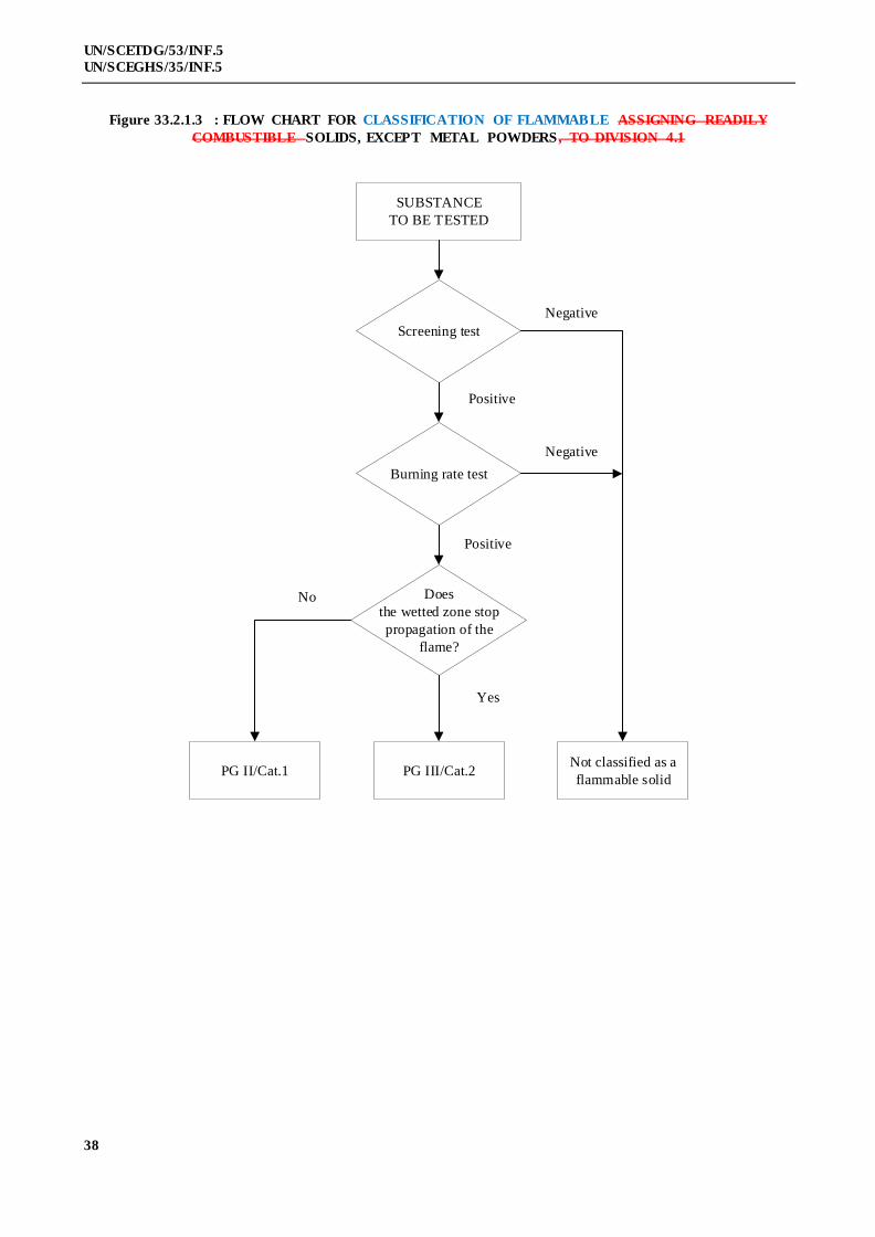
38
UN/SCETDG/53/INF.5
UN/SCEGHS/35/INF.5
Figure 33.2.1.3 : FLOW CHART FOR CLASSIFICATION OF FLAMMABLE ASSIGNING READILY
COMBUSTIBLE SOLIDS, EXCEPT METAL POWDERS, TO DIVISION 4.1
SUBSTANCE
TO BE TESTED
Screening test
Burning rate test
Does
the wetted zone stop
propagation of the
flame?
Not classified as a
flammable solidPG III/Cat.2PG II/Cat.1
Negative
Negative
Positive
Positive
Yes
No
39
UN/SCETDG/53/INF.5
UN/SCEGHS/35/INF.5
33.2.1.4 Test N.1: Test method for readily combustible flammable solids
33.2.1.4.1 Introduction
The ability of a substance to propagate combustion is tested by igniting it and determining the burning
time.
33.2.1.4.2 Apparatus and materials
A mould 250 mm long with a triangular cross-section of inner height 10 mm and width 20 mm is used
to form the train for the burning rate test. On both sides of the mould, in the longitudinal direction, two metal sheets are
mounted as lateral limitations which extend 2 mm beyond the upper edge of the triangular cross -section
(Figure 33.2.1.4.1). An impervious, non-combustible, low heat-conducting plate is used to support the sample train.
33.2.1.4.3 Procedure
33.2.1.4.3.1 Preliminary screening test
The substance in its commercial form, should be formed into an unbroken strip or powder train about
250 mm long by 20 mm wide by 10 mm high on a cool, impervious, low heat-conducting base plate. A hot flame
(minimum temperature 1 000 °C) from a gas burner (minimum diameter 5 mm) should be applied to one end of the
powder train until the powder ignites or for a maximum of 2 minutes (5 minutes for powders of metals or metal-alloys).
It should be noted whether combustion propagates along 200 mm of the train within the 2 minute test period (or
20 minutes for metal powders). If the substance does not ignite and propagate combustion either by burning with flame
or smouldering along 200 mm of the powder train within the 2 minute (or 20 minute) test period, then the substance
should not be classified as a flammable solid and no further testing is required. If the substance propagates burning of a
200 mm length of the powder train in less than 2 minutes or less than 20 minutes for metal powders, the full test
programme in 33.2.1.4.3.2 should be carried out.
33.2.1.4.3.2 Burning rate test
33.2.1.4.3.2.1 The powdered or granular substance, in its commercial form, should be loosely filled into the mould.
The mould is then dropped three times from a height of 20 mm onto a solid surface. The lateral limitations are then
removed and the impervious, non-combustible, low heat-conducting plate is placed on top of the mould, the apparatus
inverted and the mould removed. Pasty substances are spread on a non -combustible surface in the form of a rope
250 mm in length with a cross-section of about 100 mm2. In the case of a moisture sensitive substance, the test should
be carried out as quickly as possible after its removal from the container. The pile should be arranged across the draught
in a fume cupboard. The air speed should be sufficient to prevent fumes escaping into the laboratory and should not be
varied during the test. A draught screen may be erected around the apparatus.
33.2.1.4.3.2.2 For substances other than metal powders, 1 ml of a wetting solution should be added to the pile 30 -
40 mm beyond the 100 mm timing zone. Apply the wetting solution to the ridge drop by drop, ensuring the whole cross -
section of the pile is wetted without loss of liquid from the sides. The liquid should be applied over the shortest possible
length of the pile consistent with avoiding loss from the sides. With many substances, water rolls off the sides of the
pile, so the addition of wetting agents may be necessary. Wetting agents used should be free from combustible diluents
and the total active matter in the wetting solution should not exceed 1%. This liquid may be added to a hollow up to
3 mm deep and 5 mm in diameter in the top of the pile.
33.2.1.4.3.2.3 Any suitable ignition source such as a small flame or a hot wire of minimum temperature 1 000 °C is
used to ignite the pile at one end. When the pile has burned a distance of 80 mm, measure the rate of burning over the
next 100 mm. For substances other than metal powders, note whether or not the wetted zone stops propagation of the
flame for at least 4 minutes. The test should be performed six times using a clean cool plate each time, unless a positive
result is observed earlier.
33.2.1.4.4 Test criteria and method of assessing results
33.2.1.4.4.1 Powdered, granular or pasty substances should be classified in Division 4.1 as flammable solids when
the time of burning of one or more of the test runs, in accordance with the test method described in 33.2.1.3.4.2, is less
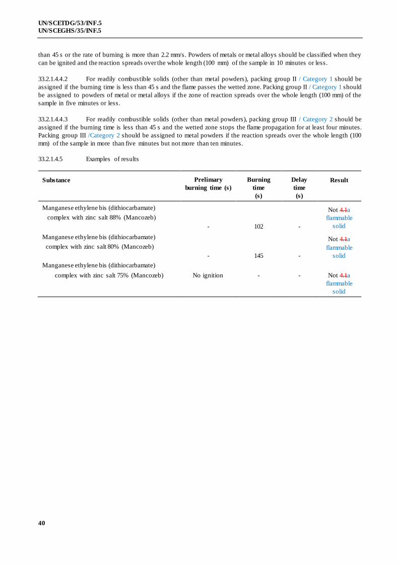
40
UN/SCETDG/53/INF.5
UN/SCEGHS/35/INF.5
than 45 s or the rate of burning is more than 2.2 mm/s. Powders of metals or metal alloys should be classified when they
can be ignited and the reaction spreads over the whole length (100 mm) of the sample in 10 minutes or less.
33.2.1.4.4.2 For readily combustible solids (other than metal powders), packing group II / Category 1 should be
assigned if the burning time is less than 45 s and the flame passes the wetted zone. Packing group II / Category 1 should
be assigned to powders of metal or metal alloys if the zone of reaction spreads over the whole length (100 mm) of the
sample in five minutes or less.
33.2.1.4.4.3 For readily combustible solids (other than metal powders), packing group III / Category 2 should be
assigned if the burning time is less than 45 s and the wetted zone stops the flame propagation for at least four minutes.
Packing group III /Category 2 should be assigned to metal powders if the reaction spreads over the whole length (100
mm) of the sample in more than five minutes but not more than ten minutes.
33.2.1.4.5 Examples of results
Substance Prelimary
burning time (s)
Burning
time
(s)
Delay
time
(s)
Result
Manganese ethylene bis (dithiocarbamate)
complex with zinc salt 88% (Mancozeb)
- 102 -
Not 4.1a
flammable
solid
Manganese ethylene bis (dithiocarbamate)
complex with zinc salt 80% (Mancozeb)
- 145 -
Not 4.1a
flammable
solid
Manganese ethylene bis (dithiocarbamate)
complex with zinc salt 75% (Mancozeb)
No ignition
-
-
Not 4.1a
flammable
solid
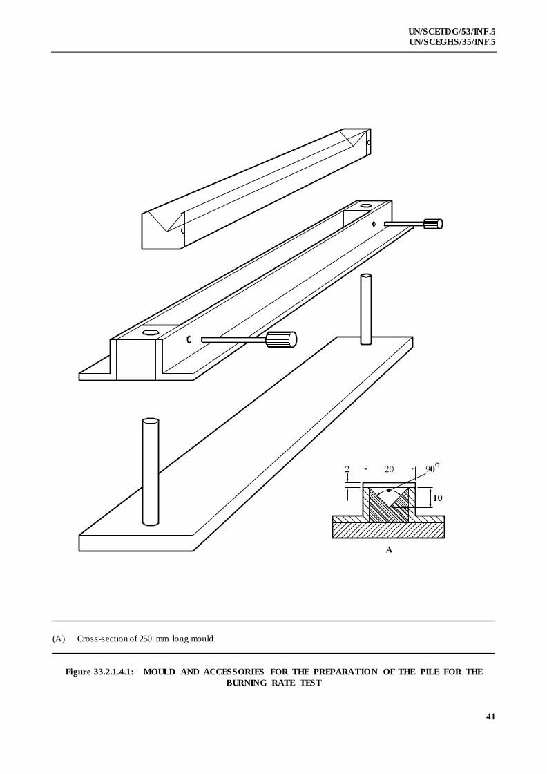
41
UN/SCETDG/53/INF.5
UN/SCEGHS/35/INF.5
(A) Cross-section of 250 mm long mould
Figure 33.2.1.4.1: MOULD AND ACCESSORIES FOR THE PREPARATION OF THE PILE FOR THE
BURNING RATE TEST
42
UN/SCETDG/53/INF.5
UN/SCEGHS/35/INF.5
33.2.2 (Reserved)
33.2.3 Solid desensitized explosives of Division 4.1
33.2.3.1 This sub-section presents the United Nations Model Regulations scheme for the classification of
desensitized explosives as flammable solids of of Division 4.1 (see sub-section 2.4.2.4 of the Model Regulations and
note 2 to paragraph 2.1.1.1 of the GHS). Solid desensitized explosives are substances which are wetted with water or
alcohols or are diluted with other substances to form a homogeneous solid mixture in order to suppress their explosive
properties.
33.2.3.2 New products which are thermally stable and have, or are suspected of having, explosive properties
should first be considered for Class 1 and the Class 1 acceptance procedure and, if necessary, the assignment procedure
applied.
33.2.3.32 Where a substance meets the criteria for classification as an explosiuve is assigned to Class 1 but is
diluted to be exempted from Class 1 this class by test series 6 (see section 16), this diluted substance, when meeting the
classification criteria or definition for another hazard class or division, should be classified in that class or division at
the highest concentration which exempts it from the class of explosivesClass 1. When sufficiently diluted, such
substances may be deemed to be non-dangerous for some regulatory purposes (e.g. transport) (see also paragraph
2.1.3.56.3 of the Model Regulations).
33.2.3.4 The classification scheme of solid desensitized explosives for supply and use (including storage)
according to the Globally Harmonized System of Classification and Labelling of Chemicals (GHS) is referred to given
in section 51.
33.3 Division 4.2 Pyrophoric and Self-Heating Substances
33.3.1 Substances liable to spontaneous combustion
33.3.1.1 Purpose
33.3.1.1.1 This sub-section presents the United Nations scheme for the classification of substances liable to
spontaneous combustion of Division 4.2 i.e. pyrophoric solids and liquids and self-heating substances (see section 2.4.3
of the Model Regulations and Chapters 2.9, 2.10 and 2.11 of the GHS). The text should be used in conjunction with the
classification principles given in these referecnes sub-sections 2.4.3.2 and 2.4.3.3 of the Model Regulations and the test
prescriptions given here in 33.3.1.4 to 33.3.1.6.
33.3.1.1.2 The test procedures are intended to identify two types of substances with spontaneous combustion
properties:
(a) Liquid or solid sSubstances, including mixtures and solutions (liquid or solid) which, even in small
quantities, ignite within five minutes of coming in contact with air. These substances are the most liable to
spontaneous combustion and are called pyrophoric substances;
(b) Other substances which, in contact with air and without an energy supply, are liable to self-
heating. These substances They will ignite only when in large amounts (kilograms) and after
long periods of time (hours or days) and are called self-heating substances.
33.3.1.1.3 The test procedures outlined here adequately assess the relative hazard of substances liable to
spontaneous combustion so that an appropriate classification for transport can be made.
33.3.1.2 Scope
33.3.1.2.1 Products offered for transport should be subjected to the classification procedures as set out in sub -
sections 2.4.3.2 and 2.4.3.3 of the Model Regulations, unless it is impracticable (e.g. because of the physical properties)
to perform the tests. The classification procedure should be undertaken before a product is offered for transport.

43
UN/SCETDG/53/INF.5
UN/SCEGHS/35/INF.5
33.3.1.3 Classification procedure for substances liable to spontaneous combustion
33.3.1.3.1 Pyrophoric solids
A test is performed to determine if a solid ignites within five minutes of coming in contact with air.
The recommended test method is given here, in 33.3.1.4. Whether a substance is a pyrophoric solid of Division 4.2 is
decided on the basis of the test result. Packing group I /Category 1 is assigned to all pyrophoric solids.
33.3.1.3.2 Pyrophoric liquids
A test is performed to determine if a liquid ignites when added to an inert carrier and exposed to air
for five minutes. If no ignition occurs then the second part of the test is performed to determine if it chars or ignites a
filter paper. The recommended test method is given here in 33.3.1.5. Whether a substance is a pyrophoric liquid of
Division 4.2 is decided on the basis of the test result. Packing group I/ Category 1 is assigned to all pyrophoric liquids.
33.3.1.3.3 Self-heating substances
33.3.1.3.3.1 Tests are performed to determine if substances in a 25 mm or 100 mm sample cube, at test
temperatures of 100 °C, 120 °C or 140 °C, undergo spontaneous ignition or dangerous self-heating, which is indicated
by a 60 °C rise in temperature over the oven temperature within 24 hours. The classification scheme is illustrated in
Figure 33.3.1.3.3.1. These criteria are based on the self-ignition temperature of charcoal, which is 50 °C for a sample
cube of 27 m3. Substances with a temperature of spontaneous combustion higher than 50 °C for a volume of 27 m3
should not be classified as a self-heating substanceassigned to Division 4.2. Substances with a spontaneous ignition
temperature higher than 50 °C for a volume of 450 litres should not beassigned to packing group II / Category 1of
Division 4.2. The recommended test method is given here in 33.3.1.6.
33.3.1.3.3.2 If dangerous self-heating does not occur with the substance in a 100 mm sample cube at 140 °C then
the substance is not a self-heating substance of Division 4.2.
33.3.1.3.3.3 If dangerous self-heating occurs with the substance in a 100 mm sample cube at 140 °C then a test
with the substance in a 25 mm sample cube should be performed at 140 °C to determine if it should be assigned to
packing group II / Category 1.
33.3.1.3.3.4 If dangerous self-heating occurs at 140 °C with the substance in a 100 mm sample cube, but not a
25 mm sample cube, then a test with the substance in a 100 mm sample cube should be performed:
(a) At 120 °C if it is to be transported contained in packages of not more than 3 m3 volume; or
(b) At 100 °C if the substance is to be transported contained in packages of not more than
450 litres volume.
Whether packing group III / Category 2 of Division 4.2 is assigned or the substance is not a self-heating substance of
Division 4.2, in the packaging to be used, is decided on the basis of the tes t results.
33.3.1.3.3.5 Self-reactive substances type G which give a positive result with this test method may be classified in
Division 4.2 as self-heating substances (see 20.2.6).Note: pending proposals for correction from CEFIC.
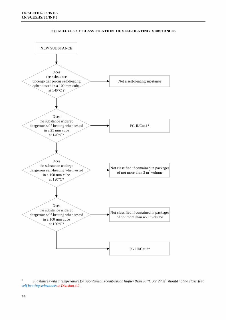
44
UN/SCETDG/53/INF.5
UN/SCEGHS/35/INF.5
Figure 33.3.1.3.3.1: CLASSIFICATION OF SELF-HEATING SUBSTANCES
NEW SUBSTANCE
Does
the substance
undergo dangerous self-heating
when tested in a 100 mm cube
at 140°C ?
Does
the substance undergo
dangerous self-heating when tested
in a 100 mm cube
at 120°C?
Does
the substance undergo
dangerous self-heating when tested
in a 100 mm cube
at 100°C?
PG III/Cat.2*
Not classified if contained in packages
of not more than 450 l volume
Not classified if contained in packages
of not more than 3 m3 volume
Not a self-heating substance
PG II/Cat.1*
Does
the substance undergo
dangerous self-heating when tested
in a 25 mm cube
at 140°C?
* Substances with a temperature for spontaneous combustion higher than 50 °C for 27 m3 should not be classi fied
self-heating substancesin Division 4.2.
45
UN/SCETDG/53/INF.5
UN/SCEGHS/35/INF.5
33.3.1.4 Test N.2: Test method for pyrophoric solids
33.3.1.4.1 Introduction
The ability of a solid to ignite on contact with air is tested by exposure to air and determining the time
to ignition.
33.3.1.4.2 Apparatus and materials
No special laboratory equipment is required.
33.3.1.4.3 Procedure
One to two ml of the powdery substance to be tested should be poured from about 1 m height onto a
non-combustible surface and it is observed whether the substance ignites during dropping or within 5 minutes of
settling. This procedure should be performed six times unless a positive result is obtained earlier.
33.3.1.4.4 Test criteria and method of assessing results
If the sample ignites in one of the tests, the substance should be considered pyrophoric and should be
classified as a pyrophoric solid of in packing group I / Category 1 of Division 4.2.
33.3.1.4.5 Examples of results
Substance Time to ignition (s) Result
Manganese ethylene bis (dithiocarbamate)
complex with zinc salt 88% (Mancozeb) No ignition within 5 minutes
Not a pyrophoric
solidPG I of 4.2
Manganese ethylene bis (dithiocarbamate)
complex with zinc salt 80% (Mancozeb) No ignition within 5 minutes
Not a pyrophoric
solidPG I of 4.2
Manganese ethylene bis (dithiocarbamate)
complex with zinc salt 75% (Mancozeb) No ignition within 5 minutes
Not a pyrophoric
solidPG I of 4.2
33.3.1.5 Test N.3: Test method for pyrophoric liquids
33.3.1.5.1 Introduction
The ability of a liquid to ignite when added to an inert carrier and exposed to air, or to char or ignite a
filter paper on contact with air, is determined.
33.3.1.5.2 Apparatus and materials
A porcelain cup of about 100 mm diameter and some diatomaceous earth or silica gel is required for
the first part of the test, and small pore size filter paper for the second part.
33.3.1.5.3 Procedure
33.3.1.5.3.1 A porcelain cup of about 100 mm diameter should be filled with diatomaceous earth or silica gel at
room temperature to a height of about 5 mm. Approximately 5 ml of the liquid to be tested should be poured into the
prepared porcelain cup and it is observed if the substance ignites within 5 minutes. This procedure should be performed
six times unless a positive result is obtained earlier. If a negative result is obtained then the procedure in 33.3.1.5.3.2
should be followed.
33.3.1.5.3.2 A 0.5 ml test sample should be delivered from a syringe to an indented dry filter paper. The test
should be conducted at 25 ± 2 °C and a relative humidity of 50 ± 5%. Observations are made to see if ignition or

46
UN/SCETDG/53/INF.5
UN/SCEGHS/35/INF.5
charring occurs on the filter paper within five minutes of addition of the liquid. This procedure should be performed
three times using fresh filter paper each time unless a positive result is obtained earlier.
33.3.1.5.4 Test criteria and method of assessing results
If the liquid ignites in the first part of the test, or if it ignites or chars the filter paper, it should be
considered to be pyrophoric and should be classified as a p;yrophoric liquid of in packing group I / Category 1 of
Division 4.2.
33.3.1.5.5 Examples of results
Substance Effect of
exposure to air
Effect
on filter paper
Result
Diethyl aluminium chloride/isopentane (10/90)
No ignition No charring
Not a
pyrophoric
liquid 4.2
Diethyl aluminium chloride/isopentane (15/85)
No ignition Charring
pyrophoric
liquid 4.2
Diethyl aluminium chloride/isopentane (95/5)
No ignition Charring
pyrophoric
liquid 4.2
Triethyl aluminium/heptane (10/90)
No ignition No charring
Not a
pyrophoric
liquid 4.2
Triethyl aluminium/heptane (15/85)
No ignition Charring
pyrophoric
liquid 4.2
Triethyl aluminium/heptane (95/5)
No ignition Charring
pyrophoric
liquid 4.2

47
UN/SCETDG/53/INF.5
UN/SCEGHS/35/INF.5
33.3.1.6 Test N.4: Test method for self-heating substances
33.3.1.6.1 Introduction
The ability of a substance to undergo oxidative self-heating is determined by exposure of it to air at
temperatures of 100 °C, 120 °C or 140 °C in a 25 mm or 100 mm wire mesh cube.
33.3.1.6.2 Apparatus and materials
The following apparatus is required:
a) a hot-air circulating type of oven with an inner volume of more than 9 litres and capable of
controlling the internal temperature at 100 °C, 120 °C or 140 °C ± 2 °C;
b) cubic sample containers of 25 mm and 100 mm side, made of stainless steel net with a mesh
opening of 0.05 mm, with their top surface open; and
c) Chromel-Alumel thermocouples of 0.3 mm diameter; one placed in the centre of the sample
and another between the sample container and the oven wall.
Each sample container should be housed in a cubic container cover made from a stainless steel net with a mesh opening
of 0.60 mm, and slightly larger than the sample container. In order to avoid the effect of air circulation, this cover is
installed in a second stainless steel cage, made from a net with a mesh size of 0.595 mm and 150 × 150 × 250 mm in
size.
33.3.1.6.3 Procedure
The sample, powder or granular, in its commercial form, should be filled to the brim of the sample
container and the container tapped several times. If the sample set tles, more is added. If the sample is heaped it should
be levelled to the brim. The container is housed in the cover and hung at the centre of the oven. The oven temperature
should be raised to 140 °C and kept there for 24 hours. The temperature of the sample and of the oven should be
recorded continuously. The first test1 may be conducted with a 100 mm cube sample. A positive result is obtained if
spontaneous ignition occurs or if the temperature of the sample exceeds the oven temperature by 60 °C. If a negative
result is obtained, no further test is necessary. If a positive result is obtained, a second test should be conducted at
140 °C with a 25 mm cube sample to determine whether or not packing group II / Category 1 should be assigned. If a
positive result is obtained at 140 °C with the substance in a 100 mm sample cube, but not a 25 mm sample cube, then an
additional test with the substance in a 100 mm sample cube should be performed:
(a) At 120 °C if the substance is to be transported contained in packagings of more than 450 litre
volume but not more than 3 m3 volume; or
(b) At 100 °C if the substance is to be transported contained in packagings of not more
than 450 litres volume.
33.3.1.6.4 Test criteria and method of assessing results
33.3.1.6.4.1 A positive result is obtained if spontaneous ignition occurs or if the temperature of the sample exceeds
the oven temperature by 60 °C during the 24 hour testing time. Otherwise, the result is considered negative.
1 The tests may be performed in any order. For example, if it is expected that a positive result will be obtained
using a 25 mm cube sample then, for safety and environmental protection, the first test may be performed with a 25 mm
cube sample. If a positive result is obtained with a 25 mm cube sample then a test with a 100 mm cube sample is not
necessary.
48
UN/SCETDG/53/INF.5
UN/SCEGHS/35/INF.5
33.3.1.6.4.2 A substance should not be classified as a self-heating substance in Division 4.2 if:
(a) A negative result is obtained in a test using a 100 mm cube sample at 140 °C;
(b) A positive result is obtained in a test using a 100 mm sample cube at 140 °C and a negative
result is obtained in a test using a 25 mm cube sample at 140 °C, a negative result is obtained
in a test using a 100 mm cube sample at 120 °C and the substance is to be transported
contained in packages with a volume not more than 3 m3;
(c) A positive result is obtained in a test using a 100 mm sample cube at 140 °C and a negative
result is obtained in a test using a 25 mm cube sample at 140 °C, a negative result is obtained
in a test using a 100 mm cube sample at 100 °C and the substance is to be transported
contained in packages with a volume not more than 450 litres.
33.3.1.6.4.3 Packing group II / Category 1 should be assigned to self-heating substances which give a positive
result in a test using a 25 mm sample cube at 140 °C.
33.3.1.6.4.4 Packing group III / Category 2 should be assigned to self-heating substances if:
(a) A positive result is obtained in a test using a 100 mm sample cube at 140 °C and a negative
result is obtained in a test using a 25 mm cube sample at 140 °C and the substance is to be
transported contained in packages with a volume of more than 3 m3;
(b) A positive result is obtained in a test using a 100 mm sample cube at 140 °C and a negative
result is obtained in a test using a 25 mm cube sample at 140 °C, a positive result is obtained in
a test using a 100 mm cube sample at 120 °C and the substance is to be transported contained
in packages with a volume of more than 450 litres;
(c) A positive result is obtained in a test using a 100 mm sample cube at 140 °C and a negative
result is obtained in a test using a 25 mm cube sample at 140 °C and a positive result is
obtained in a test using a 100 mm cube sample at 100 °C.

49
UN/SCETDG/53/INF.5
UN/SCEGHS/35/INF.5
33.3.1.6.5 Examples of results
Substance Oven
temperature
(°C)
Cube size
(mm)
Maximum
temperature
reached (°C)
Result
Cobalt/molybdenum catalyst
granules
140
140
100
25
>200
181
P.G. III of 4.2self-
heating PG III/Cat
2 a
Manganese ethylene bis
(dithiocarbamate) 80% (Maneb)
140
25
> 200
P.G. III of 4.2self-
heating PG II/Cat 1
Manganese ethylene bis
(dithiocarbamate) complex
with zinc salt 75% (Mancozeb)
140
25
> 200
P.G. III of 4.2self-
heating PG II/Cat 1
Nickel catalyst granules
with 70% hydrogenated oil
140
100
140
Not self-heating 4.2
Nickel catalyst granules
with 50% white oil
140
140
100
25
> 200
140
P.G. III of 4.2self-
heating PG III/Cat
2 a
Nickel/molybdenum catalyst
granules (spent)
140
140
100
25
> 200
150
P.G. III of 4.2self-
heating PG III/Cat
2 a
Nickel/molybdenum catalyst
granules (passivated)
140
100
161
Not self-heating 4.2
Nickel/vanadium catalyst
Granules
140
25
> 200
P.G. III of 4.2self-
heating PG II/Cat 1
a Not tested at 100 °C or 120 °C.

50
UN/SCETDG/53/INF.5
UN/SCEGHS/35/INF.5
33.4 Division 4.3
33.4.1 Substances which in contact with water emit flammable gases
33.4.1.1 Purpose
33.4.1.1.1 This section of the Manual presents the United Nations scheme for the classification of substances of
Division 4.3 which, in contact with water, emit flammable gases (see section 2.4.4 of the Model Regulations and
Chapter 2.12 of the GHS). The text should be used in conjunction with the classification principles given in sub-
sections 2.4.4.2 and 2.4.4.3 of the Model Regulations these references, together with the test prescription given here
in 33.4.1.4.
33.4.1.1.2 The test procedure is intended to determine whether the reaction of a substance with water leads to the
development of a dangerous amount of gases which may be flammable.
33.4.1.1.3 The test procedures outlined here adequately assess the relative hazard of substances liable to emit
flammable gases on contact with water (sometimes referred to as water reactive substances in the Model Regulations)
so that an appropriate classification for transport can be made.
33.4.1.2 Scope
33.4.1.2.1 New products offered for transport should be subjected to the classification procedures as set out in
sub-sections 2.4.4.2 and 2.4.4.3 of the Model Regulations. The classification procedure should be undertaken before a
new product is offered for transport.
33.4.1.3 Classification procedure for substances which in contact with water emit flammable gases
33.4.1.3.1 The test method can be applied to solid and liquid substances. In case a pyrophoric substance is tested,
the test should be executed under nitrogen atmosphere. The substance should be tested in its commercial form at
ambient temperate (20 °C) by bringing it into contact with water. If during any stage of the test the gas emitted ignites
then no further testing is necessary and the substance should be classified as a substance which, in contact with water,
emits flammable gases assigned to Division 4.3. If spontaneous ignition of the emitted gas does not occur then the final
stage of the test should be performed to determine the rate of emission of flammable gas. The recommended test
method, with possible results, is given here in 33.4.1.4. Whether a substance is a water-reactive substance of Division
4.3 and, if so, whether packing group I / Category 1, II / 2 or III / 3 should be assigned is decided on the basis of the test
result.
33.4.1.4 Test N.5: Test method for substances which in contact with water emit flammable gases
33.4.1.4.1 Introduction
The ability of a substance to emit flammable gases on contact with water is tested by bringing it into
contact with water under a variety of conditions.
33.4.1.4.2 Apparatus and materials
No special laboratory apparatus is required.
33.4.1.4.3 Procedure
33.4.1.4.3.1 The substance should be tested according to the procedures described below; if spontaneous ignition
occurs at any stage then no further testing is necessary. If it is known that the substance does not react violently with
water then proceed to 33.4.1.4.3.5.
33.4.1.4.3.2 A small quantity (approximately 2 mm diameter) of the test substance should be placed in a trough of
distilled water at 20 °C. It is noted:
(a) Whether any gas is evolved; and
51
UN/SCETDG/53/INF.5
UN/SCEGHS/35/INF.5
(b) If spontaneous ignition of the gas occurs.
33.4.1.4.3.3 A small quantity of the test substance (approximately 2 mm diameter) should be placed on the centre
of a filter paper which is floated flat on the surface of distilled water at 20 °C in a suitable vessel, e.g. a 100 mm
diameter evaporating dish. The filter paper is to keep the substance in one place, under which condition the likelihood
of spontaneous ignition of any gas is greatest. It is noted:
(a) Whether any gas is evolved; and
(b) If spontaneous ignition of the gas occurs.
33.4.1.4.3.4 The test substance should be made into a pile approximately 20 mm high and 30 mm diameter with a
hollow in the top. A few drops of water are added to the hollow. It is noted whether:
(a) Any gas is evolved; and
(b) If spontaneous ignition of the gas occurs.
33.4.1.4.3.5 For solids, the package should be inspected for any particles of less than 500 μm diameter. If that
powder constitutes more than 1% (mass) of the total, or if the substance is friab le, then the whole of the sample should
be ground to a powder before testing to allow for a reduction in particle size during handling and transport. Otherwise,
as for liquids, the substance should be tested in its commercial state. This test should be performed three times at
ambient temperature (20 °C) and atmospheric pressure. Water is put into the dropping funnel and enough of the
substance (up to a maximum mass of 25 g) to produce between 100 ml and 250 ml of gas is weighed and placed in a
conical flask. The tap of the dropping funnel is opened to let the water into the conical flask and a stop watch is started.
The volume of gas evolved is measured by any suitable means. The time taken for all the gas to be evolved is noted and
where possible, intermediate readings are taken. The rate of evolution of gas is calculated over 7 hours at 1 hour
intervals. If the rate of evolution is erratic or is increasing after 7 hours, the measuring time should be extended to a
maximum time of 5 days. The five day test may be stopped if the rate of evolution becomes steady or continually
decreases and sufficient data has been established to assign a packing group / category to the substance or to determine
that the substance should not be classified in Division 4.3this hazard class. If the chemical identity of the gas is
unknown, the gas should be tested for flammability.
33.4.1.4.4 Test criteria and method of assessing results
33.4.1.4.4.1 A substance should be classified in Division 4.3this hazard class if:
(a) Spontaneous ignition takes place in any step of the test procedure; or
(b) There is an evolution of a flammable gas at a rate greater than 1 litre per kilogram of the
substance per hour.
33.4.1.4.4.2 Packing group I / Category 1 should be assigned to any substance which reacts vigorously with water
at ambient temperatures and generally demonstrates a tendency for the gas produced to ignite spontaneously, or which
reacts readily with water at ambient temperatures such that the rate of evolution of flammable gas is equal to or greater
than 10 litres per kilogram of substance over any one minute period.
33.4.1.4.4.3 Packing group II / Categort 2 should be assigned to any substance which reacts readily with water at
ambient temperatures such that the maximum rate of evolution of flammable gas is equal to or greater than 20 litres per
kilogram of substance per hour, and which does not meet the criteria for packing group I / category 1.
33.4.1.4.4.4 Packing group III / Category 3 should be assigned to any substance which reacts slowly with water at
ambient temperatures such that the maximum rate of evolution of flammable gas is greater than 1 litre per kilogram of
substance per hour, and which does not meet the criteria for packing groups I or II / categories 1 or 2.

52
UN/SCETDG/53/INF.5
UN/SCEGHS/35/INF.5
33.4.1.4.5 Examples of results
Substance Rate of gas
emission
(litre/kg.h)
Spontaneous
ignition of gas
(yes/no)
Result
Manganese ethylene bis (dithiocarbamate)
complex with zinc salt 88% (Mancozeb)
0 Not applicable Not
4.3classif
ied in
this
hazard
class
53
UN/SCETDG/53/INF.5
UN/SCEGHS/35/INF.5
SECTION 34
CLASSIFICATION PROCEDURES, TEST METHODS AND
CRITERIA RELATING TO OXIDIZING SOLIDS AND LIQUIDSSUBSTANCES
OF DIVISION 5.1
34.1 Purpose
34.1.1 This section presents the United Nations scheme for the classification of oxidizing solids and liquids
substances of Division 5.1 (see section 2.5.2 of the Model Regulations and Chapters 2.13 and 2.14 of the GHS). The
text should be used in conjunction with the classification principles given in these references paragraphs 2.5.2.2 and
2.5.2.3 of the Model Regulations and the test prescriptions given here in section 34.4.
34.2 Scope
34.2.1 New products offered for transport should be classified according to the criteriasubjected to the
classification procedures as set out in paragraphs 2.5.2.2.1 and 2.5.2.2.2 or 2.5.2.3.1 and 2.5.2.3.2 of the Model
Regulations unless it is impracticable (e.g. because of the physical properties) to perform the tests. Substances which
cannot be tested should be classified by analogy with existing entries. The classification procedure should be
undertaken before a new product is offered for transport.
34.3 Classification procedure
The test procedures outlined here adequately assess the relative hazard of oxidizing solids and
liquidssubstances so that an appropriate classification for transport can be made by the competent authority. In the event
of divergence between test results and known experience, judgement based on known experience should take
precedence over test results.
34.3.1 Oxidizing solids
A test is performed to determine the potential for a solid substance to increase the burning rate or
burning intensity of a combustible substance when the two are thoroughly mixed. The recommended test methods are
given here and in sub-section 2.5.2.2 of the Model Regulations. Whether a solid is an oxidizing substance of Division
5.1 and, if so, whether packing group I, II or III / Category 1, 2 or 3 should be assigned, is decided on the basis of the
test result. For transport, in case of solids representing more than one hazard characteristics (see also Precedence of
hazards characteristics in section 2.0.3 of the Model Regulations ). As the particle size has a significant effect on the
result, the particle size of the solidsubstance tested should be stated in the test report. By execption, solid ammonium
nitrate based fertilizers are not classified as oxidizing solids on the basis of results from tests O.1 or O.3, since the
hazardous properties are not sufficiently by the outcome of tests for oxidizing properties. Instead, such fertilizers are
classified on the basis of acquired experience and knowledge of their hazardous behaviour. They shall be classified in
accordance with the procedure set out in Section 39.
34.3.2 Oxidizing liquids
A test is performed to determine the potential for a liquid substance to increase the burning rate or
burning intensity of a combustible substance or for spontaneous ignition to occur when the two are thoroughly mixed.
The recommended test method given here measures the pressure rise time during combustion. Whether a liquid is an
oxidizing substance of Division 5.1 and, if so, whether packing group I, II or III / Category 1, 2 or 3 should be assigned,
is decided on the basis of the test result. For transport, in case of liquids representing more than one hazard
characteristics (see also Precedence of hazards characteristics in section 2.0.3 of the Model Regulations ).

54
UN/SCETDG/53/INF.5
UN/SCEGHS/35/INF.5
34.4 Test methods for oxidizing solids and liquidssubstances
34.4.1 Test O.1: Test for oxidizing solids
34.4.1.1 Introduction
This test method is designed to measure the potential for a solid substance to increase the burning rate
or burning intensity of a combustible substance when the two are thoroughly mixed. Tests are conducted on the
substance to be evaluated mixed with dry cellulose in mixing ratios of 1:1 and 4:1, by mass, of sample to cellulose. The
burning characteristics of the mixtures are compared with the standard 3:7 mixture, by mass, of potassium bromate to
cellulose. If the burning time is equal to or less than this standard mixture, the burning times should be compared with
those from the packing group I or II / category 1 or 2 reference standards, 3:2 and 2:3 ratios, by mass, of potassium
bromate to cellulose respectively.
34.4.1.2 Apparatus and materials
34.4.1.2.1 Technically pure potassium bromate is required as a reference substance. It should be sieved, but not
ground, and the fraction with nominal particle sizes in the range 0.15 to 0.30 mm used as the reference substance. The
reference substance is dried at 65 °C to constant mass (for a minimum of 12 hours) and kept in a desiccator (with
desiccant) until cool and required for use.
34.4.1.2.2 Dried white cellulose1, with a fibre mean diameter of approximately 25 µm, grain size less than 100
µm, apparent density of approximately 170 kg/m3 and pH value between 5 and 7, is used as the combustible material. It
is dried in a layer no more than 25 mm thick at 105 °C to constant mass (for a minimum of 4 hours) and kept in a
desiccator (with desiccant) until cool and required for use. The water content should be less than 0.5% by dry mass. If
necessary, the drying time should be prolonged to achieve this.
34.4.1.2.3 An ignition source is required comprising an inert metal wire (e.g. nickel/chromium) connected to an
electrical power source and with the following characteristics:
(a) Length = 30 ± 1 cm;
(b) Diameter = 0.6 ± 0.05 mm;
(c) Electrical resistance = 6.0 ± 0.5 Ω/m;
(d) Electrical power dissipated in the wire = 150 ± 7 W.
The wire should be shaped as in Figure 34.4.1.1.
34.4.1.2.4 A 60° glass funnel, sealed at the narrow end, with an internal diameter of 70 mm is required to form
the mixtures into a truncated conical pile with base diameter of 70 mm on a cool, impervious, low heat conducting
plate. A 150 mm by 150 mm plate with a thickness of 6 mm and a thermal conductivity (at a temperature of 0 °C) of
0.23 W.m-1.K-1 is suitable. Other plates with a similar conductivity may be used.
34.4.1.2.5 A fume cupboard or other kind of ventilated area is required in which there is some ventilation but
with an air stream velocity of 0.5 m/s or less. The fume extraction system should be suitable for the capture of toxic
fumes.
34.4.1.2.6 The substance, in the form in which it will be transported, should be inspected for any particles less
than 500 μm in diameter. If that powder constitutes more than 10% (mass) of the total, or if the substance is friable, then
the whole of the test sample should be ground to a powder before testing to allow for a reduction in particle size during
handling and transport.
1 Source reference available from the national contact for test details in France (see Appendix 4).
55
UN/SCETDG/53/INF.5
UN/SCEGHS/35/INF.5
34.4.1.3 Procedure
34.4.1.3.1 30.0 g ± 0.1 g mixtures of the reference substance and cellulose are prepared in the potassium bromate
to cellulose ratios of 3:7, 2:3 and 3:2, by mass. 30.0 g ± 0.1 g mixtures of the substance to be tested, in the particle size
in which it will be transported (seeas determined in paragraph 34.4.1.2.6), and cellulose are prepared in the oxidizer to
cellulose ratios of 4:1 and 1:1, by mass. Each mixture should be mixed mechanically as thoroughly as possible without
excessive stress. Each sample mixture should be made individually, used as soon as possible, and not taken from a
batch.
34.4.1.3.2 Using the conical funnel, the mixture should be formed into a truncated conical pile, with a base
diameter of 70 mm, covering the looped ignition wire resting on the low heat conducting plate. The plate should be
placed in a ventilated area and the test performed at atmospheric pressure with the ambient temperature at 20 °C ± 5 °C.
34.4.1.3.3 Power is applied to the ignition wire and is maintained for the duration of the test or for three minutes
if the mixture does not ignite and burn. The recorded burning time is taken from when the power is switched on to when
the main reaction (e.g. flame, incandescence or glowing combustion) ends. Intermittent reaction, such as sparking or
sputtering, after the main reaction should not be taken into account. If the heating wire breaks during the test then the
test should be repeated unless breaking of the wire clearly does not affect the result. The test should be performed five
times on the substance. Five tests should be performed with each reference mixture required to make the packing group
/ category assignment or to determine if the substance should not be classified as an oxidizing solid in Division 5.1.
34.4.1.4 Test criteria and method of assessing results
34.4.1.4.1 The results are assessed on the basis of:
(a) The comparison of the mean burning time with those of the reference mixtures; and
(b) Whether the mixture of substance and cellulose ignites and burns.
34.4.1.4.2 The test criteria for determining oxidizing properties of the substance are:
Packing group I / category 1: Any substance which, in the 4:1 or 1:1 sample-to-cellulose ratio (by mass) tested,
exhibits a mean burning time less than the mean burning time of a 3:2 mixture, by mass,
of potassium bromate and cellulose.
Packing group II / category 2: Any substance which, in the 4:1 or 1:1 sample-to-cellulose ratio (by mass) tested,
exhibits a mean burning time equal to or less than the mean burning time of a 2:3
mixture (by mass) of potassium bromate and cellulose; and which does not meet the
criteria for packing group I / category 1.
Packing group III / category 3: Any substance which, in the 4:1 or 1:1 sample-to-cellulose ratio (by mass) tested,
exhibits a mean burning time equal to are less than the mean burning time of a 3:7
mixture (by mass) of potassium bromate and cellulose; and which does not meet the
criteria for packing groups I and II / categories 1 and 2.
Not an oxidizing solid Division 5.1 Any substance which, in both the 4:1 and 1:1 sample-to-cellulose ratio (by mass)
tested, does not ignite and burn, or exhibits mean burning times greater than that of
a 3:7 mixture (by mass) of potassium bromate and cellulose.
For the assignment of precedence of hazards for transport purposes in the case of substances having other hazards, e.g.
toxicity or corrosivity, the requirements of section 2.0.3 of the Model Regulations should be met.
34.4.1.5 Examples of results
NOTE: The test results given should be used only as an illustration since the results obtained with a particular oxidizer
will depend on the particle size etc.

56
UN/SCETDG/53/INF.5
UN/SCEGHS/35/INF.5
Substance Mean burning times (s)
Results 4:1 1:1
Ammonium dichromate 55 189 PG III/cat. 3 a
Ammonium nitrate (crystalline) 161 74 PG III/cat. 3
Calcium nitrate (anhydrous) 10 25 PG II/cat. 2 b
Calcium nitrate (tetra hydrate) 268 142 Not an oxidizing solid 5.1
Ceric ammonium nitrate 10 36 PG II/cat. 2 c
Chromium trioxide 3 33 PG I/cat. 1 a
Cobalt nitrate (hexahydrate) 205 390 Not an oxidizing solid 5.1
Nickel nitrate 101 221 Not an oxidizing solid 5.1 b
Potassium nitrite 8 15 PG II/cat. 2
Potassium perchlorate 9 33 PG II/cat. 2
Potassium permanganate 17 51 PG II/cat. 2
Sodium chlorate 5 13 PG II/cat. 2
Sodium nitrite 15 22 PG II/cat. 2 b
Sodium nitrate 56 39 PG II/cat. 2 b
Strontium nitrate (anhydrous) 107 237 Not an oxidizing solid 5.1 b
Burning times for mixtures of reference substance to cellulose
3:7 Potassium bromate/cellulose 100 s
2:3 Potassium bromate/cellulose 54 s
3:2 Potassium bromate/cellulose 4 s
a Currently PG II / cat. 2 but borderline. b Currently PG III / cat. 3. c Not currently classified as an oxidizing solid.

57
UN/SCETDG/53/INF.5
UN/SCEGHS/35/INF.5
(A) Base of sample cone (70 mm diameter)
(B) Heating wire
(C) Low heat conducting plate
Figure 34.4.1.1: TEST PLATE AND IGNITION WIRE
58
UN/SCETDG/53/INF.5
UN/SCEGHS/35/INF.5
34.4.2 Test O.2: Test for oxidizing liquids
34.4.2.1 Introduction
This test method is designed to measure the potential for a liquid substance to increase the burning
rate or burning intensity of a combustible substance when the two are thoroughly mixed or to form a mixture which
spontaneously ignites. The liquid is mixed in a 1 to 1 ratio, by mass, with cellulose, the mixture heated in a pressure
vessel and the rate of pressure rise determined2.
34.4.2.2 Apparatus and materials
34.4.2.2.1 A pressure vessel, as used in the time/pressure test (see Part I, test 1 (c) (i)), is required. It consists of a
cylindrical steel pressure vessel 89 mm in length and 60 mm in external diameter (see Figure 34.4.2.1). Two flats are
machined on opposite sides (reducing the cross -section of the vessel to 50 mm) to facilitate holding whilst fitting up the
firing plug and vent plug. The vessel, which has a bore of 20 mm diameter is internally rebated at either end to a depth
of 19 mm and threaded to accept 1" British Standard Pipe (BSP). A pressure take-off, in the form of a side arm, is
screwed into the curved face of the pressure vessel 35 mm from one end and at 90° to the machined flats. The socket for
this is bored to a depth of 12 mm and threaded to accept the 1/2 " BSP thread on the end of the side-arm. If necessary,
an inert seal is fitted to ensure a gastight seal. The side-arm extends 55 mm beyond the pressure vessel body and has a
bore of 6 mm. The end of the side-arm is rebated and threaded to accept a diaphragm type pressure transducer. Any
pressure-measuring device may be used provided that it is not affected by the hot gases or the decomposition products
and is capable of responding to rates of pressure rise of 690-2 070 kPa in not more than 5 ms.
34.4.2.2.2 The end of the pressure vessel furthest from the side-arm is closed with a firing plug which is fitted
with two electrodes, one insulated from, and the other earthed to, the plug body. The other end of the pressure vessel is
closed by a bursting disc (bursting pressure approximately 2 200 kPa (320 psi)) held in place with a retaining plug
which has a 20 mm bore. If necessary, an inert seal is used with the firing plug to ensure a gas-tight fit. A support stand
(Figure 34.4.2.2) holds the assembly in the correct attitude during use. This comprises a mild steel base plate measuring
235 mm × 184 mm × 6 mm and a 185 mm length of square hollow section (S.-H.S.) 70 × 70 × 4 mm.
34.4.2.2.3 A section is cut from each of two opposite sides at one end of the length of S.H.S. so that a structure
having two flat sided legs surmounted by 86 mm length of intact box section results. The ends of these flat sides are cut
to an angle of 60° to the horizontal and welded to the base plate. A slot measuring 22 mm wide × 46 mm deep is
machined in one side of the upper end of the base section such that when the pressure vessel assembly is lowered, firing
plug end first, into the box section support, the side-arm is accommodated in the slot. A packing piece of steel 30 mm
wide and 6 mm thick is welded to the lower internal face of the box section to act as a spacer. Two 7 mm thumb screws,
tapped into the opposite face, serve to hold the pressure vessel firmly in place. Two 12 mm wide strips of 6 mm thick
steel, welded to the side pieces abutting the base of the box section, support the pressure vessel from beneath.
34.4.2.2.4 The ignition system consists of a 25 cm long Ni/Cr wire with a diameter 0.6 mm and a resistance of
3.85 ohm/m. The wire is wound, using a 5 mm diameter rod, in the shape of a coil and is attached to the firing plug
electrodes. The coil should have one of the configurations shown in Figure 34.4.2.3. The distance between the bottom
of the vessel and the underside of the ignition coil should be 20 mm. If the electrodes are not adjustable, the ends of the
ignition wire between the coil and the bottom of the vessel should be insulated by a ceramic sheath. The wire is heated
by a constant current power supply able to deliver at least 10 A.
34.4.2.2.5 Dried white cellulose3 with a fibre mean diameter of approximately 25 µm, grain size less than 100
µm, apparent density of approximately 170 kg/m3 and pH value between 5 and 7, is used as the combustible material.It
is dried in a layer not more than 25 mm thick at 105 °C for 4 hours and kept in a desiccator, with desiccant, until cool
and required for use. The water content of the dried cellulose should be less than 0.5% by dry mass. If necessary, the
drying time should be prolonged to achieve this.
2 In some cases, substances may generate a pressure rise (too high or too low), caused by chemical reactions not
characterising their oxidizing properties of the substance. In these cases, it may be necessary to repeat the test with an inert
substance, e.g. diatomite (kieselguhr), in place of the cellulose in order to clarify the nature of the reaction. 3 Source reference available from the national contact for test details in France (see Appendix 4).
59
UN/SCETDG/53/INF.5
UN/SCEGHS/35/INF.5
34.4.2.2.6 50% perchloric acid, 40% aqueous sodium chlorate solution and 65% aqueous nitric acid are required
as reference substances.
34.4.2.2.7 The concentration of the substance tested should be specified in the report. If saturated solutions are
tested, they should be prepared at 20 °C.
34.4.2.3 Procedure
34.4.2.3.1 The apparatus, assembled complete with pressure transducer and heating system but without the
bursting disc in position, is supported firing plug end down. 2.5 g of the liquid to be tested is mixed with 2.5 g of dried
cellulose in a glass beaker using a glass stirring rod. For safety, the mixing should be performed with a safety shield
between the operator and mixture. (If the mixture ignites during mixing or filling, no further testing is necessary.) The
mixture is added, in small portions with tapping, to the pressure vessel making sure that the mixture is packed around
the ignition coil and is in good contact with it . It is important that the coil is not distorted during the packing process.
The bursting disc is placed in position and the retaining plug is screwed in tightly. The charged vessel is transferred to
the firing support stand, bursting disc uppermost, which should be located in a suitable, armoured fume cupboard or
firing cell. The power supply is connected to the external terminals of the firing plug and 10 A applied. The time
between the start of mixing and switching the power on should be about 10 minutes.
34.4.2.3.2 The signal produced by the pressure transducer is recorded on a suitable system which allows both
evaluation and the generation of a permanent record of the time pressure profile obtained (e.g. a transient recorder
coupled to a chart recorder). The mixture is heated until the bursting disc ruptures or until at least 60 s has elapsed. If
the bursting disc does not rupture, the mixture should be allowed to cool before carefully dismantling the apparatus
and precautions taken to allow for any pressurisation. Five trials are performed with the mixture and each of the
reference substances. The time taken for the pressure rise from 690 kPa to 2 070 kPa above atmospheric is noted. The
mean time interval should be used for classification.
34.4.2.4 Test criteria and method of assessing results
34.4.2.4.1 The test results are assessed on the basis of:
(a) Whether the mixture of substance and cellulose spontaneously ignites; and
(b) The comparison of the mean time taken for the pressure to rise from 690 kPa to 2 070 kPa
gauge with those of the reference substances.
34.4.2.4.2 The test criteria for determining the oxidizing properties of the substance are:
Packing group I/category 1: - Any substance which, in the 1:1 mixture, by mass, of substance and cellulose tested,
spontaneously ignites; or
- The mean pressure rise time of a 1:1 mixture, by mass, of substance and cellulose is less
than that of a 1:1 mixture, by mass, of 50% perchloric acid and cellulose.
Packing group II/category 2: - Any substance which, in the 1:1 mixture, by mass, of substance and cellulose tested,
exhibits a mean pressure rise time less than or equal to the mean pressure rise time of a
1:1 mixture, by mass, of 40% aqueous sodium chlorate solution and cellulose; and
- The criteria for packing group I / category 1 are not met.
Packing group III/category 3: - Any substance which, in the 1:1 mixture, by mass, of substance and cellulose tested,
exhibits a mean pressure rise time less than or equal to the mean pres sure rise time of a
1:1 mixture, by mass, of 65% aqueous nitric acid and cellulose; and
- The criteria for packing groups I and II / categories 1 and 2 are not met.
Not and oxidizing liquid Division 5.1: - Any substance which, in the 1:1 mixture, by mass, of substance and
cellulose tested, exhibits a pressure rise of less than 2 070 kPa gauge; or
- Exhibits a mean pressure rise time greater than the mean pressure rise time of a 1:1
mixture, by mass, of 65% aqueous nitric acid and cellulose.
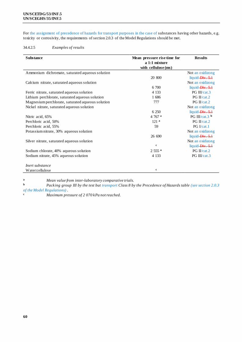
60
UN/SCETDG/53/INF.5
UN/SCEGHS/35/INF.5
For the assignment of precedence of hazards for transport purposes in the case of substances having other hazards, e.g.
toxicity or corrosivity, the requirements of section 2.0.3 of the Model Regulations should be met.
34.4.2.5 Examples of results
Substance Mean pressure rise time for
a 1:1 mixture
with cellulose (ms)
Results
Ammonium dichromate, saturated aqueous solution
20 800
Not an oxidizong
liquid Div. 5.1
Calcium nitrate, saturated aqueous solution
6 700
Not an oxidizong
liquid Div. 5.1
Ferric nitrate, saturated aqueous solution 4 133 PG III/cat.3
Lithium perchlorate, saturated aqueous solution 1 686 PG II/cat.2
Magnesium perchlorate, saturated aqueous solution 777 PG II/cat.2
Nickel nitrate, saturated aqueous solution
6 250
Not an oxidizong
liquid Div. 5.1
Nitric acid, 65% 4 767 a PG III/cat.3 b
Perchloric acid, 50% 121 a PG II/cat.2
Perchloric acid, 55% 59 PG I/cat.1
Potassium nitrate, 30% aqueous solution
26 690
Not an oxidizong
liquid Div. 5.1
Silver nitrate, saturated aqueous solution c
Not an oxidizong
liquid Div. 5.1
Sodium chlorate, 40% aqueous solution 2 555 a PG II/cat.2
Sodium nitrate, 45% aqueous solution 4 133 PG III/cat.3
Inert substance
Water:cellulose
c
a Mean value from inter-laboratory comparative trials. b Packing group III by the test but transport Class 8 by the Precedence of Hazards table (see section 2.0.3
of the Model Regulations) . c Maximum pressure of 2 070 kPa not reached.
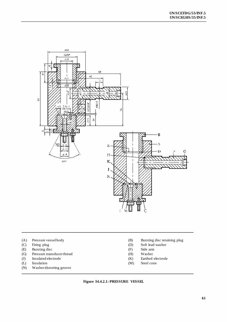
61
UN/SCETDG/53/INF.5
UN/SCEGHS/35/INF.5
(A) Pressure vessel body (B) Bursting disc retaining plug
(C) Firing plug (D) Soft lead washer
(E) Bursting disc (F) Side arm
(G) Pressure transducer thread (H) Washer
(J) Insulated electrode (K) Earthed electrode
(L) Insulation (M) Steel cone
(N) Washer distorting groove
Figure 34.4.2.1: PRESSURE VESSEL
60°
60°

62
UN/SCETDG/53/INF.5
UN/SCEGHS/35/INF.5
Figure 34.4.2.2: SUPPORT STAND
60°

63
UN/SCETDG/53/INF.5
UN/SCEGHS/35/INF.5
NOTE: Either of these configurations may be used.
(A) Ignition coil
(B) Insulation
(C) Electrodes
(D) Firing plug
Figure 34.4.2.3: IGNITION SYSTEM

64
UN/SCETDG/53/INF.5
UN/SCEGHS/35/INF.5
34.4.3 Test O.3: Gravimetric test for oxidizing solids
34.4.3.1 Introduction
This test method is designed to measure the potential for a solid substance to increase the burning rate
or burning intensity of a combustible substance when the two are thoroughly mixed. Tests are conducted on the test
substance to be evaluated mixed with dry cellulose in mixing ratios of 1:1 and 4:1, by mass. The burning rates of these
mixtures are compared to the reference mixture of calcium peroxide and cellulose in a mixing ratio of 1:2, by mass. The
mass loss of the mixtures during combustion is determined using a balance connected to a suitable data recording
system, and is recorded as a function of time. If the burning rate (g/s) is equal to or greater than the burning rate of the
reference mixture for Packing Group III / category 3, it is then compared to the burning rate of the reference mixtures
for Packing Group I or II / categories 1 or 2 (see table in 34.4.3.4).
The GHS also refers to this test for classification within the hazard class Oxidizing Solids. For the
ranking according to oxidizing power, the GHS uses three categories which correspond exactly to the Packing Groups
used within the transport of dangerous goods regime. The GHS categories 1, 2 and 3 thus correspond directly t o
Packing Groups I, II and III, respectively.
It is useful to have preliminary information on any potentially explosive properties of the substance
before performing the test, screening procedures can be found in Appendix 6. This test is not applicable for substances
which are explosive or flammable and also not for organic peroxides.
34.4.3.2 Materials
34.4.3.2.1 Technically pure, finely powdered calcium peroxide with a concentration of 75% ± 0.5% is required as
the reference oxidizer. The concentration of impurities such as chlorides or compounds which generate water during
combustion should be low, as they may impact on the burning behavior of the reference piles. Calcium peroxide
meeting the specification below can be used without further pretreatment.4
CaO2: 75% ± 0.5%
Ca(OH)2: 20% to 25%
CaCO3: 0% to 5%
Chloride: max 500 ppm
Particle size: min 99% < 75 µm, and thereof
min 50% < 20 µm
34.4.3.2.2 Dried white cellulose5 with a fibre mean diameter of approximately 25 µm, grain size less than 100 µm,
apparent density of approximately 170 kg/m3 and pH value between 5 and 7, is used as the combustible material. It is
dried to constant mass (for a minimum of 4 hours), in a layer no more than 25 mm thick, at 105 °C and kept in a
desiccator (with desiccant) until cool and required for use. The water content should be less than 0.5% by dry mass. If
necessary, the drying time should be prolonged to achieve this. The bulk density o f the cellulose used for the test should
be such (sufficiently high) that the test mixture for Packing Group III / category 3 (30.0 g ± 0.1 g) can be completely
accommodated in the conical funnel.
34.4.3.2.3 The test-substance, in the form in which it will be presented, should be inspected for any particles less
than 500 µm in diameter. If that powder constitutes more than 10% (by mass) of the total, or if the substance is friable,
then the whole of the test sample should be ground to a powder of less than 500 µm before testing, to allow for a
reduction in particle size during handling and transport. Because the particle size influences the oxidizing properties of
a substance, a coarse oxidizer may be classified as Packing Group III / category 3, while a finer grade of the same
material may show a faster burning rate and may result in different GHS classifications and assigned transport Packing
Groups for different forms of the same material.
4 Obtainable from the national contact for test details in Germany (see Appendix 4). 5 Source reference available from the national contact for test details in France (see Appendix 4).

65
UN/SCETDG/53/INF.5
UN/SCEGHS/35/INF.5
34.4.3.3 Apparatus6
34.4.3.3.1 An appropriate balance is required, with a suitable range, accuracy and data transfer capability, equipped
with an interface (e.g. USB or RS232) to allow data acquisition. The required data (time, mass) are recorded, preferably
with a frequency of at least 5 data per second. Any suitable s oftware capable of recording the output of the balance may
be used. It is recommended to check the time frequency of the software and the monitoring of time by a stopwatch
maybe useful.
34.4.3.3.2 An ignition source is required, comprising an inert metal wire connected to an electrical power source
capable of maintaining the power dissipation specified below. The electrical resistance depends on the wire material. It
is recommended to use Nickel/Chromium or AluChrom wire as follows:
(a) Length = 30 cm ± 1 cm;
(b) Diameter below 1 mm;
(c) Electrical power dissipated in the wire = 150 W ± 7 W.
The wire should be shaped as shown in figure 34.4.3.2. It is very important that the power connection
to the heating wire is flexible enough to avoid any influence on the proper operation of the balance.
34.4.3.3.3 A 60° funnel, with an internal diameter of 70 mm and sealed at the narrow end, is required to form the
mixtures into a truncated conical pile with a base diameter of 70 mm on a cool, impervious, low heat conducting plate.
34.4.3.3.4 An insulating test plate is needed to avoid loss of energy by thermal conduction. A 150 mm by 150 mm
test plate with a thickness of at least 6 mm and a thermal conductivity at 0 °C of 0.23 W*m-1*K-1 or less is suitable.
Other plates with a similar conductivity may be used. In order to increase the lifetime of the test plate, it may be
covered with a thin ceramic sheet with the same low thermal conductivity.
34.4.3.3.5 A fume cupboard or other suitably ventilated area is required but the air stream velocity should be 0.5 m/s
or less. The fume extraction system should be capable of capturing all toxic fumes.
34.4.3.3.6 To construct the support for the burning trial on the balance a base plate of solid material (steel or other
suitable material), a positioning plate of fire resistant material (the same material as test -plate is recommended) and
guide bars are required.
34.4.3.3.7 The air stream of the ventilation must be prevented from affecting the balance and thereby altering the
test result. A windshield protecting the complete test equipment against draughts from the ventilation or environment is
the preferred means.
34.4.3.3.8 It is mandatory that the burning conical pile is always placed at the centre of the balance. It is also
important to protect the balance from heat and burning particles during the test. To achieve this, the following general
configuration is recommended (the letters in brackets refer to figure 34.4.3.1):
(a) Two plates are used to ensure always the same position on the balance and to protect the
balance. The base plate (H) is larger than the balance and made of solid material. It is
recommended to use some buffers fixed to the lower side to reduce vibrations from the
environment. 2 to 4 metal guide bars (G) are fixed on the bottom plate as shown in figure
34.4.3.1 to ensure always the same positioning of the positioning plate (F) and test plate (C)
on the balance during testing. The base plate should be rigid enough to keep th e guide bars
always in a stable position (e.g. 4 mm steel or 16 mm polyamide). The balance has to be
placed always at the same central position on the base plate;
6 Technical information about a suitable design and video training are obtainable from the national contact for test details in
Germany (Appendix 4).
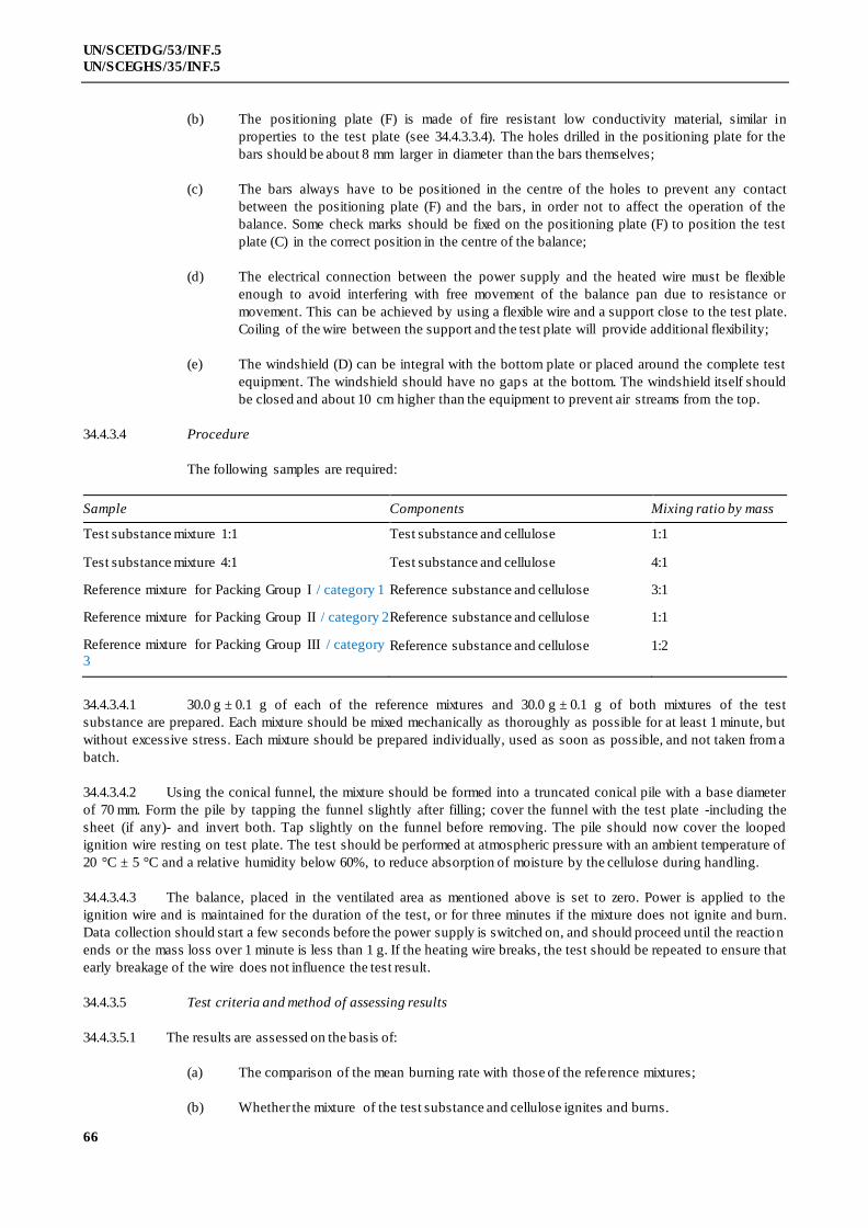
66
UN/SCETDG/53/INF.5
UN/SCEGHS/35/INF.5
(b) The positioning plate (F) is made of fire resistant low conductivity material, similar in
properties to the test plate (see 34.4.3.3.4). The holes drilled in the positioning plate for the
bars should be about 8 mm larger in diameter than the bars themselves;
(c) The bars always have to be positioned in the centre of the holes to prevent any contact
between the positioning plate (F) and the bars, in order not to affect the operation of the
balance. Some check marks should be fixed on the positioning plate (F) to position the test
plate (C) in the correct position in the centre of the balance;
(d) The electrical connection between the power supply and the heated wire must be flexible
enough to avoid interfering with free movement of the balance pan due to resistance or
movement. This can be achieved by using a flexible wire and a support close to the test plate.
Coiling of the wire between the support and the test plate will provide additional flexibility;
(e) The windshield (D) can be integral with the bottom plate or placed around the complete test
equipment. The windshield should have no gaps at the bottom. The windshield itself should
be closed and about 10 cm higher than the equipment to prevent air streams from the top.
34.4.3.4 Procedure
The following samples are required:
Sample Components Mixing ratio by mass
Test substance mixture 1:1 Test substance and cellulose 1:1
Test substance mixture 4:1 Test substance and cellulose 4:1
Reference mixture for Packing Group I / category 1 Reference substance and cellulose 3:1
Reference mixture for Packing Group II / category 2 Reference substance and cellulose 1:1
Reference mixture for Packing Group III / category
3 Reference substance and cellulose 1:2
34.4.3.4.1 30.0 g ± 0.1 g of each of the reference mixtures and 30.0 g ± 0.1 g of both mixtures of the test
substance are prepared. Each mixture should be mixed mechanically as thoroughly as possible for at least 1 minute, but
without excessive stress. Each mixture should be prepared individually, used as soon as possible, and not taken from a
batch.
34.4.3.4.2 Using the conical funnel, the mixture should be formed into a truncated conical pile with a base diameter
of 70 mm. Form the pile by tapping the funnel slightly after filling; cover the funnel with the test plate -including the
sheet (if any)- and invert both. Tap slightly on the funnel before removing. The pile should now cover the looped
ignition wire resting on test plate. The test should be performed at atmospheric pressure with an ambient temperature of
20 °C ± 5 °C and a relative humidity below 60%, to reduce absorption of moisture by the cellulose during handling.
34.4.3.4.3 The balance, placed in the ventilated area as mentioned above is set to zero. Power is applied to the
ignition wire and is maintained for the duration of the test, or for three minutes if the mixture does not ignite and burn.
Data collection should start a few seconds before the power supply is switched on, and should proceed until the reaction
ends or the mass loss over 1 minute is less than 1 g. If the heating wire breaks, the test should be repeated to ensure that
early breakage of the wire does not influence the test result.
34.4.3.5 Test criteria and method of assessing results
34.4.3.5.1 The results are assessed on the basis of:
(a) The comparison of the mean burning rate with those of the reference mixtures;
(b) Whether the mixture of the test substance and cellulose ignites and burns.

67
UN/SCETDG/53/INF.5
UN/SCEGHS/35/INF.5
34.4.3.5.2 The combustion of the conical pile can be divided into three periods:
(a) Start period: between 0% and 20% of the total mass loss;
(b) Main combustion period: between 20% and 80% of the total mass loss; and
(c) End of the reaction: between 80% mass loss and the end of the reaction.
In the main combustion period the mass loss per unit time is quite constant. For this reason a linear
regression (based on the least square approach) can be used to check the quality of the data collected.
34.4.3.5.3 The burning rate (BR) depends on the burning intensity and the amount of cellulose in the mixture. It is
therefore defined as the quotient of 60% of the total amount of cellulose in the conical pile and the main combustion
time t20-80. The time t20-80 is the time between 20% and 80% of the total mass loss. The total mass loss is the difference
in mass before ignition and at the end of the main reaction, defined as a rate of mass loss rate of less than 1 g per
minute.
The burning rate BR20-80 is therefore calculated by the following equation:
8020
8020
6.0
t
mBR cellulose
where:
BR20-80 = burning rate between 20% to 80% in g/s
mcellulose = mass of cellulose in mixture in gram
t20-80 = burning time between 20% to 80% of total mass loss in seconds
The profile of each burning test has to be examined by plotting the mass loss as a function of time.
The graph can also be used for decision making and should be used in case of doubt . The coefficient of correlation (R²)
of the mass curve of each burning test should be at least 0.95 between 20% to 80% mass loss, otherwise the burning
trial has to be repeated. Five valid tests should be performed with each reference and test substance mixture. The
standard deviation of the burning rates within these five tests should not exceed 10% in total.
34.4.3.5.4 The test criteria for determining transport Packing Groups / categories on basis of the oxidizing properties
of the substance are:
Packing Group I / category 1: Any substance which, in the 4:1 or 1:1 sample-to-cellulose ratio (by mass) tested,
exhibits a mean burning rate greater than the mean burning rate of a 3:1 mixture, by mass, of
calcium peroxide and cellulose.
Packing Group II / category 2: Any substance which, in the 4:1 or 1:1 sample-to-cellulose ratio (by mass) tested,
exhibits a mean burning rate equal to or greater than the mean burning rate of a 1:1 mixture
(by mass) of calcium peroxide and cellulose and the criteria for Packing Group I are not met.
Packing Group III / category 3: Any substance which, in the 4:1 or 1:1 sample-to-cellulose ratio (by mass) tested,
exhibits a mean burning rate equal to or greater than the mean burning rate of a 1:2 mixture
(by mass) of calcium peroxide and cellulose and the criteria for Packing Groups I and II are
not met.
Not an oxidizing solid Division 5.1: Any substance which, in both the 4:1 and 1:1 sample-to-cellulose ratio (by
mass) tested, does not ignite and burn, or exhibits mean burning rates less than that of a 1:2
mixture (by mass) of calcium peroxide and cellulose.
For the assignment of precedence of hazards for transport purposes in the case of substances having other hazards, e.g.
toxicity or corrosivity, the requirements of section 2.0.3 of the Model Regulations should be met.
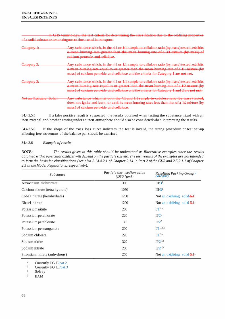
68
UN/SCETDG/53/INF.5
UN/SCEGHS/35/INF.5
In GHS terminology, the test criteria for determining the classification due to the oxidizing properties
of a solid substance are analogous to those used in transport:
Category 1: Any substance which, in the 4:1 or 1:1 sample-to-cellulose ratio (by mass) tested, exhibits
a mean burning rate greater than the mean burning rate of a 3:1 mixture (by mass) of
calcium peroxide and cellulose.
Category 2: Any substance which, in the 4:1 or 1:1 sample-to-cellulose ratio (by mass) tested, exhibits
a mean burning rate equal to or greater than the mean burning rate of a 1:1 mixture (by
mass) of calcium peroxide and cellulose and the criteria for Category 1 are not met.
Category 3: Any substance which, in the 4:1 or 1:1 sample-to-cellulose ratio (by mass) tested, exhibits
a mean burning rate equal to or greater than the mean burning rate of a 1:2 mixture (by
mass) of calcium peroxide and cellulose and the criteria for Category 1 and 2 are not met.
Not an Oxidizing Solid: Any substance which, in both the 4:1 and 1:1 sample-to-cellulose ratio (by mass) tested,
does not ignite and burn, or exhibits mean burning rates less than that of a 1:2 mixture (by
mass) of calcium peroxide and cellulose.
34.4.3.5.5 If a false positive result is suspected, the results obtained when testing the substance mixed with an
inert material and/or when testing under an inert atmosphere should also be considered when interpreting the results.
34.4.3.5.6 If the shape of the mass loss curve indicates the test is invalid, the mixing procedure or test set-up
affecting free movement of the balance pan should be examined.
34.4.3.6 Example of results
NOTE: The results given in this table should be understood as illustrative examples since the results
obtained with a particular oxidizer will depend on the particle size etc. The test results of the examples are not intended
to form the basis for classifications (see also 2.14.4.2.1 of Chapter 2.14 in Part 2 of the GHS and 2.5.2.1.1 of Chapter
2.5 in the Model Regulations, respectively).
Substance Particle size, median value
(D50 [µm]) Resulting Packing Group / category
Ammonium dichromate 300 III/31
Calcium nitrate (tetra hydrate) 1050 III/31
Cobalt nitrate (hexahydrate) 1200 Not an oxidizing solid 5.11
Nickel nitrate 1200 Not an oxidizing solid 5.11
Potassium nitrite 200 I/12,a
Potassium perchlorate 220 II/21
Potassium perchlorate 30 II/22
Potassium permanganate 200 I/11,2,a
Sodium chlorate 220 I/12,a
Sodium nitrite 320 II/21,b
Sodium nitrate 200 II/21,b
Strontium nitrate (anhydrous) 250 Not an oxidizing solid 5.11
a Currently PG II/cat.2 b Currently PG III/cat.3 1 Solvay 2 BAM
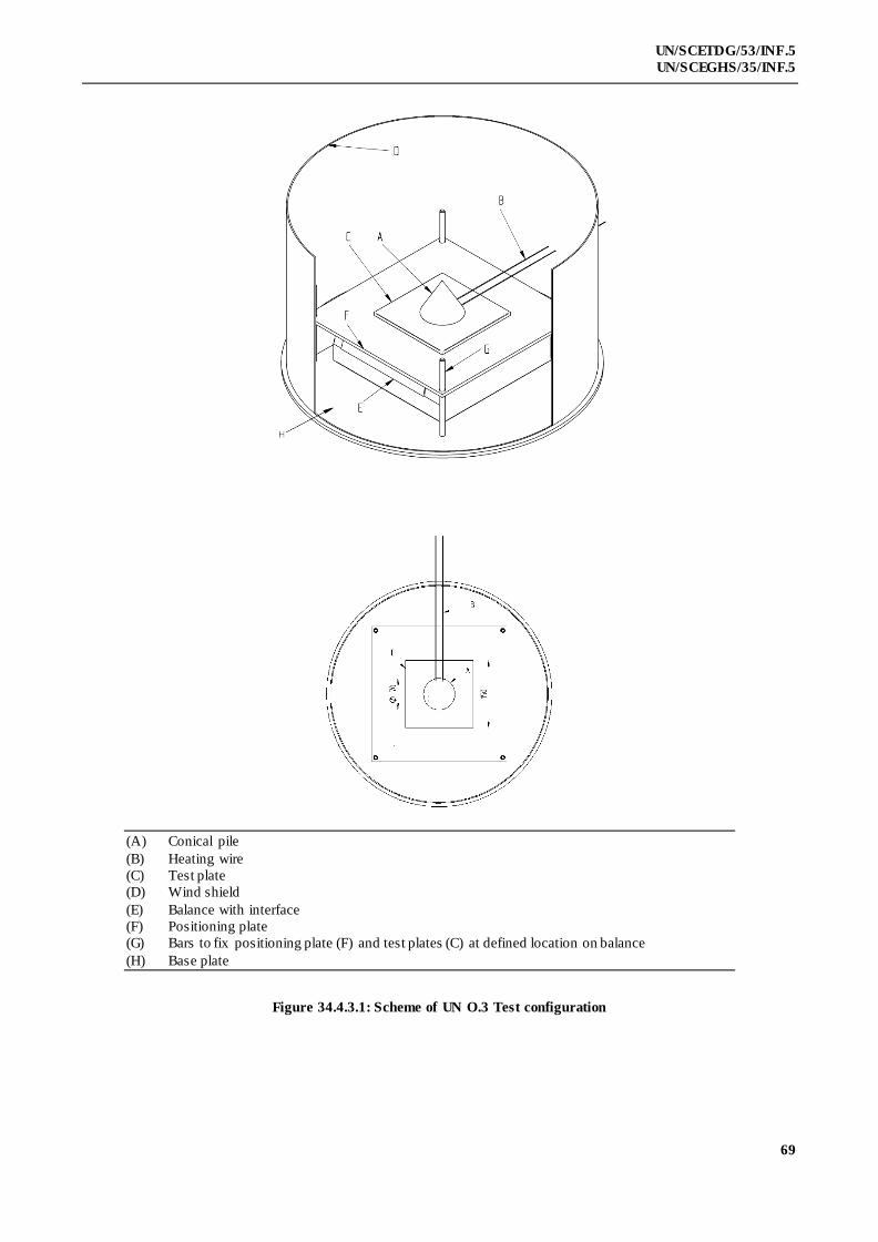
69
UN/SCETDG/53/INF.5
UN/SCEGHS/35/INF.5
(A) Conical pile
(B) Heating wire
(C) Test plate
(D) Wind shield
(E) Balance with interface
(F) Positioning plate
(G) Bars to fix positioning plate (F) and test plates (C) at defined location on balance
(H) Base plate
Figure 34.4.3.1: Scheme of UN O.3 Test configuration
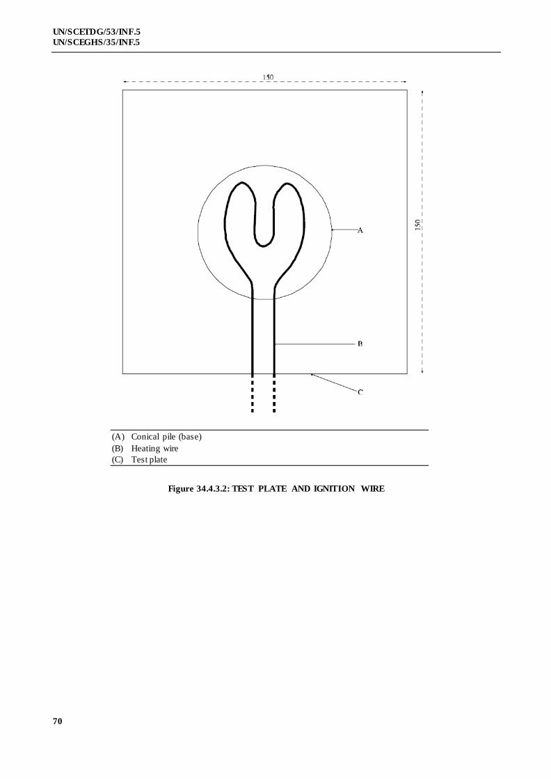
70
UN/SCETDG/53/INF.5
UN/SCEGHS/35/INF.5
(A) Conical pile (base)
(B) Heating wire
(C) Test plate
Figure 34.4.3.2: TEST PLATE AND IGNITION WIRE

71
UN/SCETDG/53/INF.5
UN/SCEGHS/35/INF.5
SECTION 35
DETERMINATION OF CHEMICAL INSTABILITY
OF GASES AND GAS MIXTURES
35.0 Introduction
This section presents the United Nations scheme for the classification of gases and gas mixtures as
chemically unstable. The text should be used in conjunction with the classification principles given in Chapter 2.2 of the
Globally Harmonized System of Classification and Labelling of Chemicals (GHS) and the test methods given in this
section.
35.1 Purpose
35.1.1 This test method is used to determine the chemical instability of a gas or gas mixture by ignition tests
in a closed vessel at ambient and elevated temperature and pressure.
35.1.2 For the purposes of this test method the following definitions apply:
Chemical instability means the propensity of a gas or gas mixture to react dangerously even in the
absence of any reaction partner (e.g. air or oxygen) by decomposing and thereby causing a temperature and/or pressure
increase;
Test gas means the gas or gas mixture to be evaluated by this test method;
Corresponding initial pressure means the pressure at which the test at 65 °C is carried out. For test
gases that are completely gaseous the corresponding initial pressure is the pressure that a gas develops at 65 °C based
on the maximum (filling) pressure at ambient temperature. For liquefied test gases the corresponding initial pressure is
the vapour pressure at 65 °C.
35.2 Scope
35.2.1 The test method does not cover gas decomposition under process conditions in chemical plants and
possible dangerous reactions between different gases in gas mixtures.
35.2.2 Mixtures of gases, where the components can react dangerously with each other, e.g. flammable and
oxidizing gases, are not regarded as chemically unstable in the sense of this test method.
35.2.3 If the calculations in accordance with ISO 10156:2010 show that a gas mixture is not flammable it is
not necessary to carry out the tests for determining chemical instability for classification purposes.
35.2.4 Expert judgement should be applied to decide whether a flammable gas or gas mixture is a candidate
for classification as chemically unstable in order to avoid unnecessary testing of gases where there is no doubt that they
are stable. Functional groups indicating chemical instability in gases are triple-bonds, adjacent or conjugated double-
bonds, halogenated double-bonds and strained rings.
35.3 Concentration limits
35.3.1 Generic concentration limits
35.3.1.1 Gas mixtures containing only one chemically unstable gas are not considered as chemically unstable
and therefore do not have to be tested for classification purposes if the concentration of the chemically unstable gas is
below the higher of the following generic concentration limits:
(a) The lower explosion limit (LEL) of the chemically unstable gas; or
(b) 3 mole percent (mol %).
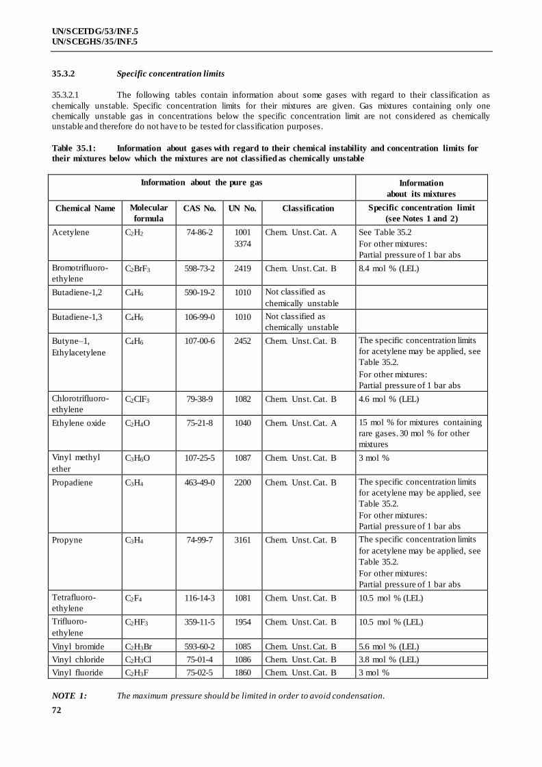
72
UN/SCETDG/53/INF.5
UN/SCEGHS/35/INF.5
35.3.2 Specific concentration limits
35.3.2.1 The following tables contain information about some gases with regard to their classification as
chemically unstable. Specific concentration limits for their mixtures are given. Gas mixtures containing only one
chemically unstable gas in concentrations below the specific concentration limit are not considered as chemically
unstable and therefore do not have to be tested for classification purposes.
Table 35.1: Information about gases with regard to their chemical instability and concentration limits for
their mixtures below which the mixtures are not classified as chemically unstable
Information about the pure gas Information
about its mixtures
Chemical Name Molecular
formula
CAS No. UN No. Classification Specific concentration limit
(see Notes 1 and 2)
Acetylene C2H2 74-86-2 1001
3374
Chem. Unst. Cat. A See Table 35.2
For other mixtures:
Partial pressure of 1 bar abs
Bromotrifluoro-
ethylene
C2BrF3 598-73-2 2419 Chem. Unst. Cat. B 8.4 mol % (LEL)
Butadiene-1,2 C4H6 590-19-2 1010 Not classified as
chemically unstable
Butadiene-1,3 C4H6 106-99-0 1010 Not classified as
chemically unstable
Butyne–1,
Ethylacetylene
C4H6 107-00-6 2452 Chem. Unst. Cat. B The specific concentration limits
for acetylene may be applied, see
Table 35.2.
For other mixtures:
Partial pressure of 1 bar abs
Chlorotrifluoro-
ethylene
C2ClF3 79-38-9 1082 Chem. Unst. Cat. B 4.6 mol % (LEL)
Ethylene oxide C2H4O 75-21-8 1040 Chem. Unst. Cat. A 15 mol % for mixtures containing
rare gases. 30 mol % for other
mixtures
Vinyl methyl
ether
C3H6O 107-25-5 1087 Chem. Unst. Cat. B 3 mol %
Propadiene C3H4 463-49-0 2200 Chem. Unst. Cat. B The specific concentration limits
for acetylene may be applied, see
Table 35.2.
For other mixtures:
Partial pressure of 1 bar abs
Propyne C3H4 74-99-7 3161 Chem. Unst. Cat. B The specific concentration limits
for acetylene may be applied, see
Table 35.2.
For other mixtures:
Partial pressure of 1 bar abs
Tetrafluoro-
ethylene
C2F4 116-14-3 1081 Chem. Unst. Cat. B 10.5 mol % (LEL)
Trifluoro-
ethylene
C2HF3 359-11-5 1954 Chem. Unst. Cat. B 10.5 mol % (LEL)
Vinyl bromide C2H3Br 593-60-2 1085 Chem. Unst. Cat. B 5.6 mol % (LEL)
Vinyl chloride C2H3Cl 75-01-4 1086 Chem. Unst. Cat. B 3.8 mol % (LEL)
Vinyl fluoride C2H3F 75-02-5 1860 Chem. Unst. Cat. B 3 mol %
NOTE 1: The maximum pressure should be limited in order to avoid condensation.
73
UN/SCETDG/53/INF.5
UN/SCEGHS/35/INF.5
NOTE 2: The test method is not applicable to liquefied gas mixtures. In case the gaseous phase above a liquefied
gas mixture may become chemically unstable after withdrawal, this shall be communicated via the safety data sheet.
Table 35.2: Specific concentration limits for binary mixtures with acetylene. These concentration limits may
also be applied to butyne-1 (ethylacetylene), propadiene and propyne
Concentration limit
for acetylene
in mol %
Maximum (filling) pressure in bar for a mixture with
N2 CO2 NH3 H2 CH4 C3H8 C2H4
3.0 200.0 200.0
4.0 100.0
5.0 40.0 40.0
6.0 80.0
8.0 60.0
10.0 50.0 38.0 5.6 20.0 100.0 6.0 20.0
15.0 30.0 30.0 10.0 10.0
20.0 25.0 20.0 6.2 5.0 50.0 6.6 7.5
25.0 20.0 15.0 5.0
30.0 10.0 10.0 6.9 25.0 7.3
35.0 7.3
40.0 15.0 8.2
45.0
50.0 5.0 9.3
60.0 10.8
35.4 Test method
35.4.1 Introduction
35.4.1.1 The propensity of a gas to decompose depends strongly on pressure, temperature and in case of gas
mixtures on the concentration of the chemically unstable component. The possibility of decomposition reactions shall
be evaluated at conditions which are relevant for handling and use and transport. Therefore two types of tests shall be
performed:
(a) At ambient temperature and pressure,
(b) At 65 °C and the corresponding initial pressure.
35.4.2 Apparatus and material
35.4.2.1 The test apparatus (see Figure 35.1) consist of a pressure resistant test vessel (heatable) made of stainless
steel; an ignition source; a measuring and recording system to record the pressure inside the ignition vessel; a gas
supply; a venting system with bursting disc and additional piping, fitted with remote-controlled valves and cocks.
(a) Pressure resistant test vessel
The test vessel is a cylindrical stainless steel vessel with an inner volume of about 1 dm3 and an
inner diameter of 80 mm. An exploding wire ignition source is screwed into the bottom of the
vessel. The vessel is equipped with a heating jacket which is connected to a temperature
control unit that heats the outer vessel wall with an accuracy of ± 2 K. The test vessel is
74
UN/SCETDG/53/INF.5
UN/SCEGHS/35/INF.5
insulated with temperature resistant insulation material to avoid heat loss and temperature
gradients. The test vessel shall be pressure resistant up to 500 bar (50 MPa).
(b) Exploding wire igniter
The ignition source is an exploding (fusing) wire igniter similar to that described in ASTM E
918 and EN 1839. The igniter consists of two insulated electrodes at 3 mm to 6 mm distance,
holding a nickeline wire of 0.12 mm diameter at its ends. The ignition energy is provided by a
1.5 kVA/230 (115) V insulating transformer, which is switched for a short time period to this
igniter. The wire melts and then an electrical arc burns between the electrodes for a period
extending in maximum to half a period of the supply voltage (10 (8.3) ms). An electronic
control unit allows switching different time periods of the mains voltage half wave to the
igniter. The corresponding energy delivered shall be in the range of 15 J ± 3 J. The energy can
be measured by recording the current and voltage during ignition.
(c) Pressure and temperature recording equipment
The pressure inside the ignition vessel shall be measured with a calibrated piezoresistive
pressure transducer. The measuring range shall be 20 times higher than the initial pressure. The
sensitivity shall be at least 0.1% of the full scale and the accuracy shall be better than 0.5% of
the full scale.
The temperature of the ignition vessel shall be measured and controlled with a 3 mm
thermocouple type “K” (NiCr/NiAl) mounted 50 mm below the top inside the autoclave.
After ignition the digitized pressure signal shall be recorded with a computer. The initial
pressure (p0) and the highest pressure (pex) are derived from the raw data.
(d) Gas supply
Two different types of gas supply are necessary, one for test gases that are completely in the
gaseous phase and one for liquefied test gases. Test gases in the gaseous phase are metered
volumetric or by flow measurement and liquefied test gases are metered gravimetric.
(e) Bursting disc
The bursting disc is supposed to protect the test vessel. It is connected to a vent pipe for the
exhaust gas. The free diameter of the bursting disc should be at least 10 mm, the inner diameter
of the pipe at least 15 mm. The opening pressure of the bursting disc shall amount to 250 bar
(25 MPa).
(f) Additional piping and valves
The piping and valves which are fitted directly to the test vessel, shall be pressure resistant up
to 500 bar (50 MPa). The test apparatus shall be operated by remotely operated valves.
35.4.3 Test procedure
35.4.3.1 The test gas is charged into a pressure resistant stainless steel vessel at controlled temperature and
pressure. The vessel is equipped with a bursting disc. Ignition of the test gas is achieved with an exploding wire igniter.
Whether a decomposition reaction has occurred is deduced from the pressure rise produced.
35.4.3.2 The tests shall be executed in the following sequence:
(a) Test at ambient temperature and pressure
For the tests at 20 °C and 1.01 bar (101.3 kPa) the exploding wire igniter shall be arranged in
the middle of the test vessel. The test vessel and the piping are evacuated. The test gas is filled
into the test vessel by using the remotely operated valves until ambient pressure (initial
75
UN/SCETDG/53/INF.5
UN/SCEGHS/35/INF.5
pressure) is reached. After closing the valves the igniter is fired. The ignition energy shall be
about 15 J to avoid over-initiation in the test vessel at this relatively low pressure. Criterion for
a reaction is a pressure rise of more than 20% after ignition (f = pex/p0 > 1.20). If no such
pressure rise has occurred two further re-tests shall be carried out.
If the test gas shows a pressure rise of more than 20% in either of the tests it is to be classified
as "chemically unstable at 20 °C and a standard pressure of 101.3 kPa". No further tests are
required.
(b) Test at elevated temperature and pressure
If in the tests according to 35.4.3.2 (a) no pressure rise of more than 20% has occurred, further
tests at 65 °C and the corresponding initial pressure shall be performed. The procedure is the
same as in 35.3.3.2 (a) but care should be taken with potentially unstable gases under pressure.
The ignition energy shall be about 15 J. If no pressure rise of more than 20% has occurred two
further re-tests shall be carried out.
If the test gas shows a pressure rise of more than 20% in either of the tests it is to be classified
as "chemically unstable at a temperature greater than 20 °C and/or a pressure greater than
101.3 kPa".
35.4.4 Safety precautions
35.4.4.1 Adequate shielding of the test apparatus must be provided to prevent injury in the event of equipment
rupture. The apparatus is to be set up in such a way that the operator does not have to be in the same room as long as the
vessel contains test gas. Alternatively, the test apparatus is separated by a blast proof barrier from the operator.
Activation of the ignition source should be possible only from a position shielded from the test vessel.
35.4.4.2 The test vessel shall be fitted with a bursting disc connected to a vent pipe that allows venting the exhaus t
gas safely. Therefore it has to be taken into account that the exhaust gas can be hazardous itself (e.g. flammable or
toxic).
35.4.4.3 The gas cylinder containing the test gas shall be equipped with a non-return valve and shall be separated
from the test apparatus before the igniter is fired to avoid backfiring into the cylinder. The cylinder valve has to be
closed immediately after finishing the filling.
35.4.4.4 Some chemically unstable gases can explode very violently especially at higher pressures. Therefore it is
strongly recommended to start with the experiments at atmospheric pressure.
35.4.5 Test criteria and method of assessing results
35.4.5.1 Chemically unstable gases or gas mixtures shall be classified as “chemically unstable at 20 °C and a
standard pressure of 101.3 kPa” or “chemically unstable at a temperature greater than 20 °C and/or a pressure greater
than 101.3 kPa” according to the test results as follows:
(a) The gas is classified as “chemically unstable at 20 °C and a standard pressure of 101.3 kPa” if
the test at 20 °C and 1.01 bar (101.3 kPa) shows a pressure rise of more than 20% of the initial
absolute pressure;
(b) The gas is classified as “chemically unstable at a temperature greater than 20 °C and/or a
pressure greater than 101.3 kPa” if the test at 65 °C and the corresponding initial pressure
shows a pressure rise of more than 20% of the initial absolute pressure but no such pressure
rise at 20 °C and 1.01 bar (101.3 kPa).
35.4.5.2 The gas is not classified according to this test method (i.e. it is chemically stable) if it does not show a
pressure rise of more than 20% of the initial absolute pressure in either of the tests.
NOTE: Chemically unstable gases not submitted to the classification procedure in this section should be
classified as chemically unstable, Category A (see Chapter 2.2 of the GHS).

76
UN/SCETDG/53/INF.5
UN/SCEGHS/35/INF.5
waste gas
ER
2
5
7
9
pressurized Helium
Test su
bsta
nce
3
1
waste gas
10
Test su
bsta
nce
PIR
TIC
M
M
4
6
8
11
A B
C
DE
F
G
H
I
J
K
L
L
N
PQ
P
(A) Test gas supply (gaseous) (B) Test gas supply (liquefied)
(C) Pressure resistant test vessel (D) Regulated electric heater
(E) Thermal insulation (F) Exploding wire igniter
(G) Pressure sensor, pressure indication and
registration (PIR)
(H) Bursting disc
(I) Electronic ignition device (J) Energy registration (ER)
(K) Vacuum pump (L) Exhaust gas
(M) Motor controlled valve (N) Pressurized helium
(P) Test gas (Q) Temperature sensor, temperature
indication and control (TIC)
Figure 35.1: TEST APPARATUS

77
UN/SCETDG/53/INF.5
UN/SCEGHS/35/INF.5
[36. Reserved for classification procedures, test methods and criteria relating to Class 7]

UN/SCETDG/53/INF.5
UN/SCEGHS/35/INF.5
78
SECTION 37
CLASSIFICATION PROCEDURES, TEST METHODS AND CRITERIA
RELATING TO SUBSTANCES CORROSIVE TO METALS OF CLASS 8
37.1 Purpose
37.1.1 This section presents the United Nations scheme for the classification of substances corrosive to metal
substances of Class 8 (see sections 2.8.1 and 2.8.2 of the Model Regulations and Chapter 2.16 of the GHS).
37.1.2 The test method for corrosion is given in sub-section 37.4 of this Manual. The method for determining
corrosion to skin is provided in OECD Guideline 404 or 435 and the criteria are provided in Chapter 2.8 of the Model
Regulations and Chapter 3.2 of the GHS. If a substance is shown to be corrosive to skin, then it is not necessary to
conduct the tests for metal corrosion for the purposes of classification.
37.1.3 In assigning the packing group to a substance or mixture in accordance with Chapter 2.8, paragraph
2.8.2.2 of the Model Regulations, account shall be taken of human experience in instances of accidental exposure. In the
absence of human experience, the grouping shall be based on data obtained from experiments with OECD test
guidelines 404 or 435. A substance or mixture which is determined not to be corrosive in accordance with OECD test
guideline 430 or 431 may be considered not to be corrosive to skin for the purposes of classification without further
testing.
37.2 Scope
37.2.1 New products offered for transport shall be subjected to the classification procedures as set out in
paragraph 2.8.2.5 (c) (ii) of the Model Regulations and paragraph 2.16.2 of the GHS unless it is impracticable (e.g.
because of the physical properties) to perform the tests. Substances which cannot be tested shall be classified by
analogy with existing entries. The classification procedure shall be undertaken before a new product is offered for
transport.
37.3 Classification procedure
The following test procedures are designed to assess the corrosion hazard for an appropriate
classification for transport.
37.4 Test methods for corrosion to metals
37.4.1 Introduction
37.4.1.1 Test C.1: Test for determining the corrosive properties of liquids and solids that may become liquid
during transport as dangerous goods of Class 8as a substance corrosive to metal, packing group III / category 1.
37.4.2 Apparatus and material
For exposure to the medium being classified the specimens shall consist of 2 mm thick plates and
shall be made of the following materials:
- Aluminium, non-clad types 7075-T6 or AZ5GU-T6 and
- Steel type, S235JR+CR (1.0037 resp. St 37-2), S275J2G3+CR (1.0144 resp. St 44-3),
ISO 3574, Unified Numbering System (UNS) G10200 or SAE 1020 (see Figure 37.4.1).

UN/SCETDG/53/INF.5
UN/SCEGHS/35/INF.5
79
2 0 m m
50
m
m
Ø 3 m m
Figure 37.4.2.1: SPECIMEN
At least 3 sets of specimens shall be used for each metal (aluminium, steel). A cup-like reaction receptacle (of glass or
PTFE) as shown in Figure 37.4.2.2 with three necks of suitable size (e.g. NS92/32 as well as one neck NS14) to
accommodate the specimen as illustrated in Figure 37.4.2.1 and a fourth neck of sufficient size to accommodate a reflux
condenser shall be used. The entrance of air into the receptacle shall be ensured. Aluminium and steel specimens shall
be tested in different reaction receptacles . To prevent liquid loss a reflux condenser shall be attached (see
Figure 37.4.2.2).
Figure 37.4.2.2: EXPOSURE RECEPTACLE WITH REFLUX CONDENS ER
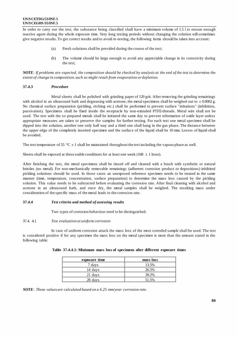
UN/SCETDG/53/INF.5
UN/SCEGHS/35/INF.5
80
In order to carry out the test, the substance being classified shall have a minimum volume of 1.5 l to ensure enough
reactive agent during the whole exposure time. Very long testing periods without changing the solution will sometimes
give negative results. To get correct results and to avoid re-testing, the following items should be taken into account:
(a) Fresh solutions shall be provided during the course of the test;
(b) The volume should be large enough to avoid any appreciable change in its corrosivity during
the test;
NOTE: If problems are expected, the composition should be checked by analysis at the end of the test to determine the
extent of change in composition, such as might result from evaporation or depletion.
37.4.3 Procedure
Metal sheets shall be polished with grinding paper of 120 grit. After removing the grinding remainings
with alcohol in an ultrasound bath and degreasing with acetone, the metal specimens shall be weighed out to ± 0.0002 g.
No chemical surface preparation (pickling, etching etc.) shall be performed to prevent surface "irritations" (inhibition,
passivation). Specimens shall be fixed inside the receptacle by non-extruded PTFE-threads. Metal wire shall not be
used. The test with the so prepared metals shall be initiated the same day to prevent reformation of oxide layer unless
appropriate measures are taken to preserve the samples for further testing. For each test one metal specimen shall be
dipped into the solution, another one only half way and a third one shall hang in the gas phase. The distance between
the upper edge of the completely inserted specimen and the surface of the liquid shall be 10 mm. Losses of liquid shall
be avoided.
The test temperature of 55 °C ± 1 shall be maintained throughout the test including the vapour phase as well.
Sheets shall be exposed at these stable conditions for at least one week (168 ± 1 hour).
After finishing the test, the metal specimens shall be rinsed off and cleaned with a brush with synthetic or natural
bristles (no metal). For non-mechanically removable remainings (adherent corrosion product or depositions) inhibited
pickling solutions should be used. In those cases an unexposed reference specimen needs to be treated in the same
manner (time, temperature, concentration, surface preparation) to determine the mass loss caused by the pickling
solution. This value needs to be subtracted before evaluating the corrosion rate. After final cleaning with alcohol and
acetone in an ultrasound bath, and once dry, the metal samples shall be weighed. The resulting mass under
consideration of the specific mass of the metal leads to the corrosion rate.
37.4.4 Test criteria and method of assessing results
Two types of corrosion behaviour need to be distinguished.
37.4. 4.1 Test evaluation at uniform corrosion
In case of uniform corrosion attack the mass loss of the most corroded sample shall be used. The test
is considered positive if for any specimen the mass loss on the metal specimen is more than the amount stated in the
following table:
Table 37.4.4.1: Minimum mass loss of specimens after different exposure times
exposure time mass loss
7 days 13.5%
14 days 26.5%
21 days 39.2%
28 days 51.5%
NOTE: These values are calculated based on a 6.25 mm/year corrosion rate.

UN/SCETDG/53/INF.5
UN/SCEGHS/35/INF.5
81
37.4.4.2 Test evaluation at localised corrosion
When localised corrosion occurs besides or instead of uniform corrosion attack of surface, the depth
of the deepest hole respectively the strongest thickness reduction will be added or only be used to determine the
intrusion. If the deepest intrusion (to be determined metallographically) exceeds the values shown in the following
table, the result is considered positive.
Table 37.4.4.2: Minimum intrusion depths after exposure time
exposure time min. intrusion depth
7 days 120 µm
14 days 240 µm
21 days 360 µm
28 days 480 µm

UN/SCETDG/53/INF.5
UN/SCEGHS/35/INF.5
83
SECTION 38
CLASSIFICATION PROCEDURES, TEST METHODS AND
CRITERIA RELATING TO SUBSTANCES AND ARTICLES
OF TRANSPORT CLASS 9
38.1 Introduction
This section contains classification procedures, test methods and criteria relating to substances and
articles of transport Class 9.
38.2 Ammonium nitrate based fertilizers capable of self-sustaining decomposition
38.2.1 Purpose
38.2.1.1 This section of the Manual presents the United Nations scheme for the classification of ammonium
nitrate based fertilizers of transport Class 9 (see UN 2071 and special provision 193 of the Model Regulations). The test
procedure is designed to assess if an ammonium nitrate based fertilizer is capable of undergoing self-sustaining
decomposition.
38.2.2 Scope
New products offered for transport should be subjected to the classificatio n procedure if the
composition is covered by the definition for UN 2071. The classification procedure should be undertaken before a new
product is offered for transport.
38.2.3 Classification procedure
38.2.3.1 The test method should be performed to determine if a decomposition initiated in a localised area will
spread throughout the mass. The recommended test method is given in 38.2.4. Whether the substance is an ammonium
nitrate based fertilizer of transport Class 9, or not, is decided on the basis of the test result.
38.2.3.2 Packing group III is assigned to all transport Class 9 ammonium nitrate based fertilizers.
38.2.3.3 Ammonium nitrate based fertilizers with the composition given for UN 2071 may be reg arded as not
subject to the Model Regulations if shown not to be liable to self-sustaining decomposition and provided that they do
not contain an excess of nitrate greater than 10% by mass (calculated as potassium nitrate).
38.2.3.43 The overall classification procedure for ammonium nitrate based fertilizers is set out in Section 39.
38.2.4 Test S.1: Trough test for determination of the self-sustaining exothermic decomposition of
fertilizers containing nitrates
38.2.4.1 Introduction
A fertilizer capable of self-sustaining decomposition is defined as one in which decomposition
initiated in a localized area will spread throughout the mass. The tendency of a fertilizer, to be offered for transport, to
undergo this type of decomposition can be determined by means of the Trough test. In this test localized decomposition
is initiated in a bed of the fertilizer contained in a horizontally mounted trough. The amount of propagation, after
removal of the initiating heat source, of decomposition through the mass is measured.
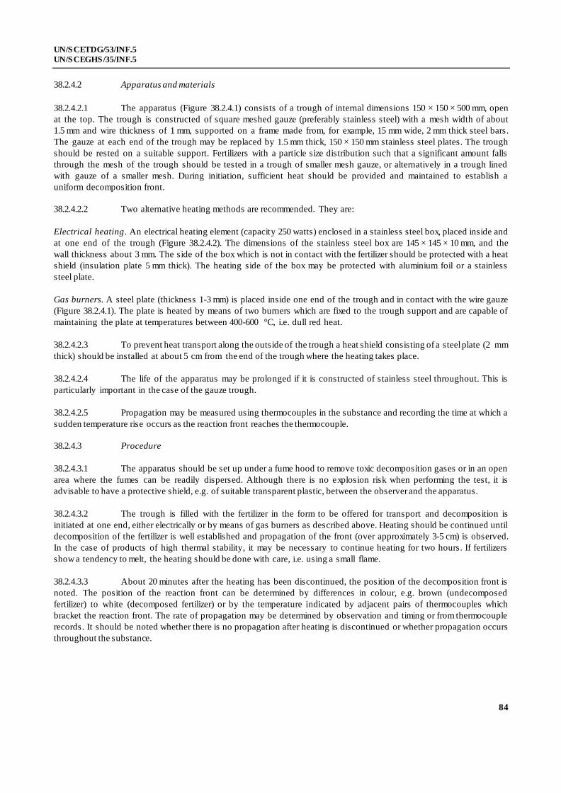
UN/SCETDG/53/INF.5
UN/SCEGHS/35/INF.5
84
38.2.4.2 Apparatus and materials
38.2.4.2.1 The apparatus (Figure 38.2.4.1) consists of a trough of internal dimensions 150 × 150 × 500 mm, open
at the top. The trough is constructed of square meshed gauze (preferably stainless steel) with a mesh width of about
1.5 mm and wire thickness of 1 mm, supported on a frame made from, for example, 15 mm wide, 2 mm thick steel bars.
The gauze at each end of the trough may be replaced by 1.5 mm thick, 150 × 150 mm stainless steel plates. The trough
should be rested on a suitable support. Fertilizers with a particle size distribution such that a significant amount falls
through the mesh of the trough should be tested in a trough of smaller mesh gauze, or alternatively in a trough lined
with gauze of a smaller mesh. During initiation, sufficient heat should be provided and maintained to establish a
uniform decomposition front.
38.2.4.2.2 Two alternative heating methods are recommended. They are:
Electrical heating. An electrical heating element (capacity 250 watts) enclosed in a stainless steel box, placed inside and
at one end of the trough (Figure 38.2.4.2). The dimensions of the stainless steel box are 145 × 145 × 10 mm, and the
wall thickness about 3 mm. The side of the box which is not in contact with the fertilizer should be protected with a heat
shield (insulation plate 5 mm thick). The heating side of the box may be protected with aluminium foil or a stainless
steel plate.
Gas burners. A steel plate (thickness 1-3 mm) is placed inside one end of the trough and in contact with the wire gauze
(Figure 38.2.4.1). The plate is heated by means of two burners which are fixed to the trough support and are capable of
maintaining the plate at temperatures between 400-600 °C, i.e. dull red heat.
38.2.4.2.3 To prevent heat transport along the outside of the trough a heat shield consisting of a steel plate (2 mm
thick) should be installed at about 5 cm from the end of the trough where the heating takes place.
38.2.4.2.4 The life of the apparatus may be prolonged if it is constructed of stainless steel throughout. This is
particularly important in the case of the gauze trough.
38.2.4.2.5 Propagation may be measured using thermocouples in the substance and recording the time at which a
sudden temperature rise occurs as the reaction front reaches the thermocouple.
38.2.4.3 Procedure
38.2.4.3.1 The apparatus should be set up under a fume hood to remove toxic decomposition gases or in an open
area where the fumes can be readily dispersed. Although there is no explosion risk when performing the test, it is
advisable to have a protective shield, e.g. of suitable transparent plastic, between the observer and the apparatus.
38.2.4.3.2 The trough is filled with the fertilizer in the form to be offered for transport and decomposition is
initiated at one end, either electrically or by means of gas burners as described above. Heating should be continued until
decomposition of the fertilizer is well established and propagation of the front (over approximately 3-5 cm) is observed.
In the case of products of high thermal stability, it may be necessary to continue heating for two hours. If fertilizers
show a tendency to melt, the heating should be done with care, i.e. using a small flame.
38.2.4.3.3 About 20 minutes after the heating has been discontinued, the position of the decomposition front is
noted. The position of the reaction front can be determined by differences in colour, e.g. brown (undecomposed
fertilizer) to white (decomposed fertilizer) or by the temperature indicated by adjacent pairs of thermocouples which
bracket the reaction front. The rate of propagation may be determined by observation and timing or from thermocouple
records. It should be noted whether there is no propagation after heating is discontinued or whether propagation occurs
throughout the substance.

UN/SCETDG/53/INF.5
UN/SCEGHS/35/INF.5
85
38.2.4.4 Test criteria and method of assessing results
38.2.4.4.1 If propagation of the decomposition continues throughout the substance, the fertilizer is considered
capable of showing self-sustaining decomposition.
38.2.4.4.2 If propagation does not continue throughout the substance, the fertilizer is considered to be free from
the hazard of self-sustaining decomposition.
38.2.4.4.3 Examples of results
NOTE: The NPK proportions for a fertilizer should not be used as a guide to its ability to undergo self-sustaining
decomposition as this depends on the chemical species present.
Substance Distance propagated (cm) Result
Compound fertilizer NPK 17-11-22 a 50 +
Compound fertilizer NPK 15-11-8 a 10 -
Compound fertilizer NPK 14-14-14 a 10 -
Compound fertilizer NPK 21-14-14 a 10 -
Compound fertilizer NPK 12-12-18 b 50 +
a Containing chloride. b Containing traces of cobalt and copper but less than 1% chloride.

UN/SCETDG/53/INF.5
UN/SCEGHS/35/INF.5
86
(A) Steel plate ( 150 × 150 mm and 1 to 3 mm thick)
(B) Gas burners (e.g. Teclu or Bunsen)
(C) Heat shield (2 mm thick)
(D) Stand (e.g. made from 15 mm wide, 2 mm thick steel bar)
(E) Gauze trough (150 × 150 × 500 mm)
Figure 38.2.4.1: GAUZE TROUGH WITH SUPPORT BURNERS
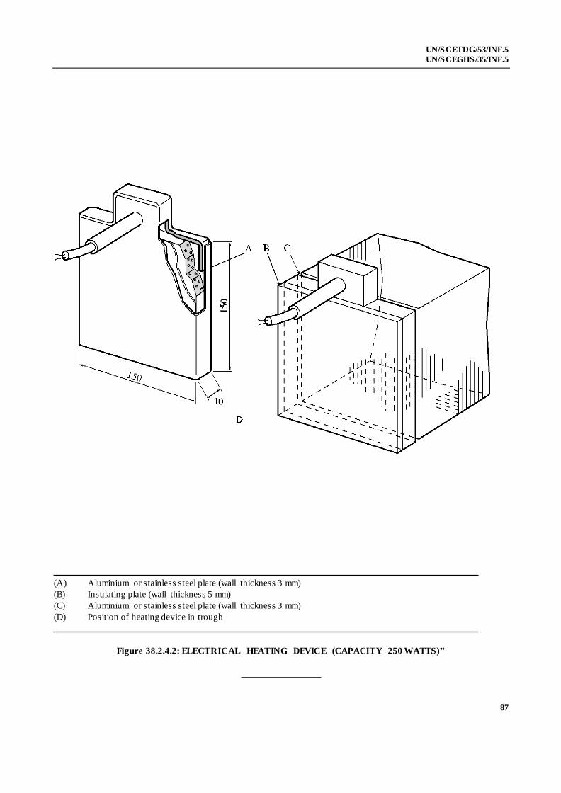
UN/SCETDG/53/INF.5
UN/SCEGHS/35/INF.5
87
(A) Aluminium or stainless steel plate (wall thickness 3 mm)
(B) Insulating plate (wall thickness 5 mm)
(C) Aluminium or stainless steel plate (wall thickness 3 mm)
(D) Position of heating device in trough
Figure 38.2.4.2: ELECTRICAL HEATING DEVICE (CAPACITY 250 WATTS)”