unmanned aerial vehicle for urban surveillance
TRANSCRIPT
2013
Md Ahsen Parwez
Dept of Mechanical Engineering
Roll no: 11416
IIT Kanpur
Mentor: Prof Bhaskar Dasgupta
PROJECT “HAWK EYE”
1
1. INTRODUCTION UAV (Unmanned Aerial Vehicle), popularly known as drone, is an aircraft without a human pilot on board. UAVs can be remote controlled aircraft (e.g. flown by a pilot at a ground control station) or can fly autonomously based on pre-programmed flight plans or more complex dynamic automation systems. The typical launch and recovery method of an unmanned aircraft is by the function of an automatic system or an external operator on the ground. There are a wide variety of UAV shapes, sizes, configurations, and characteristics. Historically, UAVs were simple remotely piloted aircraft, but autonomous control is increasingly being employed.
2. REVIEW OF PRIOR WORK A.M.Low’s “Aerial Target”, developed in 1916, is usually credited as the first attempt at modeling a powered unmanned craft. World War I saw a great surge in the number of UAV, including the Hewitt-Sperry Automatic Airplane. The first scale RPV (Remote Piloted Vehicle) was developed by the film star and model airplane enthusiast Reginald Denny in 1935. Jet engines were employed after World War II, while companies like Beechcraft also got in the game with their Model 1001 for the United States Navy in 1955. The birth of U.S. UAVs (called RPVs at the time) began in 1959 when United States Air Force (USAF) officers, concerned about losing pilots over hostile territory, began planning for the use of unmanned flights. A highly classified UAV program was launched under the code name of "Red Wagon", whose first combat mission was in the Vietnamese War. This was officially confirmed by U.S. military officials only on 26th Feb, 1973. As of now, there are two prominent UAV programs within the United States: that of the military and that of the CIA.
3. NOTABLE APPLICATIONS 3.1 AERIAL SURVEILLANCE
Aerial surveillance of large areas is made possible with low cost UAV systems. Surveillance applications include livestock monitoring, wildfire mapping, pipeline security, home security, road patrol, and anti-piracy.
3.2 POLICE
UAVs are increasingly used for domestic police work in Canada and the United States: a dozen US police forces had applied for UAV permits by March 2013.

2
3.3 OIL, GAS AND MINERAL EXPLORATION
UAVs can be used to perform geophysical surveys, in particular geomagnetic surveys where the processed measurements of the Earth's differential magnetic field strength are used to calculate the nature of the underlying magnetic rock structure, which can help predict the location of mineral resources.
3.4 TRANSPORT
UAVs can transport goods using various means based on the configuration of the UAV itself. The payload can either be placed inside the frame or tethered to the bottom of the air frame, as in a helicopter.
3.5 SCIENTIFIC RESEARCH
Unmanned aircraft are especially useful in penetrating areas that may be too dangerous for manned aircraft, such as hurricanes, ocean floors, volcanoes, glaciers etc.
3.6 ARMED ATTACKS
UAVs armed with Hellfire missiles are increasingly used by the U.S. as platforms for hitting ground targets. Armed Predators were first used in late 2001 from bases in Pakistan and Uzbekistan, mostly aimed at assassinating high profile individuals (terrorist leaders, etc.) inside Afghanistan. The advantage of using an unmanned vehicle rather than a manned aircraft in such cases is to avoid a diplomatic embarrassment should the aircraft be shot down and the pilots captured, since the bombings take place in countries deemed friendly and without the official permission of those countries.
3.7 CIVILIAN CASUALTIES
Questions have been raised about the accuracy of UAV-based missile strikes. In March 2009, The Guardian reported allegations that Israeli UAVs armed with missiles killed 48 Palestinian civilians in the Gaza Strip, including two small children in a field and a group of women and girls in an otherwise empty street. Although it may never be known how many civilians have died as a result of U.S. UAV strikes in Pakistan, there are estimates of hundreds or thousands of innocent bystanders who have perished in such attacks.
3.8 AERIAL TARGET PRACTICE
Since 1997, the U.S. military has used more than 80 F-4 Phantoms converted into robotic planes for use as aerial targets for combat training of human pilots. The F-4s were supplemented in September 2013 with F-16s as more realistically maneuverable targets.
3.9 SEARCH AND RECSUE
UAVs will likely play an increased role in search and rescue in the United States. This was demonstrated by the use of UAVs during the 2008 hurricanes that struck Louisiana and Texas.
3
3.10 FOREST FIRE DETECTION
Another application of UAVs is the prevention and early detection of forest fires. The possibility of constant flight, both day and night, makes the methods used until now (helicopters, watchtowers, etc.) become obsolete.
3.11 ARCHAEOLOGY
In Peru archaeologists use drones to speed up survey work and protect sites from squatters, builders and miners. Small drones helped researchers produce three-dimensional models of Peruvian sites instead of the usual flat maps.
4. HAWK EYE Of all the uses mentioned above, we had to design a UAV that can facilitate urban surveillance. We named our UAV “Hawk Eye”. This UAV is spherical in shape and can take-off and land vertically. This class of UAV’s, called VTOLs (Vertical Take-off and Landing) has proved to be quite effective for urban surveillance where it can provide a detailed view of a given map.
5. DESIGN Our UAV is in spherical in shape, which allows the user to land the bot in any orientation, since it will roll and come to the upright position for the next take off soon after it lands on ground. Inside the spherical body, a propeller is placed which is used to create lift. Below the prop we have 4 control surfaces which are used to create sideward thrust. These plates are placed at right angles to other plates in “+” shape at the equator of the sphere. Due to this “+” shape, the bot will face a heavy drag since air strikes the surface perpendicularly. In order to reduce this air drag, duct has been placed outside this “+” which provides streamlined flow of air. The control surfaces will have two parts, one fixed and one movable. The movable part will be controlled by servos which are attached to the fixed part. The central part where all control surfaces will meet perpendicularly will contain ardu-pilot, servo motors and Esc, which would help in controlling and Brushless DC motor & rechargeable battery for moving the propeller.
4
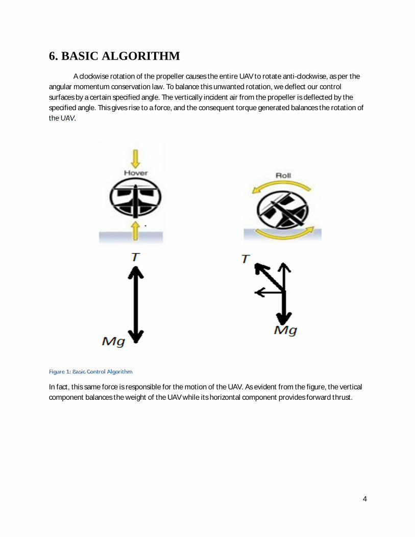
6. BASIC ALGORITHM A clockwise rotation of the propeller causes the entire UAV to rotate anti-clockwise, as per the angular momentum conservation law. To balance this unwanted rotation, we deflect our control surfaces by a certain specified angle. The vertically incident air from the propeller is deflected by the specified angle. This gives rise to a force, and the consequent torque generated balances the rotation of the UAV.
Figure 1: Basic Control Algorithm
In fact, this same force is responsible for the motion of the UAV. As evident from the figure, the vertical component balances the weight of the UAV while its horizontal component provides forward thrust.
5
7. SPECIFICATIONS 7.1. SKELETON
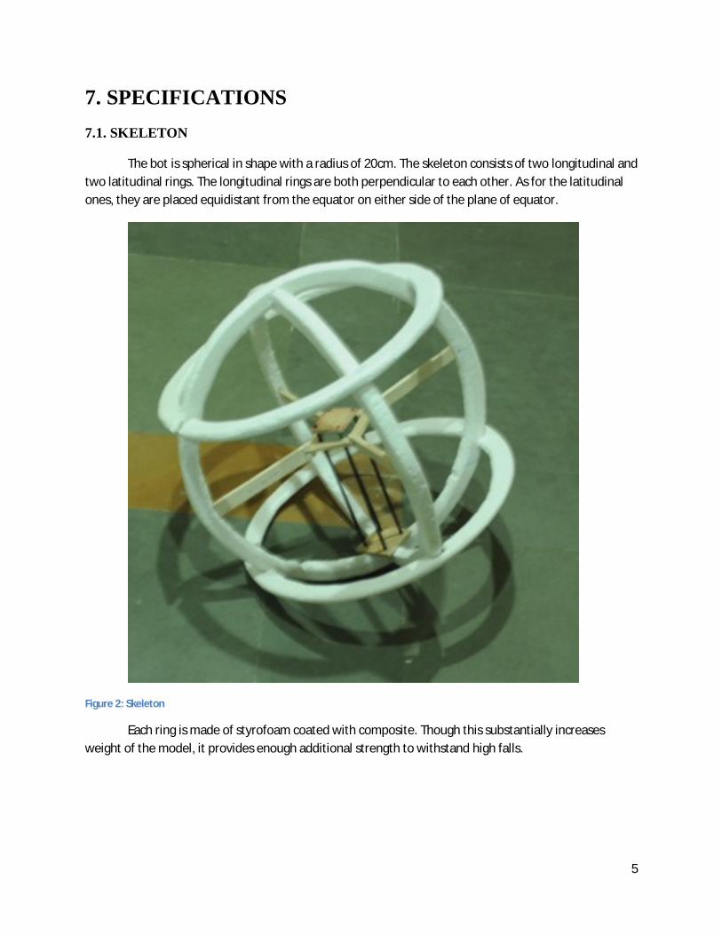
The bot is spherical in shape with a radius of 20cm. The skeleton consists of two longitudinal and two latitudinal rings. The longitudinal rings are both perpendicular to each other. As for the latitudinal ones, they are placed equidistant from the equator on either side of the plane of equator.
Figure 2: Skeleton
Each ring is made of styrofoam coated with composite. Though this substantially increases weight of the model, it provides enough additional strength to withstand high falls.
6
7.2 INTERNAL DESIGN
The central structure comprises of a truncated square pyramid. We have used a composite of balsa and glass fiber for the platforms. This composite is light and hard and well suited for our needs. Hollow carbon rods connect the two platforms and are joined to platforms by screws and bond-tite. The top platform supports the motor and the bottom one supports the battery and receiver.
Four fins are attached to the four corners of the top platform with their lengths along the diagonals of the square. The fins are made of balsa wood. This material is light and weaker than the composite. The control surfaces made of balsa ply are connected to the fins by light weight steel rods.
We have used an 11x5.5 propeller. This size is the most optimal for our given DC motor rating. This optimum value was reached through test flights using various propeller sizes. Also, the manufacturer’s rating claimed that it can provide the desired thrust using the given DC motor.
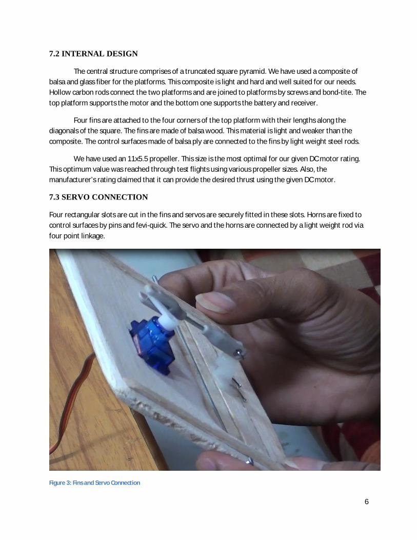
7.3 SERVO CONNECTION
Four rectangular slots are cut in the fins and servos are securely fitted in these slots. Horns are fixed to control surfaces by pins and fevi-quick. The servo and the horns are connected by a light weight rod via four point linkage.
Figure 3: Fins and Servo Connection
7
7.4 ELECTRICAL COMPONENTS
We have used a brushless DC Motor capable of providing a thrust of 1.7kgf with a 11 x 4.7 and uses an ESC for its control. This is powered by a Li-Po rechargeable battery. For stability we have used 6 DOF IMU (Inertial Measurement Unit). This is connected to arduino-uno board to complete the circuit.
8. FIRST TEST FLIGHT 8.1 VENUE
Airstrip, IIT Kanpur
8.2 PURPOSE
To check the thrust required for the model to hover and whether the model is strong enough to sustain that thrust.
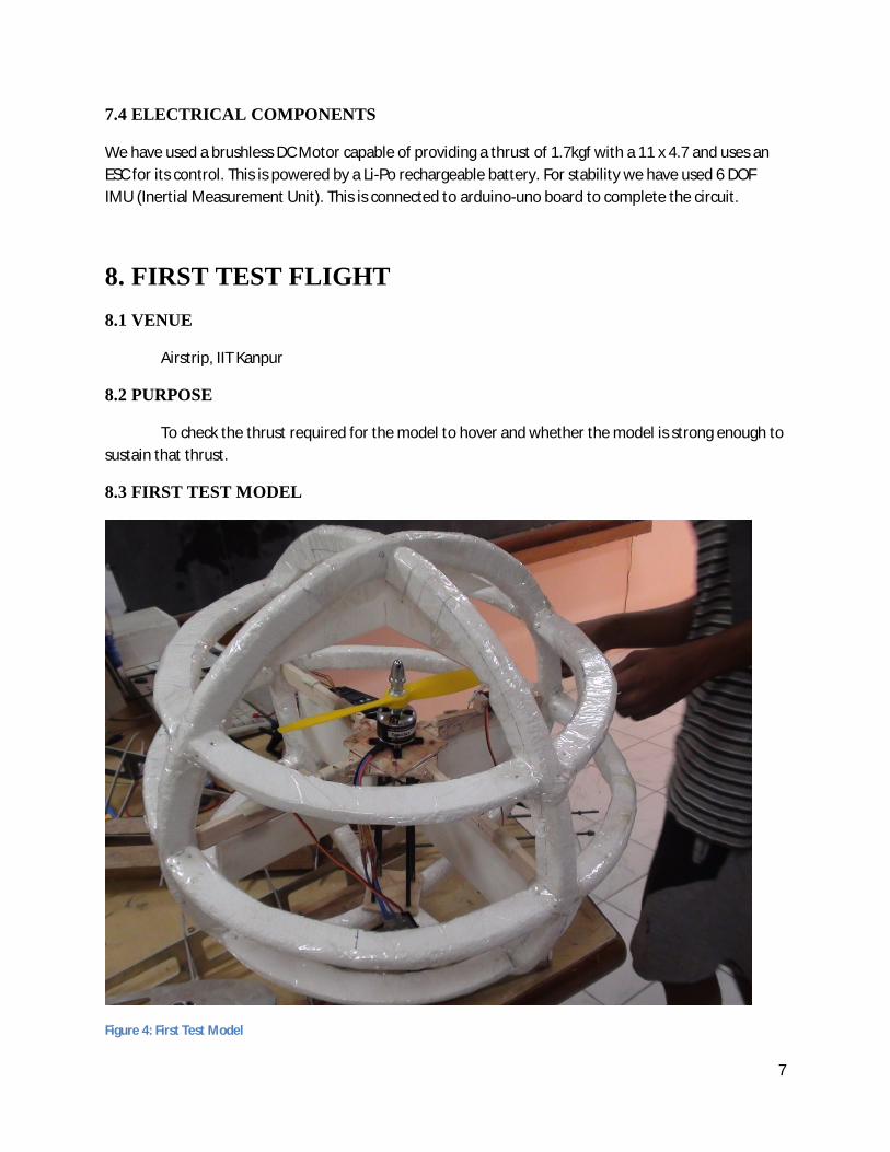
8.3 FIRST TEST MODEL
Figure 4: First Test Model
8
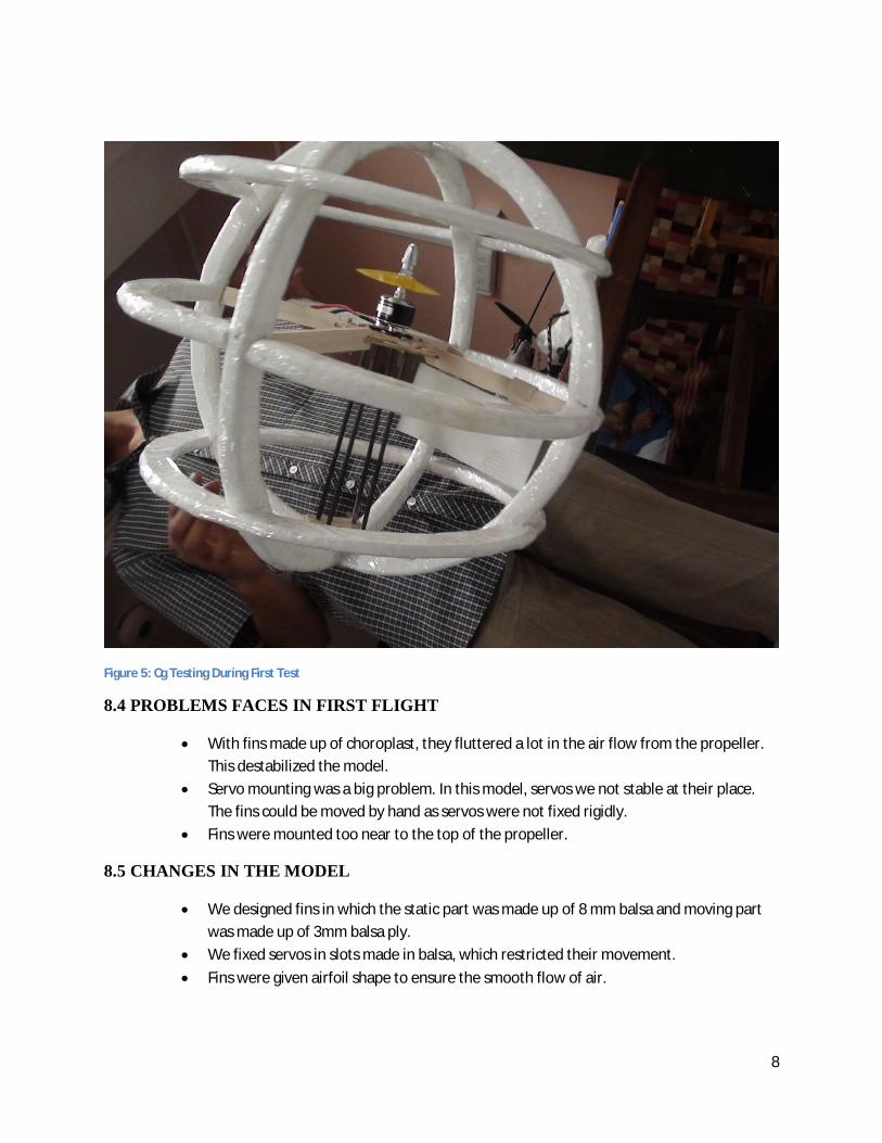
Figure 5: Cg Testing During First Test
8.4 PROBLEMS FACES IN FIRST FLIGHT
With fins made up of choroplast, they fluttered a lot in the air flow from the propeller. This destabilized the model.
Servo mounting was a big problem. In this model, servos we not stable at their place. The fins could be moved by hand as servos were not fixed rigidly.
Fins were mounted too near to the top of the propeller.
8.5 CHANGES IN THE MODEL
We designed fins in which the static part was made up of 8 mm balsa and moving part was made up of 3mm balsa ply.
We fixed servos in slots made in balsa, which restricted their movement. Fins were given airfoil shape to ensure the smooth flow of air.
9
8.6 INFERENCE
The model hovers at 70% thrust with 9×6 propeller. Also, this model is strong enough to bear all the forces.
9. SECOND TEST FLIGHT 9.1 VENUE
Rooftop of New SAC, IIT Kanpur
9.2 PURPOSE
To test if the fins are able to balance the anti-torque.
9.3 FLIGHT SET-UP
The model was tethered to ground at four equiangular points on the equator with loose ropes. This gave it rotational freedom about its central vertical axis but restricted its free movement in space.
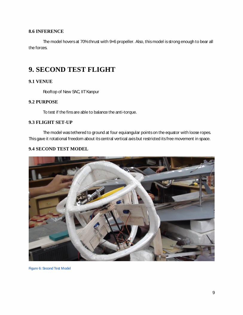
9.4 SECOND TEST MODEL
Figure 6: Second Test Model
10
9.5 PROBLEMS FACED IN SECOND FLIGHT
It was windy, and our two control surfaces were free i.e. with no servos connected. So they fluttered a lot in the wind.
9.6 CHANGES IN THE MODEL
We increased the size and changed the shape of Fins. We increased length of stators, which cancels the destabilizing torque.
9.7 INFERENCE
Once the wind stopped, control surfaces also stopped fluttering and then the model was stable. So the initial wobbling was due to the wind. Thus, our model was stable in static conditions but failed in strong winds.
10. CONCLUSION As of now, our UAV “Hawk Eye” has achieved hover stability, that is, it can hover without wobbling about its central axis. This is the first step towards making a completely autonomous remote controlled aircraft. Our next step is to work on the navigation and control system. We can either program the entire micro-processor, or can use the pre-programmed ardu-pilot and simply calibrate the controls by several test flights. We will be working on the first approach, as it offers better customization opportunities.
11. REFERENCES
1. http://www.arduino.cc/ 2. http://students.iitk.ac.in/roboclub/tutorials.php 3. http://www.ultraligero.net/Cursos/mecanica/fundamentos_de_la_mecanica_de_vuelo.pdf 4. http://www.theuav.com/ 5. http://www.mae.buffalo.edu/research/laboratories/combustionlab/Thrust%20vectoring/Thrust
%20vectoring.htm 6. http://www.airspacemag.com/flight-today/Thrust_Vectoring.html 7. http://en.wikipedia.org/wiki/Coaxial_rotors 8. http://en.wikipedia.org/wiki/Thrust_vectoring 9. http://www.aerostudents.com/files/aircraftPerformance/flightMechanics.pdf 10. http://science.howstuffworks.com/predator.htm 11. http://www.insidegnss.com/auto/janfeb08-wp.pdf 12. http://www.youtube.com/watch?v=pF0uLnMoQZA 13. http://www.youtube.com/watch?v=7mUNIvlgYKk
11
RESPONSES TO THE REVIEWERS REMARKS 1. Page no: 4
Remark: Write “Basic Idea” instead of “Basic Algorithm” Response: This is not a paper on computer science. In most of the branches of engineering, there is not much distinction between idea and algorithm. Moreover, the section describes the basic control system of the UAV. It explains the “algorithm” implemented to ensure that the UAV remains stable in flight and performs other maneuvers. Algorithm is more word and hence this change has not been included.
2. Page no: 5 Remark: Description of the skeleton of the UAV does not match figure. Response: The description included is for the unfinished model. The correct description for the finished model has been incorporated.
3. Page no: 5 Remark: Chloroplast has been mentioned as a building material for rings, which seems out of context, chloroplast being plant pigment. Response: It was an auto-correct error. Composite was replaced by chloroplast by MS-Word. The correct word has been included.
4. Page no: 6 Remark: Claim for the components being optimal should be mentioned. Response: The claims were made on the basis of several test flights. Moreover, each DC motor tabulates the thrusts it can produce with different propeller sizes. All these were used to reach the optimum level. This has now been mentioned in the paper.