university of wisconsin system solid waste · pdf fileuniversity of wisconsin system solid...
TRANSCRIPT

1
Characterization of Regenerated Cellulose for Bio-based Epoxy Fibrous Composites
May 2013
Student Investigator: Issam Qamhia Advisor: Professor Rani El-Hajjar
Department of Civil Engineering & Mechanics; Materials Science & Engineering
University of Wisconsin-Milwaukee
UNIVERSITY OF WISCONSIN SYSTEM SOLID WASTE RESEARCH PROGRAM Student Project Report

2
Introduction:
The objective of this research is to characterize regenerated and nano-cellulose fibers and their
composites with epoxy for mechanical properties, and to evaluate manufacturing techniques for these
composites. Cellulose is the most abundant natural material and is the main component of many solid
waste products of households, businesses and construction projects. Experimental and computational
fracture mechanics and strength approaches are used to suggest an optimum architecture of the
reinforcement to produce the desired mechanical properties. The resultant optimum design of the
reinforcement architecture is expected to give rise to a new method of producing high-strength, bio-based
and sustainable composites for different regenerated cellulose fibers and cellulose nano-fibers.
The results of this research are presented and published in the following conference and journal
publications:
1. Qamhia, I., El-‐Hajjar, R. F., “Processing of Nanocellulose Scaffolds for Increased Fiber ContentThermosetting Composites.” 1st International Conference on Natural Fibers, Guimarães,Portugal, 2013 June 9-‐11.
2. Qamhia, I., Shams, S. S., El-‐Hajjar, R. F., “Analytical Prediction of Elastic Properties In TriaxiallyBraided Regenerated Cellulose Composites.” 1st International Conference on Natural Fibers,Guimarães, Portugal, 2013 June 9-‐11.
3. Qamhia, I., El-‐Hajjar, R. F., “Preparation and Thermomechanical Characterization ofNanocellulose Scaffolding / Thermoset Composites,” Advancements in Fiber-‐PolymerComposites: Wood Fiber, Natural Fibers and Nanocellulose Conference; 2013 May 6-‐7;Milwaukee, WI, USA
4. El-‐Hajjar, R. F., Qamhia, I., Shams, S. S., “Analytical Characterization Of The MechanicalProperties In Triaxially Braided Regenerated Cellulose Composites,” Advancements in Fiber-‐Polymer Composites: Wood Fiber, Natural Fibers and Nanocellulose Conference; 2013 May 6-‐7;Milwaukee, WI, USA
5. Qamhia, I. I., El-‐Hajjar, R. F., “Mechanical and Thermal Properties of NanocelluloseScaffolding/Epoxy Composites Prepared by a Vacuum Assisted Heated-‐Press Approach,”. Postersession presented at: Sustainable Cities and Infrastructure. 10th Annual Sustainability Summitand Exposition; 2013 March 6-‐7; Milwaukee, WI, USA.
6. El-‐Hajjar, R. F., and Qamhia, I. I., “Modeling and Characterization of the Moisture DependentBilinear Behavior of Regenerated Cellulose Composites,” Journal of Wood Science, Accepted forPublication. 2013
3
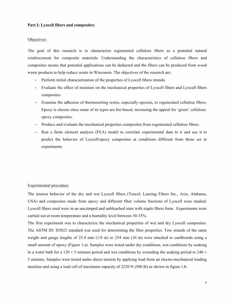
Part I: Lyocell fibers and composites:
Objectives:
The goal of this research is to characterize regenerated cellulose fibers as a potential natural
reinforcement for composite materials. Understanding the characteristics of cellulose fibers and
composites means that potential applications can be deducted and the fibers can be produced from wood
waste products to help reduce waste in Wisconsin. The objectives of the research are:
− Perform initial characterization of the properties of Lyocell fibers strands.
− Evaluate the effect of moisture on the mechanical properties of Lyocell fibers and Lyocell fibers
composites.
− Examine the adhesion of thermosetting resins, especially epoxies, to regenerated cellulose fibers.
Epoxy is chosen since some of its types are bio-based, increasing the appeal for ‘green’ cellulose-
epoxy composites.
− Produce and evaluate the mechanical properties composites from regenerated cellulose fibers.
− Run a finite element analysis (FEA) model to correlate experimental data to it and use it to
predict the behavior of Lyocell/epoxy composites at conditions different from those set in
experiments.
Experimental procedure:
The tension behavior of the dry and wet Lyocell fibers (Tencel; Lenzing Fibers Inc., Axis, Alabama,
USA) and composites made from epoxy and different fiber volume fractions of Lyocell were studied.
Lyocell fibers used were in an uncrimped and unbleached state with staple fibers form. Experiments were
carried out at room temperature and a humidity level between 30-35%.
The first experiment was to characterize the mechanical properties of wet and dry Lyocell composites.
The ASTM ID: D3822 standard was used for determining the fiber properties. Tow strands of the same
weight and gauge lengths of 25.4 mm (1.0 in) to 254 mm (10 in) were attached to cardboards using a
small amount of epoxy (Figure 1.a). Samples were tested under dry conditions, wet conditions by soaking
in a water bath for a 120 ± 5 minutes period and wet conditions by extending the soaking period to 240 ±
5 minutes. Samples were tested under direct tension by applying load from an electro-mechanical loading
machine and using a load cell of maximum capacity of 2220 N (500 lb) as shown in figure 1.b.

4
For the second experiment, composite specimens were prepared using a wet layup and resin infusion
method. The Lyocell Fibers were weighted to back-calculate the fiber volume fraction. The epoxy
chosen for this study (Super Sap 100 Epoxy; Entropy Resins Inc., Gardena, California, USA) contains
bio-renewable materials sourced as co-products or from waste streams of other industrial processes, such
as wood pulp and bio-fuels production. Samples with low fiber volume fractions (5-10%) were prepared
in a dumbbell shaped form according to the ASTM ID: D638 standard. For higher fiber volume fractions,
preparing panels using a resin-infusion and manual layup followed by degasing processes was introduced.
Panels produced using wet layup resulted in a maximum fiber volume fraction of 0.33 whereas the ones
with resin infusion resulted with a volume fraction of 0.35. Testing of composite coupons was performed
under direct tension according to the ASTM ID: D3039 standard. Strain properties were measured across
a 25.4 mm (1.0 inch) gage length in the middle of coupons by the use of an extensometer.
(a) (b) (c)
Figure I.1. (a) Lyocell tows attached to cardboards (ASTM D3822) (b) Testing of Lyocell Tows (c)
Testing of Lyocell/epoxy composite
Unit cell finite element model:
The constitutive response of the regenerated fibers was found to be dependent on the moisture condition
of the fibers. This suggests the need for a suitable analysis framework for these composites. Regenerated
Lyocell fibers possess a bilinear material behavior with elastic-plastic tendencies. Under moisture
exposure, the elastic response gradually dissipates and results in a largely plastic unrecoverable behavior.
For the purpose of this research, a multi-scale analysis approach for simulation of Lyocell/bio-based
epoxy composites that uses a representative unit cell is used. The behavior and mechanical properties of
the constituents is independently recognized. This modeling approach is implemented in a p-version finite
element analysis (p-FEA) approach. The primary advantage of this approach is the ability to check the
convergence of the solutions with increasing element order reducing the dependency on the mesh size.
StressCheck (Stress Check V9.0; ESRD, St. Louis, Missouri, USA) software was used to create and run
(b)
5
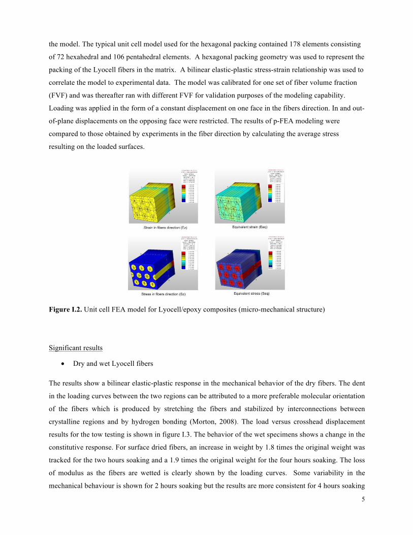
the model. The typical unit cell model used for the hexagonal packing contained 178 elements consisting
of 72 hexahedral and 106 pentahedral elements. A hexagonal packing geometry was used to represent the
packing of the Lyocell fibers in the matrix. A bilinear elastic-plastic stress-strain relationship was used to
correlate the model to experimental data. The model was calibrated for one set of fiber volume fraction
(FVF) and was thereafter ran with different FVF for validation purposes of the modeling capability.
Loading was applied in the form of a constant displacement on one face in the fibers direction. In and out-
of-plane displacements on the opposing face were restricted. The results of p-FEA modeling were
compared to those obtained by experiments in the fiber direction by calculating the average stress
resulting on the loaded surfaces.
Figure I.2. Unit cell FEA model for Lyocell/epoxy composites (micro-mechanical structure)
Significant results
• Dry and wet Lyocell fibers
The results show a bilinear elastic-plastic response in the mechanical behavior of the dry fibers. The dent
in the loading curves between the two regions can be attributed to a more preferable molecular orientation
of the fibers which is produced by stretching the fibers and stabilized by interconnections between
crystalline regions and by hydrogen bonding (Morton, 2008). The load versus crosshead displacement
results for the tow testing is shown in figure I.3. The behavior of the wet specimens shows a change in the
constitutive response. For surface dried fibers, an increase in weight by 1.8 times the original weight was
tracked for the two hours soaking and a 1.9 times the original weight for the four hours soaking. The loss
of modulus as the fibers are wetted is clearly shown by the loading curves. Some variability in the
mechanical behaviour is shown for 2 hours soaking but the results are more consistent for 4 hours soaking

6
and show a drastic loss in modulus and a non-linear behavior of the fibers. A reduction in the failure
stress accompanied by a higher strains to failure is also observed for the wet fibers compared to the dried
ones. Additionally, the knee seen in the loading curves for the dry fibers is shifted toward the (0, 0) point
of the curves as the level of moisture increases in the fibers due to the removal of the hydrogen bonds
(Morton, 2008). The behavior of the wet fibers is plastic.
Figure I.3. Load-displacement curve for dry and wet Lyocell tows showing the effect of moisture on the
behavior of the fibers.
• Lyocell/epoxy composites
Panel preparation by wet layup followed by degasing was found to produce better samples than other
examined procedures. Pilling and fibrillation are inherent in the structure of Lyocell and adds difficulties
to the manufacturing process. Using resin infusion, thinner samples with higher FVF were produced.
However, good infusion of the resin with the fibers could not be achieved for the whole panel and some
areas were not properly wetted. Equal distribution of fibers among the panel and waviness prevention
were two major challenges of the wet layup method. By using tape to stretch and fix the fibers in position,
the effect of these challenges was reduced. Degasing the samples with a vacuum pump after wet layup
also insured minimal porosity.
• Finite element model
The p-FEA model proposed was calibrated for one set of experimental values using the specimens having
a fiber content of 33%. Error analysis is performed on the results by examining the global energy norm
versus the polynomial order and degrees of freedom. The predictive properties of the stress strain graphs

7
are shown in figure I.4 superimposed with the FE calibration curve. The p-FEA model was successfully
used to capture the experimental stress-strain behavior of the composites and the FE model was calibrated
to average the differences seen in the plastic region for the samples. The results show that it is possible to
reproduce accurate results for different fiber volume fractions. Changes in the elastic and plastic modulus
of Lyocell-epoxy composites with different fiber contents is shown figure I.5. A linear change is seen
which can be attributed to the use of a bilinear stress-strain curve for Lyocell and a linear one for epoxy.
This linear mechanical behavior is expected to change with the wet composites where the non-linearity of
the Lyocell loading curve is expected to lead to nonlinearity in the stress-strain curve of the composites.
Some of the coupons with the high fiber volume fraction were tested for the effect of moisture on Lyocell
composites by soaking for two hours investigate how they compare to the model of dry Lyocell
composites. The result of these are shown in figure I.5.
Figure I.4. Experimental and FEA model results for stress-strain curves of Lyocell/epoxy composites for
different fiber volume fractions (19% and 33%).

8
Figure I.5. Experimental and FEA model results for the change in elastic and plastic moduli with fiber
volume fraction.
Part II: Cellulose nanofibers and composites:
Objectives:
The goal of this research is to lay the groundwork for using Cellulose NanoFibers (CNFs) Aerogels as
reinforcements in epoxy-based composites. This research is aimed to compliment ongoing efforts at
Forest Products Laboratory (FPL) to produce reinforcements from CNFs.
Specifically, the objectives are to:
− Perform initial investigations into the swelling and liquid flow into and through CNF scaffolds.
− Examine the adhesion of thermoset resins, especially epoxies, to CNFs.
− Investigate different fabrication techniques for CNF/epoxy composites to produce composites
with the highest possible CNF content and minimal porosity.
− Investigate the effect of the presence of cellulose on resin curing behavior.
Experimental procedure:
The material used for this study was a CNF scaffold provided by Forest Products Laboratory; Madison.
The experimental part of this research was to characterize the nanocellulose scaffolds, investigate the
wetting of the nanocellulose by different resin systems and to investigate different fabrication procedures
for the composites. Two resin systems were used to prepare composites, namely: Super Sap 100 Epoxy
(Super Sap 100 Epoxy ; Entropy Resins Inc., Gardena, California, USA) and Embed-It epoxy (Embed-
It™ Low Viscosity Epoxy; Polysciences, Inc, Warrington, Pennsylvania, USA). Composites were
prepared from the two resin systems by manual layup followed by degasing. The Samples with Super-Sap
epoxy showed very little wetting due to the high viscosity of the resin. Samples made with Embed-it
epoxy showed better wetting. Thus, Super Sap epoxy was eliminated and Embed-it epoxy was used due
to its low viscosity (65 cps). The fabrication techniques investigated were as follows:
1. Wet Layup followed by degasing
Samples in Embed-It epoxy were degased by a vacuum pump for 2 hours at 610 mm Hg (-24 in. Hg) over
a hot plate, and were cured for 16+ hours at 175 ºF. These samples showed good impregnation. Embed-It
resin-only samples were prepared as a control point. Samples prepared by this technique showed proper
wetting but resin content was very high, leading to low fiber content.
9
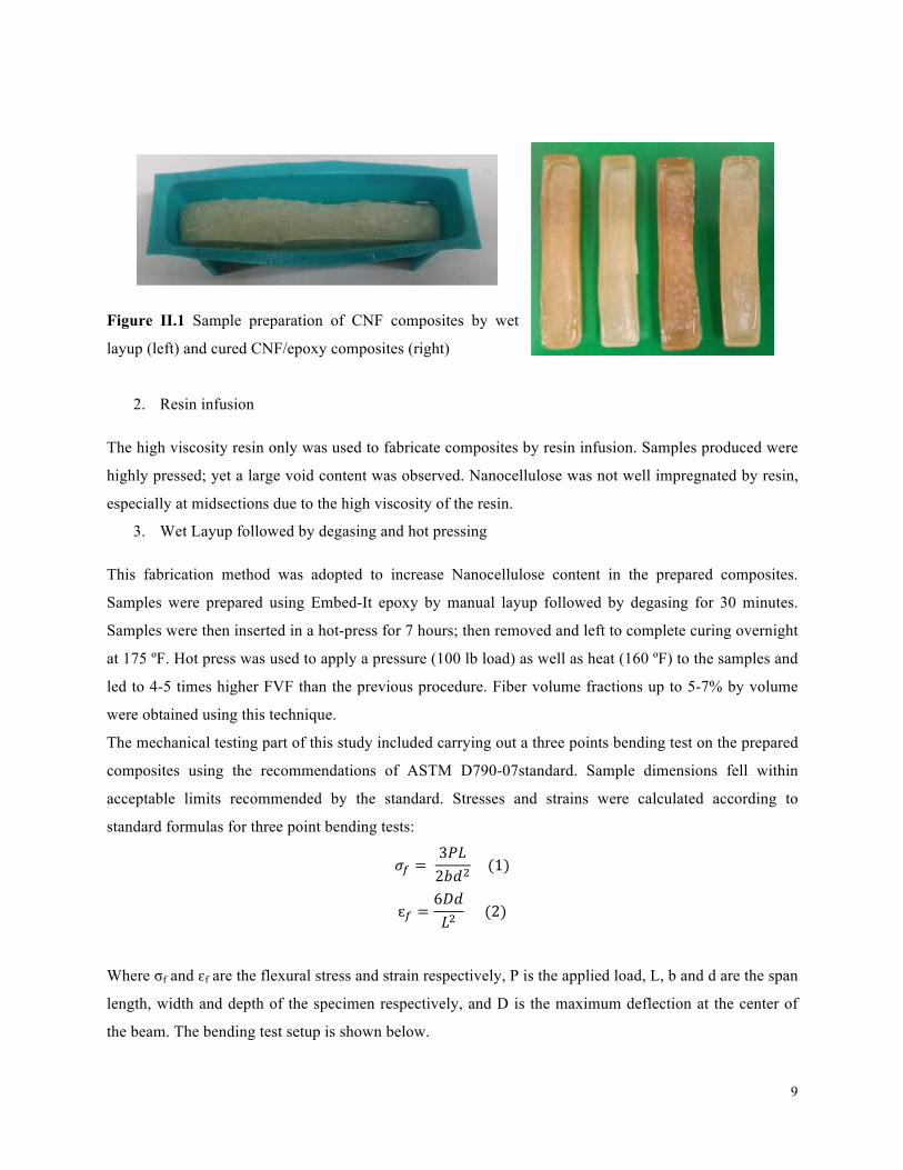
Figure II.1 Sample preparation of CNF composites by wet
layup (left) and cured CNF/epoxy composites (right)
2. Resin infusion
The high viscosity resin only was used to fabricate composites by resin infusion. Samples produced were
highly pressed; yet a large void content was observed. Nanocellulose was not well impregnated by resin,
especially at midsections due to the high viscosity of the resin.
3. Wet Layup followed by degasing and hot pressing
This fabrication method was adopted to increase Nanocellulose content in the prepared composites.
Samples were prepared using Embed-It epoxy by manual layup followed by degasing for 30 minutes.
Samples were then inserted in a hot-press for 7 hours; then removed and left to complete curing overnight
at 175 ºF. Hot press was used to apply a pressure (100 lb load) as well as heat (160 ºF) to the samples and
led to 4-5 times higher FVF than the previous procedure. Fiber volume fractions up to 5-7% by volume
were obtained using this technique.
The mechanical testing part of this study included carrying out a three points bending test on the prepared
composites using the recommendations of ASTM D790-07standard. Sample dimensions fell within
acceptable limits recommended by the standard. Stresses and strains were calculated according to
standard formulas for three point bending tests:
!! = 3!"2!!!
(1)
ɛ! =6!"!!
(2)
Where σf and ɛf are the flexural stress and strain respectively, P is the applied load, L, b and d are the span
length, width and depth of the specimen respectively, and D is the maximum deflection at the center of
the beam. The bending test setup is shown below.

10
Figure II.2 Sample preparation of CNF composites by hot pressing
(left) , an image of the hot press (center) and the three points bending
test setup (right).
Other Experiments carried out to characterize the thermal behavior of the composites upon heating were
Differential scanning calorimetry (DSC) and Thermogravimetric analysis (TGA). DSC is a thermo-
analytical technique in which the difference in the amount of heat required to increase the temperature of
a sample and reference is measured as a function of temperature. Round samples of around 25mg in
weight were cored out from CNF/epoxy composites and pure Embed-IT epoxy resin samples for testing.
The main aim of the test was to see if cellulose is changing the glass transition temperature of the resin.
However, more important information about decomposition of the composites, and curing were obtained.
TGA is a type of testing performed on samples that determines changes in weight in relation to a
temperature program in a controlled atmosphere. Such analysis relies on a high degree of precision in
three measurements: weight, temperature, and temperature change. The main use for this technique was to
find the decomposition temperature of CNF/epoxy composites. Experiments were carried out in Argonne
gas to prevent oxidation.
Significant Results:
Transparency and density analysis reveal that the Super-Sap epoxy resin did not infuse well with the
aerogels for both resin infusion and wet layup techniques. Resin infusion produced better results but the
percentage of voids was still high. By the use of low viscosity epoxy resin (Embed-It), the curing time for
manual layup was relatively high (around 16-24 hours), but good results of infusion were obtained. The
use of the hot press enabled obtaining higher cellulose content in the composites (up to 7.5% by volume)
and ensured minimal porosity. Samples prepared by this technique showed higher elastic modulus in
addition to higher strength to failure when compared to the pure resin and to lower enforcement levels of
cellulose prepared by manual layup.

11
The Embed-It resin was found to be sensitive to curing temperature and curing cycles. When the hot
pressing preparation method was used, the mechanical properties of the pure resin samples and the nano-
cellulose composites were improved in terms of modulus and failure stress. Results for samples prepared
by this technique shows that the nano-cellulose is not significantly improving the mechanical properties
(figure II.3). A 15% average increase in modulus is observed for reinforcement levels of 5-7.5%.
However, nano-cellulose samples are more brittle and fail at a lower stress. DSC results reveal the
importance of proper resin curing to the properties of the composites. No exothermic peaks are observed
for samples prepared by hot pressing indicating that the resin is well cured. Glass transition temperature
(Tg) for the pure resin was found to be around 265 ºC. When nanocellulose is added, data on Tg is
inconclusive. TGA results indicate that the decomposition temperature of cellulose/epoxy composites is
270 ºC; where a noticeable mass drop is observed (figure II.4).
Figure II.3 Flexural stress-strain behavior of CNF/epoxy and pure epoxy composites

12
Figure II.4 Sample preparation of CNF composites by wet layup (left) and cured CNF/epoxy composites
(right)
Part III: BioMid fibers and composites:
Objectives:
The goal of this research is to characterize BioMid regenerated cellulose fibers composites for potential
use as naturally reinforced composites in industries. Understanding the mechanical behavior of these
composites means that potential applications can be deducted and the fibers can be produced from wood
waste products to help reduce waste in Wisconsin. The objectives of the research are:
– Examine different test methods (Mechanical, Acoustic Emission) for testing regenerated cellulose
fiber composites.
– Evaluate notched and un-notched test specimens for determining the mechanical behavior of the
Regenerated Cellulose Fibers/Bio-Epoxy specimens.
– Investigate the applicability of a proposed Modified Classical Lamination Plate Theory Model to
capture the mechanical properties relating them to the undulations in the bias yarns and fiber
content.
Experimental procedure:
A triaxially braided Regenerated cellulose BioMid fiber system with [-60, 0, 60] fiber orientation was
used for reinforcement in test specimens. A&P Technology, OH performed the braiding of the materials
used in this study. Fiber architecture is produced by having the bias yarns alternating two over and two
under the axial yarns. The epoxy used in this study is a Super Sap 100/1000 (Entropy Bio-Resins,
Gardena, California, USA). The resin also has a total calculated biomass of 50%. The actual fiber volume
fraction of the composite is determined by using the volume measurements of the matrix and fiber
constituents, resulting in an average fiber volume fraction of 0.60 with a sample standard deviation of
0.02. The spacing between the bias yarns was at 26 mm, and between the axial yarns the center-to-center
spacing was 5.2 mm. The axial bundle would fill a space of approximately 2.5 mm in width between the
bias yarns.

13
Figure III.1 Braided BioMid sample showing yarns orientation
For the early trials, a wet layup technique was used to prepare the composites, but the fibers weren’t fully
infused, especially the axial yarns. The early trials of resin infusion produced medium levels of porosity, a
modification of the technique was implemented; in which silicon connectors were inserted inside the
vacuum bag and the pipes were attached to them and insulated with tape from outside the bag. With this
modification, the levels of porosity reduced drastically. The panels were infused under room temperature
conditions. BioMid fibers were stored at room temperature and a humidity level of 30%. Resin infusion
was carried out at room temperature and a humidity level of 30%. Panels were cut into 305 mm long by
38 mm wide coupons in transverse and longitudinal directions. Some panels were also cut into 152 mm
by 76mm wide samples. For these samples, a 19mm notch was cut on both sides of the sample towards
the middle. It is difficult to obtain reliable strength properties due to failure mode inconsistencies.
Notched specimens are more suited to strength measurements because all bias fiber tows are gripped.
Notched samples are also easy to fabricate and are expected to generate higher measured loads.
The elastic properties were obtained by testing the specimens in tension according to ASTM ID: D3039.
Standard for tensile properties of polymer reinforced fiber composites. The experiments were performed
in a displacement-controlled mode at a displacement rate of 1.3 mm/min.

14
(a)
(b)
Figure III.2 (a) preparation of BioMid/epoxy composites by resin infusion (b) tensile testing of notched
and un-notched samples.
For one longitudinal coupon and one transverse coupon, simultaneous mechanical testing, and acoustic
emission (AE) tests were carried out. Acoustic emission was used to investigate damage initiation and
damage propagation through the energy bursts levels of events and the timing of these events and relating
these to changes in the loading curve obtained by mechanical testing. A Physical Acoustics WS-alpha
transducer was used for measuring the AE signals. The sensor has an operating frequency of 100-1000
kHz with a 63.74dB peak sensitivity occurring at 523.23 kHz. In order to improve the quality of the
captured signals; a pre-amplifier coupled with a bandpass filter adjusted to pass frequencies in the range
of 10-1200 kHz was used. A Mistras 2001 data acquisition system was used for recording the data,
including waveforms.
Analytical model:
An analytical model was used to correlate experimental results for mechanical properties and provide a
solution to determine the sensitivity of the braided materials to braiding properties such as crimp angle
and bias yarns angles as well as the composites properties such as fiber content. A discrete 3-layer
analytical model was evaluated for this purpose. The analytical model uses a representative volume
element (RVE) or a representative unit cell to predict the macroscopic properties of triaxial composites
from constituent microscopic material properties. The model presents yarns architecture as a total
equivalent stiffness matrix of the triaxially braided composite in a unit cell. El-Hajjar et al. (2013)
examined various analytical methods and found consistent results with experiments on glass fibers using
this approach. The global stiffness of the composites is given as (Shokrieh and Mazloomi, 2010):
0 0[ ] [ ] [ ] [ ]RUCglobal global globalC t C t C t Cθ θ θ θ+ + − −= + + (3)
where t θ+ , t θ− and 0t are the thickness of each layer to the thickness of the laminate. In this research we
use the actual thickness values obtained from microstructural examinations of the cross sections of the
prepared composites as inputs for the model.
Significant Results:

15
The stress versus strain curves for longitudinal and transverse specimens loaded in tension shows that are
shown in figures III.3 and III.4. Two distinct regions can be identified for the stress-strain curve in which
the first is linear elastic and the second is the region with a lower stiffness. The loading properties are
similar to other regenerated cellulose composites, eg. Lyocell/epoxy composites (El-Hajjar and Qamhia
2013). The loading behavior and modeling of Lyocell composites was discussed in part I. The results of
cumulative acoustic emissions (figure III.5) show that the initiation of damage for transverse specimens
starts at a much lower stress level compared to the early emissions observed in the longitudinal
specimens. The initial emissions are most likely attributed to the matrix cracking. Higher energy
emissions before failure are observed for the longitudinal specimens where the final cumulative energy at
failure is 35% higher. The reason for this is thought to be associated with the fracture of the axial fibers
oriented in the direction of loading. The incidence of high acoustic emissions can be used as an indication
of the point of detrimental irreversible damage. For the fracture study, the analysis of the data is still in
progress and will be assessed in future work.
Figure III.3 Stress versus strain plots of BioMid/epoxy quasi-isotropic composites (longitudinal)
16
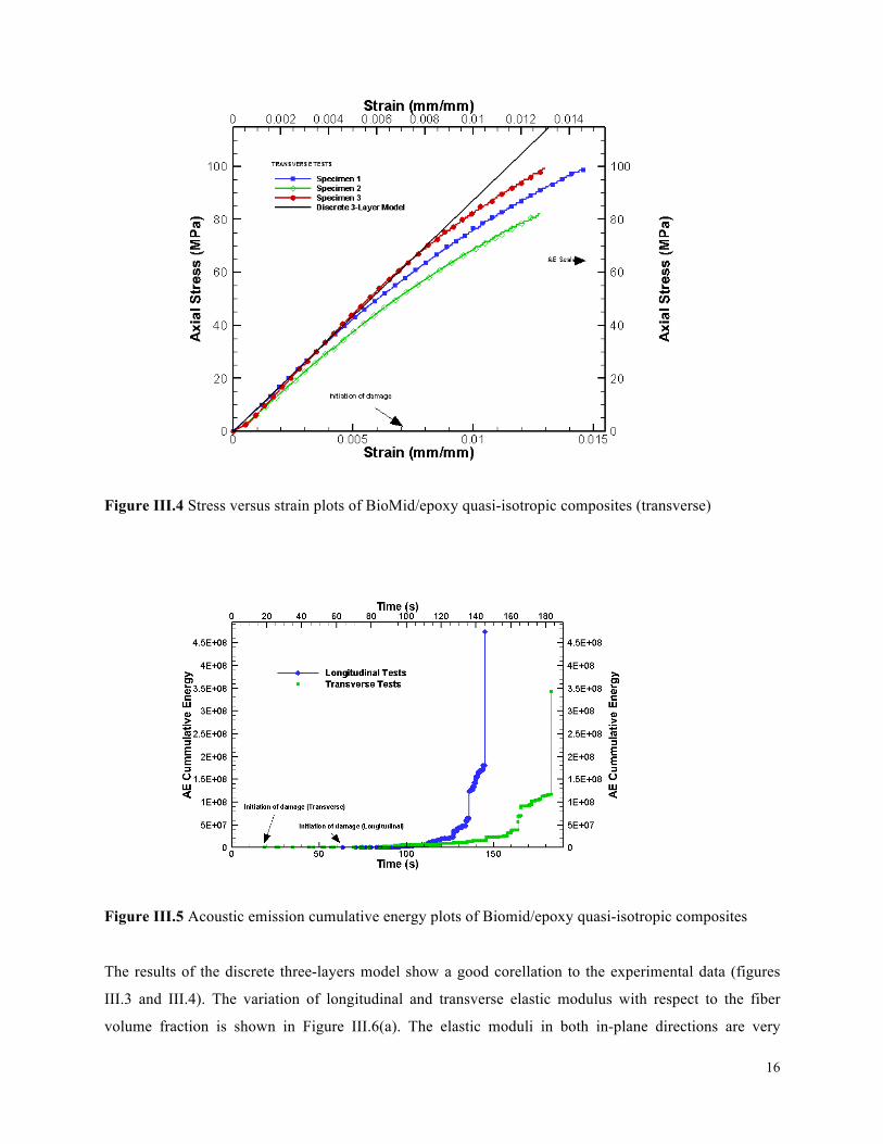
Figure III.4 Stress versus strain plots of BioMid/epoxy quasi-isotropic composites (transverse)
Figure III.5 Acoustic emission cumulative energy plots of Biomid/epoxy quasi-isotropic composites
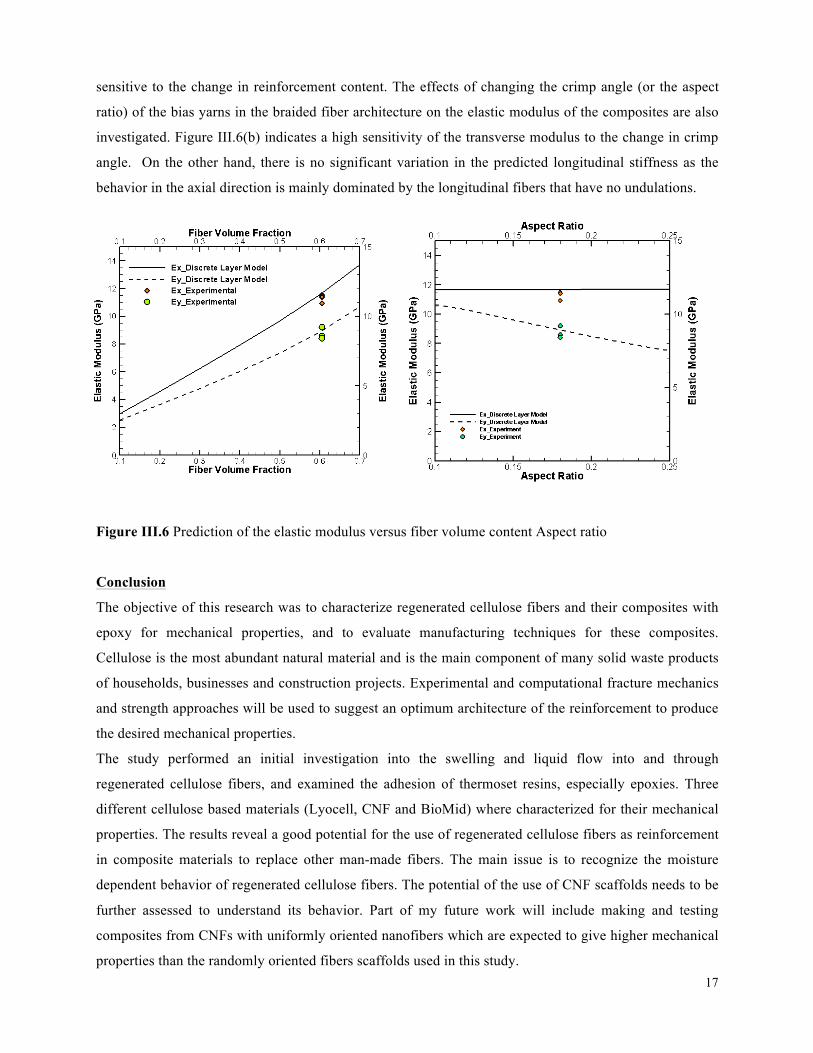
The results of the discrete three-layers model show a good corellation to the experimental data (figures
III.3 and III.4). The variation of longitudinal and transverse elastic modulus with respect to the fiber
volume fraction is shown in Figure III.6(a). The elastic moduli in both in-plane directions are very
17
sensitive to the change in reinforcement content. The effects of changing the crimp angle (or the aspect
ratio) of the bias yarns in the braided fiber architecture on the elastic modulus of the composites are also
investigated. Figure III.6(b) indicates a high sensitivity of the transverse modulus to the change in crimp
angle. On the other hand, there is no significant variation in the predicted longitudinal stiffness as the
behavior in the axial direction is mainly dominated by the longitudinal fibers that have no undulations.
Figure III.6 Prediction of the elastic modulus versus fiber volume content Aspect ratio
Conclusion
The objective of this research was to characterize regenerated cellulose fibers and their composites with
epoxy for mechanical properties, and to evaluate manufacturing techniques for these composites.
Cellulose is the most abundant natural material and is the main component of many solid waste products
of households, businesses and construction projects. Experimental and computational fracture mechanics
and strength approaches will be used to suggest an optimum architecture of the reinforcement to produce
the desired mechanical properties.
The study performed an initial investigation into the swelling and liquid flow into and through
regenerated cellulose fibers, and examined the adhesion of thermoset resins, especially epoxies. Three
different cellulose based materials (Lyocell, CNF and BioMid) where characterized for their mechanical
properties. The results reveal a good potential for the use of regenerated cellulose fibers as reinforcement
in composite materials to replace other man-made fibers. The main issue is to recognize the moisture
dependent behavior of regenerated cellulose fibers. The potential of the use of CNF scaffolds needs to be
further assessed to understand its behavior. Part of my future work will include making and testing
composites from CNFs with uniformly oriented nanofibers which are expected to give higher mechanical
properties than the randomly oriented fibers scaffolds used in this study.

18
References:
– El-Hajjar, R.F. Shams, S.S. and Kehrl, D.J. Closed form solutions for predicting the elastic
behavior of quasi-isotropic triaxially braided composites. Composite Structures, 2013. In press.
– El-Hajjar, R.F. and Qamhia, I. I., “Modeling and characterization of the moisture-dependent
bilinear behavior of regenerated cellulose composites,” Journal of Wood Science, 2013. In press.
– Morton, W.H., J, 2008. Physical properties of textile fibres, 4 ed. Woodhead Publishing.
Mottershead, B., Eichhorn, S.J., 2007. Deformation micromechanics of model regenerated
cellulose
– Shokrieh M.M., Mazloomi M.S. An analytical method for calculating stiffness of two-
dimensional tri-axial braided composites. Composite Structures. 2010;92:2901-5.