university of washington computer science and engineering ii · university of washington computer...
TRANSCRIPT

UNIVERSITY OF WASHINGTON COMPUTER SCIENCE AND ENGINEERING IIEARLY DESIGN GUIDANCE SUBMITTAL
ADDRESS: 3800 E. STEVENS WAY NE, SEATTLE WADCI PROJECT NO.: 6518797DCI LAND USE NO.: 3023786


TABLE OF CONTENTS
PROJECT OVERVIEW
CONTEXT ANALYSIS
EXISTING SITE CONDITIONS
PRIORITY DESIGN GUIDELINES
ARCHITECTURAL CONCEPT
1
2
3
4
5
PROJECT ADDRESS
DCI PROJECT NO.
DCI LAND USE NO.
PROJECT TEAM
3800 E. Stevens Way NESeattle, WA 98195
6518797
3023786
OWNERUniversity of WashingtonCapital Projects OfficeContact: Kurtis Jensen, Project ManagerPhone: 206.685.3704Email: [email protected]
PERMIT CONSULTANTPermit Consultants NWContact: Jon O’HarePhone: 253.839.4853Email: [email protected]
ARCHITECTLMN Architects801 Second Avenue, Suite 501Seattle, WA 98104Contact: Julie AdamsPhone: 206.682.3460Email: [email protected]


LMN + OLIN PROJECT # 6518797 / EARLY DESIGN GUIDANCE / 04-13–2016 1
1PROJECTOVERVIEW
5ARCHITECTURAL CONCEPT
3EXISTING SITE CONDITIONS
2CONTEXTANALYSIS
4PRIORITY DESIGN GUIDELINES
1 Project Overview
Existing SiteComputer Science & Engineering II
Project Goals and Program
IntroductionThe University of Washington Computer Science and Engineering (CSE) program ranks among the top ten programs in the nation, both at the graduate and undergraduate levels. The program is engaged in a broad range of research and interdisciplinary initiatives that produce far-reaching educational and economic benefits to the university, region and state. The program is currently largely housed in the Paul G. Allen Center for Computer Science & Engineering, which opened in 2003 and quickly became a model for new computer science buildings across the nation.
Due to the success of the CSE’s educational and research initiatives, the amount of space in the Allen Center is now substantially short of current program needs; the space deficiency becomes more critically acute when considering the consistent rate of program growth. The department has grown significantly at every level (undergraduate students, graduate students, faculty, staff, post-doctorate, industry partners, etc.) to meet the high demand in the region for CSE graduates and research.
New program spaces seek to complement and enhance the existing Allen Center by providing functions that are either insufficient or non-existent in the Allen Center. It will include space to increase both degree production and tenure faculty positions. In addition to new research and faculty office space to accommodate growth, new classrooms and an events space will be designed to be shared with the existing facility. It will become a home to undergraduate students studying in the department, supported by an undergraduate commons, workrooms, advising offices and instructional space. The overall program is categorized into seven groups: classroom, undergraduate, graduate, public shared, office, administrative, and building support. Proposed gross square footage (GSF) is 136,000 square feet.

2 LMN + OLIN PROJECT # 6518797 / EARLY DESIGN GUIDANCE / 04–13–2016
1PROJECTOVERVIEW
5ARCHITECTURAL CONCEPT
3EXISTING SITE CONDITIONS
2CONTEXTANALYSIS
4PRIORITY DESIGN GUIDELINES
Project Goals
Create a Welcoming EnvironmentProvide a warm, welcoming, and people-centered environment in which a diverse student, faculty, and staff population will want to learn, work and interact.
Create a Unified Complex for Computer Science & EngineeringThe CSE architecture and site design should engage the Allen Center to clearly establish a unified research and education complex that enhances the CSE collegial and collaborative culture. The new CSE building is an extension of the Allen Center – both programmatically and perceptually; that is, spaces in CSE will complement rather than duplicate spaces in the Allen Center. Each building should have desirable facilities so as to draw people back and forth to maximize interaction and collaboration. A physical connection between the two buildings is highly desired. However, with or without such a connection, the design should support complementary functionality and easy, direct movement between the two buildings. An entrance plaza should be designed as an extension of the existing Allen Center Plaza, enhancing the sense of connectivity of these two facilities, while also providing a welcoming sense of entry to the adjacent engineering facilities.
Provide Qualitative ParityWhile the design and finishes need not be the same as the Allen Center, the architecture should be of equal quality, attractiveness, and desirability. Neither building should be preferable over the other. Faculty and staff offices should be equivalent in terms of size, function, natural light, etc. The flexibility to reorganize faculty, staff and student locations across the two buildings as needs change without negatively impacting the culture or day or day operations is highly important in this rapidly changing field.
Foster Collaboration Among Faculty, Students and StaffThe building should facilitate teaching, learning, and research. It should promote collaboration and serendipitous interactions across faculty, students, staff and the entire CSE community. All members of
the CSE community are involved in a broad range of department activities; the building should provide spaces where all department members can learn, discover, meet and interact. This connectivity and community should extend from the new building to the Paul G. Allen Center through symbolic, gestural and physical connections to create a unified, single program.
Enhance the Sense of Community for CSE UndergraduatesUndergraduate spaces should be desirable and cultivate a feeling of belonging for the CSE undergraduate community. Classrooms should provide an intimate environment for teachers to interact with students.
Provide Flexible Instructional and Research SpacesResearch labs, collaboration spaces, and classrooms should be flexible and modular to fill a variety of needs, as well as adapt to program changes over time. All spaces should provide a comfortable environment for their occupants in each configuration.
Maximize Natural DaylightThe building should be designed to maximize natural daylight in all occupied spaces, with operable windows for natural ventilation where appropriate.
Create Multiple Secure ZonesThe building should be designed to provide independent security zones with access-control in accordance with programmatic organization.
Enhance Campus Connections & LandscapeThe building should be approachable from all sides relative to the public realm and enhance existing campus connections while making pedestrian routes more universally accessible. Landscaping on the site should complement the surrounding campus environment and provide a natural setting for informal interactions. The building should support CSE’s large bicycle-friendly commuting culture with safe, secure bicycle storage at interior and exterior locations. The building should respect and enhance the primary views from adjacent facilities of Lake Washington and the Cascade mountain range in relation to its height and orientation. It should also take advantage of the same views, with an emphasis on the public spaces.
Landscape DesignThe landscape site design at the University of Washington’s Computer Science and Engineering II (CSE II) building aims to build strong connections between the campus landscape adjacent to the Paul G. Allen Center and to enhance existing pedestrian through-circulation across the site. Currently, the site is the location for the More Hall Annex, an unused structure that once housed equipment for the campus nuclear physics program. Upon demolition, the site will become the future home to a new computer science and engineering building.
Essential to the landscape design is an understanding of Steven’s Way as a significant circulatory route and an important shared pedestrian corridor. Steven’s Way is an important ring road that outlines the greater portion of the University of Washington central campus inclusive of this project. Despite its co-location with the major pedestrian corridors of campus, Stevens Way is not yet a pedestrian friendly corridor and pedestrian crossings are limited or compromised at some intersections which would benefit from improved delineation of crossings and traffic calming.
The overall site concept is a shared plaza across Steven’s Way, with terraces connected to buildings that provide perches for people to gather, socialize, eat and drink. In essence, this transformation from road to celebrated plaza creates an active rapport between the Allen Center and CSE II, while establishing a new node along Steven’s Way.
Also essential to the landscape design is the relationship between the campus environment and the natural forest condition of the Pacific Northwest. Preservation and enhancement of this forest quality via the replanting of trees on site is integral to supporting this relationship. As one moves down slope on the north side there is grove space that is accessible via an ADA ramp and stairs that complements the lower half of the building, from there a series of stairs navigate a proposed treed slope with soft understory vegetation connecting to a future HEC-Ed 2 Bridge.

LMN + OLIN PROJECT # 6518797 / EARLY DESIGN GUIDANCE / 04-13–2016 3
1PROJECTOVERVIEW
5ARCHITECTURAL CONCEPT
3EXISTING SITE CONDITIONS
2CONTEXTANALYSIS
4PRIORITY DESIGN GUIDELINES
2 Context Analysis
1 2
34
56
7
8
9

4 LMN + OLIN PROJECT # 6518797 / EARLY DESIGN GUIDANCE / 04–13–2016
1PROJECTOVERVIEW
5ARCHITECTURAL CONCEPT
3EXISTING SITE CONDITIONS
2CONTEXTANALYSIS
4PRIORITY DESIGN GUIDELINES
StreetscapeJefferson Rd - Google Maps https://www.google.com/maps/@47.652579,-122.3042057,3a,75y,293.37h,93.16t/data=!3m6!1...
1 of 1 4/8/2016 3:28 PM
Jefferson Rd - Google Maps https://www.google.com/maps/@47.6533968,-122.3040732,3a,75y,273.52h,93.35t/data=!3m6!...
1 of 1 4/8/2016 3:30 PM
Jefferson Rd - Google Maps https://www.google.com/maps/@47.6530734,-122.3041313,3a,75y,275.04h,90.79t/data=!3m6!...
1 of 1 4/8/2016 3:29 PM
Jefferson Rd - Google Maps https://www.google.com/maps/@47.6526911,-122.3042066,3a,75y,293.69h,92.07t/data=!3m6!...
1 of 1 4/8/2016 3:28 PM
Jefferson Road Looking North Jefferson Rd - Google Maps https://www.google.com/maps/@47.652579,-122.3042057,3a,75y,106.06h,86.08t/data=!3m6!1...
1 of 1 4/8/2016 3:33 PM
Jefferson Rd - Google Maps https://www.google.com/maps/@47.6528087,-122.3041826,3a,75y,98.37h,88.88t/data=!3m6!1...
1 of 1 4/8/2016 3:32 PM
Jefferson Rd - Google Maps https://www.google.com/maps/@47.6530734,-122.3041313,3a,75y,96.79h,87.92t/data=!3m6!1...
1 of 1 4/8/2016 3:32 PM
Jefferson Rd - Google Maps https://www.google.com/maps/@47.6532978,-122.3040805,3a,75y,91.55h,87.1t/data=!3m6!1e...
1 of 1 4/8/2016 3:31 PM
Jefferson Road Looking SouthMason Rd - Google Maps https://www.google.com/maps/@47.6517377,-122.3041883,3a,75y,313.31h,93.35t/data=!3m6!... Mason Rd - Google Maps https://www.google.com/maps/@47.6524199,-122.3039141,3a,75y,286.16h,85t/data=!3m6!1e...Mason Rd - Google Maps https://www.google.com/maps/@47.6521534,-122.3039611,3a,75y,270.69h,87.32t/data=!3m6!...Mason Rd - Google Maps https://www.google.com/maps/@47.6519794,-122.3039801,3a,75y,288.05h,85.7t/data=!3m6!1...
Mason Road Looking North

LMN + OLIN PROJECT # 6518797 / EARLY DESIGN GUIDANCE / 04-13–2016 5
1PROJECTOVERVIEW
5ARCHITECTURAL CONCEPT
3EXISTING SITE CONDITIONS
2CONTEXTANALYSIS
4PRIORITY DESIGN GUIDELINES
Mason Rd - Google Maps https://www.google.com/maps/@47.6524199,-122.3039141,3a,75y,106.41h,86.85t/data=!3m6!...
1 of 1 4/8/2016 3:34 PM
Mason Rd - Google Maps https://www.google.com/maps/@47.6519794,-122.3039801,3a,75y,106.22h,87.01t/data=!3m6!...
1 of 1 4/8/2016 3:35 PM
Mason Rd - Google Maps https://www.google.com/maps/@47.6521534,-122.3039611,3a,75y,92.69h,84.52t/data=!3m6!1...
1 of 1 4/8/2016 3:34 PM
Mason Rd - Google Maps https://www.google.com/maps/@47.6523157,-122.3039408,3a,75y,100.43h,86.3t/data=!3m6!1...
1 of 1 4/8/2016 3:34 PM
Mason Road Looking South
Stevens Way Looking North
Stevens Way Looking South

6 LMN + OLIN PROJECT # 6518797 / EARLY DESIGN GUIDANCE / 04–13–2016
1PROJECTOVERVIEW
5ARCHITECTURAL CONCEPT
3EXISTING SITE CONDITIONS
2CONTEXTANALYSIS
4PRIORITY DESIGN GUIDELINES
Campus Master Plan
104 University of Washington Master Plan -- Seattle Campus: Development ProgramSITES 16C, 18C, 19C, 20C
Figure IV-66
Connect open spacewith Forest ResourcesCourtyard
Maintain pedestrianlink to Burke-Gilmanand Husky Stadium
Develop as majorpedestrian accessbetween East andCentral Campuses
Maintain viewsto East
18CEnhance views from thesite and visibility of thesite
20CPreserve existing trees
18C
16C
20C
ILLUSTRATIVE DEVELOPMENT AREA C-5
16C(potential undergroundbuilding)
S
S
S
e
e
e
e
19C(underground)Underground parkingwith open space on topof deck
19C
Improve courtyardalong Stevens Way
BLOEDEL
WINKENW
ERDER
ANDERSON
MORE HALL
RAINIER VISTA
ROBERTS HALL
STEVENS WAY
eP
Potential Building Envelope
Area of Influence
Parking
Service
Entry
Legend
Enhanced Pedestrian Circulation
S
BLOEDEL
LMN + OLIN PROJECT # 6518797 / EARLY DESIGN GUIDANCE / 04-13–2016 7
1PROJECTOVERVIEW
5ARCHITECTURAL CONCEPT
3EXISTING SITE CONDITIONS
2CONTEXTANALYSIS
4PRIORITY DESIGN GUIDELINES
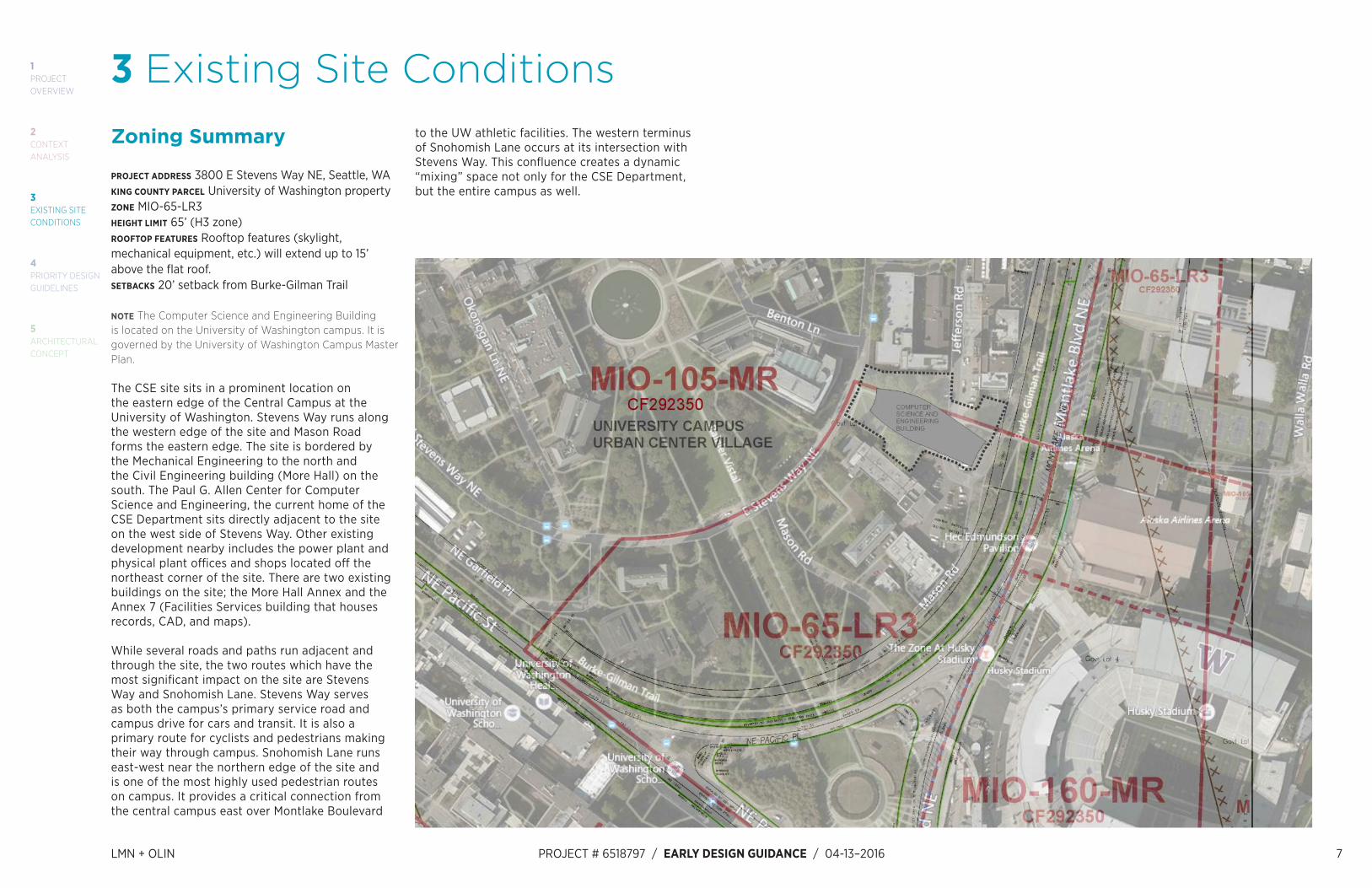
3 Existing Site Conditionsto the UW athletic facilities. The western terminus of Snohomish Lane occurs at its intersection with Stevens Way. This confluence creates a dynamic “mixing” space not only for the CSE Department, but the entire campus as well.
Zoning Summary
PROJECT ADDRESS 3800 E Stevens Way NE, Seattle, WAKING COUNTY PARCEL University of Washington propertyZONE MIO-65-LR3HEIGHT LIMIT 65’ (H3 zone)ROOFTOP FEATURES Rooftop features (skylight, mechanical equipment, etc.) will extend up to 15’ above the flat roof. SETBACKS 20’ setback from Burke-Gilman Trail
NOTE The Computer Science and Engineering Building is located on the University of Washington campus. It is governed by the University of Washington Campus Master Plan.
The CSE site sits in a prominent location on the eastern edge of the Central Campus at the University of Washington. Stevens Way runs along the western edge of the site and Mason Road forms the eastern edge. The site is bordered by the Mechanical Engineering to the north and the Civil Engineering building (More Hall) on the south. The Paul G. Allen Center for Computer Science and Engineering, the current home of the CSE Department sits directly adjacent to the site on the west side of Stevens Way. Other existing development nearby includes the power plant and physical plant offices and shops located off the northeast corner of the site. There are two existing buildings on the site; the More Hall Annex and the Annex 7 (Facilities Services building that houses records, CAD, and maps).
While several roads and paths run adjacent and through the site, the two routes which have the most significant impact on the site are Stevens Way and Snohomish Lane. Stevens Way serves as both the campus’s primary service road and campus drive for cars and transit. It is also a primary route for cyclists and pedestrians making their way through campus. Snohomish Lane runs east-west near the northern edge of the site and is one of the most highly used pedestrian routes on campus. It provides a critical connection from the central campus east over Montlake Boulevard

8 LMN + OLIN PROJECT # 6518797 / EARLY DESIGN GUIDANCE / 04–13–2016
1PROJECTOVERVIEW
5ARCHITECTURAL CONCEPT
3EXISTING SITE CONDITIONS
2CONTEXTANALYSIS
4PRIORITY DESIGN GUIDELINES
Solar Study
N
S
EW
June 21
9 AM 3 PM12 PM
September 21
9 AM 3 PM12 PM
December 21
9 AM 3 PM12 PM

LMN + OLIN PROJECT # 6518797 / EARLY DESIGN GUIDANCE / 04-13–2016 9
1PROJECTOVERVIEW
5ARCHITECTURAL CONCEPT
3EXISTING SITE CONDITIONS
2CONTEXTANALYSIS
4PRIORITY DESIGN GUIDELINES
Proposed Circulation

10 LMN + OLIN PROJECT # 6518797 / EARLY DESIGN GUIDANCE / 04–13–2016
1PROJECTOVERVIEW
5ARCHITECTURAL CONCEPT
3EXISTING SITE CONDITIONS
2CONTEXTANALYSIS
4PRIORITY DESIGN GUIDELINES
Open Spaces

LMN + OLIN PROJECT # 6518797 / EARLY DESIGN GUIDANCE / 04-13–2016 11
1PROJECTOVERVIEW
5ARCHITECTURAL CONCEPT
3EXISTING SITE CONDITIONS
2CONTEXTANALYSIS
4PRIORITY DESIGN GUIDELINES
Campus Connections

12 LMN + OLIN PROJECT # 6518797 / EARLY DESIGN GUIDANCE / 04–13–2016

LMN + OLIN PROJECT # 6518797 / EARLY DESIGN GUIDANCE / 04-13–2016 13
1PROJECTOVERVIEW
5ARCHITECTURAL CONCEPT
3EXISTING SITE CONDITIONS
2CONTEXTANALYSIS
4PRIORITY DESIGN GUIDELINES
4 Priority Design Guidelines
Response to Design Guidelines
CS1 Natural Systems and Site Features
Use natural systems and features of the site and its surroundings as a starting point for project design.
A. ENERGY USE1. ENERGY CHOICES At the earliest phase of project development, examine how energy choices may influence building form, siting, and orientation, and factor in the findings when making siting and design decisions.
RESPONSEThe University of Washington is committed to environmental stewardship that supports sustainability in not just research and education, but also in how it constructs and manages facilities and resources. The CSE project looked at a series of daylighting studies to inform program orientation, view angles to determine height and existing site softscape, topography and site circulation to inform building perimeter shaping and program allocation. The project is also investigating building systems and materials that will support the institutional energy performance goals of the UW. The project intends to achieve LEED Silver.
B. SUNLIGHT AND NATURAL VENTILATION1. SUN AND WIND Take advantage of solar exposure and natural ventilation available onsite where possible. Use local wind patterns and solar gain as a means of reducing the need for mechanical ventilation and heating where possible.
RESPONSEThe project will feature a dedicated outdoor air system (DOAS) system and operable windows in private offices and instructional spaces, providing natural ventilation for occupant comfort and fresh air. The orientation of the roof provides a great opportunity for solar power generation, and 40% of roof area has been designated as a solar zone for future photovoltaic (PV) panel installation.
2. DAYLIGHTING AND SHADING Maximize daylight for interior and exterior spaces and minimize shading on adjacent sites through the placement and/or design of structures on the site.
RESPONSEAll perimeter spaces will have access to ample daylight and views via generously sized windows. A skylight above the atrium will provide natural daylight, views of the sky and a sense of time for interior spaces without access to an exterior wall.
3. MANAGING SOLAR GAIN Manage direct sunlight falling on south and west facing facades through shading devices and existing or newly planted trees.
RESPONSEBased on solar gain studies completed for all facades of the building, varying types of glazing will be provided to ensure the appropriate U-Factor and Solar Heat Gain Coefficient for each exposure. Additionally, sun shade devices and building overhangs integrated into the building massing for these same elevations are under consideration. An existing stand of trees (deciduous and coniferous) is proposed to remain at the south elevation, and will provide significant shading at this location.
C. TOPOGRAPHY1. LAND FORM Use the natural topography and/or other desirable land forms or features to inform the project design.
RESPONSEExisting site topography was considered in the distribution of program area over the site. Primary public areas are clustered at main entries located on Stevens Way and Jefferson Road, providing optimal access for the larger, transient student population. The building steps down with the topography, allowing program to be placed at ever lower elevations, helping to maintain views from adjacent buildings and reducing overall building massing so that it is complementary to the buildings located to the north and south.
2. ELEVATION CHANGES Use the existing site topography when locating structures and open spaces on the site. Consider “stepping up or down” hillsides to accommodate significant changes in elevation.
RESPONSEThe site has a total grade change of 30’ from Stevens Way at the top level (EL: 118’), down to Mason Road (EL: 88’) at the bottommost level. Building entries daylight at several locations along this grade change and are also connected internally within the building via lobbies and vertical circulation.
D. PLANTS AND HABITAT1. ON-SITE FEATURES Incorporate on-site natural habitats and landscape elements such as: existing trees, native plant species or other vegetation into project design and connect those features to existing networks of open spaces and natural habitats wherever possible. Consider relocating significant trees and vegetation if retention is not possible.2. OFF-SITE FEATURES Provide opportunities through design to connect to off-site habitats such as riparian corridors or existing urban forest corridors. Promote continuous habitat, where possible, and increase interconnected corridors of urban forest and habitat where possible.
RESPONSEThe most notable natural on-site features are several exceptional non-native canopy trees of significant size, the majority of which will be removed to accommodate the construction of the new computer science and engineering facility. Large canopy trees will be replaced according to City of Seattle replacement criteria. Additionally, the University of Washington has a policy of a 1:1 replacement for any tree removed regardless of whether those trees are significant or not. The design will replace more trees than are removed from the site.
The site has been previously developed and landscape elements primarily consist of non-native ornamental plantings. The upper half of the site is relatively flat and consists of a mix of cast in place pavement, lawn and landscape beds adjacent to buildings and the lower half is steeply sloped with approximate 20% grades. Along the sloping portions of the site, a mix of native and natively adapted species will be used to promote the development of forest canopy and understory to limit runoff and promote beneficial habitat. The landscape use for the upper portion of the site will be designed for campus pedestrian uses in keeping with its previously developed use.
E. WATER1. NATURAL WATER FEATURES Not applicable.
2. ADDING INTEREST WITH PROJECT DRAINAGE Use project drainage systems as opportunities to add interest to the site through water-related design elements.
RESPONSEWhere possible, impermeable surfacing will be limited to high traffic pedestrian areas and areas of pedestrian and vehicular egress. Surface drainage will be directed to plant beds where possible, though infiltration may be limited due to close proximity of impermeable glacial tills and sloping terrain.

14 LMN + OLIN PROJECT # 6518797 / EARLY DESIGN GUIDANCE / 04–13–2016
1PROJECTOVERVIEW
5ARCHITECTURAL CONCEPT
3EXISTING SITE CONDITIONS
2CONTEXTANALYSIS
4PRIORITY DESIGN GUIDELINES
EXISTING SITE AND VIEWS

LMN + OLIN PROJECT # 6518797 / EARLY DESIGN GUIDANCE / 04-13–2016 15
1PROJECTOVERVIEW
5ARCHITECTURAL CONCEPT
3EXISTING SITE CONDITIONS
2CONTEXTANALYSIS
4PRIORITY DESIGN GUIDELINES
A B C D E
F G H J K
QPNML
R S T

16 LMN + OLIN PROJECT # 6518797 / EARLY DESIGN GUIDANCE / 04–13–2016
1PROJECTOVERVIEW
5ARCHITECTURAL CONCEPT
3EXISTING SITE CONDITIONS
2CONTEXTANALYSIS
4PRIORITY DESIGN GUIDELINES
SITE CONSTRUCTION CLEARANCESITE LOGISTICS PLAN
30' -
0"
CONSTRUCTIONCLEARANCE
PROPOSEDBUILDINGFOOTPRINT
MORE HALL
MECH ENGINEERING
TRUENORTH
CONSTRUCTION PHASE IMPACTS TO SITESite safety and the preservation of pedestrian routes and roadways are predominant features of the site logistics plan for a university campus. This project has a General Contractor / Construction Manager (GCCM) on board, so has the benefit of early guidance on construction planning and site logistics relative to the proposed project.
The proposed project sits on a fairly tight site, between two existing buildings to which access must be maintained for the duration of construction. An existing pedestrian pathway (Snohomish Lane) connecting Mason Road to Stevens Way, will be pushed north, closer to the Mechanical Engineering building, to be clear of construction activity. Existing bike racks will be moved accordingly. Construction loading to the site will occur
Appendix # 1
Level
Phase
www.Mortenson.com
Project Name
Project AddressUWMC Expansion Project Phase II
Plotted
Site Logistics Plan
NOT FOR CONSTRUCTION
Drawn by: Chris Peterson
Project Number: 13050002
1959 NE Pacific StreetSeattle, WA 98195
CSE II
15050016
Keith Jurgens
Pedestrian Path:
Truck Haul Route:
Laydown Area:
Painted Hard Wall:
Work Area:
Temporary Fence:
Trash/Dumpster:
Construction Door:
Material Hoist:
Jobsite Trailers:
Delivery Zone:
Neg. Air Machine:
Work Flow:
TextPedestrian Signage:
Restrooms:
Drawing Key
Entrance to More Hall closed - June 2018 to Sept 2018
Jefferson Road inaccessible - June 2017 to Dec 2017(Limited controlled & scheduled escort access at all other times)
12
1
2
12
543
6
Temporary concrete walkway
1
Temporary bike racks
2
Oil tank
3
Tower Crane
4
Primary loading / unloading
5
Secondary loading / unloading
66
78
11109
12
Laydown SpaceProject TrailersFlaggerMore Hall testing space maintained
7
8
9
10
9
9
Main trucking / Haulroute for shoring /deep foundations off ofMason Road
APPENDIX # 1
Site entrance off ofJefferson Street
Level
Phase
Project AddressUWMC Expansion Project Phase II
Plotted
Site Logistics Plan
NOT FOR CONSTRUCTION
Drawn by: Chris Peterson
Project Number: 13050002
1959 NE Pacific StreetSeattle, WA 98195
CSE II
15050016
Keith Jurgens
Pedestrian Path:
Truck Haul Route:
Laydown Area:
Painted Hard Wall:
Work Area:
Temporary Fence:
Trash/Dumpster:
Construction Door:
Material Hoist:
Jobsite Trailers:
Delivery Zone:
Neg. Air Machine:
Work Flow:
TextPedestrian Signage:
Restrooms:
Drawing Key
to More Hall closed - June 2018 to Sept 2018
Road inaccessible - June 2017 to Dec 2017olled & scheduled escort access at all other times)
1
2
12
543
6
Temporary concrete walkway
1
Temporary bike racks
2
Oil tank
3
Tower Crane
4
Primary loading / unloading
5
Secondary loading / unloading
66
78
11109
12
Laydown SpaceProject TrailersFlaggerMore Hall testing space maintained
7
8
9
10
9
9
Main trucking / Haulroute for shoring /deep foundations off ofMason Road
Site entrance off ofJefferson Street
1. Temporary concrete walkway2. Temporary bike racks3. Oil tank4. Tower Crane5. Primary loading / unloading6. Secondary loading / unloading7. Laydown Space8. Project Trailers9. Flagger10. More Hall testing space maintained
primarily from the east end of the site, off of Mason Road, and limited loading will occur from Stevens Way in off-hours.
It has been established that a 30’-0” construction clearance around the perimeter of the building footprint will be required to provide adequate room for trades to install the exterior façade. This includes an allowance for scaffolding erection and for materials loading to the scaffolding during installation.
Each of the above construction phase items will have an impact on the existing site trees and vegetation. The tree protection plan and corresponding legend in the following pages provides specific details regarding the existing conditions and disposition of each individual tree.

LMN + OLIN PROJECT # 6518797 / EARLY DESIGN GUIDANCE / 04-13–2016 17
1PROJECTOVERVIEW
5ARCHITECTURAL CONCEPT
3EXISTING SITE CONDITIONS
2CONTEXTANALYSIS
4PRIORITY DESIGN GUIDELINES
PROPOSED ARCHITECTURAL SITE PLAN

18 LMN + OLIN PROJECT # 6518797 / EARLY DESIGN GUIDANCE / 04–13–2016
1PROJECTOVERVIEW
5ARCHITECTURAL CONCEPT
3EXISTING SITE CONDITIONS
2CONTEXTANALYSIS
4PRIORITY DESIGN GUIDELINES
PROPOSED LANDSCAPE SITE PLAN
The site design includes 20 more trees than the current site. In areas where the trees are removed, the understory will also be cleared out and invasive species will be removed. Along the sloping portions of the site, a mix of native and natively adapted species will be used to promote the development of forest canopy and understory to limit runoff and promote beneficial habitat.
The primary species in the planting design include native trees found on the University of Washington campus and in surrounding forests such as Douglas Fir (Pseudotsuga menziesii), Big Leaf Maple (Acer macrophyllum) and Hemlock (Tsuga heterophylla).
Native understory trees, including Vine Maple (Acer circinatum), Pacific Dogwood (Cornus nuttallii), Western Redbud (Cersis occidentalis) and Western Serviceberry (Amelanchier alnifolia), will be used to create seasonal interest and define spaces.

LMN + OLIN PROJECT # 6518797 / EARLY DESIGN GUIDANCE / 04-13–2016 19
1PROJECTOVERVIEW
5ARCHITECTURAL CONCEPT
3EXISTING SITE CONDITIONS
2CONTEXTANALYSIS
4PRIORITY DESIGN GUIDELINES
TREE PROTECTION PLAN

20 LMN + OLIN PROJECT # 6518797 / EARLY DESIGN GUIDANCE / 04–13–2016
1PROJECTOVERVIEW
5ARCHITECTURAL CONCEPT
3EXISTING SITE CONDITIONS
2CONTEXTANALYSIS
4PRIORITY DESIGN GUIDELINES
TREES REMOVED
TOTAL SIGNIFICANT TREES ON SITE: 56TOTAL EXCEPTIONAL TREES: 27TOTAL TREES REMOVED: 44EXCEPTIONAL TREES REMOVED: 24TREES IN POOR HEALTH REMOVED: 0TRANSPLANTED TREES: 0DEAD TREES: 0
The trees that are directly adjacent to More Hall are growing against the facade of the building and pose long term maintenance issues for More Hall. The design proposes to replace the trees in this area with a new grove of trees which will work with both the existing More Hall and the new Computer Science Building. The invasive groundcover species currently in this area will be removed and a forest understory will be replanted. If these trees against the facade needed to be removed in future years, it would disrupt the new grove.
Tree 5 - Madrone: This tree is located on the triangle between Jefferson and Mason Road. As such, the tree must be removed as it falls within the new proposed building footprint. It should be noted that this Madrone is considered an exceptional tree that also hosts a bird nest.
Tree 6 - Pin Oak: A 24” DSH oak tree located adjacent to the More Hall Annex and is at the center of the site; this tree will need to be removed as a result of the Annex demolition and because it falls within the new proposed building footprint. The oak suffers from significant dieback, old pruning woods, and is stunted at the top. Its trunk is also grown over with ivy.
Tree 7 - Strawberry Tree: A multi-stemmed, fruiting Exceptional tree located just north of the More Hall Annex. The tree will need to be removed as it sits within the construction area zone of work.
Tree 6159 - Flowering Cherry: This multi-stemmed pink flowering tree has developed a sparse canopy as well as Shorthole fungus due to its shaded condition. Located a few feet from the utility tunnel escape hatch, it will need to be removed due to its interference with the proposed design.
Tree 6160 - Flowering Cherry: This is a small tree located next to the More Hall ADA ramp entrance. The canopy is sparse do to its shaded condition. The tree will need to be removed as it has Shorthole fungus, and is in conflict with the proposed ramp to More Hall.
Tree 6161 - Lawson Cypress: This is a multi-stemmed tree located 5 feet away from More Hall. The tree will need to be removed as it is located where there is a proposed access ramp to More Hall.
Tree 6162 - Japanese Maple: This multi-stemmed tree is located 10’ from the sidewalk near More Hall. The tree will need to be removed as it is obstructs the front entrance to the building and within the landscape construction area zone.
Tree 6163 - Japanese Maple: This Japanese maple is a multi-stemmed tree, designated as part of a grove condition. The tree is in good condition and is located at the entrance of More Hall. The tree will require removal since it falls within the construction area zone. More Hall would also benefit from a brighter entrance without this tree.
Tree 6164, 6165, 6168 - Lawson Cypresses: Cypress 6164 and 6168 have asymmetrical canopies suppressed by More Hall. Cypress 6164’s roots are currently obstructed by the west stairs. Cypress 6165 also has an asymmetrical canopy and is shaded west and south by More Hall. All trees are exceptional and part of a grove condition, however, all encroach on More Hall and require removal.
Tree 6169 - European Birch: This tree displays suppression and phototropic leaning to the west. It falls in the construction area zone and will require removal.
Tree 6170 - Lawson Cypress: This cypress is a suppressed tree with an asymmetrical canopy and a stunted top. It is located adjacent to More Hall and requires removal as it encroaches on the building.
Tree 6172, 6174, 6177 - European Birches: Three birch trees, two (6172 and 6177) in a grove condition and are considered exceptional. All three trees lie within the construction area zone and require removal. Tree 6172
is overgrown with ivy and is affected by significant top dieback, the possible result of the birch borer. Electrical utility pipes are located near the base of tree 6174, a suppressed tree that is also dominated by ivy growth. Tree 6177shows phototropic growth to the east. Both tree 6147 and 6177 have a drip lines extending over the existing walkway.
Tree 6178, 6179, 6180 - Pin Oaks: Pin Oak 6178 will need to be removed during the More Hall Annex demolition. Tree 6179 has a kink in trunk from old pruning wounds and is near utility lines on the ground. Its branches to the east are overextended due to phototropic growth, has lots of small dead woody parts, and its roots are obstructed by stairs to the North. Tree 6180 sits within the new building footprint. Tree 6180 suffers from bacterial flux on an old wound and has numerous areas of tip dieback from shading.
Tree 6181 - Japanese Maple: Tree 6181 is a multi-stemmed Japanese maple sitting on the edge of new proposed building footprint. It is part of a grove condition and is currently suppressed by a large rhododendron sharing the same canopy.Tree 6196 - English Elm: This is a large 46.7” DSH exceptional tree located on the triangle between Jefferson and Mason Roads. It falls directly within the new proposed building footprint. It is also characterized by cabling in its canopy, though one is broken. The dripline for this tree also extends over the current the Annex 7 building.
Tree 6197, 6198 - Japanese Maples: These two Japanese maples are multi-stemmed trees located at the parking lots offset from Jefferson Road. These will need to be removed as they are in the construction area zone.
Tree 6200 - Pin Oak: This tree is characterized by a bow form that sweeps to the north. Its trunk is characterized by old pruning wounds. This tree is in the construction area zone and will require removal.
Tree 6201 - Lawson Cypress: This Lawson Cypress is an exceptional tree in a grove condition. It is characterized by shallow roots to the north and layered branching, giving it that multi-stemmed form.
Tree 6204 - Pin Oak: This pin oak is sizeable at 21.2” DSH tree located near the center of the site. It is characterized by significant medium to small dead woody parts and has many old pruning wounds on its trunk. It falls within the construction area zone and will require removal.
Tree 6207 - Japanese Maple: This multi-stemmed Maple is in good health and physical condition, and is located on the South West edge of the Mechanical Engineering building. It has a phototropic lean to the South and is to be removed as it interferes with the proposed design.
Tree 6208 - Japanese Maple: This multi-stemmed tree is located on the South West side of the Mechanical Engineering building. It has a root obstruction on its North side, and suffers from crossed stems. This tree will require removal since it falls within a proposed landing.
Tree 6209 - Japanese Maple: This multi-stemmed Maple is an exceptional tree when in a grove condition. It is located directly next to a large number of other Japanese Maples at the South Western edge of Mechanical Engineering building. It has been pruned in the past, and the pruning cuts have become cavities. This tree will need to be removed due to its obstruction of proposed design elements.
Tree 6210 - Japanese Maple: Tree 6210 located next to numerous other Maples, and is exceptional when in a grove condition. It needs to be removed as it falls in the center of a proposed lawn area.
Tree 6211, 6212 - Japanese Maples: Japanese maple 6211 is a multi-stemmed tree adjacent to the Mechanical Engineering building. It has large pruning cuts to the north for clearance. Japanese Maple 6212 is also multi-stemmed but is not significant. It shows a narrow union along with possible canker dieback in the western stem. Both trees require removal as they obstruct a proposed access ramp.
Tree 6214 - Japanese Maple: This Japanese Maple tree is located just south of the enterance to the Mechanical Engineering building. It is an exceptional tree in a grove condition, however experiencing some

LMN + OLIN PROJECT # 6518797 / EARLY DESIGN GUIDANCE / 04-13–2016 21
1PROJECTOVERVIEW
5ARCHITECTURAL CONCEPT
3EXISTING SITE CONDITIONS
2CONTEXTANALYSIS
4PRIORITY DESIGN GUIDELINES
die back, and has a narrow union of its co-dominate stems. This tree needs to be removed due to its proximity to a proposed wall.
Tree 6217 - Japanese Maple: This exceptional Japanese Maple is located just south of the enterance to the Mechanical Engineering building. It has narrow unions at attachments, and is crowded by existing pavement. It will require removal as it falls on a proposed wall.
Tree 6218 - Pin Oak: The medium sized Pin Oak is an exceptional tree in a grove condition. It is located next to a large number of Maples just south of the enterance to the Mechanical Engineering building. It will need to be removed because of its proximity to a proposed plaza.
Tree 6219, 6220, 6221 - Pin Oak: These three pin oaks are exceptional trees in a grove condition. They are located near the entrance of the Mechanical Engineering Building. Tree 6219 has significant medium and small dead woody part. Tree 6220 shows wounds on its trunk and also has some medium to dead woody parts in its canopy. It takes on a bow from to south. Tree 6221 is in fair condition and has a cement rink circumscribing its root crown. It is characterized by trunk wounds from pruning cuts and a “rat’s nest” of small, dead woody parts. While 6219 and 6220 are quite nice and contribute to the overall quality of the site, they fall within the construction area zone and will likely need to be removed.
Tree 6222 - Kousa Dogwood: Located directly adjacent to the steps of the Mechanical Engineering building, this multi-stemmed Dogwood has a phototropic lean to the south which has caused some stems to become crossed. This dogwood will need to be removed due to its interference with a proposed plinth.
Tree 6223 - Flowering Cherry: Cherry 6233 is a multi-stem tree located on the Western edge of the Mechanical Engineering building. Despite having Shorthole fungus, it is in fair health and structural condition. It currently shares bed space with a large Juniper. This tree will need to be removed as it lands in the center of a proposed flight of stairs.
Tree 6224 - Flowering Cherry: This is a multi-stemmed cherry with a sparse canopy located at the entrance of the Mechanical Engineering building. The cherry shows signs of shot hole fungus; its base is also obstructed by a large juniper. This tree will require removal as it is positioned at the base of a proposed set of steps.
Tree 9054 - Flowering Hawthorne: This tree is located west of the power plant, and is not exceptional in any way. It will need to be removed as it falls within an area that is to be used for bike racks in the proposed design.
Tree 9055 - Flowering Hawthorn: This flowering hawthorn is considered not significant. It will require removal as it is situated in the middle of a proposed staircase landing at the bottom of Snohomish Lane.
Untagged - One significantly large untagged tree will require removal as it falls within the construction area zone. It is located at the center of the north facing side of the new proposed building.
ABORICULTURE AND TREE PROTECTIONThe protection of existing forest canopy and trees of significant size is a primary goal with the intent of retaining as much of the forest-like quality this of campus is admired for. Special emphasis on arboriculture methods for tree protection will be required. Work included will be the establishment of root protection zones, limiting construction circulation to prescribed areas, tree protection fencing and retaining walls and banks to limit site work to paths of circulation and building pads.
• Protection of trees, plantings and site improvements to remain.
• Provide staging areas, pedestrian traffic control and safety including temporary chain link fences, and vehicular access and control.
• Provide temporary erosion and sedimentation control.
• Stripping and stockpiling topsoil on site. • Materials:
• Erosion control materials including synthetic filter fabric, 1” x 2” wood stakes, staples, and protective hay or mulch.
• Construction fence shall be 9 ga., 8’ high chain link fence.
• Tree protection to be metal posts driven into the ground with 6’ chain link fabric. The fence shall be located away from the trunk of the tree at the drip line.
• An arboriculture program shall be implemented in accordance with recommendations for procedures and materials set forth by arborist retained by the Owner in subsequent design phase. Work shall include, but not be limited to: • Pruning of existing trees. • Fertilization and aeration of existing trees. • Removal of invasive, deceased or other
specified species within designated area.
Soils • Amended on-site soils will be used where possible.
Existing topsoil will be amended and stockpiled on site. A soils protection and amendment plan will be required for site reclaimed soil material. It is assumed that most soils on site are heavily compacted and difficult to amend due to the nature of glacial till soil materials. A significant
volume of manufactured top soil will be required. • Manufactured soils may be required for the
following purposes: • If existing on-site soil is in poor condition and
does not meet Landscape Architects planting soil requirements.
• Structural soils (soils capable of supporting vehicular or heavy pedestrian traffic) may be needed in the courtyard or other paved areas where trees are planted flush with paving.

22 LMN + OLIN PROJECT # 6518797 / EARLY DESIGN GUIDANCE / 04–13–2016
1PROJECTOVERVIEW
5ARCHITECTURAL CONCEPT
3EXISTING SITE CONDITIONS
2CONTEXTANALYSIS
4PRIORITY DESIGN GUIDELINES
CS2 Urban Pattern and Form
Strengthen the most desirable forms, characteristics, and patterns of the streets, block faces, and open spaces in the surrounding area.
A. LOCATION IN THE CITY AND NEIGHBORHOOD1. SENSE OF PLACE Emphasize attributes that give Seattle, the neighborhood, and/or the site its distinctive sense of place.
RESPONSEThis project is located in the Central Campus of the University of Washington, a location which is characterized by institution buildings of a scale, craftsmanship, durability and materiality fitting to the higher educational learning environment. The specific site for the Computer Science and Engineering project is located in a neighborhood of engineering department buildings.
2. ARCHITECTURAL PRESENCE Evaluate the degree of visibility or architectural presence that is appropriate or desired given the context, and design accordingly.
RESPONSEThis project is located in the Major Institution Overlay zone, suggesting a building having a clearly defined aesthetic and presence representative of the higher education program contained within. As a building that will be a complement to and extension of the Computer Science and Engineering Department in the Paul G. Allen Center, this new building further wants to achieve parity with the sense of permanence embodied by the Allen Center and other institutional buildings located in the immediate precinct.
B. ADJACENT SITES, STREETS, AND OPEN SPACES1. SITE CHARACTERISTICS Allow characteristics of sites to inform the design, especially where the street
grid and topography create unusually shaped lots that can add distinction to the building massing.2. CONNECTION TO THE STREET Identify opportunities for the project to make a strong connection to the street and carefully consider how the building will interact with the public realm.3. CHARACTER OF OPEN SPACE Contribute to the character and proportion of surrounding open spaces.
RESPONSEThe project site is inherently part plateau and part sloping topography. The landscape design envisions the plateau portion as a future plaza environment that cultivates a lively campus culture married with richly planted, canopy-forest dominant slopes. Niche spaces for informal gathering are tucked into these vegetated spaces.
The design literally connects to the street by converting a portion of Steven’s Way into a public plaza space that is shared amongst the four adjacent buildings: the Paul G. Allen Center, Computer Sciences and Engineering II, More Hall, and the Mechanical Engineering Department. Hardscape material and paving patterns work to simultaneously unify and signify strong visual and social linkages across the four building communities. Terraces further connect the buildings back to the plaza and provide perches for people to gather, socialize, eat and drink. One terrace is specifically graded to create a singular, cohesive shared terrace between a united More Hall and CSE II.
C. RELATIONSHIP TO THE BLOCK1. MID-BLOCK SITES Look to the uses and scales of adjacent buildings for clues about how to design a mid-block building.
RESPONSEThe western edge of the building is proposed to be held back from Stevens Way, and in a similar manner from the adjacent More Hall and Mechanical Engineering buildings to allow for a continuous, wide sidewalk along the eastern edge of Stevens Way.

LMN + OLIN PROJECT # 6518797 / EARLY DESIGN GUIDANCE / 04-13–2016 23
1PROJECTOVERVIEW
5ARCHITECTURAL CONCEPT
3EXISTING SITE CONDITIONS
2CONTEXTANALYSIS
4PRIORITY DESIGN GUIDELINES
D. HEIGHT, BULK, AND SCALE1. EXISTING DEVELOPMENT AND ZONING Review the height, bulk, and scale of neighboring buildings as well as the scale of development anticipated by zoning for the area to determine an appropriate complement and/or transition.
RESPONSEThe proposed building meets the 65’-0” height limitation set forth by the UW master plan. The massing of the top story of the building is set back from the primary façade in order to reduce the visual height in relation to its neighboring buildings.
2. EXISTING SITE FEATURES Use changes in topography, site shape, and vegetation or structures to help make a successful fit with adjacent properties; for example siting the greatest mass of the building in the lower part of the site or using an existing stand of trees to buffer building height from a smaller neighboring building.
RESPONSEThe proposed site design is an active response to the existing grade, engaging the gentle hill climb with moments of repose and interest along the path. We are also exploring ways to keep exceptional Pin Oaks near Stevens Way to provide a sense of place and gradation of building view from the street level.
3. ZONE TRANSITIONS Not applicable.
4. MASSING CHOICES Not applicable.
5. RESPECT FOR ADJACENT SITES Respect adjacent properties with design and site planning to minimize disrupting the privacy and outdoor activities of residents in adjacent buildings.
RESPONSEEntry plazas leading to the adjacent More Hall and Mechanical Engineering buildings will be maintained and enhanced by this project. Curved massing of the proposed building also reflects a conscientious intent to preserve as much of the existing views towards the east from adjacent engineering buildings.
24 LMN + OLIN PROJECT # 6518797 / EARLY DESIGN GUIDANCE / 04–13–2016
1PROJECTOVERVIEW
5ARCHITECTURAL CONCEPT
3EXISTING SITE CONDITIONS
2CONTEXTANALYSIS
4PRIORITY DESIGN GUIDELINES
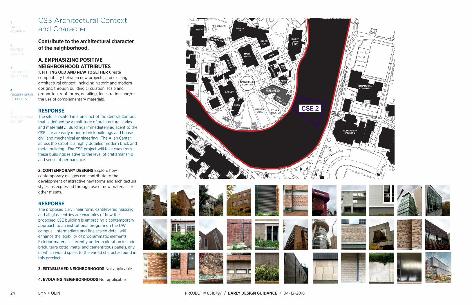
CS3 Architectural Context and Character
Contribute to the architectural character of the neighborhood.
A. EMPHASIZING POSITIVE NEIGHBORHOOD ATTRIBUTES1. FITTING OLD AND NEW TOGETHER Create compatibility between new projects, and existing architectural context, including historic and modern designs, through building circulation, scale and proportion, roof forms, detailing, fenestration, and/or the use of complementary materials.
RESPONSEThe site is located in a precinct of the Central Campus that is defined by a multitude of architectural styles and materiality. Buildings immediately adjacent to the CSE site are early modern brick buildings and house civil and mechanical engineering. The Allen Center across the street is a highly detailed modern brick and metal building. The CSE project will take cues from these buildings relative to the level of craftsmanship and sense of permanence.
2. CONTEMPORARY DESIGNS Explore how contemporary designs can contribute to the development of attractive new forms and architectural styles; as expressed through use of new materials or other means.
RESPONSEThe proposed curvilinear form, cantilevered massing and all glass entries are examples of how the proposed CSE building is embracing a contemporary approach to an institutional program on the UW campus. Intermediate and fine scaled detail will enhance the legibility of programmatic elements. Exterior materials currently under exploration include brick, terra cotta, metal and cementitious panels, any of which would speak to the varied character found in this precinct.
3. ESTABLISHED NEIGHBORHOODS Not applicable.
4. EVOLVING NEIGHBORHOODS Not applicable.
CSE 2
JOHNSO
N
ELECTRICAL ENGINEERING
AEROSPRSCH
PAUL GALLEN CTR
SIEG
MORE
ROBERTS
POWERPLANT
ENGLIB
LOEW
FACILITIESANNEXES
EN
G A
NN
EX
MUELLER
BAGLEY
GUG
GENHEIM
MARY GATES
RAINIERVISTA
MEANY
RED SQUARE
GERBERDING
SUZALLOLIB
DRUMHELLERFOUNTAIN
ALLENLIB
HUSKYUNION[HUB]
CHEM
EDMUNDSONPAVILION
INTRAMURALACTIVITIES
HALL HEALTH
THE UW CLUB
FLUKE
BLODEL
ANDERSON
BURKE
MASON RD N
E
WILCOX
TRAI
L
GILMAN
J
EFFE
RSO
N R
D
MO
NTL
AK
E B
OU
LEVA
RD
NE
SYLVAN THEATER
MOREANNEX
WINDTUNNEL
MECHENG
TRANSIT STATION
STEVENS WAY
4
312
6
FACILITYSERVICES
5
WILSON ANNEX
WILSONWINKEN-
WERDER
HEC ED BRIDGE
CSE 2

LMN + OLIN PROJECT # 6518797 / EARLY DESIGN GUIDANCE / 04-13–2016 25
1PROJECTOVERVIEW
5ARCHITECTURAL CONCEPT
3EXISTING SITE CONDITIONS
2CONTEXTANALYSIS
4PRIORITY DESIGN GUIDELINES
B. LOCAL HISTORY AND CULTURE1. PLACEMAKING Explore the history of the site and neighborhood as a potential placemaking opportunity. Look for historical and cultural significance, using neighborhood groups and archives as resources.
RESPONSEThe CSE project is centered within a context of engineering department buildings and university plant facilities. The new building is nestled in between More Hall, housing the Civil Engineering department, and the Mechanical Engineering building. It is located directly across Stevens Way from the Paul G. Allen Center, providing a direct link to the Computer Science and Engineering programs.

26 LMN + OLIN PROJECT # 6518797 / EARLY DESIGN GUIDANCE / 04–13–2016
1PROJECTOVERVIEW
5ARCHITECTURAL CONCEPT
3EXISTING SITE CONDITIONS
2CONTEXTANALYSIS
4PRIORITY DESIGN GUIDELINES
PL1 Connectivity
Complement and contribute to the network of open spaces around the site and the connections among them.
A. NETWORK OF OPEN SPACES1. ENHANCING OPEN SPACE Design the building and open spaces to positively contribute to a broader network of open spaces throughout the neighborhood.2. ADDING TO PUBLIC LIFE Seek opportunities to foster human interaction through an increase in the size and/or quality of project related open space available for public life.
RESPONSEThe University of Washington is in the process of finalizing a Campus Landscape Framework Plan. The plan establishes strategies for realizing a coherent campus through the development of multiple and stand-alone landscape projects. These projects are envisioned as part of a campus mosaic of open space that are developed according to guidelines for various open space types that serve a number of uses within the campus environment. These guidelines include criteria for campus greens, sports fields, and pathways. The site which comprises the proposed CSE project forms a major portion of the Lake Washington Connection, and any proposed development should help strengthen connectivity between Drumheller Fountain and Union Bay in Lake Washington.
A series of open spaces are proposed to be provided at regular intervals, spanning from Stevens Way to Mason Road. Moving from the top down, overflow outdoor café seating is proposed for Stevens Way, a gathering space is provided mid-way down the topography change on Snohomish Lane, the path opens up at building entries located on Jefferson Road, and path widens again at Mason Road where it intercepts pedestrian traffic flowing onto campus from the Hec-Edmundsen bridge that brings both bike and pedestrian traffic to campus over Montlake Boulevard.
B. WALKWAYS AND CONNECTIONS1. PEDESTRIAN INFRASTRUCTURE Connect on-site pedestrian walkways with existing public and private pedestrian infrastructure, thereby supporting pedestrian connections within and outside the project.2. PEDESTRIAN VOLUMES Provide ample space for pedestrian flow and circulation, particularly in areas where there is already heavy pedestrian traffic or where the project is expected to add or attract pedestrians to the area.3. PEDESTRIAN AMENITIES Opportunities for creating lively, pedestrian oriented open spaces to enliven the area and attract interest and interaction with the site and building should be considered.
RESPONSEInterviews with the campus landscape architect as well as on-site observation were conducted to understand pedestrian needs and relative volume of activity. The site is part of a larger corridor of campus circulation between two significant campus destinations, the Rainier Vista and the University of Washington’s athletic facilities. The site itself abuts Steven’s Way, which is a significant campus arterial for pedestrians and campus vehicles. The design establishes a plaza along Steven’s way with tables, chairs and fixed seating situated on pavement with canopy trees to provide over 50% shade in summer. The plaza will contain areas for parking up to fifty bicycles. For the campus pedestrian circulation corridor, a series of steps and a sloped section for walking bicycles is provided. Access to new building entries is compliant with ADA access guidelines.
C. OUTDOOR USES AND ACTIVITIES1. SELECTING ACTIVITY AREAS Concentrate activity areas in places with sunny exposure, views across spaces, and in direct line with pedestrian routes.2. INFORMAL COMMUNITY USES In addition to places for walking and sitting, consider including space for informal community use such as performances, farmer’s markets, kiosks and community bulletin boards, cafes or street vending.3. YEAR-ROUND ACTIVITY Where possible, include features in open spaces for activities beyond daylight hours and throughout the seasons of the year,
especially in neighborhood centers where active space will contribute vibrancy, economic health, and public safety.
RESPONSEOutdoor activity is localized at the plaza along Steven’s Way to capitalize on sun exposure. Open space is more generous between the CSE II building and the Mechanical Engineering Building as this is where sun exposure is at its maximum. Material and pattern continuity, alongside curving geometry of the terraced steps at the plaza strengthen the natural pedestrian circulation route between the Allen Center and CSE II and enhance pedestrian experience and activity. Benches, tables and chairs are strategically placed adjacent to building entries to encourage informal indoor to outdoor activity. A catenary lighting strategy enlivens the area while creating intimate and safe conditions for using the space at night. Quieter gathering spaces also take the form of a nested lawn and deck space situated further from the plaza area but nearer to the intended forested condition.

LMN + OLIN PROJECT # 6518797 / EARLY DESIGN GUIDANCE / 04-13–2016 27
1PROJECTOVERVIEW
5ARCHITECTURAL CONCEPT
3EXISTING SITE CONDITIONS
2CONTEXTANALYSIS
4PRIORITY DESIGN GUIDELINES
PL2 Walkability
Create a safe and comfortable walking environment that is easy to navigate and well-connected to existing pedestrian walkways and features.
A. ACCESSIBILITY1. ACCESS FOR ALL Provide access for people of all abilities in a manner that is fully integrated into the project design.2. ACCESS CHALLENGES Add features to assist pedestrians in navigating sloped sites, long blocks or other challenges.
RESPONSEEach of the building’s entrances are accessible, regardless of the level at which they occur along the topography of the site. Additionally, the building is designed to provide an internal accessible route from the topmost elevation at Steven’s Way, to the bottommost level at Mason Road. The design team is utilizing the University of Washington’s Access Guide as a reference in the design of both interior and exterior spaces, and the project has been reviewed by the UW Standing Committee on Accessibility.
B. SAFETY AND SECURITY1. EYES ON THE STREET Create a safe environment by providing lines of sight and encouraging natural surveillance through strategic placement of doors, windows, balconies and street-level uses.
RESPONSEThe length of the building is punctuated by well-lit building entries interspersed with windows all along the pedestrian ground level, opening up into what will be highly occupied administrative offices, undergraduate workrooms, and specialty labs. The landscape design will work to mitigate blind spots along the central paths of pedestrian site travel.
2. LIGHTING FOR SAFETY Provide lighting at sufficient lumen intensities and scales, including pathway illumination, pedestrian and entry lighting, and/or security lights.
RESPONSEPathway, pedestrian and entry lighting will be provided throughout the site for the safety of passersby and building occupants. Additionally, “Blue Light” emergency phone towers will be provided as part of this project, including at the Jefferson road level, which does not currently offer this amenity.
3. STREET-LEVEL TRANSPARENCY Ensure transparency of street-level uses (for uses such as nonresidential uses or residential lobbies), where appropriate, by keeping views open into spaces behind walls or plantings, at corners, or along narrow passageways. Choose semi-transparent rather than opaque screening.
RESPONSEA significant amount of transparent glazing is provided at the ground level portion of the building, throughout the entirety of the site. It is the intent of the project the multiple activity types are visible within the building to encourage a sense of community engagement from the inside out.
C. WEATHER PROTECTION1. LOCATIONS AND COVERAGE Overhead weather protection is encouraged and should be located at or near uses that generate pedestrian activity such as entries, retail uses, and transit stops. Address changes in topography as needed to provide continuous coverage the full length of the building, where possible.2. DESIGN INTEGRATION Integrate weather protection, gutters and downspouts into the design of the structure as a whole, and ensure that it also relates well to neighboring buildings in design, coverage, or other features.
RESPONSEOverhead weather protection will be provided at all building entries. Internal rainwater leaders will be provided to divert water from the rooftop to the campus storm sewer system.
D. WAYFINDING1. DESIGN AS WAYFINDING Use design features as a means of wayfinding wherever possible, and provide clear directional signage where needed.
RESPONSEMain entries will be clearly visible to passerby and will include signage identifying the corresponding floor level of entry. The building will be clearly marked with a building identification sign and address for visitors and emergency responders. Exterior wayfinding, including accessible routes, will be provided.

28 LMN + OLIN PROJECT # 6518797 / EARLY DESIGN GUIDANCE / 04–13–2016
1PROJECTOVERVIEW
5ARCHITECTURAL CONCEPT
3EXISTING SITE CONDITIONS
2CONTEXTANALYSIS
4PRIORITY DESIGN GUIDELINES
PL3 Street-Level Interaction
Encourage human interaction and activity at the street-level with clear connections to building entries and edges.
A. ENTRIES1. DESIGN OBJECTIVES Design primary entries to be obvious, identifiable, and distinctive with clear lines of sight and lobbies visually connected to the street. Scale and detail them to function well for their anticipated use and also to fit with the building of which they are a part, differentiating residential and commercial entries with design features and amenities specific to each.2. ENSEMBLE OF ELEMENTS Design the entry as a collection of coordinated elements including the door(s), overhead features, ground surface, landscaping, lighting, and other features.
RESPONSEAll building entries will be recognizable and provide full height glazing offering unobstructed views into the interior lobby spaces beyond. Landscape design, lighting and signage elements will complement architectural design to give sense of arrival and identity to the project.
B. RESIDENTIAL EDGESNot applicable.
C. RETAIL EDGESNot applicable.
PL4 Active Transportation
Incorporate design features that facilitate active forms of transportation such as walking, bicycling, and use of transit.
A. ENTRY LOCATIONS AND RELATIONSHIPS1. SERVING ALL MODES OF TRANSPORTATION Provide safe and convenient access points for all modes of travel.
RESPONSEBicycle racks are provided adjacent to all major entrances. All major building entrances are ADA accessible, and are close to existing Dial-A-Ride pick up locations on campus. Existing bus routes along Stevens Way will remain unchanged. Bus stops are not located directly at this site, but are adjacent to it.
2. CONNECTIONS TO ALL MODES Site the primary entry in a location that logically relates to building uses and clearly connects all major points of access.
RESPONSEThe primary building entry, leading into the main lobby and central vertical circulation for the building, is located off of Stevens Way. This street has the highest amount of pedestrian, vehicle, bus, and bike traffic. This primary location also gathers Computer Science and Engineering pedestrian traffic coming across the street from the Allen Center and is the culminating point of arrival in Central Campus for pedestrians moving up Snohomish Lane.
B. PLANNING AHEAD FOR BICYCLISTS1. EARLY PLANNING Consider existing and future bicycle traffic to and through the site early in the process so that access and connections are integrated into the project along with other modes of travel.
RESPONSEBikes will access the site from two primary locations: Stevens Way and Burke Gilman trail. Significant existing bike traffic along Stevens Way suggests this elevation of the project include a clearly visible
and accessible bike entry and connection to the site. Bicyclists arriving at the site via the Burke Gilman trail, or from further afield across Montlake, using the Hec Ed bridge, will have two options for approaching the building: Mason and Jefferson Roads. Bike storage areas will be provided at each of these locations.
2. BIKE FACILITIES Facilities such as bike racks and storage, bike share stations, shower facilities and lockers for bicyclists should be located to maximize convenience, security, and safety.
RESPONSEProposed design features include a secure bike storage room, exterior bike racks and shower facilities near building entrances to promote bike use for building occupants. Bicycle parking will be provided per the UW Facilities Services Design Guide requirements, where covered exterior bike parking is required for 10% of the building population, and secured parking is required for 3% of the building population. In addition, all existing racks will be replaced as part of this project.
3. BIKE CONNECTIONS Facilitate connections to bicycle trails and infrastructure around and beyond the project. Design bicycling access points so that they relate to the street grid and include information about connections to existing trails and infrastructure where possible.
RESPONSEAll bicycle facilities included in this project will be designed to complement the existing extensive bicycle trail and support system on the UW campus.
C. PLANNING AHEAD FOR TRANSIT3. TRANSIT CONNECTIONS Where no transit stops are on or adjacent to the site, identify where the nearest transit stops and pedestrian routes are and include design features and connections within the project design as appropriate.
RESPONSEProposed site is a short distance from Metro bus stops along Stevens Way, and less than 0.3 miles from the University Sound Transit station.

LMN + OLIN PROJECT # 6518797 / EARLY DESIGN GUIDANCE / 04-13–2016 29
1PROJECTOVERVIEW
5ARCHITECTURAL CONCEPT
3EXISTING SITE CONDITIONS
2CONTEXTANALYSIS
4PRIORITY DESIGN GUIDELINES
DC1 Project Uses and Activities
Optimize the arrangement of uses and activities on site.
A. ARRANGEMENT OF INTERIOR SPACES1. VISIBILITY Locate uses and services frequently used by the public in visible or prominent areas, such as at entries or along the street front.
RESPONSEMain public entry into central lobby and grand circulation stair is located on Stevens Way. Café on the first floor faces Stevens Way to the west and will be accessible to public. Large classrooms and lecture hall are located off Jefferson.
2. GATHERING PLACES Maximize the use of any interior or exterior gathering spaces.
RESPONSEProposed building incorporates Café on the first floor and Events Space on the rooftop for gathering spaces that can cater to both informal and formal occasions.
3. FLEXIBILITY Build in flexibility so the building can adapt over time to evolving needs, such as the ability to change residential space to commercial space as needed.
RESPONSEExterior design and structural system of the building are based on 10’ planning module and are intended to accommodate future interior renovations without major overhaul to the building systems.
4. VIEWS AND CONNECTIONS Locate interior uses and activities to take advantage of views and physical connections to exterior spaces and uses, particularly activities along sidewalks, parks or other public spaces.
RESPONSEExterior terrace areas with private and public access
will be provided at eastern edges of the building, providing the users with great views to the Lake Washington and the Cascades. Café on the first floor will face Stevens Way to the west and provide interaction space for building occupants, students and the public.
B. VEHICULAR ACCESS AND CIRCULATION1. ACCESS LOCATION AND DESIGN Choose locations for vehicular access, service uses, and delivery areas that minimize conflict between vehicles and non-motorists wherever possible. Emphasize use of the sidewalk for pedestrians, and create safe and attractive conditions for pedestrians, bicyclists, and drivers.
RESPONSEService areas are located away from pedestrian circulation and building entrances.
2. FACILITIES FOR ALTERNATIVE TRANSPORTATION Locate any facilities for alternative transportation such as shared vehicles, carpooling and charging stations for electric vehicles in prominent locations that are convenient and readily accessible to expected users.
RESPONSEProposed design does not include provisions for alternate transportation at this time, since the project does not affect existing parking capacity on site.
C. PARKING AND SERVICE USES1. BELOW-GRADE PARKING Not applicable. Parking is not provided.
2. VISUAL IMPACTS Not applicable.
3. MULTIPLE USES Not applicable.
4. SERVICE USES Locate and design service entries, loading docks, and trash receptacles away from pedestrian areas or to a less visible portion of the site to reduce possible impacts of these facilities on building aesthetics and pedestrian circulation.
RESPONSEProposed loading zone is located away from major pedestrian circulation on site and building entrances to minimize conflict with students and building users. The loading area is placed adjacent to an existing service/testing yard for the Civil Engineering Building. Existing Snohomish Way will be replaced by new site design to increase ADA accessibility and add attractive features for pedestrians.

30 LMN + OLIN PROJECT # 6518797 / EARLY DESIGN GUIDANCE / 04–13–2016
1PROJECTOVERVIEW
5ARCHITECTURAL CONCEPT
3EXISTING SITE CONDITIONS
2CONTEXTANALYSIS
4PRIORITY DESIGN GUIDELINES
DC2 Architectural Concept
Develop an architectural concept that will result in a unified and functional design that fits well on the site and within its surroundings.
A. MASSING1. SITE CHARACTERISTICS AND USES Arrange the mass of the building taking into consideration the characteristics of the site and the proposed uses of the building and its open space. In addition, special situations such as very large sites, unusually shaped sites, or sites with varied topography may require particular attention to where and how building massing is arranged as they can accentuate mass and height.
RESPONSEThe site is bordered by Stevens Way and Mason Road to the west and east, and by the Mechanical Engineering Building and More Hall to the north and south. The building spans over Jefferson Road. Other site considerations include maintaining Snohomish Lane along the north edge of the building, the More Hall civil engineering testing yard at the southeast corner of the site, and the existing fuel oil tank on the north side of the site on Jefferson Road. Balancing these existing physical elements with pedestrian movement and maintaining appropriate area for the main entries to More Hall and Mechanical Engineering result in an elongated building shape that also accommodates the proposed program. The ends of the building are eased and rounded to accentuate the open spaces at the east and west ends.
2. REDUCING PERCEIVED MASS Use secondary architectural elements to reduce the perceived mass of larger projects. Consider creating recesses or indentations in the building envelope; adding balconies, bay windows, porches, canopies or other elements; and/or highlighting building entries.
RESPONSEAs noted above, the east and west ends of the building are eased and rounded to accentuate open
space at the ends where pedestrians initially engage the building. This approach has the added benefit of diminishing the overall length of the building since the curvature takes it out of the sightline.
B. ARCHITECTURAL AND FAÇADE COMPOSITION1. FAÇADE COMPOSITION Design all building facades – including alleys and visible roofs – considering the composition and architectural expression of the building as a whole. 2. BLANK WALLS Avoid large blank walls along visible facades wherever possible.
RESPONSEMateriality and articulation of façade elements are proposed to modulate across the face of the entire building in order to visually break down the overall scale and length of the building. All façades of the building are visible from public ways and will therefore be given equal attention.
C. SECONDARY ARCHITECTURAL FEATURES1. VISUAL DEPTH AND INTEREST Add depth to facades where appropriate by incorporating balconies, canopies, awnings, decks, or other secondary elements into the façade design.
RESPONSESouth and east facing windows will have solar shading elements to reduce heat gain.
2. DUAL PURPOSE ELEMENTS Consider architectural features that can be dual purpose – adding depth, texture, and scale as well as serving other project functions.
RESPONSEThe proposed building massing features a cantilevered slab for individual offices, which doubles as an overhang for major entrances and creates medium-scaled granularity to the exterior design.
3. FIT WITH NEIGHBORING BUILDINGS Use design elements to achieve a successful fit between a building and its neighbors.
RESPONSEExterior building design will feature complementary and contextual elements to be a good neighbor to adjacent engineering and other existing campus buildings.
D. SCALE AND TEXTURE1. HUMAN SCALE Incorporate architectural features, elements, and details that are of human scale into the building facades, entries, retaining walls, courtyards, and exterior spaces in a manner that is consistent with the overall architectural concept. Pay special attention to the first three floors of the building in order to maximize opportunities to engage the pedestrian and enable an active and vibrant street front.
RESPONSEFaçade design will incorporate architectural elements of varying scales to create attractive and contextual response to the heavily pedestrian nature of the site. Site design will incorporate design elements to promote outdoor seating areas near Café to promote interaction and sense of vibrant public space.
2. TEXTURE Design the character of the building, as expressed in the form, scale, and materials, to strive for a fine-grained scale, or “texture,” particularly at the street level and other areas where pedestrians predominate.
RESPONSEThe building will be designed to read at multiple scales with a richness that becomes more legible as one approaches the building. Fine grain texture on solid surfaces of the façade will be critical in achieving this effect.
E. FORM AND FUNCTION1. LEGIBILITY AND FLEXIBILITY Strive for a balance between building legibility and flexibility. Design buildings such that their primary functions and uses can be readily determined from the exterior, making the building easy to access and understand. At the same time, design flexibility into the building so that is may remain useful over time even as specific programming needs evolve.
RESPONSEUse of glass curtainwall systems along major entrances is intended to increase legibility of activities inside the building and promote an inviting atmosphere to the students and public. The building plan is based on a consistent planning module so that owner can repurpose sections of the building without significant structural modifications in the future.

LMN + OLIN PROJECT # 6518797 / EARLY DESIGN GUIDANCE / 04-13–2016 31
1PROJECTOVERVIEW
5ARCHITECTURAL CONCEPT
3EXISTING SITE CONDITIONS
2CONTEXTANALYSIS
4PRIORITY DESIGN GUIDELINES
DC3 Open Space Concept
Integrate open space design with the design of the building so that each complements the other.
A. BUILDING-OPEN SPACE RELATIONSHIP1. INTERIOR/EXTERIOR FIT Develop an open space concept in conjunction with the architectural concept to ensure that interior and exterior spaces relate well to each other and support the functions of the development.
B. OPEN SPACE USES AND ACTIVITIES1. MEETING USER NEEDS Plan the size, uses, activities, and features of each open space to meet the needs of expected users, ensuring each space has a purpose and function.2. MATCHING USES TO CONDITIONS Respond to changing environmental conditions such as seasonal and daily light and weather shifts through open space design and/or programming of open space activities.3. CONNECTIONS TO OTHER OPEN SPACES Site and design project-related open spaces should connect with, or enhance, the uses and activities of other nearby public open space where appropriate. Look for opportunities to support uses and activities on adjacent properties and/or the sidewalk.
RESPONSEThe open space design is intended to provide significant open space to occupants of the new building. The exterior areas include a large plaza for seating or informal events and a small sitting green located underneath a canopy comprised of coastal forest and ornamental adapted species. The inclusion of deciduous canopy trees capable of shading the majority of occupied areas in summer and shedding leaves in cool months attenuates the microclimate of the site. Generous seating is provided adjacent to major areas of circulation and along the building perimeter.
4. MULTIFAMILY OPEN SPACE Not applicable.
C. DESIGN1. REINFORCE EXISTING OPEN SPACE Where a strong open space concept exists in the neighborhood, reinforce existing character and patterns of street planting, buffers or treatment of topographic changes. Where no strong patterns exist, initiate a strong open space concept, where appropriate, that other projects can build upon in the future.2. AMENITIES AND FEATURES Create attractive outdoor spaces well-suited to the uses envisioned for the project. Use a combination of hardscape and plantings to shape these spaces and to screen less attractive areas as needed. Use a variety of features, such as planters, green roofs and decks, groves of trees, and vertical green trellises along with more traditional foundation plantings, street trees, and seasonal displays.3. SUPPORT NATURAL AREAS Create an open space design that retains and enhances on-site natural areas and connects to natural areas that may exist off-site and may provide habitat for wildlife.
RESPONSEThe site design encourages the development of a forest canopy habitat that is supportive of many species found in the Coastal Plain Forest of Washington state. As the plantings mature it is anticipated that raptors, songbirds and ground thrushes will find beneficial habitat. The site’s current condition is significantly developed with a predominance of non-native ornamentals. New plantings will consist of a palette of native and natively adaptive species greater than 50%.

32 LMN + OLIN PROJECT # 6518797 / EARLY DESIGN GUIDANCE / 04–13–2016
1PROJECTOVERVIEW
5ARCHITECTURAL CONCEPT
3EXISTING SITE CONDITIONS
2CONTEXTANALYSIS
4PRIORITY DESIGN GUIDELINES
DC4 Exterior Elements and Finishes
Use appropriate and high quality elements and finishes for the building and its open spaces.
A. BUILDING MATERIALS1. EXTERIOR FINISH MATERIALS Building exteriors should be constructed of durable and maintainable materials that are attractive even when viewed up close. Materials that have texture, or lend themselves to a high quality of detailing are encouraged.
RESPONSEExterior cladding will consist of glass, metal panel and masonry. The choice of quality exterior materials will emphasize University’s long term vision in promoting a campus environment suitable for higher education and academic excellence.
2. CLIMATE APPROPRIATENESS Select durable and attractive materials that will age well in Seattle’s climate, taking special care to detail corners, edges, and transitions. Highly visible features, such as balconies, grilles and railings should be especially attractive, well-crafted and easy to maintain. Pay particular attention to environments that create harsh conditions that may require special materials and details, such as marine areas or open or exposed sites.
RESPONSEThe project will propose materials that are durable, maintainable and appropriate to a campus environment. A high level of craftsmanship is intended to be realized for the exterior.
B. SIGNAGE1. SCALE AND CHARACTER Add interest to the streetscape with exterior signs and attachments that are appropriate in scale and character to the project and its environs. Signage should be compatible in character, scale, and locations while still allowing businesses to present a unique identity.
RESPONSEA complete signage package will be provided as part of this project and will include environmental graphics illustrating clear wayfinding and building identity. Building identity signage for pedestrians, vehicles and emergency responders will be highly visible and clear to passerby.
2. COORDINATION WITH PROJECT DESIGN Develop a signage plan within the context of architectural and open space concepts, and coordinate the details with façade design, lighting, and other project features to complement the project as a whole, in addition to the surrounding context.
RESPONSESignage will be fully integrated with the architecture, landscape and lighting design for the project.
C. LIGHTING1. FUNCTIONS Use lighting both to increase site safety in all locations used by pedestrians and to highlight architectural or landscape details and features such as entries, signs, canopies, plantings and art.
RESPONSEA complete lighting design will be provided that is integrated with the architecture, landscape and signage designs. Proposed pedestrian paths on site will be illuminated to promote a sense of safety. Site design features and building entries will be highlighted to augment wayfinding while providing an attractive atmosphere for pedestrian movement.
2. AVOIDING GLARE Design project lighting based upon the uses on and off site, taking care to provide illumination to serve building needs while avoiding off-site night glare and light pollution.
RESPONSEExterior lighting will be designed to protect the night sky. Lighting will be focused on building entries and pathway lighting.
D. TREES, LANDSCAPE AND HARDSCAPE MATERIALS1. CHOICE OF PLANT MATERIALS Reinforce the overall architectural and open space design concepts through the selection of landscape materials.
RESPONSESelected plant materials will be supportive of the existing campus layered ecology of deciduous and conifer trees and will be expressive of Pacific Northwest vegetation.
2. HARDSCAPE MATERIALS Use exterior courtyards, plazas, and other hard surfaced areas as an opportunity to add color, texture, and/or pattern and enliven public areas through the use of distinctive and durable paving materials. Use permeable materials wherever possible.3. LONG RANGE PLANNING Select plants that upon maturity will be of appropriate size, scale, and shape to contribute to the site as intended. 4. PLACE MAKING Create a landscape design that helps define spaces with significant elements such as trees.
RESPONSEUnified paving will be used to distinguish the plaza space at Steven’s Way. Boulders and rock walls are selectively employed to establish more informal spaces where the character of the site transitions from campus to forest. Vegetation is the primary thread in stitching the pedestrian fabric together. An allee of trees adorns Stevens Way, contributing to an ordered and cathedral-like space between the Allen Center and CSE II. Trees are planted more informally and in groves to negotiate steep slopes and to screen the powerplant and parking lot downslope. While many trees are scheduled for removal as a result of interference in the construction area zone, it is desired to save the two large existing Pin Oaks between the Mechanical Engineering Building and CSE II. Large canopy oak trees are selectively chosen to divide the surface of the proposed plaza; while not native to the region, the large canopy trees with a soft understory will keep the plaza from becoming excessively monolithic and abstract.
E. PROJECT ASSEMBLY AND LIFESPAN1. DECONSTRUCTION When possible, design the project so that it may be deconstructed at the end of its useful lifetime, with connections and assembly techniques that will allow reuse of materials.
RESPONSEUse of metal studs for exterior wall and structural steel for framing will allow for recycling at the end of project lifetime, minimizing landfill volume from masonry.

LMN + OLIN PROJECT # 6518797 / EARLY DESIGN GUIDANCE / 04-13–2016 33
1PROJECTOVERVIEW
5ARCHITECTURAL CONCEPT
3EXISTING SITE CONDITIONS
2CONTEXTANALYSIS
4PRIORITY DESIGN GUIDELINES
5 Architectural Concept

34 LMN + OLIN PROJECT # 6518797 / EARLY DESIGN GUIDANCE / 04–13–2016
1PROJECTOVERVIEW
5ARCHITECTURAL CONCEPT
3EXISTING SITE CONDITIONS
2CONTEXTANALYSIS
4PRIORITY DESIGN GUIDELINES

801 Second Avenue, Suite 501Seattle, WA 98104T 206.682.3460www.lmnarchitects.com
150 S Independence Mall WPhiladelphia, PA 19106T 215.440.0030www.theolinstudio.com