university of peloponnese adaptive optical technologies for optical transmission systems maki nanou,...
TRANSCRIPT

University of Peloponnese
Adaptive Optical Technologies for Optical Transmission Systems
Maki Nanou, George-Othon Glentis,
Kristina Georgoulakis, Chris Matrakidis,
Christina (Tanya) Politi, Alexandros Stavdas

Outline
Basic Concepts of Optical Communications Fiber Impairments & Compensation Techniques Optical Transmission Simulations Results Conclusion
University of PeloponneseDept. of Inform. & Telecommunications

Traffic Growth
University of Peloponnese
Until 2000: Voice Traffic dominates
After 2004: Data Traffic dominates 60% / year
Traffic growth of 60% per year outstrips the growth in capacity of commercial systems.
While the entire traffic in North American core Network could be carried on a single fiber until 2008, in 2011 more than two fibers were required. Every 3 years the required number of fibers will double.
Increased capacity ↔ Advanced Modulation Formats
20% / year
(*) Cisco Forecast

Non Return To Zero – On – Off Keying
University of PeloponneseDept. of Inform. & Telecommunications
Output Intensity
Vπ swing
t
quaternary point bias
MZMLASERopticalsignal
Most commonly used (widely deployed)
OOK: switching ON and OFF the amplitude of an optical carrier signal (Intensity Modulation Only)
External Modulation: biased at the quadrature point of the MZM transfer function, and driven by an electrical binary NRZ-ASK signal with peak-to-peak amplitude of Vπ.
Input Voltage
Simple Tx/Rx Configurations
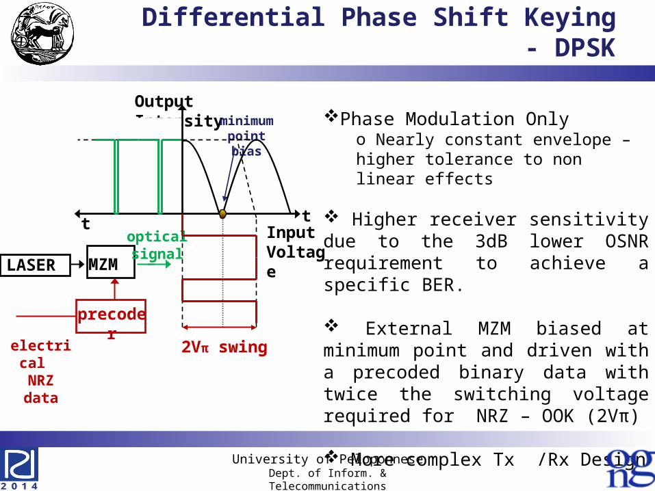
Differential Phase Shift Keying - DPSK
Input Voltage
Output Intensity
2Vπ swing
t
minimumpoint bias
MZMLASER
opticalsignal
electrical NRZ data
precoder
t
Phase Modulation Onlyo Nearly constant envelope – higher tolerance to non linear effects
Higher receiver sensitivity due to the 3dB lower OSNR requirement to achieve a specific BER.
External MZM biased at minimum point and driven with a precoded binary data with twice the switching voltage required for NRZ – OOK (2Vπ)
More complex Tx /Rx Design
University of PeloponneseDept. of Inform. & Telecommunications

Fiber Impairments in Single Channel Systems
Tx
SMF
G Rx
DCF
G
Linear
Losses Dispersion
Non Linear
SPM
compensates SMF losses
compensates dispersion
compensates DCF losses
inserts ASE noise
University of PeloponneseDept. of Inform. & Telecommunications
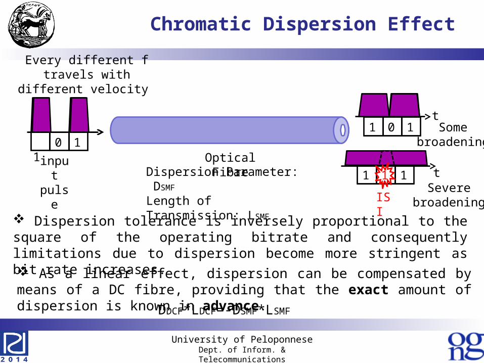
Chromatic Dispersion Effect
Optical Fibre
t1 1 0
1 1 1 t
ISI
Some broadening
Severebroadening
input pulse
Every different f travels with different velocity
1 1 0
Dispersion Parameter: DSMF
Length of Transmission: LSMF
As a linear effect, dispersion can be compensated by means of a DC fibre, providing that the exact amount of dispersion is known in advance.
DDCF*LDCF=-DSMF*LSMF
Dispersion tolerance is inversely proportional to the square of the operating bitrate and consequently limitations due to dispersion become more stringent as bit rate increases.
University of PeloponneseDept. of Inform. & Telecommunications

Electronic Equalization
EE are applied after the receivero no need in intervening in the already installed fibre links
Can cope with variable amounts of dispersion
EE attempts to reverse the distortion incurred by a signal transmitted through a channel. It can be a simple linear filter or a complex algorithm.
Receiver (Rx)
Electric Filter
ClockRecovery
PIN
y(t) y(n) I(n)
Electronic Equalizer
ADC
University of PeloponneseDept. of Inform. & Telecommunications
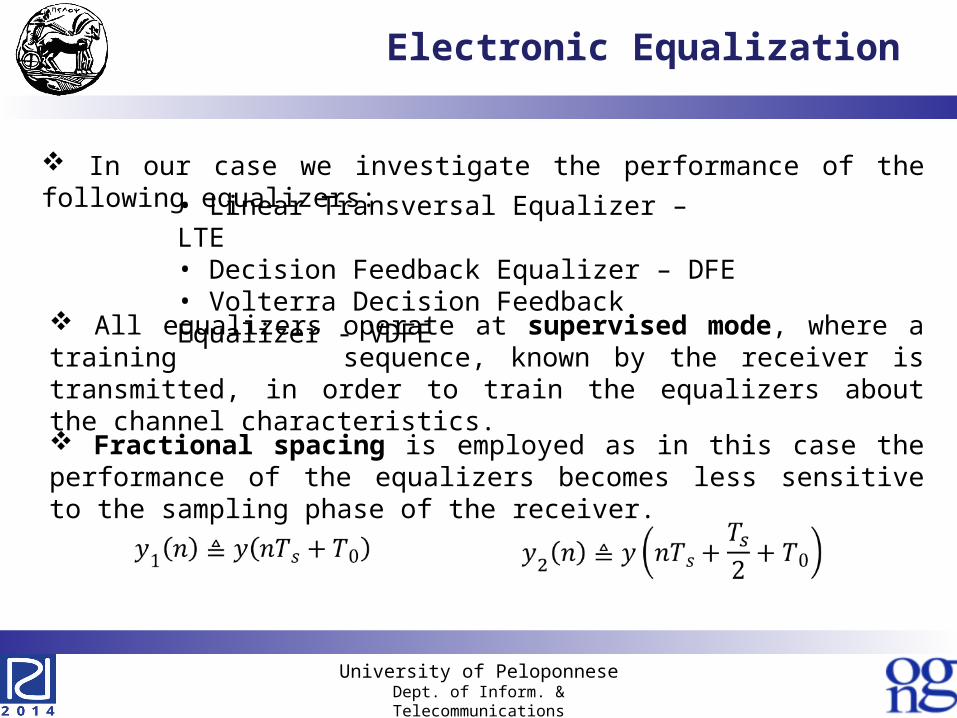
Electronic Equalization
All equalizers operate at supervised mode, where a training sequence, known by the receiver is transmitted, in order to train the equalizers about the channel characteristics.
Fractional spacing is employed as in this case the performance of the equalizers becomes less sensitive to the sampling phase of the receiver.
In our case we investigate the performance of the following equalizers:
• Linear Transversal Equalizer – LTE• Decision Feedback Equalizer – DFE• Volterra Decision Feedback Equalizer - VDFE
University of PeloponneseDept. of Inform. & Telecommunications

Linear Transversal equalizer - LTE
LTE is the simplest form of electronic equalizers. The incoming signal is processed by a linear filter.
In order to retrieve the transmitted sequence, FS-LTE operates according to:
University of PeloponneseDept. of Inform. & Telecommunications

Decision Feedback equalizer - DFE
DFE consists of two parts: a Feed forward part that is driven by the received waveform and a Feedback part that is driven by the estimations of the previous symbols.
FS-DFE operates according to:
The performance of linear equalizers is constrained when applied to non linear systems.

Non Linear Photodetector
Photodiode operates on a square law principle, in which the output of the detector is proportional to the intensity (i.e., the square of the input signal magnitude).
The main reason of non linearity in optical systems is induced by the detector during the conversion of optical to electrical.
Although it is a simple circuit, it is nonlinear and as such it is difficult to correct linear distortions such as CD.
University of PeloponneseDept. of Inform. & Telecommunications
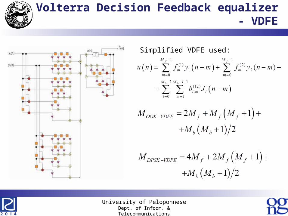
Volterra Decision Feedback equalizer - VDFE
Simplified VDFE used:
University of PeloponneseDept. of Inform. & Telecommunications

Complexity Calculations
University of PeloponneseDept. of Inform. & Telecommunications

Simulation Setup
10 spans x 100km (1000km)
3 spans x 100km (300km)
10 Gb/s bitrate10 Gb/s bitrate
40 Gb/s bitrate40 Gb/s bitrate
G
Transmission Span (x N)
Tx Rx
BER Estimationw/o EDC
equalizer
BER Estimationwith EDC
SMF DCF
G
University of PeloponneseDept. of Inform. & Telecommunications
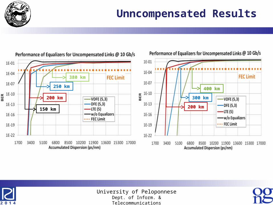
Unncompensated Results
150 km
200 km
250 km
380 km
200 km
300 km
400 km
University of PeloponneseDept. of Inform. & Telecommunications

NRZ-OOK Results (1)
87.5 %
85 %
80 %
70% 94%
98%
University of PeloponneseDept. of Inform. & Telecommunications

NRZ-DPSK Results (1)
OCR=70%-90% 10Gb/s & 40Gb/s DPSK
University of PeloponneseDept. of Inform. & Telecommunications

NRZ-OOK Dispersion ToleranceReduces
Upgrading Scenario Setup
G
Total Length of 1000 km (10 spans x 100 km)
Tx
SMF DCF
G
Operating at 10 Gb/sOperating at 40 Gb/s
99 % OCR
BER Estimationw/o EDC
BER Estimationwith EDC
equalizer
NRZ-DPSK
NRZ-OOK
NRZ-DPSK
Rx
University of PeloponneseDept. of Inform. & Telecommunications

Upgrading Scenarios Results
Upgrading a system 10-40 NRZ & DPSK
University of PeloponneseDept. of Inform. & Telecommunications
Conclusion
Low cost, adaptive techniques of optical transmission, consisting of optical and electronic equalization, were studied by simulating configurations with realistic link parameters.
Here, the interplay between optical and electronic techniques for physical impairment mitigation for DD optical transmission with various performance/complexity tradeoffs, is presented.
It has become evident that even in the absence of FEC, low complexity equalizers can perform sufficiently well in conjunction with optical compensation.
Low complexity Volterra equalizers can be used to support the migration of a system from 10 to 40 Gb/s.
University of PeloponneseDept. of Inform. & Telecommunications

Q&A
Thank you for your attention!
This research was funded by the Operational Program "Education and Lifelong Learning" of the Greek National Strategic Reference Framework (NSRF) Research Funding Program: THALES PROTOMI, grant number MIS 377322.
University of PeloponneseDept. of Inform. & Telecommunications