university of houston master construction … 63... · astm c94 specification for ready mixed...
TRANSCRIPT

University of Houston Master Construction Specifications Insert Project Name
AE Project Number: Drilled Concrete Piers 31 63 29 – 1 Revision Date: 1/29/2014
SECTION 31 63 29 – DRILLED CONCRETE PIERS (CAISSONS)
PART 1 - GENERAL
1.1 RELATED DOCUMENTS
A. Drawings and general provisions of Contract, including General and Supplementary Conditions and Division-1 Specification sections, apply to work of this section.
B. Information concerning a sub-surface soil investigation by the Owner’s Geotechnical Engineer is available and will be furnished by the Owner upon request. The contractor may use the data included therein for his general information only. The Architect/Engineer is not responsible for the accuracy or applicability of the data therein.
1.2 DEFINITIONS
A. Casing: Steel cylinder used to resist earth and water pressures, to serve as concrete form, and to protect personnel.
B. Dry Method: A method of pier installation in which concrete is placed in the dry. Casing may or may not be used to maintain sidewall stability.
C. Owner’s Representative: The Architect, Structural Engineer, or Geotechnical Engineer authorized to act on behalf of the Owner.
D. Owner’s Representative - Geotechnical Engineer: The Geotechnical Engineer specifically authorized to carry out the responsibilities defined in this specification.
E. Probe hole: A 1.6 to 2.5 inch diameter hole usually drilled by air percussion methods to a required depth below the pier bottom. The Geotechnical Engineer feels the probe hole by lowering and raising a hooked rod. The size and amount of seams found enables the determination of the soundness of the subsurface formation.
F. Slurry Displacement Method: Method of drilling and concreting in which controlled slurry consisting of water, with or without additives such as bentonite, attapulgite, or polymer, is used to stabilize the hole. The slurry may be used either to maintain the stability of the uncased drilled pier hole or to allow concrete placement when water seepage into a drilled pier hole is too severe to permit concreting in the dry or both.
G. Tremie method: Procedure for placing concrete under water or slurry using a watertight steel pipe or tube to place concrete without washing out cement fines.
1.3 STANDARDS
A. The following Standards are listed in this specification:
ASTM A36 Standard Specification for Carbon Structural Steel ASTM A283 Standard Specification for Low and Intermediate Tensile
Strength Carbon Steel Plates ASTM A929 Standard Specification for Steel Sheet, Metallic-Coated
by the Hot-Dip Process for Corrugated Steel Pipe ASTM C33 Standard Specification for Concrete Aggregates ASTM C94 Specification for Ready Mixed Concrete ASTM C150 Specification for Portland Cement
University of Houston Master Construction Specifications Insert Project Name
AE Project Number: Drilled Concrete Piers 31 63 29 – 2 Revision Date: 1/29/2014
ASTM D1143 Standard Test Method for Piles Under Static Axial Compressive Load
ASTM D4380 Standard Test Method for Density of Bentonitic Slurries ASTM D4381 Standard Test Method for Sand Content by Volume of
Bentonitic Slurries ASTM D4972 Standard Test Method for pH of Soils
1.4 SCOPE OF WORK
A. The Drilling Contractor shall furnish all labor, materials, services, equipment (including temporary casings and/or dewatering where required), and shall install all piers at the locations and depths shown on the drawings or as otherwise directed by the Owner's Geotechnical Engineer. Installation methods compatible with the design may be used if acceptable to the Owner’s Geotechnical Engineer. Methods that are not compatible with the design shall be excluded from consideration.
B. The Drilling Contractor shall furnish and place all reinforcing steel, dowels, and anchor bolts that are shown on the drawings to be embedded in the pier.
C. The Drilling Contractor shall furnish all materials and labor as required to perform the load tests as specified herein and on the drawings.
D. The General Contractor shall provide all necessary excavation, sheeting and bracing or other adequate maintenance of excavation banks, suitable runways and ramps as necessary for access of pier drilling, control of ground and surface water as necessary to keep the work area sufficiently dry, suitable access roads for movement of equipment and materials to and from pier locations, field layout required for pier work including setting and maintaining a location stake for each pier and giving cut-off grades on all piers, removal and replacement of all overhead and underground obstructions as required, and coordination of all concrete ordering and delivery.
1.5 QUALIFICATIONS
A. Drilled piers shall be installed by a specialty Drilling Contractor with suitable equipment, competent personnel, and a reputation of satisfactorily performing the work. The Contractor shall have a minimum of 5 years successful experience and a minimum of 5 successful installations on projects of a similar size and scope to this project and of using similar installation methods as may be anticipated for this project. Evidence of compliance with this section shall be submitted to the Architect/Engineer prior to entering into a contract for the work.
1.6 QUALITY ASSURANCE
The Contractor is responsible for quality control, including workmanship and materials furnished by his subcontractors and suppliers.
A. Codes and Standards: The Drilling Contractor shall comply with the provisions of the following codes, specifications, and standards, except where more stringent requirements are shown or specified:
1. ACI 301 - "Specifications for Structural Concrete for Buildings".
2. ACI 117 - “Specifications for Tolerances for Concrete Construction and Materials."

University of Houston Master Construction Specifications Insert Project Name
AE Project Number: Drilled Concrete Piers 31 63 29 – 3 Revision Date: 1/29/2014
3. ACI 318 - "Building Code Requirements for Reinforced Concrete".
4. Concrete Reinforcing Steel Institute (CRSI), "Manual of Standard Practice".
5. ANSI/AWS D1.1 "Structural Welding Code - Steel".
6. ANSI/AWS D1.4 "Structural Welding Code – Reinforcing Steel".
In addition, all applicable building code and local regulations shall be followed. In case of conflict, the strictest interpretation shall govern.
B. Survey Work:
1. The General Contractor shall employ a qualified and licensed professional engineer/land surveyor to perform all surveys, layouts and measurements for drilled pier work including the layout of anchor rods and/or reinforcing steel dowels embedded in drilled piers. The surveyor shall conduct the layout work for each drilled pier to the lines and levels required prior to beginning excavation and shall make actual in-place measurements of each drilled pier plan location, shaft diameter, bottom and top elevations and deviations from specified tolerances.
2. The surveyor shall record and submit all information pertinent to each drilled pier and cooperate with other testing and inspection personnel to provide data for all required reports.
C. Testing Laboratory Requirements: The Drilling Contractor shall cooperate with all testing and inspection personnel employed to perform field quality control tests and inspections. See Testing Laboratory section of the specifications for required tests and inspections to be performed by the Testing Laboratory and Geotechnical Engineer.
Inspection or testing by the Owner does not relieve the Contractor of his responsibility to perform the Work in accordance with the Contract Documents.
1.7 JOB CONDITIONS
A. Site Information:
1. Data on indicated subsurface conditions are not intended as representations or warranties of continuity of such conditions. It is expressly understood that Owner will not be responsible for interpretations or conclusions drawn therefrom by the Contractor. The data are made available for convenience of the Contractor.
2. The Contractor may make additional test borings and other exploratory operations at no additional cost to the Owner.
3. The Contractor shall inspect the site prior to drilling operations and shall determine any constraints to the work presented by the existing surface conditions and report them to the Owner’s Representative.
B. Protection of Existing Structures: Locate all existing underground structures and utilities that are to remain in service during construction. Protect above-ground structures, underground utilities and other construction from damage caused by drilling operations. Report any conflicts between drilling work and underground utilities and structures to the Owner’s Representative and do not proceed with the work until the conflict is resolved.

University of Houston Master Construction Specifications Insert Project Name
AE Project Number: Drilled Concrete Piers 31 63 29 – 4 Revision Date: 1/29/2014
C. Survey of Existing Structures: Record and report to Architect/Engineer surveyed elevation benchmarks on structures where directed by the Owner’s Representative before commencing work, when structures are adjacent to drilling operations. Record and report elevation of each benchmark at least twice a day while drilling is in progress. Should benchmark readings indicate displacement, halt drilling operations until corrective action has been provided and is acceptable to the Owner’s Representative and the Owner.
1.8 PREINSTALLATION CONFERENCE
A. At least 7 days prior to beginning pier installation, the Contractor shall conduct a meeting to review the proposed excavation, inspection, and concrete and reinforcement placement methods and procedures to produce pier construction of the required quality. Also review requirements for submittals, status of coordinating work and availability of materials. Establish work progress schedule and procedures for bearing surface inspection, materials testing, and certifications. The Contractor shall send a pre-installation conference agenda to all attendees 7 days prior to the scheduled date of the conference.
B. The Contractor shall require responsible representatives of every party who is concerned with the concrete work to attend the conference, including but not limited to the following:
Contractor's Superintendent Laboratory responsible for field material testing Drilling Subcontractor Ready-Mix Concrete Producer Geotechnical Engineer Owner's and Architect's/Engineer's Representative
C. Minutes of the meeting shall be recorded, typed and printed by the Contractor and distributed by him to all parties concerned within 5 days of the meeting. One copy of the minutes shall be transmitted to the following for information purposes:
Owner's Representative Architect Engineer-of-Record
D. The Engineer shall be present at the conference. The Contractor shall notify the Engineer at least 7 days prior to the scheduled date of the conference.
1.9 SUBMITTALS
A. Concrete Mix Design: Submit concrete mix designs suitable for method of concrete placement for Engineer and Owner's Testing Laboratory approval prior to pier installation.
B. Drilling Records: The Contractor and the Owner's Geotechnical Engineer or other authorized inspector shall each submit copies of the drilling record for each pier to the Architect/Engineer immediately after drilling. The reports shall indicate the name of the job, name of Contractor, and name of drilling superintendent. For each pier installed, the report shall indicate the following information:
1. Pier number and location
2. Pier shaft diameter

University of Houston Master Construction Specifications Insert Project Name
AE Project Number: Drilled Concrete Piers 31 63 29 – 5 Revision Date: 1/29/2014
3. Bottom elevation
4. Top elevation
5. Pier length
6. Theoretical volume of concrete in pier
7. Actual volume of concrete placed
8. Reinforcing steel size and depth actually placed
9. Drilling start and finish time
10. Concreting start and finish time
11. Variation from specified tolerances including surveyed location and plumbness
12. Construction method (dry method, casing method, or slurry displacement method)
13. Groundwater conditions (rate of water infiltration and depth of water in hole prior to concreting for dry piers; water elevation in hole for wet piers)
14. Elevation of top and bottom of any casing left in place
15. Description of temporary or permanent casing (including purpose, diameter, wall thickness and length)
16. Description and elevation of any obstructions encountered and whether removal was obtained
17. Description of pier bottom including amount and extent of loose material
18. Method of concrete placement
19. Any difficulties encountered in drilling or concreting operations
20. Any deviations from specifications.
Reports prepared by the Owner's Geotechnical Engineer or authorized inspector shall be compiled and signed by a licensed professional engineer in the state where the project is located. Reports prepared by the Contractor shall be compiled and signed by the drilling superintendent.
C. Shop Drawings:
1. Reinforcing Steel: Submit shop drawings for all drilled pier and pier cap reinforcing steel.
2. Installation Method: Submit detailed procedures of the installation method, including (where applicable) type and number of drilling rigs and equipment, casing size and length, casing removal method, drilling fluid type, dewatering method, concrete placement, and reinforcing steel securing and placement.
University of Houston Master Construction Specifications Insert Project Name
AE Project Number: Drilled Concrete Piers 31 63 29 – 6 Revision Date: 1/29/2014
3. Steel Casings: Submit shop drawings for size, wall thickness, length, and grade of permanent steel casings required. Show all splices and methods of splicing.
4. Load Test Frame: Submit shop drawings of the load test frame sealed by a registered professional engineer in the state where the project is located.
D. Product Data: Submit manufacturer's product data with application and installation instructions for proprietary materials and items.
E. Load Test Reports: The Owner's Geotechnical Engineer shall submit copies of test reports for each load test immediately after completion of tests. The report shall include pier load test capacity, compressive test reports of the pier concrete, tabular and graphical presentation of gross and net settlement of the pier top, pier data as prescribed in the previous section, and specific recommendations for production pier installation.
F. Qualification Data:
1. Submit qualification data for firms and persons specified in the article entitled “Qualifications” to demonstrate their capabilities and experience. Include lists of completed projects with project names and addresses, names and addresses of architects and owners, and other information specified.
2. Submit Welding Procedure Specifications (WPS) in accordance with ANSI/AWS D1.1 for all welded joints in steel casing. Submit test reports showing successful passage of qualification tests for all non-prequalified WPSs.
3. Provide certification that welders to be employed in work have satisfactorily passed AWS qualification tests as specified in section 1.05-B. If recertification of welders is required, retesting will be at Contractor's responsibility.
G. Alternates: The Drilling Contractor shall submit his bid based on the specifications as written without exceptions. He may submit bids for alternates to the specifications or modifications to the design, load test program, or installation specifications for consideration by the Owner’s Representative and the Owner.
H. Post Construction Survey: After completion of pier placement, the Contractor shall provide the Owner’s Representative with an as-built survey showing the actual locations of the piers at the top elevations. This survey shall show the plumbness of vertical piers, and all abandoned piers and their replacements. No construction of superstructures shall commence until this survey has been reviewed and accepted by the Owner’s Representative. In order to facilitate the progress of the Work, the Contractor shall submit partial pier surveys for approval as the Work proceeds.
PART 2 - PRODUCTS
2.1 CONCRETE
Concrete shall be as specified in the "Cast-in-Place Concrete" section of the specifications, in the general notes, and on the drawings, with the additional requirements specified below:
A. Maximum Aggregate Size: Provide maximum aggregate size of three quarters of minimum clear spacing between individual reinforcing bars or bundles of bars, with 1 1/2" maximum.
University of Houston Master Construction Specifications Insert Project Name
AE Project Number: Drilled Concrete Piers 31 63 29 – 7 Revision Date: 1/29/2014
B. Water Reducing Admixtures: Where required by mix design, use water-reducing admixtures in strict compliance with manufacturers directions. Admixtures to increase cement dispersion, or provide increased workability for low-slump concrete may be used at contractor's option. Use admixtures in the amounts as recommended by manufacturer for climatic conditions prevailing at time of placing concrete. Adjust quantities of admixtures as required to maintain quality control.
C. Slump Limits: Proportion concrete to have a slump that is suitable for the placement process used. The mix must remain fluid throughout the concrete placement time and during extraction of any temporary casing. Provide a minimum 6" slump concrete with retarder for temporarily cased piers at time of pulling casing.
2.2 REINFORCING STEEL
A. See "Concrete Reinforcing Steel" section of the specifications.
B. Reinforcing Support and Positioning Devices: Devices made of non-corrosive material that support and align reinforcing steel within the shaft and that provide the appropriate side and bottom cover to the reinforcing steel. Acceptable manufacturers include:
“Pieresearch” “Aztec, a Dayton-Superior Company” “Foundation Technologies, Inc.”
2.3 STEEL CASING
A. Steel casing shall conform to ASTM A 283, Grade C or ASTM A 36.
B. Corrugated steel casing shall conform to ASTM A 929.
2.4 GROUT
A. Grout used for filling annular void outside permanent casings shall be sand cement grout consisting of Portland cement (ASTM C 150 Type I or III), sand (ASTM C 33), and water. Proportions by weight shall be one part cement, 2 1/4 to 2 1/2 parts sand, and the minimum amount of water required to obtain a workable mix but not exceeding a water-cement ratio of 1.0. The grout mix shall be suitable for the method of installation, whether by gravity feed of by pumping under pressure.
2.5 CONCRETE MIXING
A. Ready Mix Concrete: Comply with the requirements of ASTM C94.
B. Hot Weather Concreting: The maximum acceptable concrete temperature at the truck discharge point shall be 95°F. Refer to Hot Weather Concreting Practices specified in "Cast-in-Place Concrete" section of the specifications for required hot weather concreting practices.
C. Cold Weather Concreting Practices: Refer to the "Cast-in-Place Concrete" section of the specifications for cold weather concreting practices and the conditions under which they are to be followed.
University of Houston Master Construction Specifications Insert Project Name
AE Project Number: Drilled Concrete Piers 31 63 29 – 8 Revision Date: 1/29/2014
PART 3 - EXECUTION
3.1 EXCAVATION
A. Requirements:
1. Excavate holes for drilled piers to dimensions and required bearing strata or elevations as shown on the drawings unless directed otherwise in the field by the Owner's Geotechnical Engineer.
2. Maintain sidewall stability during drilling. If sidewall instability is encountered that the Owner’s Representative considers excessive, the Contractor shall use alternate drilling methods such as temporary casing or slurry displacement method.
3. Excavate holes for closely spaced piers and those occurring in fragile or sand stratas only after adjacent holes are filled with concrete and allowed to set a minimum of 6 hours or longer as required for concrete to harden unless temporary casing to maintain sidewall stability is used.
4. Drilled pier design dimensions and depths shown on the drawings shall be considered minimums and are based on bearing and/or friction in assumed strata. If bearing stratum is not capable of maintaining the assumed capacity, the foundation system shall be revised as directed by the Owner's Geotechnical Engineer and Owner’s Representative. Revisions will be paid for in accordance with contract conditions relative to changes in the work. Refer to drawings for design bearing pressures, skin friction values, or pier load capacity.
5. Remove loose material and free water from the bottom of the shaft. The bearing surface should be essentially flat within a tolerance of 1 vertical to 12 horizontal or with one step that is less than one-quarter of the diameter of the bearing area.
6. Explore the bearing stratum of each pier with a probe hole to a minimum depth equal to the diameter of the bearing area below the bottom of the pier, unless waived by the Geotechnical Engineer.
B. Equipment:
1. Provide adequate equipment so work is expedited to the fullest extent possible. Use equipment fully capable of excavating shafts to depths, diameters, and sizes indicated, and within the specified tolerances. Maintain equipment in satisfactory operating condition and provide sufficient quantity of equipment to maintain the projected schedule of the Work.
2. Using bits or augers with a power-driven rotary-type rig, a shaft of a diameter specified on the drawings shall be excavated from the ground surface to a depth as specified on the drawings or as ordered by the Owner's Geotechnical Engineer.
C. Obstructions:
1. If rocks, boulders, or other unforeseen obstructions are encountered which cannot be removed by standard drilled pier excavation methods, and if such obstructions are not indicated by available sub-surface data, removal of such
University of Houston Master Construction Specifications Insert Project Name
AE Project Number: Drilled Concrete Piers 31 63 29 – 9 Revision Date: 1/29/2014
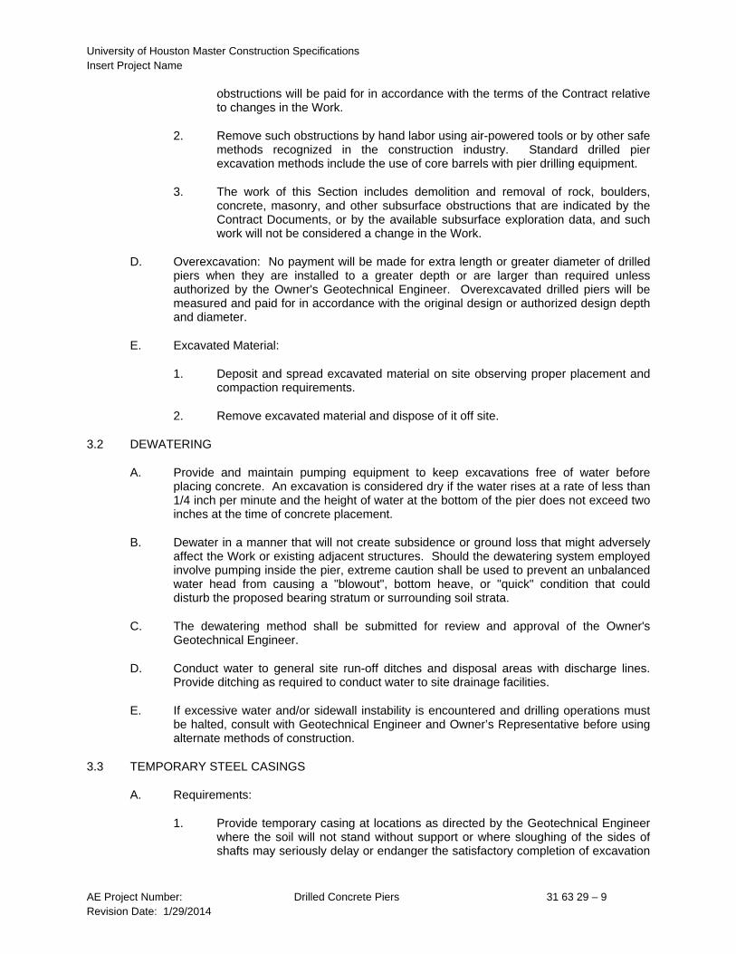
obstructions will be paid for in accordance with the terms of the Contract relative to changes in the Work.
2. Remove such obstructions by hand labor using air-powered tools or by other safe methods recognized in the construction industry. Standard drilled pier excavation methods include the use of core barrels with pier drilling equipment.
3. The work of this Section includes demolition and removal of rock, boulders, concrete, masonry, and other subsurface obstructions that are indicated by the Contract Documents, or by the available subsurface exploration data, and such work will not be considered a change in the Work.
D. Overexcavation: No payment will be made for extra length or greater diameter of drilled piers when they are installed to a greater depth or are larger than required unless authorized by the Owner's Geotechnical Engineer. Overexcavated drilled piers will be measured and paid for in accordance with the original design or authorized design depth and diameter.
E. Excavated Material:
1. Deposit and spread excavated material on site observing proper placement and compaction requirements.
2. Remove excavated material and dispose of it off site.
3.2 DEWATERING
A. Provide and maintain pumping equipment to keep excavations free of water before placing concrete. An excavation is considered dry if the water rises at a rate of less than 1/4 inch per minute and the height of water at the bottom of the pier does not exceed two inches at the time of concrete placement.
B. Dewater in a manner that will not create subsidence or ground loss that might adversely affect the Work or existing adjacent structures. Should the dewatering system employed involve pumping inside the pier, extreme caution shall be used to prevent an unbalanced water head from causing a "blowout", bottom heave, or "quick" condition that could disturb the proposed bearing stratum or surrounding soil strata.
C. The dewatering method shall be submitted for review and approval of the Owner's Geotechnical Engineer.
D. Conduct water to general site run-off ditches and disposal areas with discharge lines. Provide ditching as required to conduct water to site drainage facilities.
E. If excessive water and/or sidewall instability is encountered and drilling operations must be halted, consult with Geotechnical Engineer and Owner’s Representative before using alternate methods of construction.
3.3 TEMPORARY STEEL CASINGS
A. Requirements:
1. Provide temporary casing at locations as directed by the Geotechnical Engineer where the soil will not stand without support or where sloughing of the sides of shafts may seriously delay or endanger the satisfactory completion of excavation

University of Houston Master Construction Specifications Insert Project Name
AE Project Number: Drilled Concrete Piers 31 63 29 – 10 Revision Date: 1/29/2014
and placement of concrete. Also provide temporary casing at locations as directed by the Geotechnical Engineer to seal off the inflow of water into the excavation.
2. The Contractor shall have immediately available for use on the job an ample supply of casing for each size that will be required for use in the shafts and shall provide additional amounts, as required, to ensure the orderly progress of the job.
3. Such casing may be in short pieces but with jointing devices of sufficient strength that assembled sections of casing may be pulled complete as concrete is placed, or immediately thereafter. Provide casing of sufficient strength to withstand handling stresses, concrete pressure, and surrounding earth and/or fluid pressures. Make diameter of excavation in relation to diameter of casing such as to create a minimum of void space outside of casing. Provide casing with a minimum outside diameter equal to normal outside diameter of drilled foundations.
B. Delivery, Handling, and Storage of Casing
1. Deliver casing to site in undamaged condition.
2. Handle and protect casing to maintain diameter within plus or minus two percent.
C. Casing Withdrawal: Unless otherwise approved by the Owner’s Representative, all temporary casing shall be removed from shafts as concrete is placed or immediately thereafter, and in such a manner as to prevent sloughing material from dropping to the bottoms of shafts or falling on top of freshly placed concrete. Casings shall be pulled in a single continuous smooth operation without sudden jerks or impact. Maintain head of concrete above the bottom of the casing that exceeds the soil and water pressure at all times during casing withdrawal. Do not vibrate concrete internally before the casing is withdrawn. A vibratory casing extractor may be used. Do not withdraw casing after the concrete has attained initial set. The casing withdrawal and concreting operations shall be observed by the Geotechnical Engineer.
3.4 REINFORCING STEEL PLACEMENT
A. Before placing, clean reinforcing steel and dowels of loose rust, scale, dirt, grease and other material that could reduce or destroy bond.
B. Fabricate and erect reinforcing cages in shafts as one continuous unit using inner ring reinforcing guide. Place reinforcement accurately and symmetrically about axis of hole and hold securely in position during concrete placement. The Contractor shall verify depths of drilled piers prior to cutting and tying reinforcing steel cages. Reinforcing steel shall be delivered to the site in standard 60-foot lengths and cut as required. Splice no more than 33% of the bars at any one location, alternating spliced and unspliced bars in a symmetrical pattern. Splices shall be 30 bar diameter compression splices for bars #11 and smaller and mechanical end bearing compression splices for #14 and #18 bars unless noted otherwise on the drawings. See drawings for additional splice information. The Contractor shall be responsible for adding additional reinforcing steel ties or spirals as required to ensure stability of cage and maintenance of shape and configuration as required for proper lifting, handling, and placement.
C. Provide cover to reinforcing steel of not less than 3 inches where exposed to soil and not less than 4 inches in temporarily cased piers. Provide spacer devices to maintain side

University of Houston Master Construction Specifications Insert Project Name
AE Project Number: Drilled Concrete Piers 31 63 29 – 11 Revision Date: 1/29/2014
and bottom cover. Devices shall be installed in accordance with manufacturer’s instructions.
D. Permissible reinforcing steel upward vertical movement during casing withdrawal shall be no greater than 6 inches. Downward movement should not exceed 6 inches for every 20 feet of shaft length.
E. Use templates to set anchor bolts, leveling plates and other accessories furnished under work of other sections. A qualified and licensed Engineer/Land Surveyor shall determine the plan location and elevation of such devices. Provide spacers (capable of sliding on any temporary casings required), blocking and holding devices to maintain required position during concrete placement.
F. The General Contractor shall protect exposed ends of dowels and anchor bolts from mechanical damage and exposure to weather by wrapping and taping with polyethylene or other suitable material.
3.5 CONCRETE PLACEMENT
A. General:
1. Fill drilled piers with concrete immediately after inspection and approval by the Geotechnical Engineer or other authorized inspector. Use protection sheets (cut out to receive concrete) over excavation openings, extending at least 12" beyond edge. Complete the excavation and concrete placement in uncased excavations before the end of the workday unless the Architect/Engineer and Geotechnical Engineer grants permission to do otherwise in writing.
2. Place concrete continuously and in a smooth flow without segregating the mixed materials.
3. Place concrete by means of bottom discharge bucket, flexible drop chute, elephant trunk hopper, concrete pump, or tremie. Free fall of concrete may be used if provided for in concrete mix design and provided it is directed through a hopper or chute such that fall is down center of shaft without hitting sides or reinforcing steel. Free fall of concrete is not permitted for depths greater than the smaller of 20 times the shaft diameter or 60 feet.
4. Place concrete in-the-dry if at all possible. If water occurs, and it is impracticable to dewater drilled pier excavation, and reasonable attempts to seal off water flow have failed, allow water level to attain its normal level and place concrete by tremie method or by concrete pumping. Other methods of depositing concrete underwater may only be used if approved by Architect/Engineer.
5. Stop concrete placement at cut-off elevation shown, screed level, and apply a scoured, rough finish. Where cut-off elevation is above ground elevation, form top section above grade and extend shaft to required elevation.
6. Provide mechanical vibration for consolidation of at least top 5' of each shaft but only after any temporary casing is pulled or when casing is permanent.
7. Interrupted placing operations of over one hour duration will require a cold joint installation as follows. Leave resulting shaft surface approximately level. At resumption of concrete placing, clean off surface laitance, roughen as required,

University of Houston Master Construction Specifications Insert Project Name
AE Project Number: Drilled Concrete Piers 31 63 29 – 12 Revision Date: 1/29/2014
and slush with a 1-to-1 cement grout or commercial bonding agent before remainder of concrete is placed. Intentional cold joints will not be permitted.
8. Concrete shall not be placed in adjacent drilled piers located within three center-to-center shaft diameters of each other until concrete has cured a minimum of 6 hours.
9. Aluminum pipe or equipment shall not be used for placing concrete.
B. Tremie Method:
1. The drilled shafts shall be filled with concrete by the use of a tremie or concrete pump, sealed at the bottom, extending from above the ground surface to the bottom of the drilled shaft. Inspection of the empty tremie on the bottom may be requested of the Contractor by the Owner's authorized inspector. With the sealed tremie on the bottom of the shaft, the tube shall be filled to the top extending above the ground. The filled tremie shall be picked up approximately one (1) foot off the bottom of the shaft to allow the weight of the concrete to displace the seal at the bottom of the tremie. At no time is the tremie to be pulled to such a height as to clear the surface of the concrete already placed in the shaft. All concrete shall be poured through the now open tremie with care taken to maintain a sufficient head of concrete to completely displace all water and suspended cuttings of material and to provide sufficient pressure so as to prevent reduction in pile diameter by earth pressure on the fresh concrete. The concrete in each pile shall be carried above cut-off elevation and then dipped out while fresh to cut-off elevation.
2. All concrete shall be deposited through the tremie or pumpline so as to provide a continuous flow, without aggregate segregation, from bottom to top of pile. The production and delivery of the ready-mixed concrete shall be such that not more than 45 minutes shall elapse between the depositing of successive batches of concrete to ensure a monolithic unit of concrete. No deviation from this method will be acceptable.
3. Should the surface of the concrete in the shaft be breached by the tremie or pumpline, the tube shall immediately be withdrawn from the hole, re-sealed and re-lowered below the surface of the concrete, and pouring operations re-started. Should the Owner's authorized inspector deem it necessary, the Contractor shall instead retrieve the reinforcing steel cage, redrill the shaft to reopen the hole, and begin the concreting operations from the bottom of the pier shaft.
4. If the Owner's authorized inspector has reason to suspect that the concrete was breached by the tremie or pumpline or that the pier, for any other reason, may contain extraneous material or otherwise fail the specifications, he may order the pier cored for inspection and/or testing. If the core recovery and/or test results indicate non-compliance with the specifications, the Contractor shall bear the expense of the investigation and/or testing and shall also, at no cost to the Owner, install proper additional construction as required by the Architect/Engineer. Should the investigation and/or testing indicate compliance with the specifications the Owner shall bear the cost of such investigation and/or testing.
C. Hot and Cold Weather Placement: Refer to Part II.
University of Houston Master Construction Specifications Insert Project Name
AE Project Number: Drilled Concrete Piers 31 63 29 – 13 Revision Date: 1/29/2014
3.6 SLURRY DISPLACEMENT METHOD
A. General:
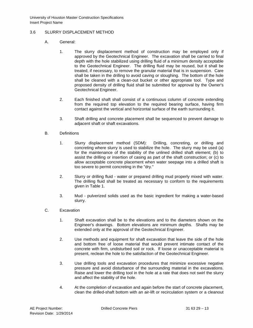
1. The slurry displacement method of construction may be employed only if approved by the Geotechnical Engineer. The excavation shall be carried to final depth with the hole stabilized using drilling fluid of a minimum density acceptable to the Geotechnical Engineer. The drilling fluid may be reused, but it shall be treated, if necessary, to remove the granular material that is in suspension. Care shall be taken in the drilling to avoid caving or sloughing. The bottom of the hole shall be cleaned with a clean-out bucket or other appropriate tool. Type and proposed density of drilling fluid shall be submitted for approval by the Owner's Geotechnical Engineer.
2. Each finished shaft shall consist of a continuous column of concrete extending from the required top elevation to the required bearing surface, having firm contact against the vertical and horizontal surface of the earth surrounding it.
3. Shaft drilling and concrete placement shall be sequenced to prevent damage to adjacent shaft or shaft excavations.
B. Definitions
1. Slurry displacement method (SDM): Drilling, concreting, or drilling and concreting where slurry is used to stabilize the hole. The slurry may be used (a) for the maintenance of the stability of the unlined drilled shaft element; (b) to assist the drilling or insertion of casing as part of the shaft construction; or (c) to allow acceptable concrete placement when water seepage into a drilled shaft is too severe to permit concreting in the "dry."
2. Slurry or drilling fluid - water or prepared drilling mud properly mixed with water. The drilling fluid shall be treated as necessary to conform to the requirements given in Table 1.
3. Mud - pulverized solids used as the basic ingredient for making a water-based slurry.
C. Excavation
1. Shaft excavation shall be to the elevations and to the diameters shown on the Engineer's drawings. Bottom elevations are minimum depths. Shafts may be extended only at the approval of the Geotechnical Engineer.
2. Use methods and equipment for shaft excavation that leave the side of the hole and bottom free of loose material that would prevent intimate contact of the concrete with firm, undisturbed soil or rock. If loose or unacceptable material is present, reclean the hole to the satisfaction of the Geotechnical Engineer.
3. Use drilling tools and excavation procedures that minimize excessive negative pressure and avoid disturbance of the surrounding material in the excavations. Raise and lower the drilling tool in the hole at a rate that does not swirl the slurry and affect the stability of the hole.
4. At the completion of excavation and again before the start of concrete placement, clean the drilled-shaft bottom with an air-lift or recirculation system or a cleanout

University of Houston Master Construction Specifications Insert Project Name
AE Project Number: Drilled Concrete Piers 31 63 29 – 14 Revision Date: 1/29/2014
bucket equipped with a one-way flap gate that prevents spoils in the bucket from reentering the shaft.
5. For piers designed without end bearing, the accumulated sediment at the bottom of the pier, measured by sounding with a weighted tape just prior to concreting, shall be less than 6 inches. If greater, reclean the hole to the satisfaction of the Geotechnical Engineer.
6. All spoil and excavated materials shall be kept away from each open shaft excavation to avoid contamination of the excavation after final cleanout.
7. Excavated materials shall be stockpiled or disposed of in areas designated by the Owner's representative.
8. Excavated materials temporarily placed at other locations for the convenience of the Contractor will be allowed only with written approval of the Owner's representative and shall finally be removed and placed within designated disposal areas.
D. PROVISIONS FOR OBSERVATION
1. The Contractor shall cooperate with the Owner and design team to ensure the expeditious and safe observation of the shaft excavations.
2. If the Geotechnical Engineer determines that the material at the bottom of any excavation is unsatisfactory, additional excavation or other corrective action shall be made as directed by the Geotechnical Engineer.
3. If additional excavation is required, the shaft bottom shall be drilled again and observed as described above. This procedure shall be repeated until a bearing material is reached that is approved by the Geotechnical Engineer.
E. SLURRY REQUIREMENTS
1. The mud slurry shall consist of a stable colloidal suspension of pulverized solids thoroughly mixed with water so that the properties specified in Table 1 are maintained. Attapulgite and bentonite shall meet API Specification 13A, Section 3, "Oil-Well Drilling-Fluid Material" dated March 1981. The type of mud used will depend on the subsurface conditions and mixing water character. The water used to mix the slurry shall be clean, drinkable, fresh water, obtained from sources approved by the Owner's Representative. Any physical or chemical treatment to the water or slurry that is considered necessary to have the slurry meet the specifications is the responsibility of the drilled shaft contractor. A written certificate shall be supplied to the Architect/Engineer by the mud supplier specifying the quality and yield for each shipment of mud received. A test report from the supplier giving the physical and chemical properties of the mud shall be supplied to the Architect/Engineer at the start of the work.
2. Water may be used in place of mixed mud slurry, subject to the approval of the Geotechnical Engineer on a pier-by-pier basis except for end bearing piers.
3. For shafts with endbearing greater than or equal to 25% of the total allowable capacity as shown on the structural drawings, the mud slurry sand content shall be limited to 4%.

University of Houston Master Construction Specifications Insert Project Name
AE Project Number: Drilled Concrete Piers 31 63 29 – 15 Revision Date: 1/29/2014
4. The mud slurry shall be mixed in mud tanks on-site or arrive at the site premixed. The mud slurry shall be mixed, stored, and transported using equipment made for these purposes. Combining or mixing slurry in the shaft shall be not permitted.
5. The in-hole slurry shall meet the specifications prior to concreting. Replace or clean, recirculate, and remove sand from, the slurry to maintain the required slurry properties. Recycling of slurry is permitted provided that the recycled slurry satisfies the specified requirements. Submit to the Owner’s Representative a written record of test results for each drilled pier.
6. The Contractor shall perform testing of the slurry according to the test methods prescribed in Table 1 and shall record the results for quality control purposes. Provide all field test equipment as required. The drilled-pier contractor shall have available at the site a slurry sampler capable of obtaining slurry samples at any depth within the drilled pier excavation. Slurry shall be sampled and tested in the mud tank and from samples recovered within 1 ft. from the bottom of each drilled shaft.

University of Houston Master Construction Specifications Insert Project Name
AE Project Number: Drilled Concrete Piers 31 63 29 – 16 Revision Date: 1/29/2014
TABLE 1
SLURRY SPECIFICATIONS Range of Item to be Results Test Measured at 20°C Method Density, (pcf)** ASTM D 4380 For slurry 1 ft from pier bottom (Mud Balance) Mineral Slurries a. No end bearing 85 Max. b. With end bearing 70 Max. Polymer Slurry 64 Max. Marsh Funnel Viscosity, (sec./qt) API-RP13B-1* Section 2 a. Mineral Slurry 25 to 60 (Marsh funnel & CUP) b. Polymer Slurry 40 to 90 Sand Content by Volume (%), ASTM D 4381 before concreting, for slurry 1 ft (Sand screen set) from pier bottom Mineral Slurries a. No end bearing 20 Max. b. With end bearing 4 Max. Polymer Slurry 1 Max. pH, during excavation 7 to 12 ASTM D 4972 * Reference Test Method is American Petroleum Institute (API), Spec. 13B, Eighth Edition, April
1980, issued by American Petroleum Institute - Production Department - 211 N. Ervay, Suite 1700, Dallas, Texas 75201.
** The density of the mud slurry shall not be less than what is needed to drill the shaft.

University of Houston Master Construction Specifications Insert Project Name
AE Project Number: Drilled Concrete Piers 31 63 29 – 17 Revision Date: 1/29/2014
F. Installation Method
1. Where pre-drilled piers are to be installed below the groundwater level or in caving and sloughing soils, and the procedure is approved by the Geotechnical Engineer and the Owner’s Representative, use a premixed mud slurry to stabilize the excavation. Maintain the slurry level in the excavation above any unstable zones a sufficient distance to prevent caving or sloughing of those zones but no less than 5 feet above the groundwater level.
2. Set temporary surface casing to contain the slurry, unless waived by the Owner’s Representative.
G. Concreting Method
1. Concreting of the drilled pier shall be completed the same day that the excavation is complete. If this is not possible, the excavation will be required to be redrilled, cleaned, and slurry tested before concreting.
2. Place concrete by tremie method or by pumping. Use tremie or pump pipes made of steel and with watertight joints. Use tremie pipe with a minimum diameter of 8 inches or pump pipe with a minimum diameter of 4 inches.
3. Use a capped or pig-plugged tremie or pump pipe inserted and seated in the excavation at the bottom of the pier prior to commencement of the concrete placement.
4. If a capped pipe is used, use tremie or pump pipe with a seal consisting of a bottom plate, or a device acceptable to the Geotechnical Engineer, that seals the bottom of the pipe until the pipe reaches the hole bottom. Place enough concrete in the pipe to prevent the flow of slurry into the tremie pipe when it is lifted off the bottom.
5. If a pig is used, set the open tremie pipe loosely on the bottom. Insert the pig at the top and then place concrete pushing the pig ahead, separating the concrete from the slurry. Take care to ensure that the pig is properly sized to fit in the pipe, and keep the concrete separate from the slurry so that all slurry is expelled from the pipe during the initial charging process. When the pipe is fully filled with concrete, lift the pipe off the bottom the minimum amount needed to start the concrete flowing. Once concrete flow has started, place concrete into tremie at a fast enough rate to maintain a positive head of concrete inside pipe relative to slurry level outside pipe.
6. Embed tremie of pump pipe sufficiently in concrete to maintain seal throughout concrete placement to prevent re-entry of slurry suspension into the pipe. Provide minimum embedment of 5 feet. If the seal is lost, withdraw pipe, replace the seal, and re-start tremie using a capped tremie or capped pump pipe.
7. Displace out of the pier or remove from the pier the first portion of concrete that comes to the top of the pier that contains concrete contaminated with slurry until acceptable concrete is visible. Add or remove concrete to specified cutoff level.
8. Raise or lower the tremie pipe in an acceptable manner that does not break the seal and does not cause channelization or segregation.

University of Houston Master Construction Specifications Insert Project Name
AE Project Number: Drilled Concrete Piers 31 63 29 – 18 Revision Date: 1/29/2014
9. Pump the displaced slurry to holding tanks. Do not allow slurry to spill onto or contaminate the site. Do not use excavated slurry pits, unless accepted by the Owner’s Representative.
10. Do not use aluminum pipe or equivalent for placing concrete.
11. Measure and report actual volume of concrete placed and theoretical volume versus depth at depth intervals not exceeding the shaft diameter.
3.7 CONSTRUCTION TOLERANCES
A. Plan Location: The tolerance on plan location for the top of the drilled pier shall not be more than 1/24 of the pier diameter or 3" in any direction, whichever is less. If the as-installed shaft is larger than required, the center of the shaft may be taken as the center of a shaft having the required area that lies wholly within the as-installed shaft.
B. Plumbness: Permissible tolerance for plumbness shall be 1.5% of the length. The centers of the top and bottom may be taken as the center of the required area that lies wholly within the as-installed area.
C. Bottom Area: The bottom of the pier shall be essentially horizontal within a tolerance of 1 vertical to 12 horizontal with the area of the bottom bearing not less than 98% of that specified on the drawings.
D. Top Area: The Contractor shall remove excess concrete at the top of the pier beyond the limits of the pier diameter. The pier top diameter shall be the same diameter as the shaft below. Piers extending above the ground surface shall be formed.
E. Concrete Cut-Off Elevation: Concrete cut-off elevation at the pier top shall be plus one inch to minus three inches.
F. Battered Piers: Battered piers shall be installed within 5% of the length from the specified inclination.
G. Anchorage Embedment Tolerance: Vertical and horizontal deviation from design location for individual anchorage components embedded in the pier shall not exceed ± 0.5 inches.
H. If any of the above tolerances are exceeded, the Architect/Engineer shall immediately be notified to evaluate the eccentricity in the pier and recommend corrective measures. The cost of re-engineering and corrective construction shall be borne by the Contractor.
3.8 PERMANENT STEEL CASINGS
A. Requirement: Provide permanent steel casings where shown on the drawings of sufficient strength to withstand handling stresses, concrete pressure, and surrounding earth and/or fluid pressures. Provide casings with minimum outside diameter equal to nominal outside diameter of shaft. Wall thickness shown on the drawings is a minimum required for design purposes. The Contractor is responsible for increasing thickness as required for the installation process.
B. Steel Pipe Casings: Provide steel pipe casings as shown on the drawings delivered in sections of any convenient length. Connect sections by continuous complete penetration welds performed according to AWS standards by certified welders during placement into drilled pier shaft excavation. Splice location and details shall be submitted for approval on steel pipe casing shop drawings.

University of Houston Master Construction Specifications Insert Project Name
AE Project Number: Drilled Concrete Piers 31 63 29 – 19 Revision Date: 1/29/2014
Design bottom edge of lowest casing section to provide cutting shoe for penetrating into rock strata and affecting water seal.
C. Corrugated Steel Casings: Provide corrugated steel casings formed of galvanized or bituminous-coated steel sheets. Corrugated steel casings may be delivered in any convenient section of panel, with sections or panels field connected in accordance with manufacturer's instructions.
D. Installation: Install permanent steel casing as excavation work progresses to ensure stability of drilled pier shaft walls. Remove and replace or repair casings which are damaged during installation and which could impair strength or efficiency of completed drilled pier.
E. Fill the void space between permanent casing and shaft excavation or between permanent liner and temporary casing with fluid grout by means of grout pipe and pump pressure as required to achieve uniform void filling.
3.9 INSPECTIONS AND TESTS FOR DRILLED PIER EXCAVATIONS
A. Verification of Design: Bottom elevations, bearing and/or skin friction capacities and lengths of drilled piers as shown on the drawings are estimated from available subsurface data. Actual elevations, pier lengths, and bearing and/or skin friction capacities will be determined by the Geotechnical Engineer from conditions found in the excavations.
For piers bearing on rock, a rock core shall be taken for a depth equal to one pier diameter below the bottom of the pier for observation and possible testing by the Geotechnical Engineer to confirm rock quality below the bearing elevation.
B. Notification of Architect/Engineer: If field conditions differ from the data and design recommendations outlined in the Geotechnical Report, the Geotechnical Engineer shall notify the Architect/Engineer immediately.
C. Additional Tests: Additional tests may be required by the Geotechnical Engineer to determine new design criteria. Such tests shall be made as quickly as possible so as not to delay the concreting operations any longer than absolutely required.
D. Observation Requirements: Each drilled pier shall be inspected by the authorized inspector and approved prior to placement of concrete.
E. Cooperation with Testing and Inspection Personnel: The Contractor shall provide facilities as required to assist in the inspection and testing of the excavations, and cooperate with the inspecting and testing personnel to expedite the work.
F. Notification of Observer: The Contractor shall notify the authorized observer at least twelve hours prior to the time the excavation will be ready for inspection. Drilled shaft installation shall not proceed without the authorized observer on site.
G. Personnel Safety: The Contractor shall provide gas testing equipment, protective cage, or temporary casing or shoring of proper diameter, length, and thickness, and all other safety equipment required by law for inspection and testing of drilled piers and to protect workmen and inspectors during hand belling or other operations necessitating entry into shaft.

University of Houston Master Construction Specifications Insert Project Name
AE Project Number: Drilled Concrete Piers 31 63 29 – 20 Revision Date: 1/29/2014
3.10 PIER LOAD TEST
A. Perform load tests to verify design pier lengths and loads. Provide complete testing materials and equipment as required. Notify the Architect/Engineer in ample time before performing tests and perform tests only in the presence of the Owner's Geotechnical Engineer.
B. Test piers, furnished and installed by the Contractor to determine pier criteria, may be located, finished, and become part of foundation system provided they conform to contract requirements and are approved by the Owner's Geotechnical Engineer.
C. Test Piers Required:
Provide one single test pier as directed by the Owner's Geotechnical Engineer.
D. Drilling Test Piers:
1. Use test piers of same size and design as required for the project, and install by the same methods with the same equipment and personnel as will be used in drilling permanent piers.
2. Install test piers at locations and to the depths as specified by the Owner's Geotechnical Engineer.
E. Pier Design Load: Design load for test pier is shown on drawings.
F. Test Loads:
1. Load single test piers to twice required design load for each type pier.
2. Load groups of 3 test piers to 1-1/2 times load capacity of pier group.
G. Pier Load Testing: Pier test shall be at a location as determined by the Geotechnical Engineer and approved by the Architect/Engineer. Test shall be performed under the supervision of the Owner's Geotechnical Engineer. Costs of load tests shall be borne by the Contractor. Design of the load test frame shall be the responsibility of the Contractor. Shop drawings of the load test frame shall be submitted for Architect/Engineer review and shall be prepared under the supervision of and sealed by a registered professional engineer in the state where the project is located. Load and test piers which have been in place sufficient time to allow concrete to attain its 28 day design compressive strength. Determine the load-settlement relationship of test piers under a vertical axial load, complying with ASTM D 1143.
1. Apply loads in increments not exceeding 25% of allowable pier load.
2. Apply test loads either by use of hydraulic jacks or by static loading. Use certified, calibrated jacks to develop the required test loads, maintain them, and release them in continuous operations. Install anchor piers no closer than three pier diameters of larger pier from any test pier or as directed by the Owner's Geotechnical Engineer.
3. Apply test loads so that allowable design load is reached in not less than 8 hours from start of load application. Maintain this load until no measurable settlement is observed in a period of 16 hours or longer, as may be required by local codes

University of Houston Master Construction Specifications Insert Project Name
AE Project Number: Drilled Concrete Piers 31 63 29 – 21 Revision Date: 1/29/2014
having jurisdiction. Do not apply subsequent loads until pier settlement becomes negligible.
4. After satisfactory allowable design load testing, apply additional loads so that total test load is reached in not less than 8 hours. Maintain total load until no measurable settlement is observed in a period of 16 hours, or longer as may be required by local codes having jurisdiction.
5. Measure and record settlement immediately before and after each increment of test load is applied, and immediately before and 24 hours after total load is removed.
6. The test pier will be considered as acceptable for stipulated bearing and/or skin friction capacity if total net settlement, after deducting rebound, does not exceed 0.01" per ton of test load but not greater than 3/4".
H. Test Reports:
1. The Owner's Geotechnical Engineer shall submit copies of the Pier Load Test Report as specified in Submittals section of this specification.
2. Include with the report a record of drilling equipment used.
3. Also include tabular and graphical representation of gross and net settlement of the pier top, relationship of actual load capacity to that predicted, and any recommendations for production pier installation.
3.11 APPROVAL BY THE GEOTECHNICAL ENGINEER
A. Approval by the Owner's Geotechnical Engineer is required on all pier installation criteria and his decision and judgment on pier length, rejection of piers, additional piers required, and all other pier installation and capacity questions shall be final.
3.12 CONTRACT BASIS
A. Basis of Bids: Bids shall be based on number of drilled piers, design length from top elevation to bottom of shaft and diameter of shaft, as shown on drawings. The bid price shall include cost for temporary casing of excavation that may be required.
B. Basis for Payment: Payment for drilled piers will be made on actual net volume of drilled piers in place and accepted. The actual length and shaft diameter may vary to coincide with elevation where satisfactory bearing or friction strata is encountered, and with actual bearing value of bearing strata determined by testing services, and with stability and characteristics of soil strata. Adjustments will be made on net variation of total quantities, based on design dimensions for shafts.
1. There will be no additional compensation for excavation, concrete fill, reinforcing, casings, or other costs due to unauthorized overexcavating shafts. Overexcavated piers will be measured and paid for in accordance with required design or authorized depth. No payment will be made for rejected drilled piers.
2. Prices quoted shall include full compensation for labor, temporary casing, materials, tools, equipment, and incidentals required for excavation, trimming, shoring, casings, dewatering, reinforcement, concrete, and other items for complete installation.
University of Houston Master Construction Specifications Insert Project Name
AE Project Number: Drilled Concrete Piers 31 63 29 – 22 Revision Date: 1/29/2014
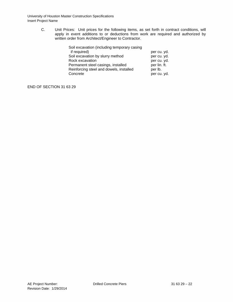
C. Unit Prices: Unit prices for the following items, as set forth in contract conditions, will apply in event additions to or deductions from work are required and authorized by written order from Architect/Engineer to Contractor.
Soil excavation (including temporary casing if required) per cu. yd. Soil excavation by slurry method per cu. yd. Rock excavation per cu. yd. Permanent steel casings, installed per lin. ft. Reinforcing steel and dowels, installed per lb. Concrete per cu. yd.
END OF SECTION 31 63 29