university of groningen flexible needle steering for ... fileinternational journal of medical...
TRANSCRIPT
University of Groningen
Flexible needle steering for computed tomography-guided interventionsShahriari, Navid
IMPORTANT NOTE: You are advised to consult the publisher's version (publisher's PDF) if you wish to cite fromit. Please check the document version below.
Document VersionPublisher's PDF, also known as Version of record
Publication date:2018
Link to publication in University of Groningen/UMCG research database
Citation for published version (APA):Shahriari, N. (2018). Flexible needle steering for computed tomography-guided interventions. [Groningen]:University of Groningen.
CopyrightOther than for strictly personal use, it is not permitted to download or to forward/distribute the text or part of it without the consent of theauthor(s) and/or copyright holder(s), unless the work is under an open content license (like Creative Commons).
Take-down policyIf you believe that this document breaches copyright please contact us providing details, and we will remove access to the work immediatelyand investigate your claim.
Downloaded from the University of Groningen/UMCG research database (Pure): http://www.rug.nl/research/portal. For technical reasons thenumber of authors shown on this cover page is limited to 10 maximum.
Download date: 24-05-2019
4Computed Tomography (CT)-Compatible
Remote Center of Motion Needle Steering
Robot: Fusing CT Images and Electro-
magnetic Sensor Data
N. Shahriari, W. Heerink, T. van Katwijk, E. Hekman,M. Oudkerk, S. Misra
International Journal of Medical Engineering and PhysicsVol. 45, pp. 71-77, July 2017
75

Preface
Chapter 2 presented a novel CT-compatible needle insertion device withtwo degrees-of-freedom, which could insert and rotate a needle. Further-more, an unscented Kalman filter was discussed, which could be used tofuse tracking data from two or more sources. In this chapter further de-velopments of this robotic setup is discussed. A remote-center-of-motionmechanism is developed, which adds two extra degrees-of-freedom to therobot. This enables rotations of the needle around the insertion point, andallow development of new steering algorithms. Furthermore, the unscentedKalman filter which was used to fuse fibre Bragg grating sensor data withultrasound images is modified and adopted here to be used for fusing inter-mittent CT images and real-time electromagnetic tracking data. Therefore,the targeting accuracy can increase with respect to the case in which onlyintermittent CT images were used. In the following chapter, biologicalmotions, which are present in a clinical situations, are considered. A mo-tion profile similar to the liver movement during breathing is applied to aphantom, and a methods to compensate for it is discussed.

4.1 Introduction
Abstract
Lung cancer is the most common cause of cancer-related death, and earlydetection can reduce the mortality rate. Patients with lung nodules greaterthan 10mm usually undergo a computed tomography (CT)-guided biopsy.However, aligning the needle with the target is difficult and the needle tendsto deflect from a straight path. In this work, we present a CT-compatiblerobotic system, which can both position the needle at the puncture pointand also insert and rotate the needle. The robot has a remote-center-of-motion arm which is achieved through a parallel mechanism. A new needlesteering scheme is also developed where CT images are fused with electro-magnetic (EM) sensor data using an unscented Kalman filter. The datafusion allows us to steer the needle using the real-time EM tracker data.The robot design and the steering scheme are validated using three ex-perimental cases. Experimental Case I and II evaluate the accuracy andCT-compatibility of the robot arm, respectively. In experimental Case III,the needle is steered towards 5 real targets embedded in an anthropomor-phic gelatin phantom of the thorax. The mean targeting error for the 5experiments is 1.78±0.70mm. The proposed robotic system is shown tobe CT-compatible with low targeting error. Small nodule size and largeneedle diameter are two risk factors that can lead to complications in lungbiopsy. Our results suggest that nodules larger than 5mm in diameter canbe targeted using our method which may result in lower complication rate.
4.1 Introduction
In the United States and Europe lung cancer screening with low dose com-puted tomography (CT) is recommended for people at high risk or withinclinical trial settings [1,2]. The introduction of lung cancer screening resultsin an increase of detected nodules. The nodules greater than 10mm, andsmall fast-growing nodules would be eligible for clinical work-up, which isoften performed with CT-guided lung biopsy. During this procedure theCT system is used to locate the lung nodule and the needle is advanced intothe subcutaneous tissue of the chest wall incrementally, and a CT scan isacquired after every needle manipulation. The needle is advanced throughthe pleura, when it is properly aligned with the nodule. This can either beperformed by core needle biopsy (CNB) or by fine needle aspiration (FNA).
77

4. Computed Tomography (CT)-Compatible Remote Center of MotionNeedle Steering Robot: Fusing CT Images and Electromagnetic SensorData
In CNB a core is cut through the nodule for pathological analysis, whilein FNA a smaller needle is used to aspirate cell clusters of the nodule, forcytological analysis. CNB is often reported to result in a higher diagnosticperformance, but FNA has a lower complication rate [3, 4].
The consequential increase of pleural punctures increases the chanceof complications such as pneumothorax and pulmonary hemorrhage [5–7].Furthermore, the nodule moves due to respiration, which can result ininaccurate biopsy. Therefore, breathing instructions are given to the patientprior to the procedure to minimize the movement. The patient is asked tohold breath in a consistent fashion if the nodule is close to the diaphragm [8].
Flexible FNA needles tend to deflect from their initial path because oftheir asymmetric tip. This can be used to correct the initial orientation ofapproach during the insertion of the needle by rotating the needle. Thiswill not only decrease the amount of needle manipulations, but also createthe ability to target even small lung nodules.
4.1.1 Related work
Different types of needles and robotic setups have been developed to guidethe needle towards the targeted lesion. Below we discuss some of thesedesigns, and subsequently present our new design and steering scheme.
Needle steering
Flexible needles can be steered in the body in order to target the lesionsaccurately. There exist various needle designs such as bevel-tipped (Fig.4.1, 6O), pre-bent/curved tip [9, 10], concentric tubes [11, 12], pre-curvedstylet [13], programmable bevel [14], tendon-actuated tip [15, 16] and ac-tive needles [17, 18]. Different imaging modalities, such as ultrasound [19],magnetic resonance imaging (MRI) [20] and CT [21], have been used asfeedback to control these needles.
Bevel-tipped needles have a simple design and cause minimal tissuedamage in comparison with the other needles mentioned above. Bevel-tipped needles deflect naturally while inserted into the body due to theforces exerted to the asymmetric tip [22]. This can be used to controlthe trajectory of the needle, and plan a feasible safe path to the target.Abayazid et al. developed a three-dimensional (3D) steering algorithmwhich minimizes the number of rotations, and therefore the tissue damage
78
4.1 Introduction
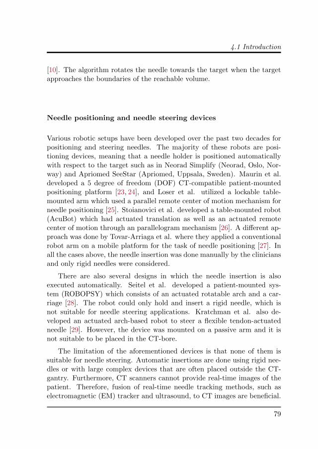
[10]. The algorithm rotates the needle towards the target when the targetapproaches the boundaries of the reachable volume.
Needle positioning and needle steering devices
Various robotic setups have been developed over the past two decades forpositioning and steering needles. The majority of these robots are posi-tioning devices, meaning that a needle holder is positioned automaticallywith respect to the target such as in Neorad Simplify (Neorad, Oslo, Nor-way) and Apriomed SeeStar (Apriomed, Uppsala, Sweden). Maurin et al.developed a 5 degree of freedom (DOF) CT-compatible patient-mountedpositioning platform [23, 24], and Loser et al. utilized a lockable table-mounted arm which used a parallel remote center of motion mechanism forneedle positioning [25]. Stoianovici et al. developed a table-mounted robot(AcuBot) which had actuated translation as well as an actuated remotecenter of motion through an parallelogram mechanism [26]. A different ap-proach was done by Tovar-Arriaga et al. where they applied a conventionalrobot arm on a mobile platform for the task of needle positioning [27]. Inall the cases above, the needle insertion was done manually by the cliniciansand only rigid needles were considered.
There are also several designs in which the needle insertion is alsoexecuted automatically. Seitel et al. developed a patient-mounted sys-tem (ROBOPSY) which consists of an actuated rotatable arch and a car-riage [28]. The robot could only hold and insert a rigid needle, which isnot suitable for needle steering applications. Kratchman et al. also de-veloped an actuated arch-based robot to steer a flexible tendon-actuatedneedle [29]. However, the device was mounted on a passive arm and it isnot suitable to be placed in the CT-bore.
The limitation of the aforementioned devices is that none of them issuitable for needle steering. Automatic insertions are done using rigid nee-dles or with large complex devices that are often placed outside the CT-gantry. Furthermore, CT scanners cannot provide real-time images of thepatient. Therefore, fusion of real-time needle tracking methods, such aselectromagnetic (EM) tracker and ultrasound, to CT images are beneficial.
79

4. Computed Tomography (CT)-Compatible Remote Center of MotionNeedle Steering Robot: Fusing CT Images and Electromagnetic SensorData
Multi-sensor Data fusion
Data fusion has application in many fields and it is used to combine severalsources of measurements to decrease the uncertainty of the resulting infor-mation. Data fusion is used in minimally invasive surgical interventions forseveral imaging modalities and sensors. Ren et. al developed a trackingsystem that fuses EM and inertial sensors in order to track the position andorientation of surgical instruments in the body [30]. An unscented Kalmanfilter was used by Lang et. al to fuse EM tracker data with 2D ultrasoundimages to produce a smooth and accurate 3D reconstruction [31]. Appel-baum et. al developed a system for biopsy of small lesions in which EMtracker data, CT and ultrasound images were fused [32]. A visual feedbackwas provided to the clinician and the insertion was done manually basedon that. Accurate needle steering requires real-time feedback of the needletip pose, which is a limiting factor in CT-guided interventions. We haveproposed fusion of EM tracking data with CT images in order to addressthis limitation by using the real-time EM tracking data to steer the needle.
4.1.2 Contributions
In this work, we have proposed and fabricated a novel CT-compatible robotcapable of steering a bevel-tipped needle, while the needle pose can becontrolled at the insertion point. The robot consists of a needle insertiondevice (NID) and a parallel remote center of motion (RCM) robot arm.The robot is CT-compatible and mainly made of non-metallic materials tominimize the image artifacts. To the best of our knowledge, this is the firstCT-compatible setup which is capable of both positioning and steering aneedle. We discussed the design of the NID in previous work [33]. Inthis paper we present the design of the RCM robot arm, and evaluatethe overall system. This new design allow us to steer a flexible needle ina clinically relevant scheme and to study the effect of base-manipulationon steering of bevel-tipped needles. In addition, a data fusion scheme isdeveloped in order to fuse CT images with EM tracking data using anunscented Kalman filter. This scheme benefits from using real-time dataof EM tracker for steering, while intermittent CT images can correct EMtracking measurement imperfections.
The paper is organized as follows. Section II describes the robot’s designand the developed steering scheme. The experimental setup, plan and
80

4.2 Methods
results are presented in section III. Finally, in section IV, we conclude ourwork and suggest directions for future work.
4.2 Methods
This section presents the design of a CT-compatible robot, and the regis-tration in CT scanner and EM tracker reference frames. CT images arefused with EM-tracker data to provide needle tip pose as feedback to thesteering algorithm.
4.2.1 Design
We have developed a CT-compatible robot for needle steering application,which can both position and insert a needle. The robot consists of a needleinsertion device (NID) and a robotic arm (Fig. 4.2). We discussed thedesign and evaluation of the NID in previous work [33]. Here, we presentthe design of a CT-compatible, 2 degree-of-freedom and remote-center-of-motion (RCM) robotic arm. The NID is attached to the robotic arm as anend-effector. The robot is designed to be used in a CT scanner. CurrentCT scanners (such as Siemens Somatom Sensation 64 (Siemens AG,Munich,Germany) and Brilliance CT (Philips Healthcare, Best, The Netherlands))have a gantry opening of about 820mm. There is approximately 300mmfree space around the abdomen to place the device while a patient is insidethe bore.
The arm can rotate the NID around the insertion point, which is theRCM point. This is achieved through a parallel RCM mechanism for thefirst degree of freedom and a rotating plane for the second degree of freedom.The hinge is mounted at an angle so that the RCM be located exactly onthe phantom surface or patient’s skin . The range of motion for the forwardand backward motion is 50◦ and 35◦, respectively, and 100◦ for sidewaysmotion (Fig. 4.2).
The arm is actuated by two Faulhaber 2232U012SR brushed-DC motors(Faulhaber Group, Schnaich, Germany) equipped with a 22E planetarygearbox with a reduction ratio of 28:1 and an IE2-16 two-channel 16 linesper revolution incremental encoder. Each motor drives a worm gear whichin turn actuates a worm wheel that is directly attached to their respectivehinge. The worm gear/wheel pair are of module 0.5mm with a lead angle
81

4. Computed Tomography (CT)-Compatible Remote Center of MotionNeedle Steering Robot: Fusing CT Images and Electromagnetic SensorData
of 2.23 degrees and have a reduction ratio of 50:1. The arm can only beactuated through the worm gear, thus the worm gear/wheel pair acts asa brake when the motors are turned-off. The motors have rated speed of196 rotations per minute (RPM), and therefore the end-effector speed israted at 3.9 RPM (23.4 degrees/s). The total gear reduction ratio is 1400:1resulting in a total resolution of 22400 lines per revolution or 0.016 degrees.
A Raspberry Pi 2 B (Raspberry Pi foundation, Caldecote, United King-dom) combined with a Gertbot motor controller board (Fen logic limited,Cambridge, United Kingdom) is used to control the robot. The controlleruses pulse-width-modulation (PWM) to set the motor speed, and the PWMis calculated using a proportional-integral-derivative (PID) controller.
4.2.2 Registration
The robot is registered to the CT scanner reference frame using 8 fiducials,which are placed at specific positions on the robot (Fig 4.2). The fiducialsare 5mm spheres made of Aluminium oxide. The locations of the fiducialsare extracted from the CT images using image processing techniques. Theabsolute rotation and translation of the robot is calculated using a least-squares error method by matching the actual fiducials positions with theCAD model [34]. The needle pose is also measured using the EM tracker,and the measurements are used to register the EM tracker in CT scannerreference frame.
4.2.3 Computed Tomography - Electromagnetic data fusion
The EM tracker provides real-time pose of the needle tip, which is advan-tageous for accurate needle steering. On the other hand, CT images areneeded to, first, detect and register the target in the reference frame, andthen, to check the actual needle tip during the insertion. Therefore, theneedle pose is extracted from the CT images, and the EM tracking data isthen fused with the CT data using an unscented Kalman filter (UKF).
UKF is a powerful tool for multi-sensor data fusion [35]. The state es-timation is based on the process model, measurement model and measure-ments, similar to a standard Kalman filter. However, unlike the extendedKalman filter and other Taylor series-based approximation, Jacobian andHessian matrices are not needed for the unscented transformation [36]. The
82
4.2 Methods
UKF uses the unscented transformation for nonlinear sampling and prop-agation of state variables and nonlinear measurements.
The state vector of the tip of the needle is given by
q =[p0t,x p0t,y p0t,z α β γ
]T ∈ R6×1, (4.1)
where p0t = [p0t,x p0t,y p
0t,z]
T ∈ R3×1 is the position of the tip frame (Ψt)represented in the CT scanner frame (Ψct). The process model is definedas follows:
qk = f(qk−1, uk) +wk, (4.2)
where uk ∈ R2×1 is the needle insertion and rotation velocity. The functionf : R7×1 → R6×1 is based on bevel-tipped needle model, and wk ∈ R6×1 isthe process noise vector. The subscript k denotes the discrete time (i.e.,qk = q(tk)). The measurement model is as follows:
zk = h(qk) + vk, (4.3)
where the current estimate of state is related to the measurement vari-able (zk ∈ R12×1) through measurement function h : R6×1 → R12×1. Themeasurement noise (vk ∈ R12×1) is assumed to be white Gaussian whosecovariance depends on measurement accuracy. EM tracker and CT im-ages provide us with the complete pose of the needle in 3D, and zk isthe augmented vector of both measurements. UKF fuses all measurementsto estimate the states of the system (Eq .4.1). The block-diagram of thesystem is demonstrated in Fig. 4.3.
83
4. Computed Tomography (CT)-Compatible Remote Center of MotionNeedle Steering Robot: Fusing CT Images and Electromagnetic SensorData
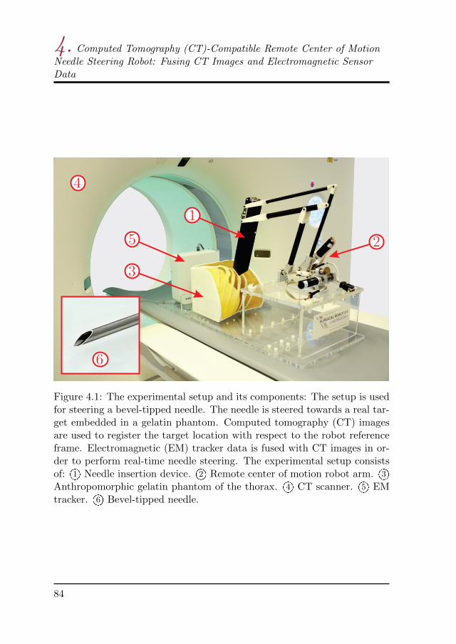
Figure 4.1: The experimental setup and its components: The setup is usedfor steering a bevel-tipped needle. The needle is steered towards a real tar-get embedded in a gelatin phantom. Computed tomography (CT) imagesare used to register the target location with respect to the robot referenceframe. Electromagnetic (EM) tracker data is fused with CT images in or-der to perform real-time needle steering. The experimental setup consistsof: 1O Needle insertion device. 2O Remote center of motion robot arm. 3OAnthropomorphic gelatin phantom of the thorax. 4O CT scanner. 5O EMtracker. 6O Bevel-tipped needle.
84

4.2 Methods
Figure 4.2: Prototype of computed tomography-compatible needle inser-tion setup in initial configuration: 1O Parallel remote center of motionmechanism. 2O Needle insertion device. 3O Worm gear/wheel pair. 4O DCmotors. 5O Remote center of motion, light blue arrow demonstrates side-ways rotation and yellow arrow shows forward/backward rotation of thearm. 6O Aluminum oxide fiducials.
85

4. Computed Tomography (CT)-Compatible Remote Center of MotionNeedle Steering Robot: Fusing CT Images and Electromagnetic SensorData
Fig
ure
4.3
:B
lock
dia
gram
ofth
eex
per
imen
tal
setu
p:
Aco
mp
ute
dto
mog
rap
hy
(CT
)sc
anis
per
form
edp
re-o
per
ati
vely
an
dta
rget
loca
tion
isca
lcu
late
dw
ith
resp
ect
toth
en
eedle
.T
he
NID
pos
eis
mea
sure
du
sin
gel
ectr
omagn
etic
(EM
)tr
ackin
gd
ata
and
also
fid
uci
als
inC
Tim
ages
,an
dE
Mtr
acke
ris
regi
ster
edto
the
CT
scan
ner
.T
he
stee
rin
gis
div
ided
into
fou
req
ual
segm
ents
bas
edon
the
inse
rtio
nle
ngth
.R
eal-
tim
eE
Mtr
ack
ing
dat
ais
use
dto
stee
rth
eb
evel
-tip
ped
nee
dle
.A
tth
een
dof
each
segm
ent,
an
ewC
Tsc
an
isp
erfo
rmed
and
nee
dle
tip
pos
eis
calc
ula
ted
from
CT
imag
esu
sin
gim
age
pro
cess
ing
tech
niq
ues
.T
he
nee
dle
pos
efr
omE
Mtr
ack
eran
dC
Tim
ages
are
fuse
du
sin
gan
un
scen
ted
Kal
man
filt
er(U
KF
).T
he
filt
ered
dat
ais
use
dto
up
date
the
nee
dle
stee
rin
gal
gori
thm
.T
hes
est
eps
are
rep
eate
dth
ree
tim
esunti
lth
en
eed
lere
ach
esit
sfi
nal
pos
itio
n.
86
4.3 Experiments
4.3 Experiments
This section describes the experiments performed to evaluate the system.The experimental setup and plan are explained below, followed by the re-sults at the end of this section.
4.3.1 Experimental setup
The experimental setup shown in Fig. 4.4 is used to validate the design andthe proposed steering algorithm. It consists of the NID, controllers, an EMtracker and a CT scanner. The CT scanner used in the experiments is theSiemens Somatom Force (Siemens AG, Munich , Germany). The settingsare the defaults used for abdomen scan, which are a tube voltage of 90KVP,tube current of 234mAs, pixel spacing of 0.96mm, slice thickness of 0.5mmand convolution kernel of Br40d.
A needle with the diameter of 0.55mm (23.5 gauge) equipped with a5 DOF EM sensor is used to track the needle tip with the EM trackingsystem. The needle tip pose is measured 20 times per second using anAurora v3 EM tracker (Northern Digital Inc., Waterloo, Canada) [37]. TheEM tracking system consists of a field generator, a system control unit anda sensor interface unit. The EM tracker measures the 3D position, pitchand yaw angles. According to the manufacturer, the root mean square(RMS) of the position error is 0.7mm and it is 0.20° for the orientations, ifthe planar field generator is used. The motor encoder is used to measurethe roll angle (rotation about needle axis). The assumption is that thetorsion about the needle axis will cause only minimal offset between the tipand base angles. The needle steering is performed outside of the CT boreto minimize the interference with the EM tracker.
An anthropomorphic gelatin phantom is used in the experiments. Thegelatin phantom is made by mixing 14.9% (by-weight) porcine gelatin pow-der (Dr. Oetker, Ede, The Netherlands) with 85.1% water. This mixtureresults in a phantom with a Young’s modulus of 35kPa [38]. The targetsare spheres of different sizes made of Play-Doh, which is easily mold-ableand gives good contrast on CT.
87
4. Computed Tomography (CT)-Compatible Remote Center of MotionNeedle Steering Robot: Fusing CT Images and Electromagnetic SensorData
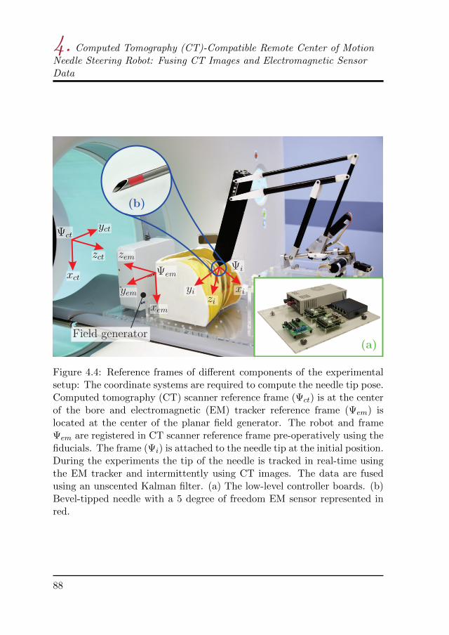
Figure 4.4: Reference frames of different components of the experimentalsetup: The coordinate systems are required to compute the needle tip pose.Computed tomography (CT) scanner reference frame (Ψct) is at the centerof the bore and electromagnetic (EM) tracker reference frame (Ψem) islocated at the center of the planar field generator. The robot and frameΨem are registered in CT scanner reference frame pre-operatively using thefiducials. The frame (Ψi) is attached to the needle tip at the initial position.During the experiments the tip of the needle is tracked in real-time usingthe EM tracker and intermittently using CT images. The data are fusedusing an unscented Kalman filter. (a) The low-level controller boards. (b)Bevel-tipped needle with a 5 degree of freedom EM sensor represented inred.
88

4.3 Experiments
4.3.2 Experimental plan
Three experimental cases are used to evaluate the robot design, interferencewith CT and the proposed steering scheme. The experimental cases are:
Case I) Hardware tests
The robot is positioned in different poses, which are equally distributed inthe work space of the robot. A 6-DOF EM sensor is embedded at the tipof the NID (at the RCM), and the pose of the robot is measured using EMtracker and also CT images. The angular accuracy and the error in RCMare calculated.
Case II) CT noise analysis
The CT-compatibility of the device is evaluated through noise analysis ofCT images. Although signal-to-noise ratio (SNR) is a fundamental conceptin noise analysis, it does not characterize the noise completely [39]. There-fore, the noise-power spectrum (NPS) is commonly used for noise analysisof CT images. NPS is the Fourier transform of the autocorrelation functionwhich characterizes the noise texture and is computed as
NPS(fx, fy) =1
N
N∑i=1
∣∣DFT2D
[Ii(x, y)− Ii
]∣∣2 ∆x∆y
NxNy, (4.4)
where fx and fy are the spatial frequencies in x and y direction (Fig. 4.4),respectively. DFT2D is the 2D discrete Fourier transform, Ii(x, y) is thesignal in ith region of interest (ROI), and Ii is the mean of Ii(x, y). N isthe number of ROIs, and Nx and Ny are number of pixels, and ∆x and ∆y
are the pixel spacing in x and y direction, respectively.A homogeneous cylindrical water phantom is used to compute the NPS.
CT images are acquired of the water phantom with and without the NIDon top of it. Several regions are sampled in the CT images and the Fouriertransform is computed for each region. The Fourier transforms are thenaveraged over all the samples, and the mean 2D NPS is calculated.
Case III) Steering
Steering experiments are performed in an anthropomorphic phantom byfusing the EM tracker data and the CT images. The EM tracker, target
89
4. Computed Tomography (CT)-Compatible Remote Center of MotionNeedle Steering Robot: Fusing CT Images and Electromagnetic SensorData
location and the robot are registered in CT scanner reference frame at thebeginning of each experiment.
The insertion length is divided into 4 equal segments. The needle issteered using the the real-time feedback from the EM tracker. The steeringalgorithm is based on the method proposed by Abayazid et al. [10]. Theinsertion is paused at the end of each segment, and a new CT scan isperformed. The needle pose is extracted from the CT images and it isfused with the EM tracker data. This procedure is repeated for three moretimes until the needle reaches its final position. It is possible to increasethe number of steps, which will result in more accurate steering but alsomore radiation dose.
4.3.3 Results
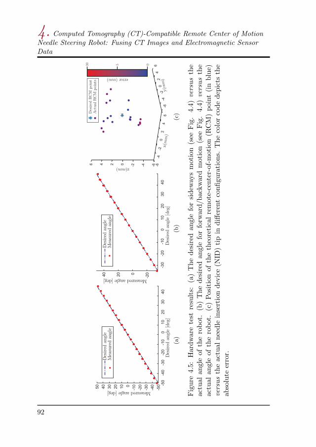
We present the results for the three experimental cases in this section.In the experimental Case I, each degree of freedom of the robot arm istested individually. Each set-point is reached 5 times from both direc-tions, in order to evaluate the accuracy and check for any hysteresis ef-fect. Fig. 4.5-(a,b) show the measured angular positions of the NID ver-sus desired set-points. The average angular errors are 0.98±0.62◦ and0.36±0.48◦ for sideways and forward/backward motion (Fig. 4.2), respec-tively. Fig. 4.5-(c) shows position of the theoretical RCM point versus theactual NID tip in different configurations. The RCM error is calculated asthe absolute distance between the desired and actual RCM position in 3Dspace. The mean of RCM error is 4.37±1.87mm. The NPS is calculated inthe experimental Case II using 12 ROIs. The robot is positioned straightup on top of the water phantom, which is the position that causes the max-imum artifact, in order to calculate the NPS for the worst-case scenario. Itis shown in Fig. 4.6-a that the robot introduces minimal additional noise tothe images and it is visible also in the 2D NPS shown in Fig. 4.6-c,d. The2D NPS shows that the artifacts correspond to specific spatial frequencies(the bright horizontal area), which depends on the location of the robotwith respect to the phantom.
In experimental Case III, the needle is steered towards 5 real targets.The targets are spheres with a radius ranging between 1.98mm and 8.65mmand the insertion depth ranging between 55.99mm and 101.08mm. Theneedle is steered towards the center of the targets and the experiment is
90
4.3 Experiments
evaluated by calculating the absolute distance between the target posi-tion and needle tip position in 3D space. The mean targeting error is1.78±0.70mm. The results show an improvement with respect to our re-cent work, where we demonstrated a targeting error of 1.94±0.63mm usingonly CT images for a virtual target [33]. This comparison demonstratesthat the proposed data fusion scheme is effective and results in approxi-mately 10% less targeting error. The needle trajectory is shown in Fig. 4.7for all 5 experiments.
91
4. Computed Tomography (CT)-Compatible Remote Center of MotionNeedle Steering Robot: Fusing CT Images and Electromagnetic SensorData
(a)
(b)
(c)
Fig
ure
4.5:
Har
dw
are
test
resu
lts:
(a)
Th
ed
esir
edan
gle
for
sidew
ays
mot
ion
(see
Fig
.4.
4)versus
the
actu
alan
gle
of
the
rob
ot.
(b)
Th
ed
esir
edan
gle
for
forw
ard
/bac
kw
ard
mot
ion
(see
Fig
.4.
4)versus
the
actu
alan
gle
ofth
ero
bot
.(c
)P
osit
ion
ofth
eth
eore
tica
lre
mot
e-ce
nte
r-of
-mot
ion
(RC
M)
poin
t(i
nb
lue)
versus
the
actu
aln
eedle
inse
rtio
nd
evic
e(N
ID)
tip
ind
iffer
ent
con
figu
rati
ons.
Th
eco
lor
cod
ed
epic
tsth
eab
solu
teer
ror.
92

4.4 Discussion and future work
Table 4.1: Experimental results for Case III: Computed tomography imagesare fused with electromagnetic tracking data using an unscented Kalmanfilter. The needle is steered towards 5 real target. The targets are placedat different locations and depths (see also Fig. 4.7). The error is calculatedas the absolute 3D distance between the needle tip and center of the target.
# Target x(mm) Target y(mm) Target z(mm) Target size(mm) Error
1 0.22 11.08 81.83 8.65 2.06
2 14.89 −3.88 101.08 1.98 2.37
3 0.96 10.64 89.25 8.15 0.96
4 −3.38 8.54 79.15 5.60 2.43
5 −1.70 5.88 55.99 3.93 1.09
mean error 1.78±0.7
4.4 Discussion and future work
In this paper we have presented a novel CT-compatible robotic setup forsteering a bevel-tipped flexible needle. The robot consists of the NID anda 2 DOF remote-center-of-motion arm. The robot arm orients the NID atthe needle insertion point and the needle is then steered using the NID. Anew steering scheme is also presented where the needle tip pose is trackedusing real-time EM tracking data and intermittent CT images. EM andCT data are fused using an unscented Kalman filter every time a new CTscan is performed. The EM tracker and CT scanner are registered pre-operatively, and CT images are used to register the target position in thereference frame.
4.4.1 Discussion
Several experiments are conducted to evaluate the accuracy and the CTcompatibility of the robot. The results of the first experimental case showthat, in the worst case, the robot arm can have an orientation error of about2 degrees. The error is small near the zero-configuration (Fig. 4.2) and itincreases as the robot moves towards the extreme configurations, such asfully-extended or fully-retracted arm. In theory, the RCM should be onestationary point, however, this is not the case during the experiments. Themain cause of the error in positioning of the robot arm and the RCM
93

4. Computed Tomography (CT)-Compatible Remote Center of MotionNeedle Steering Robot: Fusing CT Images and Electromagnetic SensorData
Figure 4.6: Computed tomography (CT) noise analysis: The noise powerspectrum is computed for a homogeneous cylindrical water phantom.(a) The needle insertion device (NID) is on top of phantom. (b) Thephantom is in the CT scanner without the NID. (c-d) The 2D noise powerspectrum (NPS) calculated for case (a) and (b), respectively, using 12 ROIshown by dashed-red squares. The artifacts caused by the NID are limitedand do not interfere with tracking the needle in the CT images.
94
4.4 Discussion and future work
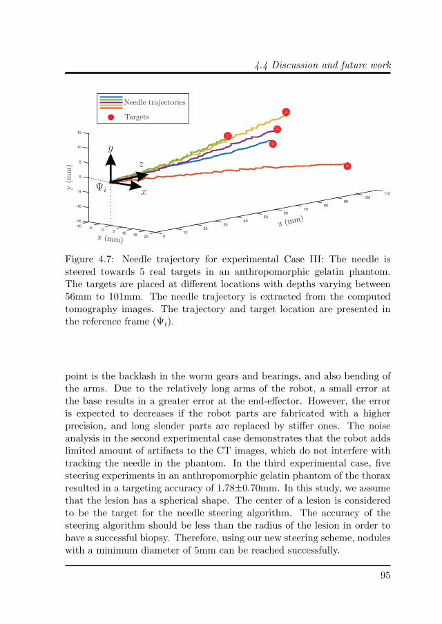
Figure 4.7: Needle trajectory for experimental Case III: The needle issteered towards 5 real targets in an anthropomorphic gelatin phantom.The targets are placed at different locations with depths varying between56mm to 101mm. The needle trajectory is extracted from the computedtomography images. The trajectory and target location are presented inthe reference frame (Ψi).
point is the backlash in the worm gears and bearings, and also bending ofthe arms. Due to the relatively long arms of the robot, a small error atthe base results in a greater error at the end-effector. However, the erroris expected to decreases if the robot parts are fabricated with a higherprecision, and long slender parts are replaced by stiffer ones. The noiseanalysis in the second experimental case demonstrates that the robot addslimited amount of artifacts to the CT images, which do not interfere withtracking the needle in the phantom. In the third experimental case, fivesteering experiments in an anthropomorphic gelatin phantom of the thoraxresulted in a targeting accuracy of 1.78±0.70mm. In this study, we assumethat the lesion has a spherical shape. The center of a lesion is consideredto be the target for the needle steering algorithm. The accuracy of thesteering algorithm should be less than the radius of the lesion in order tohave a successful biopsy. Therefore, using our new steering scheme, noduleswith a minimum diameter of 5mm can be reached successfully.
95
4. Computed Tomography (CT)-Compatible Remote Center of MotionNeedle Steering Robot: Fusing CT Images and Electromagnetic SensorData
4.4.2 Future work
Although the current study is a step towards bringing needle steering intoclinical practice, we believe it can be further improved in future work. Themain limitation of the current design is lack of translational motion. Actu-ated fine 3D translation of the RCM point can help positioning the robotaccurately at the insertion point. Biological tissues are inhomogeneouswhich cause the needle to deflect differently, specially if the needle triesto puncture the chest wall or vessels. Therefore, experiments in cadaverare necessary in order to validate the system for clinical use. Furthermore,physiological movements need to be considered and compensated for inthe system. Finally, pre-operative path planning can help in defining thesuitable insertion location and initial pose of the needle.
96
References
[1] V. A. Moyer, “Screening for lung cancer: U.S. preventive servicestask force recommendation statement,” Annals of Internal Medicine,vol. 160, no. 5, pp. 330–338, 2014.
[2] H. U. Kauczor, L. Bonomo, M. Gaga, K. Nackaerts, N. Peled,M. Prokop, M. Remy-Jardin, O. von Stackelberg, and J.-P. Sculier,“ESR/ERS white paper on lung cancer screening,” European Radiol-ogy, vol. 25, no. 9, pp. 2519–2531, 2015.
[3] X. Yao, M. Gomes, M. Tsao, C. J. Allen, W. Geddie, and H. Sekhon,“Fine-needle aspiration biopsy versus core-needle biopsy in diagnosinglung cancer: a systematic review,” Current Oncology, vol. 19, no. 1,2012.
[4] W. J. Heerink, G. H. de Bock, G. J. de Jonge, H. J. M. Groen,R. Vliegenthart, and M. Oudkerk, “Complication rates of CT-guidedtransthoracic lung biopsy: meta-analysis,” European Radiology, pp. 1–11, 2016, doi:10.1007/s00330-016-4357-8.
[5] K. M. Yeow, I. H. Su, K. T. Pan, P. K. Tsay, K. W. Lui, Y. C. Che-ung, and A. S. B. Chou, “Risk factors of pneumothorax and bleeding:Multivariate analysis of 660 CT-guided coaxial cutting needle lungbiopsies,” Chest, vol. 126, no. 3, pp. 748–754, 2004.
[6] M. F. Khan, R. Straub, S. R. Moghaddam, A. Maataoui, J. Gurung,T. O. F. Wagner, H. Ackermann, A. Thalhammer, T. J. Vogl, andV. Jacobi, “Variables affecting the risk of pneumothorax and intra-pulmonal hemorrhage in CT-guided transthoracic biopsy,” EuropeanRadiology, vol. 18, no. 7, pp. 1356–1363, 2008.
[7] J. P. Ko, J. A. O. Shepard, E. A. Drucker, S. L. Aquino, A. Sharma,B. Sabloff, E. Halpern, and T. C. McLoud, “Factors influencing pneu-mothorax rate at lung biopsy: Are dwell time and angle of pleuralpuncture contributing factors?,” Radiology, vol. 218, no. 2, pp. 491–496, 2001.
97

References
[8] M. D. Cham, M. E. Lane, C. I. Henschke, and D. F. Yankelevitz, “Lungbiopsy: special techniques,” Seminars in respiratory and critical caremedicine, vol. 29, pp. 335–49, 2008.
[9] R. J. Webster, J. S. Kim, N. J. Cowan, G. S. Chirikjian, and A. M.Okamura, “Nonholonomic modeling of needle steering,” The Inter-national Journal of Robotics Research, vol. 25, no. 5-6, pp. 509–525,2006.
[10] M. Abayazid, G. Vrooijink, S. Patil, R. Alterovitz, and S. Misra, “Ex-perimental evaluation of ultrasound-guided 3D needle steering in bio-logical tissue,” International Journal of Computer Assisted Radiologyand Surgery, vol. 9, no. 6, pp. 931–939, 2014.
[11] P. Sears and P. Dupont, “A steerable needle technology using curvedconcentric tubes,” in IEEE/RSJ International Conference on Intelli-gent Robots and Systems, pp. 2850–2856, October 2006.
[12] R. J. Webster III, A. M. Okamura, and N. J. Cowan, “Toward activecannulas: Miniature snake-like surgical robots,” in IEEE/RSJ Inter-national Conference on Intelligent Robots and Systems, pp. 2857–2863,October 2006.
[13] S. Okazawa, R. Ebrahimi, J. Chuang, S. E. Salcudean, and R. Rohling,“Hand-held steerable needle device,” IEEE/ASME Transactions onMechatronics, vol. 10, no. 3, pp. 285–296, 2005.
[14] S. Y. Ko and F. Rodriguez y Baena, “Toward a miniaturized needlesteering system with path planning for obstacle avoidance,” IEEETransactions on Biomedical Engineering, vol. 60, no. 4, pp. 910–917,2013.
[15] R. J. Roesthuis, N. J. van de Berg, J. J. van den Dobbelsteen,and S. Misra, “Modeling and steering of a novel actuated-tip needlethrough a soft-tissue simulant using fiber bragg grating sensors,” inIEEE International Conference on Robotics and Automation (ICRA),pp. 2284–2289, May 2015.
[16] N. J. van de Berg, J. Dankelman, and J. J. van den Dobbelsteen,“Design of an actively controlled steerable needle with tendon actua-
98

References
tion and FBG-based shape sensing,” Medical Engineering & Physics,vol. 37, no. 6, pp. 617–622, 2015.
[17] N. V. Datla and P. Hutapea, “Flexure-based active needle for enhancedsteering within soft tissue,” ASME Journal of Medical Devices, vol. 9,no. 4, pp. 041005–041005–6, 2015.
[18] S. C. Ryu, Z. F. Quek, J. S. Koh, P. Renaud, R. J. Black, B. Moslehi,B. L. Daniel, K. J. Cho, and M. R. Cutkosky, “Design of an opti-cally controlled MR-compatible active needle,” IEEE Transaction onRobotics, vol. 31, no. 1, pp. 1–11, 2015.
[19] M. Abayazid, P. Moreira, N. Shahriari, S. Patil, R. Alterovitz, andS. Misra, “Ultrasound-guided three-dimensional needle steering in bio-logical tissue with curved surfaces,” Medical Engineering & Physics,vol. 37, no. 1, pp. 145 – 150, 2015.
[20] H. Su, G. Cole, and G. Fischer, “High-field mri-compatible needleplacement robots for prostate interventions: Pneumatic and piezoelec-tric approaches,” in Advances in Robotics and Virtual Reality, vol. 26,pp. 3–32, Springer Berlin Heidelberg, 2012.
[21] Y. Zhou, K. Thiruvalluvan, L. Krzeminski, W. H. Moore, Z. Xu, andZ. Liang, “CT-guided robotic needle biopsy of lung nodules with respi-ratory motion – experimental system and preliminary test,” The Inter-national Journal of Medical Robotics and Computer Assisted Surgery,vol. 9, no. 3, pp. 317–330, 2013.
[22] S. Misra, K. B. Reed, B. W. Schafer, K. Ramesh, and A. M. Oka-mura, “Mechanics of flexible needles robotically steered through softtissue,” The International Journal of Robotics Research, vol. 29, no. 13,pp. 1640–1660, 2010.
[23] B. Maurin, B. Bayle, J. Gangloff, P. Zanne, M. de Mathelin, andO. Piccin, “A robotized positioning platform guided by computed to-mography: practical issues and evaluation,” Proceedings of IEEE In-ternational Conference on Robotics and Automation (ICRA), pp. 251–256, 2006.
99

References
[24] B. Maurin, B. Bayle, O. Piccin, J. Gangloff, M. d. Mathelin,C. Doignon, P. Zanne, and A. Gangi, “A patient-mounted robotic plat-form for CT-scan guided procedures,” IEEE Transactions on Biomed-ical Engineering, vol. 55, no. 10, pp. 2417–2425, 2008.
[25] M. H. Loser and N. Navab, “A new robotic system for visually con-trolled percutaneous interventions under CT fluoroscopy,” Proceed-ings of Medical Image Computing and Computer-Assisted Intervention(MICCAI), pp. 887–896, 2000.
[26] D. Stoianovici, K. Cleary, A. Patriciu, D. Mazilu, A. Stanimir,N. Craciunoiu, V. Watson, and L. Kavoussi, “AcuBot: a robot forradiological interventions,” IEEE Transactions on Robotics and Au-tomation, vol. 19, no. 5, pp. 927–930, 2003.
[27] S. Tovar-Arriaga, R. Tita, J. C. Pedraza-Ortega, E. Gorrostieta, andW. A. Kalender, “Development of a robotic FD-CT-guided navigationsystem for needle placement—preliminary accuracy tests,” The Inter-national Journal of Medical Robotics and Computer Assisted Surgery,vol. 7, no. 2, pp. 225–236, 2011.
[28] A. Seitel, C. J. Walsh, N. C. Hanumara, J.-A. Shepard, A. H. Slocum,H.-P. Meinzer, R. Gupta, and L. Maier-Hein, “Development and eval-uation of a new image-based user interface for robot-assisted needleplacements with the Robopsy system,” Proceedings of SPIE, vol. 7261,pp. 72610X–72610X–9, 2009.
[29] L. B. Kratchman, M. M. Rahman, J. R. Saunders, P. J. Swaney,and R. J. Webster III, “Toward robotic needle steering in lungbiopsy: a tendon-actuated approach,” Proceedings of SPIE, vol. 7964,pp. 79641I–79641I–8, 2011.
[30] H. Ren, D. Rank, M. Merdes, J. Stallkamp, and P. Kazanzides,“Multisensor data fusion in an integrated tracking system for en-doscopic surgery,” IEEE Transactions on Information Technology inBiomedicine, vol. 16, no. 1, pp. 106–111, 2012.
[31] A. Lang, P. Mousavi, G. Fichtinger, and P. Abolmaesumi, “Fusion ofelectromagnetic tracking with speckle-tracked 3D freehand ultrasound
100
References
using an unscented Kalman filter,” Proceedings of SPIE, vol. 7265,pp. 72651A–72651A–12, 2009.
[32] L. Appelbaum, L. Solbiati, J. Sosna, Y. Nissenbaum, N. Greenbaum,and S. N. Goldberg, “Evaluation of an electromagnetic image-fusionnavigation system for biopsy of small lesions: Assessment of accuracyin an in vivo swine model,” Academic Radiology, vol. 20, no. 2, pp. 209– 217, 2013.
[33] N. Shahriari, E. Hekman, M. Oudkerk, and S. Misra, “Design andevaluation of a computed tomography (CT)-compatible needle inser-tion device using an electromagnetic tracking system and CT images,”International Journal of Computer Assisted Radiology and Surgery,vol. 10, no. 11, pp. 1845–1852, 2015.
[34] B. K. Horn, H. M. Hilden, and S. Negahdaripour, “Closed-form solu-tion of absolute orientation using orthonormal matrices,” Journal ofthe Optical Society of America A, vol. 5, no. 7, pp. 1127–1135, 1988.
[35] A. Vaccarella, E. de Momi, A. Enquobahrie, and G. Ferrigno, “Un-scented kalman filter based sensor fusion for robust optical and electro-magnetic tracking in surgical navigation,” IEEE Transactions on In-strumentation and Measurement, vol. 62, no. 7, pp. 2067–2081, 2013.
[36] S. J. Julier and J. K. Uhlmann, “Unscented filtering and nonlinearestimation,” Proceedings of the IEEE, vol. 92, pp. 401–422, March2004.
[37] Northern Digital Inc., “Aurora® electromagn-etic tracking system,” [Online]. Available:http://www.ndigital.com/medical/auroratechspecs.php, 2012.
[38] A. Gefen and B. Dilmoney, “Mechanics of the normal woman’s breast,”Technology and Health Care, vol. 15, no. 4, pp. 259–271, 2007.
[39] J. M. Boone, J. A. Brink, S. Edyvean, W. Huda, W. Leitz, C. H. Mc-Collough, and M. F. McNitt-Gray, “Radiation dosimetry and imagequality assessment in computed tomography,” Journal of the Inter-national Commission on Radiation Units and Measurments (ICRU),vol. 12, no. 1, pp. 1–164, 2012.
101

References
102