university of california, irvine - ece.uci.edunader/papers/publications/mpthesis.pdf · theory of...
TRANSCRIPT

UNIVERSITY OF CALIFORNIA,IRVINE
Performance Enhancement of Desktop Multimedia with MultithreadedExtensions to A General Purpose Superscalar Microprocessor
THESIS
submitted in partial satisfaction of the requirements for the degree of
MASTER OF SCIENCE
in Electrical and Computer Engineering
by
Mark Alexander Pontius
Thesis Committee:Professor Nader Bagherzadeh, Chair
Professor Fadi KurdahiProfessor Nikil Dutt
1998

© Mark Pontius, 1998All rights reserved

ii
The thesis of Mark Pontius is approved:
________________________________________
________________________________________
________________________________________Committee Chair
University of California, Irvine1998

iii
TABLE OF CONTENTS
LIST OF FIGURES ......................................................................................VI
LIST OF TABLES ...................................................................................... VII
ABSTRACT OF THE THESIS ................................................................VIII
1. INTRODUCTION....................................................................................... 1
1.1. THE PROBLEM.......................................................................................... 11.2. RELATED WORK ....................................................................................... 21.3. OVERVIEW OF THIS THESIS ....................................................................... 5
2. THEORY OF OPERATION...................................................................... 6
2.1. A MULTITHREADING PRIMER.................................................................... 62.2. BENEFITS AND DRAWBACKS OF MULTITHREADING ................................... 8
2.2.1. Cache Effects .................................................................................... 92.2.2. Instruction Scheduling...................................................................... 92.2.3. Branch Prediction .......................................................................... 112.2.4. Hardware........................................................................................ 122.2.5. Software.......................................................................................... 13
3. ARCHITECTURE .................................................................................... 15
3.1. MULTITHREADED SDSP ARCHITECTURE ............................................... 153.1.1. Block Diagram ............................................................................... 15
Cache / Memory Interface ..........................................................................................................16Fetch Unit...................................................................................................................................17Reorder Buffer / Instruction Window (RBIW)...........................................................................18Functional Units .........................................................................................................................19
3.2. NEW AND MODIFIED UNITS.................................................................... 203.2.1. Thread Control ............................................................................... 203.2.2. Registers ......................................................................................... 21
3.3. INSTRUCTION SET .................................................................................. 213.3.1. New instructions ............................................................................. 22
m_fork(R), m_fork_n(R,N) ........................................................................................................22m_join(R), m_kill_all() ..............................................................................................................22m_exclusive_run(on/off) ............................................................................................................23m_thread_num() .........................................................................................................................23m_read_ipc_reg(R), m_write_ipc_reg(R,D), m_inc_ipc_reg(R), m_dec_ipc_reg(R) ................24
3.3.2. Instructions for simulation only ..................................................... 24m_get_shared(), m_set_shared().................................................................................................24m_quick_run(on/off) ..................................................................................................................25m_marker(N) ..............................................................................................................................26
3.4. SHARING OF MEMORY BETWEEN THREADS ............................................. 26

iv
4. SIMULATOR ............................................................................................ 27
4.1. OVERVIEW ............................................................................................. 274.2. STRUCTURE............................................................................................ 27
4.2.1. Initialization ................................................................................... 284.2.2. Scalar Preprocess Execution.......................................................... 284.2.3. Superscalar Modeling .................................................................... 284.2.4. Thread Scheduling.......................................................................... 294.2.5. User Interface................................................................................. 294.2.6. Statistical Data Generation............................................................ 30
4.3. THREAD MEMORY MANAGEMENT ......................................................... 314.3.1. Shared Memory Model ................................................................... 324.3.2. Private (Non-Shared) Memory Model............................................ 334.3.3. Multiprogram Memory Model........................................................ 34
4.4. ATOMIC TRANSACTIONS......................................................................... 354.5. SIMULATOR INTERNALS ......................................................................... 374.6. SIMULATOR LIMITATIONS AND POTENTIAL IMPROVEMENTS.................... 40
5. BENCHMARKS........................................................................................ 42
5.1. THE MULTIMEDIA DESKTOP ENVIRONMENT .......................................... 425.2. PROGRAMMING ENVIRONMENT .............................................................. 435.3. DISCUSSION OF THE INDIVIDUAL BENCHMARKS AND DATASETS ............. 44
5.3.1. Workload and datasets ................................................................... 445.3.2. Profile............................................................................................. 475.3.3. Properties ....................................................................................... 47
6. RESOURCE ANALYSIS RESULTS...................................................... 54
6.1. DEFAULT PARAMETERS .......................................................................... 546.2. FETCH LIMITS......................................................................................... 58
6.2.1. Fetch Block Size ............................................................................. 586.2.2. Fetch Alignment: Prefetching......................................................... 596.2.3. Branch Prediction .......................................................................... 616.2.4. Instruction Cache ........................................................................... 63
6.3. DATA AND PIPELINE LIMITS .................................................................... 666.3.1. Functional Units: ALU, FPU, Load/Store ..................................... 666.3.2. Data Cache..................................................................................... 696.3.3. Instruction Window Depth.............................................................. 71
6.4. THREAD PARAMETERS ........................................................................... 726.4.1. Completion Slots............................................................................. 736.4.2. Thread Scheduling Algorithm ........................................................ 74
6.5. INTERACTIONS AND OTHER IDEAS .......................................................... 76
7. CONCLUSION.......................................................................................... 78
7.1. DISCUSSION OF RESULTS ........................................................................ 78

v
7.2. WHAT DOES IT TAKE TO MAKE MULTITHREADING VIABLE ...................... 79
BIBLIOGRAPHY ......................................................................................... 80
APPENDIX A: MORE ABOUT THE BENCHMARKS........................... 84
NLFILT: NON-LINEAR FILTER FOR IMAGE ENHANCEMENT............................. 84MPEG2E: MPEG II VIDEO COMPRESSION ..................................................... 89
The second mpeg2e loop: fdct .................................................................. 94POV: PERSISTENCE OF VISION RAYTRACER................................................... 99
APPENDIX B: SIMULATOR REFERENCE.......................................... 104
NAME........................................................................................................ 104SYNOPSIS................................................................................................. 104DESCRIPTION.......................................................................................... 104COMMAND LINE OPTIONS .................................................................. 105
APPENDIX C: SHOWSTATS REFERENCE .......................................... 125
NAME........................................................................................................ 125SYNOPSIS................................................................................................. 125DESCRIPTION.......................................................................................... 125COMMAND LINE ARGUMENTS .......................................................... 125OUTPUT FORMATS................................................................................ 127
-table outputs:......................................................................................... 127-profile outputs:...................................................................................... 140
APPENDIX D: RAW DATA...................................................................... 143
CD ROM.................................................................................................... 146

vi
LIST OF FIGURES
FIGURE 2.1. DATAFLOW DIAGRAM FOR X=A+B+C+D BEFORE (A) AND AFTER (B)OPTIMIZATION. ......................................................................................... 6
FIGURE 2.2. THE SAME PROBLEM AS A MULTITHREADED PROGRAM. ............................. 7FIGURE 3.1. PROCESSOR BLOCK DIAGRAM ................................................................. 15FIGURE 4.1. SS SIMULATOR USER INTERFACE. .............................................................. 30FIGURE 4.2. MEMORY BLOCK DIAGRAMS IMMEDIATELY AFTER A FORK IN EACH
MEMORY MODEL. ................................................................................... 32FIGURE 4.3. COMMUNICATION BETWEEN SIMULATOR PROCESSES IN THE PRIVATE
MEMORY MODE. .................................................................................... 38FIGURE 6.1. CPI VERSUS THREADS.............................................................................. 56FIGURE 6.2. IPC VERSUS THREADS.............................................................................. 56FIGURE 6.3. SPEEDUP VERSUS THREADS ..................................................................... 57FIGURE 6.4. BLOCK SIZE, KEEPING INSTRUCTION WINDOW TO 32 ENTRIES................. 59FIGURE 6.5. PREFETCHING .......................................................................................... 60FIGURE 6.6. BRANCH PREDICTION .............................................................................. 62FIGURE 6.7. INSTRUCTION CACHE ............................................................................... 63FIGURE 6.8. INSTRUCTION CACHE USAGE. .................................................................. 65FIGURE 6.9. BLOCKING VS NON-BLOCKING INSTRUCTION CACHE. ............................. 66FIGURE 6.10. INTEGER ALU........................................................................................ 67FIGURE 6.11. FLOATING POINT UNITS. ........................................................................ 68FIGURE 6.12. LOAD/STORE UNITS............................................................................... 69FIGURE 6.13. DATA CACHE......................................................................................... 70FIGURE 6.14. DATA CACHE USAGE............................................................................. 71FIGURE 6.15. RBIW DEPTH......................................................................................... 72FIGURE 6.16. INSTRUCTION WINDOW COMPLETION SLOTS. ........................................ 73FIGURE 6.17. SCHEDULING ALGORITHM. .................................................................... 74FIGURE A.1. EXCERPT FROM THE THREADED VERSION OF NLFILT. ............................... 85FIGURE A.2. INPUT AND OUTPUT IMAGE FROM THE EDGE ENHANCEMENT FILTER
NLFILT. ................................................................................................... 87FIGURE A.3. INPUT AND OUTPUT IMAGES FROM MPEG2E PING PONG SEQUENCE. ......... 89FIGURE A.4. EXCERPT FROM FULLSEARCH ROUTINE IN MPEG2E. ORIGINAL VERSION
WITHOUT THREADS. ............................................................................... 91FIGURE A.5. EXCERPT FROM FULLSEARCH ROUTINE IN MPEG2E. MODIFIED
VERSION WITH SHARED MEMORY THREADS........................................... 91FIGURE A.6. EXCERPT FROM FDCT ROUTINE IN MPEG2E. ORIGINAL VERSION ............. 94FIGURE A.7. EXCERPT FROM FDCT ROUTINE IN MPEG2E. MODIFIED WITH SHARED
MEMORY THREADS. ............................................................................... 95FIGURE A.8. EXCERPT FROM MAIN LOOP OF POV BENCHMARK BEFORE THREADING. ... 99FIGURE A.9. EXCERPT FROM MAIN LOOP OF POV BENCHMARK AFTER THREADING. ... 100FIGURE A.10. OUTPUT IMAGE FROM POV RAY TRACER. ............................................. 101

vii
LIST OF TABLES
TABLE 2.1. BENEFITS AND DRAWBACKS OF MULTITHREADING. ..................................... 8TABLE 3.1. LATENCY OF FLOATING POINT INSTRUCTIONS........................................... 20TABLE 3.2. ABBREVIATIONS USED IN INSTRUCTION DEFINITIONS. ............................... 22TABLE 5.1. SOME TYPICAL DESKTOP TASKS IN A MULTIMEDIA DESKTOP ENVIRONMENT.43TABLE 5.2. PROPERTIES OF THE BENCHMARKS. ........................................................... 48TABLE 5.3. INTEGER SUITE BREAKDOWN. ................................................................... 51TABLE 5.4. FLOATING POINT SUITE BREAKDOWN. ....................................................... 53TABLE 6.1. DEFAULT RESOURCE CONFIGURATION. .................................................... 55TABLE A.1. PROFILE OF THE BENCHMARK NLFILT........................................................ 88TABLE A.2. PROFILE OF THE BENCHMARK MPEG2E. .................................................... 96TABLE A.3. PROFILE OF THE BENCHMARK POV.......................................................... 101TABLE D.1. RAW DATA ............................................................................................. 143

viii
ABSTRACT OF THE THESIS
Performance Enhancement of Desktop Multimedia with MultithreadedExtensions to A General Purpose Superscalar Microprocessor
Master of Science in Electrical and Computer Engineering
by
Mark Alexander Pontius
University of California, Irvine, 1998
Professor Nader Bagherzadeh, Chair
A multithreaded microprocessor architecture is proposed that is optimized for
common multimedia applications. The architecture is defined to support up to seven
lightweight threads entirely in hardware, with instructions for managing,
synchronizing, and communicating between these threads. Three different memory
models are presented to simplify porting of applications: Shared Memory, Private
Memory, and Multiprogram. A simulator is presented to accurately model program
fetching, scheduling, and execution with an out of order issue superscalar processor
based on the SDSP. Eleven benchmark applications are analyzed for single and
multithread behavior including resource utilization, branch prediction accuracy, code
growth, cycles per instruction, and others. Processor resource tradeoffs are compared
and simulated: fetch block size, fetch alignment, branch prediction, instruction cache,

ix
functional units, data cache, Instruction Window depth, completion slots, and
scheduling algorithm. The results of which indicate that 3 to 5 threads are sufficient
to produce up to 20% higher instruction throughput.

1
1. INTRODUCTION
1.1. The Problem
Achieving high program execution rates can be accomplished in many ways.
The instruction pipeline can be lengthened so that high clock rates can be used. The
instructions can be made more complex to accomplish more every cycle. Instructions
can be scheduled to execute more than one every cycle. All of these have been tried
in commercially viable processors, but still more speed is needed. Over time, each of
these will progress down their diverging paths, but eventually they will all reach their
performance limits. [HAR94, WAL93b]
The super-pipelined processors have more complex forwarding logic or
sacrifice execution of consecutive dependent instructions. The complex instruction
set processors will reach the point where a few very powerful instructions will take up
much of the processor resources, but are likely to be rarely used. The multiple issue
processors reach the point where finding additional independent instructions becomes
very expensive and the maximum utilization is only rarely achieved.
For this thesis, I look at a way of breaking out of the current limitations of
multiple issue processors by specifying in the software groups of independent
instructions called threads. The superscalar processor fetches from one of these
threads each cycle and places the instructions into a common pool from which ready
instructions can be executed out of order.

2
I focus on applications which are likely to be found on the typical desktop
machine, which weighs heavily on multimedia. These applications are well suited to
the multithreaded processor because of their data parallelism and task independence
[DAN98, FLY98]. Traditional processor studies have focused on scientific programs
as they have been the target applications for the high-end processors. Today, the
consumer market is driving the high-end processors, and scientific machines are
adapted from commercial silicon.
1.2. Related work
The SDSP architecture was developed by Steven Wallace [WAL93a] as a
generic RISC microprocessor to study the multiple issue capability of superscalar
architectures and tradeoffs. The processor consists of a central Reorder
Buffer/Instruction Window (RBIW) which performs register renaming and out of
order issue. The processor handles exceptions precisely by only retiring instructions in
order as they shift down to the bottom of the RBIW. A VLSI design of the RBIW
including the Scheduling Unit was done at 100MHz in .8 micron (1 micron drawn)
CMOS by Nirav Dagli [DAG94] which demonstrates the feasibility of the
architecture.
The SDSP has a history of multithreaded extensions. Manu Gulati [GUL94,
GUL96] proposed a version with a partially shared register file, a deep Instruction
Window, and full Instruction Window commit bypassing. Benchmarks were taken
from multiprocessor benchmark suites, with speedups achieved in the range of 20-

3
55%. Mat Loikkanen [LOI96] proposed a version that featured Thread Suspending
Instruction Buffers which allow a long latency instruction to sit outside the Instruction
Window, rather than require out of order commit. They are called Thread Suspending
Instructions because when one of these instructions is fetched, that thread must be
suspended or the single TSIB would not be able to prevent the Instruction Window
from stalling. It has a partially shared register file. Long latency remote loads were
added to the instruction set to provide for a distributed memory parallel processing
model. The benchmarks were taken from multiprocessor benchmark suites and hand
crafted in assembly to optimize the loops. Speedups as high as 3.3 times were
achieved.
The Simultaneous Multithreading (SMT) processor designed by Dean Tullsen
[TUL95] used independent programs interleaved each fetch cycle (more than one
thread may be fetched every cycle) into a superscalar processor to increase resource
utilization. It does not improve single program performance, but provides throughput
increases. Jack Lo [LO97] modified the SMT architecture to support multithreaded
applications, and compared the performance to that of a single chip multiprocessor to
show that static resource partitioning leads to lower utilization and lower
performance. Steven Wallace [WAL98] modified the SMT architecture to
speculatively execute less-likely instructions in extra fetch slots and called it
Threaded Multipath Execution. This increases single process performance by
utilizing the mechanisms already in place for multithreading.

4
In 1991, Prasadh [PRA91] proposed interleaving instructions from multiple
VLIW threads. The instructions were scheduled at compile time into independent
VLIW groups of 4 instructions, then were dynamically interleaved from among all
available threads to eliminate NOP’s. Stephen Keckler and William Dally [KEC92]
tried something similar, dividing instructions from compiler optimized VLIW threads
to multiple Functional Unit clusters with a mechanism called processor coupling.
Matthew Farrens and Andrew Pleszkun [FAR91] used interleaving of
instructions from multiple threads to mitigate the dependency problems of an in order
issue deeply pipelined processor. This works only if enough threads are available.
Single thread performance is poor.
Many examples exist of coarse grained threading, in which the switch takes
several cycles to complete. Anant Agarwal [AGA92] proposed switching threads
when network or memory latencies are encountered in the April Alewife
multiprocessor. Richard Eickemeyer and his coworkers at IBM [EIC96] described
using coarse grained switching on cache miss with transaction processing software.
Soundararajan and Agarwal [SOU92] have a few hardware contexts, and many
additional contexts in memory. The hardware contexts can hide cache miss latencies,
while network latencies are hidden by a background switching of contexts to memory
called dribbling registers.
Henk Corporaal [COR93] describes an architecture called Transport Triggered
much like dataflow, in that programs are described as movements of data, and the
operations are triggered when the data arrives. This can be considered very fine-

5
grained multithreading, or simply a different way of expressing standard superscalar
out of order execution.
1.3. Overview of this thesis
Chapter 2 describes what can be accomplished by adding multithreading to a
microprocessor. Chapter 3 shows the architecture of the processor. Chapter 4
describes the simulator with its capabilities and limitations as they pertain to getting
clear, realistic data. Chapter 5 goes into detail on the multimedia benchmarks used,
analyzing their properties and determining their suitability to operation in a
multithreaded environment. Chapter 6 looks at the numbers generated by the
simulator, showing trends in thread performance, resource requirements and thread
related extensions to the processor. Chapter 7 brings together the conclusions in the
previous two chapters and discusses the feasibility and promises of multithreading.
Appendix A goes into more detail on some of the benchmarks, and what it
took to convert scalar applications to multithreaded ones. Appendix B is the
Simulator reference, describing all of the parameters that have been varied in this
thesis. Appendix C is the Showstats reference, explaining all of the fields in the data
tables in both equation form and detailed description. Appendix D contains some of
the raw data, as well as instructions on accessing all of the data in electronic form for
those curious people with an idea that I missed something.

6
2. THEORY OF OPERATION
2.1. A multithreading primer
Programs are expressed as a series of operations. Some require the results of a
previous instruction, and are said to be dependent. For example: X = A + B + C + D
could be programmed as three instructions: Y = A + B, followed by Z = Y + C,
followed by X = Z + D. As can be seen in the dataflow diagram Figure 2.1a, the
second instruction is dependent on the first. The third is dependent on the second.
This takes 3 cycles to complete since none of the instructions are independent.
A
X
D
C
B
+
+
+
A
X
DCB
+ +
+Y Z
a b
Y
Z
Figure 2.1. Dataflow diagram for X=A+B+C+D before (a) and after (b) optimization.
The compiler could re-organize the program into Y = A + B, Z = C + D, X =
Y + Z. In this case the second instruction could begin before the first one completed,
exposing more parallelism to a superscalar microprocessor. The dataflow diagram in
Figure 2.1.b shows that the third is still dependent on the first two, so the program
takes 2 cycles to complete. This is a speedup of 33%.

7
A superscalar processor generally has an Instruction Window containing
several instructions listed in program order, from which it can pick and choose
several instructions to execute every cycle. This has the limitation of only looking at
a small piece of the program at a time, and will seriously limit the amount of
parallelism that can be exploited. The example equation given here could be
effectively handled by today’s superscalar processors because of the small size of the
problem. If the + operation was something more complex with many instructions, a
superscalar processor would be unable to see the parallelism.
The programmer or compiler can simplify the problem by splitting the
program into threads as shown in Figure 2.2. Each thread has no dependencies
between it and other threads of operation. This allows the threads to all be executed
at the same time without the processor having to check for dependencies. In the
example above, each equation now appears to the processor as part of independent
instruction streams, and all can be executed at the same time, no matter how complex
the operation is.
...fork()
X=Y+Z...
Z=C+D
join()
Y=A+B
join()
Figure 2.2. The same problem as a multithreaded program.

8
With just a few threads of execution, enough independent instructions can be
found with a modest Instruction Window to saturate the execution ability of a
superscalar processor which has a limited number of Functional Units.
2.2. Benefits and drawbacks of multithreading
The following sections discuss some of the benefits and problems to be
expected in a processor capable of executing multiple instruction threads at the same
time. These will be explored further in the results section later in the thesis to explain
the experimental data. Table 2.1 summarizes them by category.
Table 2.1. Benefits and drawbacks of multithreading.
PROs CONscache • shared cache locality
• ability to hide misses• allows non-blocking ICache
• reduced locality
scheduling • reduced data dependencies• improved load/store bypassing• out of order commit• stall sharing
• bursty use of Functional Units
branchprediction
• reduced need for accuracy• constructive aliasing in BTB
• destructive aliasing in BTB
hardware • simpler branch prediction• increased resource utilization
• increased resource contention• Thread Control Unit• bigger register file• more bits in RBIW and
Scheduler• non-blocking Instruction Cache
software • reduced OS context switching • more complex to write• difficult to debug• code growth

9
2.2.1. Cache Effects
The most common perception about multithreaded programs is that they have
reduced cache locality. By having multiple different routines running concurrently,
there is a potential for instruction and Data Cache conflicts to occur. However, fine
grained threads such as is supported on this processor, are often executing the same
section of code so that Instruction Cache entries for one thread are the same ones
going to be requested by other threads. Data Cache locality is not likely to
significantly change when a routine is multithreaded. The same data is going to be
accessed by one thread in order, or by multiple threads slightly out of order. Whether
the locality of reference for instruction or Data Cache is likely to increase or decrease
is dependent on the nature of the code being executed.
The penalty for a cache miss is much less on a multithreaded microprocessor.
For data misses, there are more independent instructions that belong to other threads
that can be executed while the data is fetched. For Instruction Cache misses, again
other threads are available to be fetched, so long as a non-blocking Instruction Cache
is used. The non-blocking Instruction Cache is useless to a single threaded processor.
2.2.2. Instruction Scheduling
By interleaving blocks of instructions from different threads in the Instruction
Window, fewer of the instructions available to the Scheduler have dependencies.
This allows more instructions to be issued early in the Window, when they have more
time to complete [TUL95].

10
A load instruction cannot be issued before a prior store instruction because the
dependency check using addresses is too complicated for the Scheduling Unit
[WAL93a, DAG94]. This can be relaxed for multiple threads, since each thread can
have a separate sequential state. By allowing loads to pass stores from different
threads, there are additional opportunities to better utilize the Load/Store Units.
A long latency instruction does not mean a stalled pipeline in a multithreaded
processor. The only reason that instructions must commit in program order is the
requirement for precise exception handling. By having independent threads in the
window, different threads may commit out of order with respect to each other without
sacrificing the exception handling ability. Thus, a stall by one thread would not stall
the entire Instruction Window [GUL94]. By giving a thread with one of these
instructions in the window a low priority, the processor will not have as many
dependent instructions waiting and blocking other threads from using the processor’s
resources.
Some instructions take too long to execute and can never complete before
reaching the end of the Instruction Window. These include Floating Point
computations and Load instruction Data Cache (DCache) misses. In tight loops or
synchronized threads, more than one thread is likely to have one of these instructions
in the window at the same time. Since there is no data dependency between the
threads, they can all be executing in different Functional Units (presuming there are
enough resources) at the same time, turning several separate long stalls into just one.
I call this effect Stall Sharing.

11
The same thing that leads to Stall Sharing, namely multiple threads executing
the same code with the same type of resources being needed at the same time, may
also result in resource shortages. If there are not enough resources available, some
ready instructions may sit around waiting for a Functional Unit.
2.2.3. Branch Prediction
A single thread processor with a mispredicted branch will result in 1 to 4 fetch
cycles grabbing useless instructions. With multiple active threads, some or all of
these cycles will be spent fetching from other threads, minimizing the number of
invalid instructions fetched. With the reduced dependencies mentioned above in
instruction scheduling, branches are often resolved earlier in the window, further
reducing bad branch fetching.
If two threads are executing loops of the same code, but with different data,
the branch predictor can make poor predictions for one or both of those threads. For
example, if low values branch one way while high values branch the other, and two
threads are working the same routine through a dataset from opposite ends, the branch
history of each thread would be different.
Alternatively, the two threads executing loops of the same code could have
constructive effects on prediction accuracy. If the loops are doing the same type of
operation in each thread, their branch patterns are likely to be similar, allowing the
predictor to learn the pattern more quickly and thus make more correct decisions.

12
Again, whether branch prediction improves or degrades is dependent on the
routines being executed. The branch predictor could be designed to keep predictions
for each thread separate, but at the cost of increasing its size or reducing its
effectiveness for a single thread.
2.2.4. Hardware
With the lower dependence on branch prediction, a much simpler algorithm
can be implemented without degrading performance as much as on a single threaded
processor. This additional space saving can be used for implementing the additional
hardware described below that multithreading requires.
The higher instruction throughput of a multithreaded processor will increase
the resource utilization. This can be a good thing, considering that the same resources
are now being used more effectively. It can also mean that some resources now
become over utilized, and may become new bottlenecks. This can lead to decisions to
add more resources like Functional Units or issue ports.
The only new Functional Unit is the Thread Control Unit. It handles forks and
joins, as well as controlling exclusive_run locking, identifying thread numbers, and
storing ipc_reg registers.
For each thread, a full set of registers is needed. This makes the register file
for an n-way threaded processor n times as large. This processor architecture only
accesses registers at instruction fetch and retire, and is done one fetch block at a time.

13
Only one thread’s register file is accessed for reads and one for writes each cycle.
This fact will help reduce the complexity of the large register file.
The Instruction Window needs to store the thread number for each instruction,
which also acts as the upper bits of the register number during register remapping.
The thread number is checked when scheduling the Load/Store Unit. The thread
number also must be checked when instructions are being invalidated due to
exceptions or branch mispredictions.
The non-blocking Instruction Cache described above takes slightly more area
than a blocking cache. This can be achieved by making the cache dual ported, or less
expensively by adding additional buffering or partitioning into independent banks.
2.2.5. Software
Relative to lightweight hardware threads, Operating System controlled threads
are expensive to switch. By having multiple lightweight thread contexts in hardware,
the required number of Operating System controlled context switches is reduced.
Since many of these multimedia applications already have many threads, the
additional support in hardware will reduce the demands on the Operating System to
schedule and switch them.
Multithreaded programs are more difficult to write and verify. Because of
their non-sequential nature, data locking, atomic transactions, and explicit
synchronization must often be used. Care needs be taken to handle exceptions, which
may be difficult in a parallel routine.

14
The additional instructions involved in forking threads, then setting up their
registers, handling data locks, synchronizing, and finally joining, creates a certain
amount of code growth. These are more instructions that do not apply directly to
complete the original program, but must now be executed as well. In the benchmarks
simulated, this overhead was anywhere from 6 to over 100 instructions per thread
fork.

15
3. ARCHITECTURE
3.1. Multithreaded SDSP architecture
The multithreaded extensions are a minor change to the SDSP architecture
[WAL93a, WAL96]. Figure 3.1 shows the system block diagram. The only new item
is the Thread Control Unit. Minor internal changes were made to other units to
support or enhance the multithreaded operation.
3.1.1. Block Diagram
Fetch
InstructionCache
Load/Store
ReorderBuffer
IntegerEx
FloatingEx
InstructionWindow
Reg Fi le
DataCache
ThreadControl
BranchPredict
Figure 3.1. Processor Block Diagram

16
The Fetch Unit takes information from the Branch Prediction and Thread
Control to generate addresses for the instruction stream. Instructions come through
the Fetch Unit, which passes them to the Instruction Window while it scans for
branches that need predicting, and in some configurations, prefetch buffering is done.
Instructions enter the Instruction Window, which is a FIFO of instructions to
execute. The Reorder Buffer contains the source and destination register values or
tags, and shifts in lock-step with the Instruction Window. Together, these two units
are called the RBIW, after the two abbreviations. When an instruction in the RBIW is
ready to execute, it is sent to one of the Functional Units. Results are passed back to
the Reorder Buffer to update the register state and pass along to the following
instructions.
If instructions are complete when they reach the bottom of the Instruction
Window, they are retired. The result of any branches is passed back to the Branch
Prediction Unit, and registers are committed to the Register File. If the instructions
are not complete when they reach the end of the Instruction Window, the fetch
process is stalled until the instructions complete.
Each unit is described in further detail below.
Cache / Memory Interface
The Instruction Cache contains a copy of the most recently used instruction
memory contents. Instructions are fetched from here if they are present. If not, the
requested fetch fails and the Scheduling Unit will select a different thread for the next

17
cycle’s fetch. Meanwhile, the data is requested from the next level of the memory
hierarchy, L2 Cache or Main Memory. The Thread Scheduler is notified when the
instructions are ready, so it can re-try the failed instruction fetch.
If while a cache fill is in progress, a different thread misses, then its request is
queued up behind the current one. The latency between request and completion of a
cache fill is modeled at 5 cycles, but consecutive requests complete at a minimum
interval of 3 cycles, representing a pipelined fill.
The Data Cache works in much the same way, but communicates with the
Load/Store Unit. When a load or store misses the cache, it is set aside while the
cache fill progresses. Consecutive misses are queued up as in the Instruction Cache
with the same delays, the maximum of 5 cycles latency or 3 cycles interval.
Fetch Unit
Instructions come through the Fetch Unit on their way to the Instruction
Window, are decoded, scanned for branches, and in some configurations are buffered.
Branch Prediction
For each block of instructions, a lookup is done in the Branch Target Buffer
(BTB) to see if there is a record of this being a known branch. Two bit branch
prediction [YOU95] is used to provide reasonable accuracy of the prediction. If a
branch is predicted, a new address is used the next cycle in which that thread is
fetched, otherwise, the next sequential address is used.

18
Prefetch Buffer
The prefetch buffer may be used to store up instructions that are ready to enter
the Instruction Window. In the simplest model, no prefetch buffering occurs and only
instructions that fall within the cache block are passed on. The next model called
self-aligned or dual fetch, does not buffer the instructions, but always fetches two
consecutive cache lines and aligns them to remove any empty instruction slots at the
beginning of the block. The full prefetching model described by Wallace [WAL96],
but unused in this thesis, uses a double length cache line, and keeps the unused
instructions in its buffer for the next time that thread is fetched. With this, most
instruction alignment problems are eliminated, but upon reaching a mispredicted
branch, this must also be invalidated. The final prefetch model, ideal, simply assumes
that this prefetching works 100% of the time and every cycle can fetch a full fetch
block of instructions.
Reorder Buffer / Instruction Window (RBIW)
Together, the Reorder Buffer and the Instruction Window make up the core of
the processor. Instructions are kept in order here while executed out of order by the
Functional Units. Registers are kept with instructions. If the register contents are
known, the value is read during decode and stored in the Reorder Buffer. If the value
has not yet been calculated by an earlier instruction still in the window, the tag
number for that upcoming result is stored instead. When the earlier instruction
completes, the tag is replaced by the result. When all operands of an instruction are

19
ready, the instruction is eligible for scheduling to a Functional Unit the following
cycle. The scheduler gives priority to the oldest instructions that are ready. When an
instruction finally is assigned to a Functional Unit, it passes is source register values
along, and waits for the result.
Each cycle, instructions in the bottom of the RBIW are checked for
completion. If all instructions in the bottom block are done, their destination registers
are committed to the Register File, and the instructions are retired (discarded). The
result of branches is also passed back to the Branch Prediction Unit to update its
history.
Functional Units
There are several Functional Units so that more than one instruction may be
processed at the same time. Each instruction is assigned a source and destination data
path to the RBIW. There are Integer, Floating Point, Load/Store, and Thread Units.
The Integer Units are the most plentiful, and can process any integer
arithmetic or logic operation. Some Units may not have multiply or divide capability,
as these are not as common of operations. The scheduler is aware of which Units can
perform which operations.
The Floating Point Units are more expensive, in terms of real estate and
turnaround time. It may take several cycles for a complex floating point operation to
return its value. Some types of operations could be pipelined through this unit, so
more than one operation may be in progress at any one time. Others such as divide,

20
do not allow pipelined operation, and will block further instructions from entering.
Table 1 shows the latency involved with each floating point instruction.
Table 3.1. Latency of Floating Point instructions
Single Precision Floating PointInstructions
Double Precision Floating PointInstructions
1 abs_s, neg_s 2 abs_d, neg_d3 c_eq_s, c_ne_s, c_ge_s, c_lt_s 3 c_eq_d, c_ne_d, c_ge_d, c_lt_d5 cvt_d_s, cvt_s_w, cvt_w_s 5 cvt_d_w, cvt_s_d, cvt_w_d5 round_w_s, trunc_w_s, ceil_w_s,
floor_w_s5 round_w_d, trunk_w_d, ceil_w_d,
floor_w_d10 add_s, sub_s 15 add_d, sub_d10 mul_s 15 mul_d20 div_s 25 div_d40 sqrt_s 80 sqrt_d
The Load/Store Unit is capable of queuing up store operations, while safely
doing loads by checking the queue before reading memory. In the event of an
exception in the RBIW, some queued up stores may need to be invalidated, so this
unit is notified in such an event. Note that stores cannot exit the Store Queue until
after their corresponding instruction has retired from the Instruction Window, as the
potential exists for an exception.
3.2. New and Modified Units
3.2.1. Thread Control
The Thread Control Unit handles m_fork() and m_join() instructions, as
well as maintaining the state of all IPC_reg registers. It also communicates with the

21
Fetch Unit to do a round-robin fetch of the different threads. From the Instruction
Window, it appears as a Functional Unit.
3.2.2. Registers
The standard SDSP register set consists of 31 integer registers plus register 0
which is hardwired to a value of zero. Each thread, however, has an independent set
of these 31 registers. The initial value in the registers for a new thread is undefined
after a fork. This means the hardware does not need to copy or initialize the register
contents every time a new thread is started. The penalty is that register variables
cannot be used across thread forks. For the case where a procedure call immediately
follows a fork, this should not be a problem, but for forking inside a tight loop, this
can be disadvantageous, as the data must be stored in memory or one of the IPC_reg
registers.
By copying a subset of the registers on each fork, then this problem could be
minimized. To minimize the architecture changes, I chose not to do this, and let the
software copy registers it needs on a case-by-case basis.
3.3. Instruction Set
The SDSP architecture defined by Steve Wallace [WAL93a] has a RISC
instruction set. All operations are register-to-register, and contain up to two source
and one destination registers. In addition to the existing instruction set, several new
instructions to support multithreading were added.

22
3.3.1. New instructions
The instructions listed below are shown as they appear in C sourcecode, much
like function calls, but they are compiled into opcodes by gcc_sdsp.
Table 3.2. Abbreviations used in instruction definitions.
R IPC_reg register numberN an integer numberon/off a boolean (an integer in C)D an integer data value
m_fork(R), m_fork_n(R,N)
The fork instructions are the core of the multithreaded instructions. When a
m_fork() instruction is encountered, a new thread context is created. The new
thread has the same PC and register contents. The variation m_fork_n() takes an
additional input N, and creates several threads. Each time a new thread is created, the
IPC_REG specified by R is incremented.
m_join(R), m_kill_all()
The m_join() instruction is used to terminate threads. The IPC_REG
specified by R is decremented. If the number goes below 0, then this was the last
thread to reach the m_join() and is allowed to continue. Otherwise, the thread is
terminated and its resources are de-allocated. In private-memory simulator mode,
thread 0 is always the one to continue after a join because it simulates the quickest.

23
The m_kill_all() instruction is used primarily for catastrophic error handling, as
it immediately terminates all threads except one. It can also be used for some
applications in which many threads are looking for a solution, and the first to find one
can call off the hunt by killing all other threads. This is not used in any of my
benchmarks except in its error handling role.
m_exclusive_run(on/off)
For atomic transactions, the m_exclusive_run() instruction can be used
to suspend all other threads during the critical section of code. This is particularly
useful for isolating sections of the benchmark that contain non-reentrant library calls
(notably malloc and printf), or merely sections that behave poorly in a
multithreaded environment. If a join is encountered during exclusive_run, then
exclusive_run is turned off.
m_thread_num()
The instruction m_thread_num() allows the thread to find out which
number it is. Threads can use this information any way they want. In most
benchmarks, this is used to determine which subset of data to process by each thread.
It is also useful to identify which thread is the parent and which is the child. The
return value from m_fork() is this same number, but because of the limitations of
using stack registers near a fork, it is often convenient to have this as a separate
instruction.

24
m_read_ipc_reg(R), m_write_ipc_reg(R,D),
m_inc_ipc_reg(R), m_dec_ipc_reg(R)
Inter-Process Communication Registers (ipc_regs) are the best way for threads
to pass data to each other. These registers are used to count forks and joins, but may
also be used by the threads to pass results, coordinate data, or synchronize operation.
In addition to the read and write commands, atomic increment with read and
decrement with read are available. This is useful for allocating which thread should
work on which subset of data. A job queue can be set up, with an ipc_reg acting as
the index. Each thread can do an m_inc_ipc_reg() on that index to get its job
assignment, knowing that it has gotten a unique result.
3.3.2. Instructions for simulation only
m_get_shared(), m_set_shared()
These two instructions are used to explicitly synchronize data between threads
when using the Private Memory implementation of the simulator. It transfers a block
of memory between threads. For single processor machines like I am studying, this
instruction is not intended to be implemented in hardware, but is a workaround for the
limitations of the simulator. For multiprocessor systems, a DMA subsystem could be
built to handle the explicit memory copying.
In some benchmark programs, the threads should be re-written to use Shared
Memory, but since they were originally written for single thread operation, threads

25
have many places where they stomp on each other’s operation. Without a compiler
that understands threads, these would need to be painstakingly re-written, a rather
time-consuming operation. Instead, the simulator can be placed into private-memory
mode, which completely isolates the threads in their own copy of the memory space.
When results need to be passed, these instructions transfer just the data needed.
m_quick_run(on/off)
This instruction is used to speed up the simulation process. Since
initialization code is often not threaded, and adds little to the benchmark’s value,
using m_quick_run() allows the programmer to define sections of the benchmark
to run through a subset of the simulator. During quick_run, only a single thread may
be executed, and it does not go through the superscalar model. This results in a 100
fold increase in speed in these sections of the benchmarks. Statistics are kept
separately while in this mode, and are not included in the analysis done here.
The primary use for this instruction is the ray trace benchmark pov. During
the image description file read and parsing, no attempt was made to thread the
benchmark. For complex images, this takes a long time in the simulator, but is a
small portion of the actual benchmark. By using qucik_run through this portion, the
more complex scenes can be simulated within a reasonable time.
If -hybrid is not included on the simulator command line, m_quick_run()
instructions are ignored and treated as no-op’s.

26
m_marker(N)
This instruction simply prints a debug string to standard out:
“cycle: MARK [thread] = N”
It can be used to trace order within multithreaded code, or a quick printout of
an integer variable without requiring the benchmark to deal with the overhead of a
printf call.
3.4. Sharing of memory between threads
The architecture specifies that all threads share the same memory space.
Some modifications were made to the simulator to allow Private Memory be available
if required to simplify porting of code not originally designed to work in Shared
Memory. There is no mechanism in the defined architecture to support this, but a
discussion in the following chapter describes the practical limits of bending the rules
while still getting a reasonable estimate of multithreaded performance.

27
4. SIMULATOR
simulator: A device that enables the operator to
reproduce or represent under test conditions
phenomena likely to occur in actual performance. –
Webster’s Dictionary.
4.1. Overview
The objective of this simulator is to test the architecture defined in the
previous chapter, and to determine the effectiveness of using threads to increase
parallelism in a superscalar processor. To simplify the overwhelming task of porting
a variety of benchmarks to the multithreaded model, two variations were made to the
simulator that do not exactly follow the architecture, but are approximations of it in
certain situations. These are described below in the sections on Private Memory and
Multiprogram Memory Models.
This chapter will first show the structure of the simulator and its capabilities.
It then covers the various memory models. Next comes a description of some of the
internal workings of the simulator, and finally a list of limitations and potential
improvements.
4.2. Structure
The basic SDSP simulator, from which this simulator was developed, consists
of six main sections, Initialization, Scalar Preprocess Execution, Superscalar

28
Modeling, Thread Scheduling, User Interface, and Statistical Data Generation. These
are described in the following sections.
4.2.1. Initialization
This set of procedures parses the command line, creates and clears all data
structures and statistics to be used and reads the benchmark into memory performing
remapping and symbol table resolution. Any symbols not resolved within the
benchmark are checked against Operating System calls known by the simulator, and
replaced with traps to be handled by the simulator if required. If the inputs are
tracefiles, the files are opened, piping them through gunzip if necessary.
4.2.2. Scalar Preprocess Execution
These routines execute the instructions in order. They do all the ALU,
Memory, and Operating System calls. This generates a trace of instructions that are
passed along to the superscalar routines. In the Private Memory mode, these may be
executed by different Unix processes. If a tracefile is to be generated, the executed
instructions are written to disk. If a tracefile is to be read, one instruction at a time is
read from the disk and passed on to the superscalar model.
Statistics are kept for procedure profiling and instruction class frequency.
4.2.3. Superscalar Modeling
The superscalar section 'fetches' instructions from the scalar preprocess
routines for each thread. It puts the pre-executed instructions into the Reorder Buffer/

29
Instruction Window (RBIW), performing register renaming. Each cycle, it scans the
Window for ready instructions, allocates the execution resources, and then marks the
instructions as completed. The oldest instructions in the window are retired if they
are compete. If not, then fetching and shifting of instructions is prevented, creating
stall cycles. This entire procedure is iterated for each simulated clock cycle.
Statistics are kept for items such as fetch alignment, branch prediction,
Scheduling Unit stalls, and resource utilization.
4.2.4. Thread Scheduling
Threads are scheduled in each cycle for the following clock. The default
algorithm uses a Least Recently Used (LRU) method to select threads that have not
been fetched in a while. Alternatively, a simple Round Robin can be used. The third
algorithm available, Count, orders the threads based on the number of instructions
each thread has in the Instruction Window [LO98]. Priority modifiers can be
specified that cause skipping of threads that have an unknown predicted branch, a
known mispredicted branch, an Instruction Cache miss, or a floating point instruction
in the Window.
Statistics are kept for number of switches attempted, when exclusive_thread
was active, or only a single thread was available.
4.2.5. User Interface
An optional graphical interface shown in Figure 4.1 using X allows displaying
of the contents of the RBIW, as well as controls for stepping through the program one

30
cycle at a time. Breakpoints can be defined and registers examined to help in
debugging. Info mode can be toggled on and off to display a detailed trace of what is
going on inside the simulator.
Figure 4.1. ss simulator user interface.
4.2.6. Statistical Data Generation
Scalar, superscalar, and multithreaded statistics are gathered throughout the
program. Upon completion of the simulation, statistics can be printed, or saved as a
31
binary file. This can be parsed later with the program showstats, or combined with
other outputs to generate a variety of statistical reports.
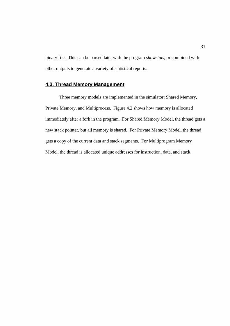
4.3. Thread Memory Management
Three memory models are implemented in the simulator: Shared Memory,
Private Memory, and Multiprocess. Figure 4.2 shows how memory is allocated
immediately after a fork in the program. For Shared Memory Model, the thread gets a
new stack pointer, but all memory is shared. For Private Memory Model, the thread
gets a copy of the current data and stack segments. For Multiprogram Memory
Model, the thread is allocated unique addresses for instruction, data, and stack.

32
I
Data
Stack
Stack
I
Data
Stack
Data(copy)
Stack(Copy)
I
Data
Stack
I
Data
Stack
Shared Private Mul t iprogramA
ddre
ss
thread 0 thread 0 thread 0thread 1 thread 1 thread 1
Figure 4.2. Memory Block diagrams immediately after a fork in each memory model.
I = program instruction memory, Data = static data and heap,
Stack = program stack (temporary variables, procedure calls, etc.).
4.3.1. Shared Memory Model
The Shared Memory Model is the one which was described in the Architecture
chapter, and is the default model. A new thread gets a unique stack pointer, but
shares all memory with the other threads. Instructions begin fetching from the very
next address for both threads.
Care must be taken when writing benchmarks for this model, that no thread
interferes with the other threads use of memory. Global variables may be read freely,

33
but writes should be controlled by locks or in atomic blocks to prevent data
corruption. Stack data may not be used across a fork because the child will not see
the same stack pointer as the parent. One way of avoiding this is to do a procedure
call immediately after the fork, and declare all local variables there. Each thread will
place its local variables in a different stack. Another way is to use the interprocess
communication registers, which all threads have shared access to.
One more problem is that some of the standard C library routines are not
reentrant capable. Routines like malloc and printf have been seen to break when
called by two Shared Memory threads at the same time. Either avoid these calls in a
threaded section, or make them atomic with the m_exclusive_run() instruction.
4.3.2. Private (Non-Shared) Memory Model
The Private Memory Model was implemented to make the porting of
benchmarks easier. Some benchmarks were not written with shared-memory
multithreading in mind, and have large amounts of read/write global data structures.
To port these to the Shared Memory Model would require rewriting each of these data
structures. A good compiler could handle this, but one is not currently available for
this architecture. To keep from having to extensively rewrite benchmarks, each
thread gets a copy of the data and stack memories. Each thread can continue using
the memory as if it were private, and program operation is unaffected.
When data synchronization is required, the new instructions
m_set_shared() and m_get_shared() can copy a block of data from one

34
thread to another. This is used in the benchmarks to write their results to thread 0
before terminating. In this model only, thread 0 is always the thread to continue after
a join. If it reaches the join before other threads, it goes to sleep until all others have
terminated. This simplifies the explicit sharing of data, as well as speeding
simulation as discussed below in the section titled simulator internals.
The drawback to this is that realism is sacrificed. Two diverging copies of
data memory are aliased onto the same memory addresses. The Data Cache model
treats these as identical for determining cache hits or misses, so one can expect higher
hit rates than normal.
A hardware implementation of this would be difficult at best. A DMA engine
would be required. To prevent having to copy the entire Data and Stack spaces before
starting the child process, a map could be maintained, much like a dirty cache
indication, and only duplicate memory when a write occurs. This would be expensive
to implement, and is not proposed as a proper solution. Instead, treat this model as an
approximation to the Shared Memory Model. Only the occasional write to this
memory would result in an additional cache miss. The additional benchmarks this
makes available to us, makes up for the small loss in accuracy.
4.3.3. Multiprogram Memory Model
The Multiprogram Memory Model allows independent programs to be run as
if they were threads. They are all mapped into memory space, but since each has its
own address range, no conflicts occur. This model is expected to have higher

35
Instruction Cache miss rates, since there is no code sharing going on. Also these
independent programs may have addresses that alias to the same block in the cache
further increasing the miss rate.
This is implemented in the simulator as multiple trace reads. Each benchmark
program is run separately and creates a long instruction trace file. The multithreaded
simulator can then read multiple tracefiles as threads, remapping the address as each
instruction is read.
The multiprogram model could be implemented in a real processor simply by
having Operating System support that can handle the process threads.
This model may also be an approximation of programs that have multiple
threads doing completely different functions like user interface, file I/O, and data
processing all in parallel. They would look much the same as this model, with
different threads accessing different instruction routines and different data, while still
being in one program. Since none of my explicitly threaded benchmarks use this
popular variety of threading, the multiprogram model is a good approximation and
adds to the diversity of benchmark architectures to study.
4.4. Atomic transactions
atom: an indivisible particle. -–Webster’s
Dictionary

36
As in all parallel processing environments, some activities need to be handled
atomically, such that no other thread's activities could interfere or change a value in
the middle of another's critical section of code. In a multithreaded microprocessor,
this is quite easy to do. The instruction m_exclusive_run() temporarily locks
one thread into exclusive execution. When the transaction is complete, it is called
again to unlock the thread. This locking can be arbitrarily nested, such that procedure
calls which have locked sections can be called within locked sections of code, and the
thread is only unlocked when the number of unlocks equals the number of locks. If a
join is encountered, any exclusive_run lock is broken to prevent processor
deadlock.
This locking mechanism can allow the unmodified use of non-reentrant library
calls within Shared Memory simulations by placing a lock before and an unlock after.
This can also be used to track down a section of code that is causing cross-thread
interference, by selectively placing locks and unlocks and running the program to see
when the problem disappears. It can usually be narrowed down to a single line of
offending code.
There is a slight performance penalty associated with an exclusive_run
section of code. Any time that an exclusive instruction is anywhere in the Instruction
Window, the normally loose rules for loads and stores from different threads being
allowed to issue out of order are tightened to prevent something from interfering with
the atomic transaction. This tightening of the rules also applies if a fork or join
instruction is in the window, as these are also synchronization commands.

37
4.5. Simulator internals
With the Shared Memory Model, all threads execute in the same Unix
process. This runs quite fast and efficiently. All memory conflict resolution is
handled by the benchmark program, instead of the simulator, and is thus the more
difficult model to program for.
For the second model with Private Memory, the simulator forks off a separate
child process for each thread, shown in Figure 4.3. This allows the benchmark to
execute without much fear of side effects due to other threads. There is a penalty for
this, and that is speed. The act of forking under Unix is a relatively big event,
duplicating the context of the process. In addition to this overhead as each thread
starts is that now all process communication must be explicit. With threads executing
in separate processes from the superscalar model of the processor, every instruction
must be passed through this communication channel. Note that thread 0 is always
executed by the same process as the superscalar simulator. This eliminates the
communication overhead for one of the threads and speeds simulation.

38
SuperscalarModel
ScalarPreprocess
Thread n
ScalarPreprocess
Thread 3
ScalarPreprocess
Thread 2
ScalarPreprocess
Thread 1
ScalarPreprocess
Thread 0
Command Pipe
Instruct ion Stream Pipe
Command Pipe
Instruct ion Stream Pipe
Command Pipe
Instruct ion Stream Pipe
Command Pipe
Instruct ion Stream Pipe
Figure 4.3. Communication between simulator processes in the Private Memorymode.
Bold Rectangles indicate separate Unix processes and arrows indicate pipes.
The separate processes communicate through pipes. Each thread gets two
pipes exclusively allocated to it. One feeds a stream of instructions from the scalar
execution portion to the superscalar process. Another pipe called the command pipe
sends information to the threads when needed such as:
• Acknowledgment of receiving instructions. This lets the thread know at what
point the superscalar unit is consuming its instruction stream. If the thread was
allowed to generate instructions at its own speed, it would quickly create a very
large buffer of executed instructions, and either crash or run very slowly. Once it

39
knows how far the supervisor is ahead, it will only execute a few instructions
before checking where the supervisor process is at. The process will suspend
itself automatically if the supervisor has not sent any messages back on the
command channel, keeping the thread from getting too far ahead.
• IPC register value when thread executes an ipc_read command. This allows the
value to be loaded into the scalar unit's register so it can be acted upon.
• Fork authorization. When a thread executes a fork command, it needs to assign a
thread id to the new child process. Since each thread does not know what other
threads are active, it can only get this information from the superscalar process.
• Join termination. When a join command executes, it needs to determine whether
or not to proceed. The superscalar process sequences the different thread's
instructions, and then can correctly assign which threads are to be terminated or
continue.
• Shared memory data. Similar to an IPC value, but can send an arbitrary sized
block of data, along with a destination address. This allows child processes to
store their results in the parent's memory space without its intervention, or to read
a block of data from the parent.
For the third memory model, Multiprogram, each program is pre-executed by
a separate simulation, which generates a tracefile. The Multiprogram simulator reads
each of these trace files in from a file. If the file has a .gz extension, a pipe is created
through the gunzip program to decompress the stream on-the-fly. This has about a

40
10% speed penalty for the simulation, but results in much lower storage requirements.
Each instruction read from the stream is remapped into its own address space by
adding a constant offset per thread. Any addresses used by the instructions such as
loads, stores, and control transfers are also modified. From there, the instructions are
passed into the Shared Memory Model of the simulator and processed normally.
4.6. Simulator limitations and potential improvements
No simulator is perfect in its ability to represent real operating conditions.
This simulator is very accurate in many ways, but does have its share of limitations.
The following list describes all of the ones I have become aware of.
• The compiler does not understand threading instructions, and treats them as
procedure calls. This typically results in these instructions being expanded into 2
to 3 real instructions, as it expects to pass the parameters in particular registers.
The actual threading instruction is later translated from a trap call into the
instruction opcode with source registers matching the procedure call standard
variable passing registers. This additional overhead appears to be trivial
compared to the real multithread overhead of loop initialization.
• No easy mechanism is present to support stack variables across forks. This makes
writing benchmarks difficult, and increases the amount of loop initialization
overhead in the multithreaded code.
• No Level 2 Cache model is implemented.

41
• The store queue in the Load/Store Unit is not modeled in detail, but is assumed to
always have an available entry for new stores when they are requested.
• The Operating System is not simulated. The simulator traps Operating System
calls and makes those requests to the Operating System it is running under. The
Operating System would be very good to simulate because of the inherent
threaded nature of its tasks, but because of the size of the sourcecode, it is not
feasible to simulate at the level of detail which this simulator runs.
• Faster simulation would enable longer benchmark runs. I had to make the
tradeoff of long simulation runs verses diversity of parameter variations. I chose
shorter runs (8-35 million instructions) with more variety of parameters. These
shorter runs do not fully reflect the cache effects.

42
5. BENCHMARKS
5.1. The Multimedia Desktop Environment
Previous studies of multithreading have focused on high performance
scientific or server applications. I show in these simulations that the multimedia
desktop has much to gain from the same techniques. Significant data parallelism,
real-time latency intolerance, and interfacing to low bandwidth I/O devices all fit the
multithreaded model’s best aspects.
Most of the tasks to be performed on a multimedia desktop machine are easily
adaptable to multithreaded operation, and many already are, because of the inherent
parallelism in them. Also, since multimedia implies more than one type of media at a
time, many of these will be running concurrently. Lack of performance may readily
be seen by the user as long latencies or poor quality and detracts from the system’s
usefulness. Table 5.1 shows how the selection of benchmarks are representative of
many of these categories of tasks, giving insight into whether they provide an
appropriate mix of instructions for a multithreaded microprocessor.

43
Table 5.1. Some typical desktop tasks in a multimedia desktop environment.
Items in bold are represented by benchmarks in this thesis.
Media Example uses BenchmarksVideo play movies, video conferencing, movie
authoring, 3D games, gesture recognitionmpegd, mpeg2e
StillImages
image filtering, compression, scenerendering, object recognition
nlfilt, cjpeg, pov,xmountains
Audio compression, filtering, speech synthesis,voice recognition, music synthesis
sox, say
Text OCR, handwriting recognition, spellcheck,translation, searching
diff
I/O file compression, virus scanning, Internet,printer preprocessing, home automation
gzip
AI artificial intelligence, remote agents
5.2. Programming environment
The benchmarks used were written in C and available freely as UNIX source
code. The programs were compiled using the SDSP version of the gnu C compiler.
The -O2 optimization command was usually used. Threads are added by including
m_fork_n() procedure calls in the C source code. These are left as unresolved
links by the compiler and linker, and are interpreted by the simulator as extensions of
the processor instruction set.
Not wanting to completely re-write the benchmarks, I looked for easy ways to
add multithreading. The main data processing loops in the program have been
divided into multiple threads. In this way, concurrency is increased without too much
overhead of initiating threads.

44
For some applications, the processing is done in nested loops. This leads to
the dilemma of where to place the threading. With an inner loop, more forking and
joining adds more overhead. With a long outer loop, any unbalance in the workload
can result in a significant period of time where a limited number of threads finish the
remaining iteration after the others have completed. In general, coarse grained
threading was preferred, but in mpeg2e, a relatively fine grained threading was used.
See Appendix A for details on how the benchmarks were threaded.
5.3. Discussion of the individual benchmarks and datasets
This chapter describes the benchmarks used. First, the benchmarks are
described with their data sets. Then, statistics are shown for each benchmark with a
default hardware configuration.
5.3.1. Workload and datasets
Name Data in Data out Instruction Countmpeg2e 3 image frames 320x280 3 frame MPEG2 movie 35,918,652
Mpeg2e is a video compression program. It reads a set of images, and creates
an mpeg2 video stream consisting of I, B, and P type frames. This dataset has one of
each type frame and comes from the popular ping-pong sequence, but scaled down to
provide smaller images more suitable to simulation, as well as more appropriate for
video conferencing applications which demand real-time performance. All other
parameters were set to their defaults provided with the sourcecode [MPE94].

45
Name Data in Data out Instruction Countnlfilt 100x100 image 100x100 image 19,192,033
Nlfilt is a non-linear image filter. The edge enhance module simulated here is
typical of image processing. Only the image processing routine was included, file
I/O was not. This was chosen because the typical interactive image editing
application loads an image once, then performs a series of filters interacting with the
user in real time. Real time performance is the key factor in user interaction. The
sourcecode was taken from the netpbm library [NET93] routine called pnmnlfilt
[PNM93]. The code was modified by replacing all library references with local
routines that use a simple binary file format, trading flexibility for simulation speed.
Name Data in Data out Instruction Countpov simple.pov scene desc. 25x25 pixel image 7,962,116
Pov is the Persistence of Vision ray tracer [POV96]. It creates an image by
tracking rays of light as they bounce around a scene full of geometrically defined
objects. This may be used to view a proposed architectural design, or fantasy world
in fine detail. It is not typically run in real time, as there are less precise methods
available for quick previews or real-time games.

46
Name Data in Data out Instruction Countisuite N/A N/A 8,000,000 gzip Text file compressed file 2,000,000 mpegd 3 frame MPEG1 movie 3 individual frames 2,000,000 diff Two text files list of lines that differ 2,000,000 cjpeg gif image jpeg image 2,000,000
Isuite consists of four integer programs run in parallel. Each program was cut
off at 2,000,000 instructions to balance the load. Gzip compresses data files to
conserve storage or network bandwidth [GZI93, LZ77]. Mpegd decompresses a video
stream in real time for immediate display of movies, game animation, or downloaded
entertainment content [PVR93]. Diff is a typical text filter representative of a whole
class of applications that consist primarily of file I/O with limited computation
[DIF93]. Cjpeg compresses images for storage and transmission. It is also used in
very low power processors with low clock rates in digital cameras where speed and
efficiency are very important [JPG96, WAL91].
Name Data in Data out Instruction Countfsuite N/A N/A 8,000,000 xmountains seed number image of fractal terrain 2,000,000 whet iterations N/A 2,000,000 say text phrase audio speech file 2,000,000 sox audio file filtered audio file 2,000,000
Fsuite consists of four floating point programs run in parallel. Each program
was cut off at 2,000,000 instructions to balance the load. Xmountains generates a 3D
view of terrain based on the infinite resolution of fractals, as would be used in a flight
simulator or similar program [XMO95]. Whet is a benchmark application that is very

47
heavy in floating point operations. Its only purpose is to stress the floating point
capabilities of a processor [WHE87, CUR76]. Say can convert text into speech, and
can be used to provide a more natural interface to the computer [SAY94, HOL64,
KLA80]. Sox manipulates an audio waveform, in this case just upsampling it, but
with the right algorithms, it could as well provide multichannel surround sound
separation, or audio special effects [SOX94, SMI93].
5.3.2. Profile
The benchmarks were all profiled to determine what routines formed the core
loops, and which contained the most processing. These were selected for re-coding
with threads. The profiles that can be found in Appendix A include information
about how much additional overhead is in the 4 thread run of the program versus the
single thread run.
5.3.3. Properties
Table 3 shows properties of the benchmarks. The figures represent the single
thread version under default conditions, except for the last four items which are for a
4 thread run. Tables 4 and 5 later on will break down isuite and fsuite into their
component parts. See Appendix 3 for detailed description and equations for each
item.

48
Table 5.2. Properties of the benchmarks.
label: mpeg2e nlfilt pov isuite fsuitememory model: Shared Shared Private Multiprogram Multiprogramcycles: 10,685,764 2,795,696 4,676,530 1,392,791 4,573,652float work: 0.269 0.014 1.519 0.000 1.504instructions: 35,918,652 19,192,033 7,962,116 8,000,000 8,000,000quick_instr: 257,583 1,059,949 1,436,048 0 0CPI: 0.297 0.146 0.587 0.174 0.572IPC: 3.361 6.865 1.703 5.744 1.749avg fetch: 6.748 7.691 5.675 6.495 6.336avg issue: 3.182 6.808 1.345 5.257 1.454total delays: 57.377% 11.840% 74.165% 14.291% 74.916% su stalls: 36.188% 7.901% 62.936% 7.113% 68.230% br delays: 20.970% 3.850% 11.036% 6.348% 6.291% i delays: 0.219% 0.089% 0.193% 0.831% 0.396%i swap: 58.342% 0.000% 40.819% 24.567% 44.128%d swap: 44.818% 41.056% 0.000% 92.738% 5.201%i miss: 0.088% 0.020% 0.129% 0.187% 0.286%d miss: 0.035% 0.082% 0.035% 2.607% 0.079%fetch deficit: 15.722% 3.886% 29.158% 18.959% 21.029%pred rate: 35.081% 66.986% 73.591% 93.896% 66.283%br penalty: 2.851 3.441 2.349 2.079 2.324commit bypass: 0.112% 0.013% 1.456% 1.177% 0.694%fetch cycles: 6,818,806 2,574,800 1,733,330 1,293,718 1,453,051
code growth: 0.421% 0.005% 0.045% 0.000% 0.000%%threaded: 34.459% 99.076% 92.171% 95.180% 81.447%total threads: 1405 4 73 4 4speedup 19.433% 2.891% 14.843% 8.817% 16.019%
The item float work is a weighted sum of floating point operations, with the
weight being the number of cycles it takes to complete that type of operation, then
normalized to the total number of instructions in the benchmark. Thus, pov and fsuite
are very heavy users of floating point, while mpeg2e and nlfilt use less, and isuite uses
none.

49
The average fetch entry shows that our default mechanism of dual fetch does a
pretty good job of retrieving 5.6 to 7.6 instructions. This forms the upper limit on
throughput.
The cycles per instruction (CPI) or its inverse (IPC) varies considerably across
the benchmarks. The floating point apps have much lower rates of instruction
throughput than the integer ones, which indicates the floating point operations are a
significant source of the stalls in the Scheduling Unit. Looking down at the total
delays, and the next three items after it, which break down the cause of delays, one
can see the dominance of Scheduling Unit stalls in those floating point applications.
Branch delays are also a considerable portion of the delay, which indicates
that the default mechanism of two bit history branch prediction isn’t always a good
performer. The pred rate entry for mpeg2e shows that its prediction rate is only 35%.
The br penalty line shows that for each of those mispredicted branches, an average of
2 to 3.5 fetch cycles are wasted.
The commit bypass item show what percentage of stalls were avoided by
being able to commit from slots farther up the Instruction Window, and is less than
1.5% for all benchmarks. For these single threaded applications, the only situation
this is ever used is to eat the pipe bubbles on completely invalidated blocks after a
bad branch prediction has been detected.
Instruction and Data Cache miss rates are very low, well under 1% in all but
the isuite Data Cache. This translates into less than 1% delays for all instruction fetch
delays. The significance of the swap items is described later in the next chapter.

50
Up to now, all the items in the table have been describing the single thread
benchmarks. The last 4 lines describe what happens when 4 threads are used. The
code grows for all but the suites, but less than half of one percent for the worst case.
The suites don’t have code growth, because the programs don’t change, as it is only
interleaving the different programs.
The %threaded entry shows that for nlfilt, pov, and isuite, greater than 90% of
the cycles have more than one thread available, while fsuite has 81%, and mpeg2e
only has 34%. The suites are only less than 100% because of load imbalance, some
components have a higher IPC than others and complete early. For the threaded
applications, the percentage reflects how much of the program is essentially scalar,
and cannot be easily threaded.
The total threads line shows that most benchmarks were threaded very coarse
grained. Mpeg2e has the highest number of threads, but also had the highest amount
of code growth, showing the cost involved in fine grained threading.
The last item is the most important. This shows the amount of speedup
between the scalar version and the 4 thread version. For nlfilt, it is very low, about
2.9%. This application already has the highest IPC. For the other integer application,
isuite, it also was low at 8.8%. The floating point applications did better, 14.8% to
19.4%. The speedup numbers are nowhere near the many times speedup that others
have reported when simulating scientific applications designed for parallel machines,
but for the small amount of extra cost involved in adding multithreading to a
superscalar processor, they are quite good.

51
Table 5.3 shows the benchmarks that make up the isuite benchmark and their
properties.
Table 5.3. Integer Suite breakdown.
label: gzip mpegd diff cjpeg isuitecycles: 625,530 412,310 583,134 408,932 1,392,791float work: 0.000 0.000 0.000 0.000 0.000instructions: 2,000,000 2,000,000 2,000,000 2,000,000 8,000,000quick_instr: 0 0 0 0 0CPI: 0.313 0.206 0.292 0.204 0.174IPC: 3.197 4.851 3.430 4.891 5.744avg fetch: 4.828 5.152 3.907 5.451 6.495avg issue: 3.081 4.396 2.976 4.674 5.257total delays: 33.928% 6.524% 14.868% 14.940% 14.291%su stalls: 2.177% 3.576% 9.270% 2.071% 7.113%br delays: 31.408% 2.344% 5.342% 11.306% 6.348%i delays: 0.342% 0.603% 0.256% 1.563% 0.831%i swap: 0.000% 0.604% 0.000% 26.625% 24.567%d swap: 55.488% 79.334% 94.032% 52.303% 92.738%i miss: 0.103% 0.128% 0.058% 0.347% 0.187%d miss: 2.221% 2.489% 5.565% 0.479% 2.607%fetch deficit: 39.706% 35.684% 51.186% 32.102% 18.959%pred rate: 51.422% 98.207% 94.389% 76.860% 93.896%br penalty: 2.914 2.857 1.983 2.236 2.079commit bypass: 0.095% 0.399% 0.044% 0.236% 1.177%fetch cycles: 611,901 397,564 529,079 400,461 1,293,718
code growth: 0.000% 0.000% 0.000% 0.000% 0.000%%threaded: 0.000% 0.000% 0.000% 0.000% 95.180%total threads: 1 1 1 1 4speedup: N/A N/A N/A N/A 8.817%
In the integer suite, gzip has the lowest throughput (IPC), and thus is the cause
of only having isuite 95% threaded, due to load imbalance between the different
programs within the suite. The low throughput on gzip is primarily due to poor
branch prediction. Cjpeg, another compression routine also has poor branch

52
prediction. On the other end of the spectrum, the decompression routine mpegd has
over 98% prediction accuracy
The text comparison program, diff, has the highest Data Cache miss rate, more
than double any of the other benchmarks at 5.5%.
Table 5.4 shows the benchmarks that make up the fsuite benchmark and their
properties.
The floating point application suite has a low %threaded amount at 81%, due
to the xmountain’s low throughput, making the load imbalanced. The reason for that
is it has a very high float work rating, more than double the other applications. It also
has the lowest avg fetch.
Despite the imbalance, the combined suite has 16% speedup, which is high
because the floating point latencies can be hidden by multithreading.

53
Table 5.4. Floating point suite breakdown.
label: xmountains whet say sox fsuitecycles: 1,783,308 862,390 736,496 840,616 4,573,652float work: 3.213 1.210 0.656 0.936 1.504instructions: 2,000,000 2,000,000 2,000,000 2,000,000 8,000,000quick_instr: 0 0 0 0 0CPI: 0.892 0.431 0.368 0.420 0.572IPC: 1.122 2.319 2.716 2.379 1.749avg fetch: 4.144 5.199 5.900 5.869 6.336avg issue: 0.759 2.009 2.413 2.121 1.454total delays: 75.990% 56.812% 56.364% 62.068% 74.916%su stalls: 68.144% 51.959% 47.930% 55.328% 68.230%br delays: 7.592% 4.472% 7.275% 6.396% 6.291%i delays: 0.254% 0.381% 1.158% 0.344% 0.396%i swap: 6.858% 1.065% 40.880% 2.422% 44.128%d swap: 3.936% 0.000% 4.786% 0.699% 5.201%i miss: 0.187% 0.170% 0.500% 0.169% 0.286%d miss: 0.176% 0.016% 0.144% 0.030% 0.079%fetch deficit: 48.301% 35.123% 26.624% 26.756% 21.029%pred rate: 66.840% 78.021% 54.232% 65.724% 66.283%br penalty: 2.288 2.343 2.417 2.395 2.324commit bypass: 2.193% 0.012% 0.024% 0.007% 0.694%fetch cycles: 568,089 414,301 383,482 375,520 1,453,051
code growth: 0.000% 0.000% 0.000% 0.000% 0.000%%threaded: 0.000% 0.000% 0.000% 0.000% 81.447%total threads: 1 1 1 1 4speedup N/A N/A N/A N/A 16.019%

54
6. RESOURCE ANALYSIS RESULTS
6.1. Default parameters
In a system that’s nearly infinitely configurable, choosing where to start is
difficult but critical to finding the best solution and most interesting interactions. The
configuration developed by Wallace [WAL93a] was the starting point, but it was
necessary to scale some of the resources up to take full advantage of the increased
parallelism available to the multithreaded benchmarks. Hundreds of preliminary
simulations were run that are not documented here, in order to see where the
interesting bends in the graphs occur, while not having any one resource low enough
that its limits mask other effects. Using that, a set of parameters was selected as a
starting point for the rest of the runs. These are summarized in Table 6.1, along with
the limits imposed by the architecture or simulator.
From the default resource configuration, one parameter is varied at a time (or
occasionally related parameters are changed as a set) to see how performance is
affected. This gives insight to the resource requirements and dependencies in the
benchmarks.

55
Table 6.1. Default Resource Configuration.
PARAMETER AVAILABLE RANGE DEFAULTfetch block size 1-16 instructions 8 instructionsdepth of RBIW 1-15 blocks 4 blockscompletion slots 1-15 blocks 2 blocksnumber of threads 1-7 4thread scheduling X,R/L/C,I,B,P,F LIBPFmaximum issue/result ports 1-16 16functional units: ALU 1-16 8functional units: FPU 1-16 4functional units: Multiply 1-16 4functional units: Load/Store 1-16 2result bypassing off / on onI Cache 0-512 KB 64 KBD Cache 0-512 KB 64 KBCache Associativity 1-8 way 4 waycache latency/interval 1+ / 1+ 5 / 3cache line size 1+ fetch blocks 1 fetch block (32 bytes)prefetch off / dual / ideal dualbranch prediction algorithm 2 bit / always not taken / perfect 2 bitbranch prediction table size 0-256 entry shared / each 256 entry sharedmisprediction bubbles 0+ 1thread stack size any $8200 bytes (32.5 KB)
Figure 6.1 shows Cycles Per Instruction (CPI) as the number of threads is
varied for each benchmark. Note that some of the benchmarks do not have all the
threads graphed. For the suites, only 1, 2, and 4 threads were run, since the suites
each have 4 programs in them. If an odd number were run, it would not be an
accurate result because of the load imbalance. The final column, average, is an
average of all the benchmarks. Sometimes Instructions Per Cycle (IPC) feels more
intuitive than CPI. For those, the data is inverted in Figure 6.2 to show IPC. The rest
of the thesis will stick to CPI for consistency [EMM97].

56
Threads
0.0
0.1
0.2
0.3
0.4
0.5
0.6
mpeg2e nlfilt pov isuite fsuite average
Benchmark
CP
I
1 2 3 4 5 6 7
Figure 6.1. CPI versus threads.
Threads
0
1
2
3
4
5
6
7
8
mpeg2e nlfilt pov isuite fsuite average
Benchmark
IPC
1 2 3 4 5 6 7
Figure 6.2. IPC versus threads.

57
Nlfilt has the most inherent parallelism, approaching the 8 instructions per
cycle fetch limit, and thus the least to gain from multithreading. Pov and fsuite have
the worst performance, and most to gain from the additional parallelism. These two
use of floating point extensively.
Figure 6.3 shows this same data represented as speedup, which is the relative
execution time of the multithreaded benchmark versus the single threaded.
Threads
0%
2%
4%
6%
8%
10%
12%
14%
16%
18%
20%
mpeg2e nlfilt pov isuite fsuite average
Benchmark
Sp
eed
up
1 2 3 4 5 6 7
Figure 6.3. Speedup versus Threads
The first few threads provide significant speedup, but after 4 or 5 threads, the
additional overhead begins to outweigh the diminishing gains from more parallelism.
These trends have discontinuities in them due to the load imbalance with certain
numbers of threads that are not multiples of the loop sizes. This can be seen in

58
mpeg2e and nlfilt, which have better performance on 6 threads than they do on 5. For
nlfilt, 3 threads is the best. For pov, 5 threads is best. For the suites and mpeg2e, 4
threads is best.
For all the remaining threaded runs in this thesis, 4 threads were used. This
was chosen to be the same for all benchmarks for consistency. Among all
benchmarks, 4 threads is close to the greatest speedup.
6.2. Fetch limits
Instruction fetching is the first bottleneck in the processor pipeline. If
instructions cannot be fetched in enough quantity, the processor will spend much of
its time idle. Several parameters control the flow of instructions into the processor.
The following sections look at fetch block size, fetch alignment through self-aligned
fetching or prefetching, branch prediction, and Instruction Cache.
6.2.1. Fetch Block Size
In Figure 6.4, the size of the fetch block is varied while the total size of the
Instruction Window is kept at 32 entries.

59
Fetchblock / RBIW Depth
0.0
0.1
0.2
0.3
0.4
0.5
0.6
0.7
0.8
1m
peg2
e
4m
peg2
e
1 nlfil
t
4 nlfil
t
1 pov
4 pov
1is
uite
4is
uite
1fs
uite
4fs
uite
1av
erag
e
4av
erag
e
Threads / Benchmark
CP
I
4 / 8 8 / 4 16 / 2
Figure 6.4. Block Size, keeping Instruction Window to 32 entries.
The default configuration of 8/4 is the best for all the multithreaded cases.
The larger fetch block 16 is just slightly better in the highest throughput single
threaded cases. These must have very little data dependence, or the pipe would stall
frequently with only two cycles between fetch and retire.
6.2.2. Fetch Alignment: Prefetching
Figure 6.5 compares fetching models. No prefetch means that a single cache
line is fetched each cycle. Dual fetch refers to fetching two cache lines every cycle,
then re-aligning the instructions to begin at the start of the block. This is also called
self-aligned fetch block. Perfect fetch refers to a theoretical prefetch scheme that

60
always returns a full block of instructions, even when the block is misaligned or
correctly predicted branches occur within the block.
Prefetch
0.0
0.1
0.2
0.3
0.4
0.5
0.6
0.7
0.8
1m
peg2
e
4m
peg2
e
1 nlfil
t
4 nlfil
t
1 pov
4 pov
1is
uite
4is
uite
1fs
uite
4fs
uite
1av
erag
e
4av
erag
e
Threads / Benchmark
CP
I
no prefetch dual fetch perfectfetch
Figure 6.5. Prefetching
Dual fetch is approximately 6-7% slower than perfect fetch. Considering the
additional cost of prefetching and fact that it would most likely increase the pipeline
length, then dual fetch is a good compromise.
The no prefetch configuration of single threaded pov has much worse (+29%)
performance than the dual fetch configuration. The multithreaded pov only has +11%
difference, indicating that the threading can compensate for some of the poor fetch
performance. In all the other applications, no significant difference exists between

61
the benefits gained by improved fetch schemes for single and multithreaded
applications.
Nlfilt gets no performance increase with any of the fetch improvements,
indicating that its performance is not limited by fetch.
6.2.3. Branch Prediction
The branch prediction mechanism is responsible for reducing the amount of
garbage instructions fetched by the processor. In Figure 6.6, the bsimple model
always predicts not taken. 64 and 255 are the number of entries in the branch target
buffer, a two bit counter mechanism for determining if a branch should be taken or
not. 256 each refers to separate branch target buffers for each thread. Perfect
predictor is never wrong, and shows the possible performance limits to the branch
prediction.

62
Branch Configuration
0.0
0.1
0.2
0.3
0.4
0.5
0.6
0.7
0.8
1m
peg2
e
4m
peg2
e
1nl
filt
4nl
filt
1 pov
4 pov
1is
uite
4is
uite
1fs
uite
4fs
uite
1av
erag
e
4av
erag
e
Threads / Benchmark
CP
I
bsimple 64 256 256 each perfect pred
Figure 6.6. Branch Prediction
It is obvious from this graph that branch prediction is a much smaller share of
performance with multithreaded programs than single thread programs. Expensive
dynamic prediction is important in the single thread models, but of little benefit when
multiple threads are available. Also shown is that inter-thread interference can often
reduce the effectiveness of the two bit branch predictor, such that the simple not-
taken prediction performs better in both mpeg2e and nlfilt, and is about the same in
the others.
For the multithreaded case, all models achieve nearly the same results as the
perfect prediction because there is time to resolve the branch while other threads are
executing. Bsimple actually outperforms any of the other real cases because it never

63
discards the instructions within the fetch block after the branch instruction until the
branch has been resolved, while the other models will mistakenly discard these on a
false taken branch prediction.
6.2.4. Instruction Cache
In Figure 6.7, the Instruction Cache is varied from 16K to 256K with both a
direct mapped (1-way) and an associative (4-way) arrangement. Perfect refers to a
cache that never misses, giving a best case reference point.
Instruction Cache
0.0
0.1
0.2
0.3
0.4
0.5
0.6
0.7
0.8
1m
peg2
e
4m
peg2
e
1nl
filt
4nl
filt
1 pov
4 pov
1is
uite
4is
uite
1fs
uite
4fs
uite
1av
erag
e
4av
erag
e
Threads / Benchmark
CP
I
16K (1 way) 64K (1 way) 256K (1 way) 16K (4 way) 64K (4 way) 256K (4 way) Perfect
Figure 6.7. Instruction Cache

64
For all but pov with a small cache, the associative cache does not gain us
much, and in threaded fsuite and nlfilt, a small associative cache can perform worse
than direct mapped.
It is possible that these benchmarks are not run long enough to show all of the
cache effects. To test for this, Figure 6.8 shows the percentage of instruction misses
that replace data in the cache (as opposed to hitting an empty cache entry). An
indication that this is a poor model of steady state performance is if the graph is not
near 100%. The graph shows that most benchmarks only approach 100% for the
smallest cache, and some like nlfilt and isuite never get very high at all. This
indicates that much longer simulations are needed to accurately model cache effects.
The only exception to this is pov, which has swap rates over 90% for all of the
direct mapped cache models. Back in Figure 6.7, we can see that for pov, the
threaded version had slightly less dependence on cache size for the multithreaded
version than the single thread one. This is as can be expected, since the multithreaded
processor is not blocked from executing other threads when a cache miss occurs.
From this benchmark, we can also see that the associative cache performs better than
the direct mapped, as less contention is seen.

65
Instruction Cache Usage
0%
10%
20%
30%
40%
50%
60%
70%
80%
90%
100%
1m
peg2
e
4m
peg2
e
1nl
filt
4nl
filt
1 pov
4 pov
1is
uite
4is
uite
1fs
uite
4fs
uite
1av
erag
e
4av
erag
e
Threads / Benchmark
% in
stru
ctio
n c
ach
e sw
ap
16K (1 way) 64K (1 way) 256K (1 way) 16K (4 way) 64K (4 way) 256K (4 way) Perfect
Figure 6.8. Instruction Cache Usage.
Some very good papers have been written on cache models for multithreaded
applications [JOU90, MCF91, BLU92, LEE95, FAR97, LO98, PHI96], and our
results here, though seriously limited by the under-utilization of the cache, agree with
them that spatial locality is reduced while threads can compensate for the additional
misses. For real cache model analysis, a much simpler processor model is usually
used to handle many times the size of instruction runs we can use here.
Figure 6.9 shows a comparison of blocking versus nonblocking Instruction
Cache. The differences are too small to see.

66
Blocking / Nonblocking ICache
0.0
0.1
0.2
0.3
0.4
0.5
0.6
1m
peg2
e
4m
peg2
e
1nl
filt
4nl
filt
1 pov
4 pov
1is
uite
4is
uite
1fs
uite
4fs
uite
1av
erag
e
4av
erag
e
Threads / Benchmark
CP
I
blocking nonblocking
Figure 6.9. Blocking vs Non-Blocking Instruction Cache.
6.3. Data and pipeline limits
Once the instructions are in the processor, there must be enough Execution
Units to process them all with minimal stalls. The Data Cache must be able to
provide the required memory accesses in a timely manner. Finally, the Instruction
Window must be large enough that instructions have a chance to execute before
causing a stall
6.3.1. Functional Units: ALU, FPU, Load/Store
Figure 6.10 compares CPI while varying the number of Integer Execution
Units (ALU).

67
Integer ALU
0.0
0.1
0.2
0.3
0.4
0.5
0.6
1m
peg2
e
4m
peg2
e
1 nlfil
t
4 nlfil
t
1 pov
4 pov
1is
uite
4is
uite
1fs
uite
4fs
uite
1av
erag
e
4av
erag
e
Threads / Benchmark
CP
I
4 8 12
Figure 6.10. Integer ALU
For the floating point applications, 4 ALU’s are enough to reach maximum
performance, for the integer heavy applications, 8 ALU’s provide additional speedup.
In mpeg2e, the additional performance gained by going from 1 to 4 threads has
increased the reliance on ALU Units. While in the single thread version, only 2.3%
improvement is seen when going to 8 ALU’s, the threaded version shows 5.9%
improvement when adding those same additional ALU’s. This is due to the
additional resource utilization of the multithreaded version.
For all benchmarks, more than 8 integer ALU’s are entirely unused. This is
likely due to the maximum fetch bandwidth of 8 instructions per cycle becoming the
bottleneck.

68
Figure 6.11 varies the Floating Point Units (FPU).
Floating Point Units
0.0
0.2
0.4
0.6
0.8
1.0
1.2
1.4
1.6
1.8
1m
peg2
e
4m
peg2
e 1 nlfil
t
4 nlfil
t
1 pov
4 pov
1is
uite
4is
uite
1fs
uite
4fs
uite
1av
erag
e
4av
erag
e
Threads / Benchmark
CP
I
1 2 4 8 12
Figure 6.11. Floating Point Units.
Floating point intensive programs like pov and fsuite can make use of up to 8
or even 12 Floating Point Units. The first 4 are quite effective, beyond that, it is a
cost/performance tradeoff to determine if additional units are worthwhile.
The existence of threads does not appear to place an extra burden on FPU
resources.
Figure 6.12 varies the number of Load/Store Units. Each of which can
perform one load or one store each cycle.

69
Load / Store Units
0.0
0.1
0.2
0.3
0.4
0.5
0.6
0.7
1m
peg2
e
4m
peg2
e
1 nlfil
t
4 nlfil
t
1 pov
4 pov
1is
uite
4is
uite
1fs
uite
4fs
uite
1av
erag
e
4av
erag
e
Threads / Benchmark
CP
I
1 2 4 8
Figure 6.12. Load/Store Units.
The second Load/Store Unit is of significant performance importance. In
nlfilt, it cuts execution time nearly in half, taking CPI from 0.27 to 0.14 for either
single or multithreaded runs. In mpeg2e and isuite, the presence of a second
Load/Store Unit improves performance more for multithreaded versions than scalar.
More than 2 Load/Stores has little or no effect, probably due to the precedence
rules for executing loads before preceding stores within the same thread.
6.3.2. Data Cache
In Figure 6.13, the Data Cache is varied from 16K to 256K with both a direct
mapped (1-way) and an associative (4-way) arrangement. Perfect refers to a cache
that never misses, giving a best case reference point.

70
D Cache
0.0
0.1
0.2
0.3
0.4
0.5
0.6
1m
peg2
e
4m
peg2
e
1nl
filt
4nl
filt
1 pov
4 pov
1is
uite
4is
uite
1fs
uite
4fs
uite
1av
erag
e
4av
erag
e
Threads / Benchmarks
CP
I
16K (1 way) 64K (1 way) 256K (1 way) 16K (4 way) 64K (4 way) 256K (4 way) Perfect
Figure 6.13. Data Cache
Data Cache has very little impact on performance of these benchmarks. It is
quite likely that our data set size is too small to see much effect with the short
simulation runs done. To test for this, the following graph 6.14 shows percentage of
cache misses that cause a swap to occur (as opposed to filling an empty cache line). If
these are not near 100%, then the simulation has not reached the steady state
condition. This is the case for all but the smallest cache sizes.

71
Data Cache Usage
0%
10%
20%
30%
40%
50%
60%
70%
80%
90%
100%
1m
peg2
e
4m
peg2
e 1 nlfil
t
4 nlfil
t
1 pov
4 pov
1is
uite
4is
uite
1fs
uite
4fs
uite
1av
erag
e
4av
erag
e
Threads / Benchmark
% D
ata
Cac
he
Sw
ap
16K (1 way) 64K (1 way) 256K (1 way) 16K (4 way) 64K (4 way) 256K (4 way) Perfect
Figure 6.14. Data Cache Usage
Because the cache model is nearly useless with these small simulation runs, I
refer the reader back to the comments made about Instruction Cache in Section 6.2.4.
6.3.3. Instruction Window Depth
Figure 6.15 varies the depth of the Reorder Buffer / Instruction Window
(RBIW) which determines how long an instruction has to complete before stalling the
processor. Note that the default case has two Completion Slots, so one stalled thread
will not stall the entire processor, but two will.

72
RBIW Depth
0.0
0.1
0.2
0.3
0.4
0.5
0.6
0.7
0.8
1m
peg2
e
4m
peg2
e
1nl
filt
4nl
filt
1 pov
4 pov
1is
uite
4is
uite
1fs
uite
4fs
uite
1av
erag
e
4av
erag
e
Threads / Benchmark
CP
I
2 4 6 8
Figure 6.15. RBIW depth.
For the integer benchmarks isuite and nlfilt, a depth of more than 4 blocks is
nearly useless. For the floating point intensive applications however, 6 and 8 entries
will give better performance.
6.4. Thread parameters
There are some parameters that do not do much for a single threaded
processor, but can significantly impact performance with multiple threads. Being able
to bypass a stalled thread in the Instruction Window, and having a non-blocking
Instruction Cache are two such items. The thread scheduling algorithm can also have
an effect on the mix of instructions available.

73
6.4.1. Completion Slots
Figure 6.16 shows the result of being able to retire instructions from farther up
in the Instruction Window, if the entries below it are not from the same thread.
Completion Slots
0.0
0.1
0.2
0.3
0.4
0.5
0.6
0.7
1m
peg2
e
4m
peg2
e
1 nlfil
t
4 nlfil
t
1 pov
4 pov
1is
uite
4is
uite
1fs
uite
4fs
uite
1av
erag
e
4av
erag
eThreads / Benchmark
CP
I
1 2 3 4
Figure 6.16. Instruction Window Completion Slots.
There is a slight improvement in single thread performance, only because pipe
bubbles from blocks of instructions that were invalidated after a mispredicted branch
can be squashed with this mechanism. In multithreaded operation, we get
approximately 15% speedup from just one extra completion slot.
Performance of multithreaded applications can be even worse than their scalar
versions if completion bypassing is not allowed, as seen in fsuite. This is because the

74
high occurrences of floating point instructions are frequently stalling the pipeline.
The original code had the floating point operations grouped together, they are
benefiting from stall sharing as described in Chapter 2. However, when the multiple
threads are interleaved, these instructions are spread out, and do not benefit from this
stall sharing.
6.4.2. Thread Scheduling Algorithm
Figure 6.17 shows the results from changing the thread scheduling algorithm.
Thread Scheduling Algorithm (4 threads)
0
0.1
0.2
0.3
0.4
0.5
0.6
mpeg2e nlfilt pov isuite fsuite average
Benchmark
CP
I
L LI LB LP LF LIBPF RIBPF CIBPF XLIBPF
Figure 6.17. Scheduling Algorithm.
The scheduling algorithm is very customizable, and a variety of techniques
were tried here. The algorithm name comes from abbreviations for the various

75
options enabled. Normally, a new thread is chosen every fetch cycle, unless X is
specified to indicate coarse grained threading. With coarse grained threading, thread
switch only occurs when the current thread gets a low priority.
The order in which threads are checked can be one of three: R (Round Robin
order), L (Least Recently Used order), and C (Count order). Round Robin order
simply goes in thread number order 1, 2, 3, … Least Recently Used order modifies
this to account for the occasional fetch stalls in threads. If a thread loses its turn
because of an Instruction Cache miss, or other priority mechanism, this allows the
thread to get the next available slot when the priority changes, instead of having to
wait for all other threads to get another turn. The final ordering mechanism is Count
order, which looks at threads first which have the fewest instructions in the RBIW.
After the order specification, a series of priority flags are used: I (Imiss
priority), B (Bad Branch priority), P (Prediction priority), F (FPU priority). These can
lower the priority of a thread, allowing other threads to fetch instead. Imiss priority
lowers a thread’s priority if it is waiting for an Instruction Cache miss, since the
thread cannot possibly get any instructions it would be a waste of a fetch cycle. Bad
Branch priority is similar, there is a single cycle delay between when a bad branch
was detected and the Instruction Cache is ready with the correct instructions. This
gives a thread a lower priority during this cycle because it would be a waste of a fetch
cycle. Prediction priority lowers a thread’s priority if there is a predicted branch in
the Instruction Window. This can benefit performance if branch prediction is poor.
FPU priority lowers a thread’s priority of a floating point instruction is in the window.

76
Since FPU instructions are likely to stall, a second fetch to this thread may plug up
the Instruction Window (because it only has 2 Completion Slots). By giving
preference to other threads, the chance of plugging the remaining completion slot is
reduced.
The algorithms that use floating point priority work better than those that do
not.
The ordering parameter has a very minor effect. LRU performs very slightly
better than pure round robin, and count performs almost as well as LRU in some
applications, but worse in others.
The coarse grained switching has a slightly worse performance as can be
expected because it does not benefit from the additional data independence of
consecutively fetched blocks of code being from different threads.
The lesson here is that having a more complex scheduling algorithm does not
matter very much, but on the other hand does not cost very much either. The only
parameter that is important to have is FPU priority.
6.5. Interactions and other ideas
Some combinations have interesting properties, and may be looked at in the
future. These include scheduling coarse with no prediction, prefetch with deeper
Instruction Windows, or high number of Completion Slots with few Floating Point
Units.

77
Some items not looked at, but which could potentially have interest. The
maximum issue and write ports may be reduced to less than the virtually 100%
connectivity that was simulated here. Multithreading may allow us to reduce these
expensive resources more than would be reasonable in a single thread
implementation. Register file ports may be reduced using Steve Wallace’s system of
fetching the registers after the instructions are in the RBIW, instead of during the
decode stage [WAL97]. Better branch predictors could be tried, although we have
shown that branch prediction is less important if multiple threads are available.
Multiple threads could be fetched each cycle and interleaved at a finer grain, as is
done in the SMT architecture [TUL95, TUL96]. Predicted not-taken branches could
be fetched when no other threads are available in hopes of executing instructions that
eventually are needed as has been done by Wallace in the SMT architecture
[WAL98].

78
7. CONCLUSION
7.1. Discussion of results
In Chapter 5, the characteristics of the multimedia benchmarks were explored.
The diversity of their workloads is the most striking aspect. Some have very high
floating point usage, while others are entirely integer. IPC ranges from 1.7 to 6.8 just
for the single thread case. Speedups range from 2.8% to 19.4% once threaded. Some
stall primarily due to resource contentions, while others have poor branch prediction
performance.
They do share one important feature: Threaded versions perform better than
single threaded versions when given the proper resources.
That leads to Chapter 6, studying the benchmark behavior as resources are
varied. Some resources didn’t affect multithreaded applications any differently than
single thread applications: fetch block size, FPU, and Instruction Window depth.
Other resources had some instances where they were marginally more or less
important for multithreaded applications than single thread ones: fetch
alignment/prefetching, Integer ALU, Load/Store Units, and thread scheduling
algorithm.
Some had strong effects on multithreaded code that wasn’t seen on the single
thread versions: branch prediction and Completion Slots.
The Instruction and Data Cache analysis was largely useless because of the
small benchmark runs. It was difficult to get the cache heavily enough utilized to see

79
real trends in the results. For these we referred the reader to several excellent papers
that studied cache in detail with much simpler processor models, which seems to be
the only way to do it.
7.2. What does it take to make multithreading viable
This thesis has assembled an extension of a superscalar processor to handle
multithreaded applications. The benchmarks covering our target application space
proved to be so varied as to make generalizations about their characteristics useless
except to say they are diverse. The key resources needed in the hardware boiled down
to support for less than a half dozen threads and a mechanism to prevent pipeline
stalls (Completion Slots). With this, we gained a degree of immunity to bad branch
prediction and up to 20% higher instruction throughput.
Is this a high price to pay for a small performance gain, or a small price to pay
for a big performance gain? Actual implementation details will give those numbers
when it comes time to build a processor. Multithreaded processors will be built. It is
an attractive and inevitable step in increasing performance in the multimedia desktop
machine.

80
BIBLIOGRAPHY
AGA92: A. Agarwal, "Performance Tradeoffs in Multithreaded Processors", IEEETrans on Parallel and Distributed Systems, Sep 1992.
BLU92: R. Blumofe, "Managing Storage for Multithreaded Computations", MSThesis MIT, Sep 1992.
COR93: H. Corporaal, "Evaluating Transport Triggered Architectures for scalarapplications", Microprocessing and Microprogramming, Sep 1993
CUR76: H. J. Curnow, B. A. Wichman, “A Synthetic Benchmark”, ComputerJournal, vol 19 #1, Feb 1976.
DAG94: N. Dagli, “Design and Implementation of a Scheduling Unit for aSuperscalar Processor”, Masters Thesis, UC Irvine, Dec 1994.
DAN98: A. Dan, S. I. Feldman, D. N. Serpanos, "Evolution and Challenges inMultimedia", IBM Journal of R&D V42,N2, 1998.
DIF93: Haertel, Hayes, Stallman, Tower, Eggert, Free Software Foundation, “gnu diffsourcecode”, 1993.
EIC96: R. J. Eickemeyer, R. E. Johnson, S. R. Kunkel, M. S. Squillante, S. Liu,"Evaluation of Multithreaded Uniprocessors for Commercial Applications",SIGARCH Comp Arch News, May 1996.
EMM97: P. G. Emma, "Understanding Some Simple Processor-Performance Limits",IBM Journal of Research & Dev, Feb 1997.
FAR91: M. K. Farrens, A. R. Pleszkun, "Strategies for Achieving Improved ProcessorThroughput", Unknown ACM publication, Sep 1991.
FAR94: K. I. Farkas, N. P. Jouppi, P. Chow, "How Useful are Non-blocking Loads,Stream Buffers, and Speculative Execution in Muliple Issue Processors?",DEC WRL 94/8, Dec 1994.
FAR97: K. I. Farkas, P. Chow, N. P. Jouppi, Z. Vranesic, "Memory-system DesignConsiderations for Dynamically-Scheduled Processors", DEC/WRL TechReport 97.1, Feb 1997.
FLY98: R. J. Flynn, W. H. Tetzlaff, "Multimedia-An Introduction", IBM Journal ofR&D V42,N2, 1998.

81
GUL94: M. Gulati, "Multithreading on a Superscalar Processor", MS Thesis UCI, Dec1994.
GUL96: M. Gulati, N. Bagherzadeh, "Performance Study of a MultithreadedSuperscalar Microprocessor", HPCA, Feb 1996
GZI93: Free Software Foundation, “gzip sourcecode version 1.2.4”, Oct 1993.Ftp://prep.ai.mit.edu/pub/gnu
HAR94: H. W. Hardenbergh, "CPU Performance, Where are We Headed?", Dr.Dobb's Journal, Jan 1994.
HOL64: J. N. Holmes, I. G. Mattingly, J. N. Shearme, “Speech Synthesis by Rule”,Language Speech 7, 1964.
JOU90: N. P. Jouppi, "Improving Direct-Mapped Cache Performance by the Additionof a Small Fully-Associative Cache and Prefetch Buffers", DEC/WRL TechNote TN-14, Mar 1990.
JPG96: The Independent JPEG Group’s JPEG Software, “cjpeg sourcecode release6a”, Feb 96.
KEC92: S. W. Keckler, W. J. Dally, "Processor Coupling: Integrating Compile Timeand Runtime Scheduling for Parallelism", International Symposium inComputer Architecture, Queensland, Australia, Jul 1992.
KLA80: Klatt, “Software for a Cascade/Parallel Format Synthesizer”, Journal of theAcoustic Society of America, Mar 1980.
LEE95: G. Lee, S. Jamil, "Memory Block Relocation in Cache-Only MemoryMultiprocessors", IASTED-ISMM International Conference on Parallel andDistributed Computing and Systems, Washington DC, Oct 1995.
LO97 : J. L. Lo, S. J. Eggers, J. S. Emer, H. M. Levy, R. L. Stamm, D. M. Tullsen.,"Converting Thread-Level Parallelism to Instruction-Level Parallelism viaSimultaneous Multithreading", ACM Transact on Computer Systems, Aug1997.
LO98 : J. L. Lo, L. A. Barroso, S. J. Eggers, K. Gharachorloo, H. M. Levy, S. S.Parekh, "An Analysis of Database Workload Performance on SimultaneousMultithreaded Processors", ISCA98, Jun 1998.
LOI96: M. Loikkanen, N. Bagherzadeh, "A Fine-Grain Multithreading SuperscalarArchitecture", Parallel Architectures and Compilation Techniques, Oct 1996.

82
LZ77: Ziv, Lempel, “A Universal Algorithm for Sequential Data Compression”,IEEE Transactions on Information Theory vol. 23 no. 3, May 1977.
MCF91: S. McFarling, "Cache Replacement with Dynamic Exclusion", DEC/WRLTech Note TN-22., Nov 1991.
MPE94: MPEG Software Simulation Group, “MPEG2 encode sourcecode”, 1994.
NET93: “NetPBM Library release 7”, Dec 1993.Ftp://wuarchive.wustl.edu/graphics/graphics/packages/NetPBM
PHI96: J. Philbin, J. Edler, O. J. Anshus, C. C. Douglas, K. Li, "Thread Schedulingfor Cache Locality", ASPLOS, Oct 1996.
PNM93: G. W. Gill, “pnmnlfilt.c sourcecode version 1.0”, Jan 1993. (This programis one component of NetPBM [NET93].)
POV96: POV-Ray Team, “Persistence of Vision Ray Tracer sourcecode version 3.0”,Jul 1996.
PRA91: R. G. Prasadh, C. Wu, "A Benchmark Evaluation of a Multi-Threaded RISCProcessor Architecture", International Conference on Parallel Processing,Aug 1991.
PVR93: Portable Video Research Group (PVRG), “MPEG1 decode sourcecode”,1993.
SAY94: N. Ing-Simmons, “say sourcecode version 2.0”, Nov 1994.
SMI93: J. O. Smith III, "Bandlimited Interpolation - Introduction and Algorithm",Publication unknown, Jan 1993.
SOU92: V. Soundararajan, A. Agarwal, "Dribbling Registers: A Mechanism forReducing Context Switch Latency in Large-Scale Multiprocessors", MIT/LCSTech Memo TM-474, Nov 1992.
SOX94: L. Norskog, “Sound Tools release 11, patchlevel 12”, Aug 1994.
TUL95: D. M. Tullsen, S. J. Eggers, H. M. Levy, "Simultaneous Multithreading:Maximizing On-Chip Parallelism", ISCA95, 1995.
TUL96: D. M. Tullsen, S. J. Eggers, J. S. Emer, H. M. Levy, L. L. Lo, R. L. Stamm,"Exploiting Choice: Instruction Fetch and Issue on ImplementableSimultaneous Multithreading Processor", ISCA, May 1996.

83
WAL91: G. K. Wallace, "The JPEG Still Picture Compression Standard",Communications of the ACM, Apr 1991.
WAL93a: S. Wallace, "Performance Analysis of a Superscalar Architecture", MSThesis UC Irvine, Sep 1993.
WAL93b: D. W. Wall, "Limits of Instruction-Level Parallelism", DEC/WRLResearch Report 93.6, Nov 1993.
WAL96: S. Wallace, N. Bagherzadeh, "Instruction Fetching Mechanisms forSuperscalar Microprocessors", Euro-Par '96, Aug 1996.
WAL97: S. Wallace, “Scalable Hardware Mechanisms for SuperscalarMicroprocessors”, PHD Dissertation UC Irvine, 1997.
WAL98: S. Wallace, B. Calder, D. M. Tullsen, "Threaded Multiple Path Execution",25th Int. Symposium on Computer Architecture, Jun 1998.
WHE97: “whetstone benchmark in C sourcecode”, May 1987.
XMO95: S. Booth, “xmountains sourcecode version 2.2”, University of Edinburgh,Jun 1995
YOU95: C. Young, N. Gloy, M. D. Smith, "A Comparative Analysis of Schemes forCorrelated Branch Prediction", Harvard Tech Report, Jun 1995.

84
APPENDIX A: MORE ABOUT THE BENCHMARKS AND THREADING
nlfilt: Non-Linear Filter for Image Enhancement
Nlfilt is a non-linear image filter program. The edge enhance module
simulated here and shown in Figure A.2 is typical of image processing. The source
code was taken from the netpbm library [PNM93, NET93] routine called pnmnlfilt.
The code was modified by replacing all pbm library references with local routines that
use a simple binary file format to improve simulation speed and eliminate porting the
library to SDSP. Only the image processing routine was included in the simulation
statistics. The simplified I/O routines were excluded from the simulation statistics by
use of the m_quick_run() instruction. The typical interactive image editing
application loads an image once, then performs a series of filters interacting with the
user in real time. Therefore, we want to focus on the real-time portion of the
program.
Nlfilt uses the Shared Memory Model. Threads are forked at the beginning of
the image processing loop. Each thread works on every nth row, with n being the
number of threads. When no more rows need processing, the threads join and a single
thread outputs the file. Figure A.1 shows a code fragment containing the threaded
loop.

85
...if (num_threads > 1) { m_fork_n(0,num_threads-1); main_inner(); /* multithreaded loop */ m_join(0);} else { main_inner_1(); /* single thread optimized loop */}...
void main_inner_1(void) { /* optimized version for single thread */ xel *orow, *irow0, *irow1, *irow2, *ip0, *ip1, *ip2, *op; int pr[9],pg[9],pb[9]; /* 3x3 neighbor pixel values */ int r,g,b, row,col; int po,no; /* offsets for left and right colums in 3x3 */ orow = o_image; for (row = 0 ; row < rows; ) { irow0 = irow1 = irow2 = &i_image[row * cols]; if (row != 0) irow0-=cols; if (row != (rows-1)) irow2+=cols; for (col = cols-1,po= col>0?1:0,no=0,ip0=irow0,ip1=irow1, ip2=irow2,op=orow; col >= 0; col--,ip0++,ip1++, ip2++,op++, no |= 1,po = col!= 0 ? po : 0) { pr[0] = PPM_GETR( *ip1 ); /* grab 3x3 pixel values */ pg[0] = PPM_GETG( *ip1 ); pb[0] = PPM_GETB( *ip1 ); pr[1] = PPM_GETR( *(ip1-no) ); pg[1] = PPM_GETG( *(ip1-no) ); pb[1] = PPM_GETB( *(ip1-no) ); pr[5] = PPM_GETR( *(ip1+po) ); pg[5] = PPM_GETG( *(ip1+po) ); pb[5] = PPM_GETB( *(ip1+po) ); pr[3] = PPM_GETR( *(ip2) ); pg[3] = PPM_GETG( *(ip2) ); pb[3] = PPM_GETB( *(ip2) ); pr[2] = PPM_GETR( *(ip2-no) ); pg[2] = PPM_GETG( *(ip2-no) ); pb[2] = PPM_GETB( *(ip2-no) ); pr[4] = PPM_GETR( *(ip2+po) ); pg[4] = PPM_GETG( *(ip2+po) ); pb[4] = PPM_GETB( *(ip2+po) ); pr[6] = PPM_GETR( *(ip0+po) ); pg[6] = PPM_GETG( *(ip0+po) ); pb[6] = PPM_GETB( *(ip0+po) ); pr[8] = PPM_GETR( *(ip0-no) ); pg[8] = PPM_GETG( *(ip0-no) ); pb[8] = PPM_GETB( *(ip0-no) ); pr[7] = PPM_GETR( *(ip0) ); pg[7] = PPM_GETG( *(ip0) ); pb[7] = PPM_GETB( *(ip0) ); r = (*atfunc)(pr); /* call filter 3 times */ g = (*atfunc)(pg); b = (*atfunc)(pb); PPM_ASSIGN( *op, r, g, b ); }; orow += cols; row ++; };};
Figure A.1. Excerpt from the threaded version of nlfilt. (continues next page)

86
void main_inner(void) { xel *orow, *irow0, *irow1, *irow2, *ip0, *ip1, *ip2, *op; int pr[9],pg[9],pb[9]; /* 3x3 neighbor pixel values */ int r,g,b, row,col; int po,no; /* offsets for left and right colums in 3x3 */ orow = o_image + m_thread_num()*cols; for (row = m_thread_num() ; row < rows; ) { irow0 = irow1 = irow2 = &i_image[row * cols]; if (row != 0) irow0-=cols; if (row != (rows-1)) irow2+=cols; for (col = cols-1, po= col>0?1:0,no=0,ip0=irow0,ip1=irow1, ip2=irow2,op=orow; col >= 0; col--,ip0++,ip1++, ip2++,op++, no |= 1,po = col!= 0 ? po : 0) { pr[0] = PPM_GETR( *ip1 ); /* grab 3x3 pixel values */ pg[0] = PPM_GETG( *ip1 ); pb[0] = PPM_GETB( *ip1 ); pr[1] = PPM_GETR( *(ip1-no) ); pg[1] = PPM_GETG( *(ip1-no) ); pb[1] = PPM_GETB( *(ip1-no) ); pr[5] = PPM_GETR( *(ip1+po) ); pg[5] = PPM_GETG( *(ip1+po) ); pb[5] = PPM_GETB( *(ip1+po) ); pr[3] = PPM_GETR( *(ip2) ); pg[3] = PPM_GETG( *(ip2) ); pb[3] = PPM_GETB( *(ip2) ); pr[2] = PPM_GETR( *(ip2-no) ); pg[2] = PPM_GETG( *(ip2-no) ); pb[2] = PPM_GETB( *(ip2-no) ); pr[4] = PPM_GETR( *(ip2+po) ); pg[4] = PPM_GETG( *(ip2+po) ); pb[4] = PPM_GETB( *(ip2+po) ); pr[6] = PPM_GETR( *(ip0+po) ); pg[6] = PPM_GETG( *(ip0+po) ); pb[6] = PPM_GETB( *(ip0+po) ); pr[8] = PPM_GETR( *(ip0-no) ); pg[8] = PPM_GETG( *(ip0-no) ); pb[8] = PPM_GETB( *(ip0-no) ); pr[7] = PPM_GETR( *(ip0) ); pg[7] = PPM_GETG( *(ip0) ); pb[7] = PPM_GETB( *(ip0) ); r = (*atfunc)(pr); /* call filter 3 times */ g = (*atfunc)(pg); b = (*atfunc)(pb); PPM_ASSIGN( *op, r, g, b ); }; if (num_threads > 1) { orow += cols*num_threads; /* pointer arithmetic */ row += num_threads; } else { orow += cols; row ++; };};
Figure A.1 (cont). Excerpt from the threaded version of nlfilt.

87
The if statement in the first line shows that single thread performance was
kept optimized by executing the original code without additional threading overhead.
Only if num_threads is > 1 does the new version of the loop get executed.
Within the if statement, the threads are forked and a procedure is called. Within the
procedure, stack variables may be used, since each thread has a unique stack pointer.
The loop itself is initialized with the thread number as starting point, and then each
increment statement adds num_threads to skip to the thread’s next line.
Figure A.2. Input and output image from the edge enhancement filter nlfilt.
Table A.1 is the profile of nlfilt. Each line shows statistics for one procedure
in the program. This data is gathered during the 1 and 4 threads default configuration
simulations based on the number of instructions fetched within each procedure
address range. The first column lists the percentage of instructions fetched from each
routine. The second column adds all child procedures called by that routine. Note
that there are some minor errors in this amount due to the simulator being unable to
always follow the program hierarchy. In particular, the _main routine is usually
slightly over 100%. The next column counts the number of times which the
procedure is called. Column four is the raw instruction count for a single thread
execution. Column five, thread penalty, is the difference between multithread and

88
single threaded instruction counts. This shows that main_inner_1 in the single
thread run is replaced by main_inner in the multithreaded run. The % thread
colunm shows the percentage of time that more than one thread was active when
instructions in the procedure were fetched. The last column is the procedure name.
The leading underscore is an artifact of the symbol table format. Multiple prefix
underscores are used by library routines. See Appendix C for a more detailed
description of the fields.
Table A.1. Profile of the benchmark nlfilt.
% instruc % parent # calls # instr. + tpenalty % thread. symbol 64.8025 % 64.8025 % 34200 12436972 + 0 100.000 % _atfilt4 0.0000 % 0.0000 % 0 0 + 6624518 99.998 % _main_inner 34.5121 % 99.3146 % 1 6623609 + -6623609 0.000 % _main_inner_1 0.5549 % 0.6826 % 1 106491 + 0 0.000 % _atfilt_setup 0.0813 % 0.0813 % 44 15610 + 0 0.000 % _triang_area 0.0339 % 0.1225 % 11 6501 + 0 0.000 % _hex_area 0.0072 % 0.0072 % 11 1391 + 0 0.000 % _rectang_area 0.0037 % 0.0053 % 1 710 + 0 0.000 % _sqrt 0.0016 % 0.0022 % 1 301 + 0 0.000 % __fwalk 0.0010 % 0.0010 % 2 190 + 0 0.000 % _scalb 0.0006 % 0.0011 % 5 113 + 0 0.000 % ___sflush 0.0005 %105.5217 % 1 89 + 16 8.571 % _main 0.0005 % 0.0005 % 2 90 + 0 0.000 % _logb 0.0001 % 0.0001 % 1 27 + 0 0.000 % _finite 0.0001 % 0.0023 % 1 20 + 0 0.000 % _exit 0.0000 % 0.0022 % 1 8 + 0 0.000 % __cleanup 0.0000 % 0.0000 % 1 1 + 0 0.000 % __exit