university of calif
TRANSCRIPT

UNIVERSITY OF CALIFORNIA
Irvine
Performance Analysis of a Superscalar Architecture
A thesis submitted in partial satisfaction of the
requirements for the degree Master of Science
in Engineering
by
Steven Daniel Wallace
Committee in charge�
Professor Nader Bagherzadeh� Chair
Professor Daniel Gajski
Professor Fadi Kurdahi
����

c�����
STEVEN DANIEL WALLACE
ALL RIGHTS RESERVED

The thesis of Steven Daniel Wallace is approved�
Committee Chair
University of California� Irvine
����
ii
Dedication
To my parents�for their never�ending love and support�
iii

Contents
List of Figures � � � � � � � � � � � � � � � � � � � � � � � � � � � � � � � � � � vi
List of Tables � � � � � � � � � � � � � � � � � � � � � � � � � � � � � � � � � � � vii
Acknowledgements � � � � � � � � � � � � � � � � � � � � � � � � � � � � � � � viii
Abstract � � � � � � � � � � � � � � � � � � � � � � � � � � � � � � � � � � � � � � ix
Chapter � Introduction � � � � � � � � � � � � � � � � � � � � � � � � � � � �
��� Performance Limitations � � � � � � � � � � � � � � � � � � � � � � � � � �� Superscalar Processors � � � � � � � � � � � � � � � � � � � � � � � � � � ���� Scope of Thesis � � � � � � � � � � � � � � � � � � � � � � � � � � � � � �
Chapter � The Superscalar Digital Signal Processor Architecture �
�� Instruction Set � � � � � � � � � � � � � � � � � � � � � � � � � � � � � � ����� Compute Class � � � � � � � � � � � � � � � � � � � � � � � � � � ���� Compute�Immediate Class � � � � � � � � � � � � � � � � � � � � ����� Control Transfer Class � � � � � � � � � � � � � � � � � � � � � � ���� Floating Point Instructions � � � � � � � � � � � � � � � � � � � � ��
� Architectural Organization � � � � � � � � � � � � � � � � � � � � � � � � ����� Pipeline Structure � � � � � � � � � � � � � � � � � � � � � � � � ���� Instruction Unit � � � � � � � � � � � � � � � � � � � � � � � � � � � ��� Scheduling Unit � � � � � � � � � � � � � � � � � � � � � � � � � � ��� Execution Unit � � � � � � � � � � � � � � � � � � � � � � � � � � �
Chapter � Tools and Simulation Methods � � � � � � � � � � � � � � � ��
��� Compiler� Assembler� and Linker � � � � � � � � � � � � � � � � � � � � ��� Simulator � � � � � � � � � � � � � � � � � � � � � � � � � � � � � � � � � ���� Benchmarks � � � � � � � � � � � � � � � � � � � � � � � � � � � � � � � � ���� Default Con�guration � � � � � � � � � � � � � � � � � � � � � � � � � � � ��
Chapter � Results � � � � � � � � � � � � � � � � � � � � � � � � � � � � � � ��
�� Instruction Unit � � � � � � � � � � � � � � � � � � � � � � � � � � � � � � �� ���� Instruction Fetch E�ciency � � � � � � � � � � � � � � � � � � � �� ��� Branch Prediction � � � � � � � � � � � � � � � � � � � � � � � � � ��
iv

���� Instruction Cache � � � � � � � � � � � � � � � � � � � � � � � � � � � Scheduling Unit � � � � � � � � � � � � � � � � � � � � � � � � � � � � � �
��� SU Depth � � � � � � � � � � � � � � � � � � � � � � � � � � � � � �� Issue�Result Write Limit � � � � � � � � � � � � � � � � � � � � �
�� Execution Unit � � � � � � � � � � � � � � � � � � � � � � � � � � � � � � � ���� ALU � � � � � � � � � � � � � � � � � � � � � � � � � � � � � � � � � ��� Multiplier � � � � � � � � � � � � � � � � � � � � � � � � � � � � � � ���� Load�Store � � � � � � � � � � � � � � � � � � � � � � � � � � � � � ��� Data Cache � � � � � � � � � � � � � � � � � � � � � � � � � � � �
� Overall Analysis � � � � � � � � � � � � � � � � � � � � � � � � � � � � � �
Chapter � Conclusion � � � � � � � � � � � � � � � � � � � � � � � � � � � � ��
Bibliography � � � � � � � � � � � � � � � � � � � � � � � � � � � � � � � � � � � �
Appendix A Porting GNU CC to the SDSP � � � � � � � � � � � � � � ��
Appendix B Porting GNU GAS to the SDSP � � � � � � � � � � � � � ��
Appendix C Porting GNU ld to the SDSP � � � � � � � � � � � � � � � ��
Appendix D Obtaining SDSP Simulator Source Code � � � � � � � � ��
Appendix E Detailed Results � � � � � � � � � � � � � � � � � � � � � � � ��
v

List of Figures
�� SDSP Instruction Format � � � � � � � � � � � � � � � � � � � � � � � � �� SDSP Architectural Organization � � � � � � � � � � � � � � � � � � � � ��� Pipeline Structure � � � � � � � � � � � � � � � � � � � � � � � � � � � � � ��� Memory Address Con�guration � � � � � � � � � � � � � � � � � � � � � � � Block Diagram of SDSP�s Branch Target Bu�er � � � � � � � � � � � � ��� Block Diagram of Reorder Bu�er and Instruction Window � � � � � � ���� Bad Branch in a SU � � � � � � � � � � � � � � � � � � � � � � � � � � � �
��� X Window Simulator � Instruction Window � � � � � � � � � � � � � � � ��� Instruction Type Distribution � � � � � � � � � � � � � � � � � � � � � � ���� Overall Instruction Type Distribution � � � � � � � � � � � � � � � � � � ��
�� Average Instruction Fetch vs� Decode Size � � � � � � � � � � � � � � � �� � Instruction Fetch Distribution � � � � � � � � � � � � � � � � � � � � � � �� �� Branch Prediction Accuracy � � � � � � � � � � � � � � � � � � � � � � � � Instruction Cache Miss Ratio vs Size � � � � � � � � � � � � � � � � � � � � Speedup Improvement � � � � � � � � � � � � � � � � � � � � � � � � � � �� Percentage Stalls vs� SU Depth � � � � � � � � � � � � � � � � � � � � � �� Performance for Write Result Increase � � � � � � � � � � � � � � � � � � �� Issue Count Distribution � � � � � � � � � � � � � � � � � � � � � � � � � � �� Performance Decrease from ALUs� Write Limit Constant � � � � � � � ��� Performance Di�erence Compared to ALUs� Write Limit Varied � � � ��� Performance Increase Using Multipliers � � � � � � � � � � � � � � � � � �� Performance Increase Using Load and Store Units � � � � � � � � � ��� Data Cache Miss Ratio vs Size � � � � � � � � � � � � � � � � � � � � � � � �� Overall Performance Factors � � � � � � � � � � � � � � � � � � � � � � �
vi

List of Tables
�� Compute Instructions � � � � � � � � � � � � � � � � � � � � � � � � � � � �� Compute�Immediate Instructions � � � � � � � � � � � � � � � � � � � � ��� Control Transfer Instructions � � � � � � � � � � � � � � � � � � � � � � ��� Reorder Bu�er Fields � � � � � � � � � � � � � � � � � � � � � � � � � � � ��� Instruction Window Fields � � � � � � � � � � � � � � � � � � � � � � � � ��
��� Register Usage � � � � � � � � � � � � � � � � � � � � � � � � � � � � � � ��� Simulator Parameters � � � � � � � � � � � � � � � � � � � � � � � � � � � ���� Benchmark Programs � � � � � � � � � � � � � � � � � � � � � � � � � � � �
�� Average Bad Branch Penalty Cycles vs� SU depth � � � � � � � � � � � � � Performance Factors � � � � � � � � � � � � � � � � � � � � � � � � � � � �
vii

Acknowledgements
I give special thanks to Professor Nader Bagherzadeh� my advisor� for his guid�
ance and support�
I thank my thesis committee members� Professor D� Gajski and Professor F�
Kurdahi for their reading and evaluation of my thesis work� I also thank Marcelo
Moraes De Azevedo for his comments and Manu Gulati for his proof�reading�
I thank John Lenell for teaching me the basics of a superscalar microprocessor�
I thank all members of the SDSP research group and fellow graduate students
in the lab for their encouragement� Especially� I thank Sheng Huang for use of some
of his �gures and for helping me get the drawing program print my �gures�
I also appreciate the Chancellor�s Fellowship from UC Irvine�
viii

Abstract of the Thesis
Performance Analysis of a Superscalar Architecture
by
Steven Daniel Wallace
Master of Science in Engineering
University of California� Irvine� ����
Professor Nader Bagherzadeh� Chair
The Superscalar Digital Signal Processor �SDSP� architecture is presented�
Decode size� fetch e�ciency� branch prediction� dynamic scheduling� resource alloca�
tion� issue rate� result write rate� and cache are discussed� Over � billion simulated
cycles on seventeen di�erent programs were run on over a dozen di�erent con�gu�
rations� Notably� results show that the average instruction fetch places an upper
bound on speedup and is the most critical factor in determining overall performance�
In addition� a new approach in handling branch prediction is shown to signi�cantly
decrease the bad branch penalty� Furthermore� increasing the issue limit beyond the
decode size is shown to improve performance� but for maximum improvement� the
rate at which results are written should also be increased� Overall� the speedup for
the SDSP is over two and a half times faster than an ideal scalar version�
ix

Chapter �
Introduction
For many years� the route to good performance was by demanding more func�
tionality out of each individual instruction� This was accomplished using a CISC
�Complex Instruction Set Computer� architecture� Then in the �����s� a di�erent
approach� RISC �Reduced Instruction Set Computer�� was e�ectively used to out�
perform a comparable CISC processor� By using a simple instruction set� a RISC
designer can use aggressive hardware techniques� such as pipelining ���� to reduce
the cycle time and the number of cycles per instruction� thereby increasing overall
performance� Today� most RISC processors typically execute one cycle per instruc�
tion� A plateau in performance improvement with the basic RISC processor has been
reached� therefore� alternative or additional techniques need to be explored to improve
performance�
In recent years� there has been a growing interest in designing microprocessors
based on the notion of Instruction�Level Parallelism �ILP�� There are di�erent ap�
proaches for exploiting ILP� One approach uses run�time scheduling to evaluate the
data dependencies and execute instructions concurrently� A microprocessor based on
�

this technique is called a superscalar microprocessor ���� Another approach� com�
monly known as a Very Long Instruction Word �VLIW� architecture ��� is entirely
based on compile�time analysis to extract parallelism�
Superscalar architectures and VLIW architectures both improve processor per�
formance by reducing the CPI �Cycles Per Instruction� factor� These architectures
exploit ILP by issuing more than one instruction per cycle� VLIW processors require
a sophisticated compiler to extract instruction�level parallelism prior to execution
which results in code expansion ��� �� Superscalar architectures utilize dynamic
scheduling to extract parallelism at run�time� in addition to static scheduling ��� ���
This advantage� however� is gained at the expense of signi�cant hardware complexity�
��� Performance Limitations
A processor capable of executing more than one instruction in a single cycle
must fetch multiple instructions from memory each cycle� A processor that fetches n
instructions per cycle will ideally have a speedup of n over a scalar processor� Hazards�
however� limit the size of n� depending on the architecture� These three basic hazards
are ����
� Structural hazards� A con�ict between multiple instructions which require the
same resource at the same time�
� Data hazards� An instruction depends on the result of a previous instruction�
� Control hazards� Instructions following a branch cannot be executed until the
branch is resolved�

�
Hazards can make the processor stall and cause the processor not to reach ideal
performance�
��� Superscalar Processors
Superscalar processors fetch� issue� and execute multiple instructions in a single
cycle� Functional units which execute the instruction may be of di�erent types�
duplicates� or a combination�
There are three main policies for issue and completion of instructions�
In�order issue and completion� Instructions are issued in their original program order
and results are written in the same order� All scheduling halts if an instruction
is waiting for results of a previous instruction� so independent instructions which
may have their operands ready cannot be issued�
In�order issue with out�of�order completion� Instructions are issued in their original
program order� but results may be received out�of�order� This is useful for a
long�latency load or �oating�point operation �� �� This allows instructions that
do not have a structural or data hazard to execution without waiting�
Out�of�order issue and completion� Out�of�order issue is used to look beyond instruc�
tion dependencies found with in�order issue� An instruction window is used to
look at a pool of instructions from which independent instructions are selected
for execution� The order of issue and completion may be di�erent from the
original program order�

Out�of�order issue and completion requires that the state of the register �le be
maintained� which can be accomplished using several di�erent methods�
� Register scoreboard� Each register indicates if there is a pending update ���� ����
� Future �le� Only the most recent value is allowed to be written into a future
�le� It must keep track of the most recent update and check its status before
writing�
� Reorder bu�er� Renames each destination register instance to a unique identi�
�er� An associative lookup maps this identi�er to the entry when results are
written� The values are then written back to the register �le and the identi�er
is discareded ����
Performance is limited by instruction dependencies and su�cient instruction
bandwidth� Instruction dependencies are reduced by a dynamic instruction scheduler
in an instruction window� Two main methods exist to implement an instruction
window�
Reservation stations� Reservation stations partition the instruction window by func�
tional unit� Only instructions at each station are considered for scheduling on
its assigned functional unit� which simpli�es control logic� The algorithm was
�rst developed by Tomasulo in ���� �����
Central instruction window� A central instruction window keeps all unissued instruc�
tions in one unit� regardless of the type of instruction ���� It determines which
ready�to�run instructions are scheduled onto what functional unit� thereby com�
plicating control logic�

��� Scope of Thesis
This thesis analyzes the performance issues of a superscalar processor� the
SDSP �Superscalar Digital Signal Processor� developed at the University of California�
Irvine� The SDSP uses a centralized window and dynamic register renaming to allow
out�of�order issue and completion of instructions� The following chapter explains the
SDSP architecture in detail�
Chapter � discusses the tools and methods used for simulation� the compiler�
assembler� linker� simulator� and test programs� The GNU CC compiler was ported
along with the GNU GAS assembler and a GNU linker� A simulator was developed
using the C language to execute SDSP object code on a SUN workstation� The simu�
lator is con�gurable for many di�erent parameters so it can evaluate the performance
accurately via execution�driven methods� After collecting results from di�erent runs
of several programs� the performance is evaluated to determine which areas impede
and improve performance�
Finally� Chapter presents the results from simulation� Decode size� instruction
fetch e�ciency� branch prediction� scheduling� cache� and resource allocation are all
considered for their impact on performance�

Chapter �
The Superscalar Digital Signal
Processor Architecture
The Superscalar Digital Signal Processor �SDSP� is a ��bit superscalar proces�
sor with a RISC�style instruction set� It is pipelined and has a fetch bandwidth of
four instructions per cycle� The SDSP research project began in ��� at U�C� Irvine
���� The processor is especially suited for digital signal processing applications� yet
is powerful on any general purpose application� It follows VLSI design strategies of
VIPER and TinyRISC architectures ��� �� Design decisions were made with full con�
sideration for VLSI implementation� In addition� a VHDL model has already been
developed ����� The VLSI design and VHDL modeling contribute to the evaluation
of design tradeo�s and performance issues� This chapter presents the SDSP architec�
ture in detail� by �rst de�ning its instruction set and then explaining its architectural
organization�
�

�
��� Instruction Set
The SDSP uses a �xed ��bit format for its instruction set� It has � general
purpose registers� The instructions set is divided into three classes� each of which has
a di�erent instruction format� The two most signi�cant bits of an instruction identify
its class� Figure �� shows the format of the three instruction classes�
class
class
class
opcode
opcode
opcode
src1
src1
src1
src2dest
dest
special
2
2
2
4
4
4
5
5
5
5
5
5 11
Immediate
Immediate
16
21
Compute
Immediate
ControlTransfer
Figure ��� SDSP Instruction Format
����� Compute Class
The compute class format consists of integer arithmetic� logic� shift� load� and
store operations� All instructions in this group use registers as operands� The instruc�
tion format is subdivided into class� opcode� source register � �src��� source register
�src��� and destination register �dest�� It also has a special �eld which must be
set to zero �reserved for future expansion�� Table �� lists all the compute instruc�
tions� Currently� the SDSP implementation does not have an integer divide unit� so
divide instructions are emulated via a trap to a special location� Otherwise� hardware
support must be provided to support this instruction�

�
Compute Instructionsclass � ��� special � �����������
Opcode Operation Arguments Description���� add src�� src�� dest dest � src� � src����� sub src�� src�� dest dest � src� � src����� lsl src�� src�� dest dest � src� �� src����� lsr src�� src�� dest dest � �unsigned� src� �� src����� sge src�� src�� dest dest � �src� � src�� �� ����� sgeu src�� src�� dest dest � �unsigned� �src� � src�� �� ����� seq src�� src�� dest dest � �src� �� src�� �� ����� asr src�� src�� dest dest � src� �� src����� and src�� src�� dest dest � src� AND src����� or src�� src�� dest dest � src� OR src����� xor src�� src�� dest dest � src� XOR src����� lu src�� src�� dest dest � src���� � �� � j src� �� � ���� mul src�� src�� dest dest � src� � src����� div src�� src�� dest dest � src� � src����� ldw src�� src� src� � M�src������ stw src�� src� M�src�� � src�
Table ��� Compute Instructions
����� Compute�Immediate Class
The Compute�Immediate class performs the same operations as the Compute
class� These instructions use an immediate value instead of a register operand for
the src� �eld� The instruction format is subdivided into class� opcode� src� register�
src� ���bit �I��� or ��bit �I�� immediate� and dest register� The immediate operand
is sign�extended �SE� or zero�extended �ZE�� The ldw instruction uses the src� �eld
instead of the dest �eld so that the � bit immediate address �eld is contiguous� Note�
the immediate address is a word address rather than a byte address so no bit �elds
are wasted� Table � lists all compute�immediate instructions�

�
Compute Immediate Instructionsclass � ��
Opcode Operation Arguments Description���� add src�� I���ZE�� dest dest � src� � I� ���� sub src�� I���ZE�� dest dest � src� � I� ���� lsl src�� I��� dest dest � src� �� I� ���� lsr src�� I��� dest dest � �unsigned� src� �� I� ���� sge src�� I���SE�� dest dest � �src� � I� � �� ����� sgeu src�� I���ZE�� dest dest � �unsigned� �src� � I� � �� ����� seq src�� I���SE�� dest dest � �src� �� I� � �� ����� asr src�� I��� dest dest � src� �� I� ���� and src�� I���SE�� dest dest � src� AND I� ���� or src�� I���ZE�� dest dest � src� OR I� ���� xor src�� I���SE�� dest dest � src� XOR I� ���� lu src�� I��� dest dest � src���� � �� � j I� �� � ���� mul src�� I���SE�� dest dest � src� � I� ���� div src�� I���SE�� dest dest � src� � I� ���� ldw src�� I�� src� � M�PC���� � ���� j I�� �� ������ stw src�� I�� M�PC���� � ���� j I�� �� �� � src�
Table �� Compute�Immediate Instructions
����� Control Transfer Class
Instructions which involve transfer of control are grouped under the Control
Transfer Class� This includes conditional and unconditional branches and trap in�
structions� Table �� lists these instructions�
Conditional Branch Instructions
Branches may be taken or not taken based on the least signi�cant bit of src��
branch true �brt� or branch false �brf�� There is an immediate ��bit �eld �I�� which
determines the absolute address within the current PC segment� In addition� static
branch prediction may be employed using branch true predict not taken �brtnt� or
branch false predict not taken �brfnt�� Otherwise� branches are predicted to be taken�

��
Control Transfer Instructionsclass � ��
Opcode Operation Arguments Description���� brf src�� I�� if ��src����� PC���� � ���� j I������ brt src�� I�� if �src����� PC���� � ���� j I������ brfnt src�� I�� if ��src����� PC���� � ���� j I������ brtnt src�� I�� if �src����� PC���� � ���� j I������ jump src� PC � src����� call src� R�� � PC� PC � src����� jumpi I�� PC � PC���� � ���� j I� �� ����� calli I�� R�� � PC� PC � PC���� � ���� j I� �� ����� trap src�� src��dest� I�� trap to vector I������ trapos I�� trap to vector I������ rte return from exception���� rti return from interrupt
Table ��� Control Transfer Instructions
The implementation of this static branch prediction is optional� but all four branch
opcodes must be handled�
Unconditional Branch Instructions
Control can be transferred unconditionally to a new Program Counter by using
jump� The old PC can be saved to register �� if the call instruction is used� Both
types can accept either a source � register �src�� operand which contains a new ��bit
PC or a ��bit immediate word address �I���
Trap Instructions
When a trap instruction is encountered� the PC is saved into a special register�
systemmode bit is set� and the PC is changed to a pre�determined location dependent
on the ���bit immediate vector �I���� Trapos is intended for Operating System �OS�
calls and parameters are passed using OS�de�ned registers� while trap interprets the

��
extra � bits of information in the normal src�� src�� dest format whereby the registers
are interpreted in either hardware or software�
����� Floating Point Instructions
Currently� the SDSP architecture does not explicitly de�ne �oating point in�
structions� since it is not supported by hardware� It can� however� be supported by
system software via trap instructions� The trap instructions must use the existing
integer operations to emulate the corresponding �oating point operation� Perhaps� in
the future� the instruction set will be expanded to include �oating point operations�
using the unused reserved class�
��� Architectural Organization
The architecture organization of the SDSP is shown in Figure �� It is divided
into three basic units�
Instruction Unit The Instruction Unit is composed of the Program Counter and
branch predictor� Overall� it is responsible for �ow control�
Scheduling Unit The Scheduling Unit consists of the instruction decoder� register
�le� reorder bu�er� and instruction window� It is responsible for decoding in�
structions� deciding which instructions to issue to each functional unit� and
maintaining the state of the machine�
Execution Unit The Execution Unit consists of functional units that can accept oper�
ands and return a result value� It also is responsible for communicating with the

�
data cache� The SDSP uses four arithmetic logic units� a two�stage pipelined
multiplier� a control transfer unit� a load unit� and a store bu�er unit�
Instruction 1 Instruction 2 Instruction 3 Instruction 4
Instruction Decoders
8-PortRegister
File
ReorderBuffer
InstructionWindow
Instruction Cache
Data Cache
ALU1 ALU2 ALU3 ALU4LoadUnit
StoreBuffer CTU 16-bit
Multiplier
ProgramCounter
BranchPredictor
Inst
ruct
ion
Uni
tS
ched
ulin
g U
nit
Exe
cutio
n U
nit
Main Scheduling Unit
Figure �� SDSP Architectural Organization

��
����� Pipeline Structure
The pipeline stages for the SDSP are the following�
IF Instruction Fetch block from instruction cache�
ID Instruction Decode and schedule onto functional units�
EX EXecute�
WB Write Back results to reorder bu�er�
RC Result Commit results from reorder bu�er to register �le�
The structure of the pipeline is shown in Figure ��� Each pipeline stage is one
cycle long�
Time
IF ID EX WB RC
IF ID EX WB RC
IF ID EX WB RC
IF ID EX WB RC
IF ID EX WB RC
Figure ��� Pipeline Structure

�
����� Instruction Unit
The Instruction Unit maintains the control �ow of the processor� The basic
components of the Instruction Unit are the Program Counter and branch predictor�
Program Counter
The Program Counter �PC� handles the control �ow of the processor� The
memory address used by the Program Counter is organized in the format shown in
Figure � � The instruction block address �A���A��� determines which block of four
instructions to fetch� The instruction word address �A�� � A��� is used to identify
the starting instruction within a fetch block� Finally� the byte address �A�� �A��� is
used to identify individual bytes within a word in software� but is ignored completely
in hardware�
Block Address Word Address Byte Address
28 2 2
Figure � � Memory Address Con�guration
Branch Predictor
SDSP uses a superscalar branch predictor to support speculative execution ����
The predictor is a modi�ed branch target bu�er ����� and is capable of performing
multiple branch predictions per cycle� It uses an up�down saturating counter to
evaluate branch prediction for each branch instruction encountered� Figure � is a
block diagram of SDSP�s branch target bu�er� Each entry in the prediction bu�er
is indexed by the instruction block address which contains prediction information

�
for up to four branch instructions in the block� The predictor evaluates all branch
�elds in the entry simultaneously to determine the �rst branch that is predicted
�taken�� if any� The multiple prediction feature eliminates the need to re�fetch the
same instruction block if a branch is predicted �not�taken�� Therefore� up to four
predictions are accomplished in one cycle� When the Scheduling Unit commits a
block of results to the register �le� branch predictor statistics are updated based on
outcome of branch predictions in that block�
Index TagCounters
Valid
0
1
2
63
0 1 2 3
3
Figure �� Block Diagram of SDSP�s Branch Target Bu�er
����� Scheduling Unit
The Scheduling Unit �SU� is responsible for decoding and issuing instructions to
the Execution Unit which are received from the Instruction Unit� It is also responsible
for maintaining the proper state of the machine� These tasks are accomplished using
an instruction window� reorder bu�er� and register �le ��� ���� A block diagram of
the main Scheduling Unit is shown in Figure ���

��
Dynamic out�of�order scheduling is achieved using a reorder bu�er and a central
instruction window� which behave as a single FIFO �First in� First Out� unit� The SU
depth is de�ned to be the total number of entries divided by the decode size �four for
the SDSP�� It is equivalent to the number of shift cycles it takes for the instruction
to be committed to the register �le and leave the Scheduling Unit�
A block of four instructions received from the Instruction Unit are inserted at
the top of the SU� If possible� the SU shifts a block of four instructions each cycle�
The completed block of instructions at the bottom of the SU are committed to the
register �le and branch predictor� A SU stall occurs when the SU cannot shift because
the reorder bu�er is waiting for a result or the instruction window has not issued an
instruction in the last block� Ready�to�run instructions� however� continue to be
issued from the SU regardless of the type of stall�
Register File
The register �le is able to handle a worst�case decode of eight source operands
�two from each of four instructions� and accept four result commits from the reorder
bu�er� Consequently� an ��port read and �port write RAM cell is used to accomplish
this task�
Reorder Buer
The reorder bu�er is composed of a destination register �eld� data �eld� ready
�eld� destination tag �eld� current �eld� and valid �eld� The name� quantity� type of

��
Reorder Buffer
Tag Generator
Register FileAddress Decoder
Instruction
Src1 Src2 Dest Opcode
Instruction Window
Dest Current
VALID
READY
DATA TagSrc1
DATA
SRC1
READY
SRC1
TAG
Dest
TAG
OPCODE
SCHEDULER
ISSUED
BRANCH
SRC2
READY
Src2
DATA
SRC2
TAG
Operand Value/Tag
Register FileData
To/FromExecution Unit
ResultResultTags
Figure ��� Block Diagram of Reorder Bu�er and Instruction Window

��
cell �RO � Read Only� RW � Read�Write� CAM � Content Addressable Memory�
RAM � Random Access Memory�� and description of each �eld is given in Table � �
Name Qty Type of Cell Description
DEST ��port RO CAM Holds destination register and compares
source registers�
DATA � ��port RW RAM Holds ��bit data value or �bit tag value�
READY � ��port RW RAM Indicates if data or tag is in DATA �eld�
TAG ��port RO CAM Holds destination tag value and compares
result write tags�
CURRENT special lookup Custom cell used in searching for most
current destination register�
VALID � ��port RW RAM Indicates if entry is valid�
Table � � Reorder Bu�er Fields
Each cycle the reorder bu�er writes the results from the end of the FIFO� If
a result is not ready and is required� then it will stall the entire SU� Otherwise� it
shifts by four and creates new entries using the dest �eld from the new instructions�
To accomplish decoding� the src� and src� �elds from new instructions are used to
search for matching dest entries in the reorder bu�er� A special lookup cell is used to
search for the most current dest match in constant time� Then� the value �if ready�
or tag is read from the appropriate data cells and sent to the instruction window� To
write results received from the Execution Unit� the result tag values must have been
previously received and compared against all tag values in the reorder bu�er� Then
the result may be written to the data cells in the matching entry�

��
Instruction Window
The instruction window is composed of two source operand �elds� two source
ready �elds� destination tag �eld� branch prediction �eld� scheduling �eld� opcode�
and valid �eld� The name� quantity� type of cell� and description of each �eld is given
in Table ��
Name Qty Type of Cell Description
BR� PRED� � ��port RW RAM Contains expected value of LSB in src��
SRC� DATA � ��port RW RAM Holds source � value�
SRC� READY � ��port RW RAM Indicates if source � is ready�
SRC� TAG ��port RO CAM Holds source � tag value and compares
result write tags�
SRC DATA � ��port RW RAM Holds source value�
SRC READY � ��port RW RAM Indicates if source is ready�
SRC TAG ��port RO CAM Holds source tag value and compares
result write tags�
DEST TAG ��port RO RAM Holds destination tag value�
OPCODE ��port RO RAM Holds opcode from instruction�
SCHED special lookup Custom cell used in searching and
scheduling ready�to�run instructions�
ISSUED � ��port RW RAM Indicates if entry has been issued�
VALID � ��port RW RAM Indicates if entry is valid�
Table �� Instruction Window Fields
The instruction window is primarily responsible for issuing operations to the
functional units� The instruction window knows which functional units are available

�
each cycle for scheduling� Using a special lookup cell� the instruction window searches
up from the oldest entry to the youngest entry for the �rst ready�to�run instruction
�that is� it has values for all required operands� for each available functional unit� It
determines the tag values of results that will be received next cycle and compares
them to the src� and src� tag �elds� When the results are returned� the values are
stored in all appropriate src� and src� data �elds� Complete bypassing of results
to functional units is used� Otherwise� the latency of each operation is e�ectively
increased by one cycle� Shifting is allowed if all entries in the outgoing block have
issued their instructions�
Bad Branches and Valid Bit
The instruction window and reorder bu�er share a common valid bit for each
entry in the SU� Therefore� when the valid bit is reset� both the entry in the reorder
bu�er and the entry in the instruction window are invalid�
A shared valid bit is useful when applied to speculative execution� A branch
may be taken if the least signi�cant bit of a single source operand is either set or
reset� When a result from a previous instruction is written to the source operand of a
branch instruction inside the instruction window� its least signi�cant bit is compared
to the expected result from branch prediction� If they are identical� no additional
action is taken� If they di�er� it means that the branch instruction was incorrectly
predicted� and all entries that came after it in the SU must be invalidated� Because of
the FIFO nature and physical layout of the SU� this invalidation process is achieved
in hardware in constant time� Hence� branch instructions are executed inside the

�
Valid Instruction WindowReorder Buffer0000001111111111
Bad branch
{Block of 4instructions
Invalidate
Old
Young
New PC
Figure ��� Bad Branch in a SU
instruction window� Only if an incorrectly predicted branch occurs will the Scheduling
Unit notify the Instruction Unit of a new Program Counter�
For example� Figure �� shows a SU of depth and decode size of where a bad
branch has been detected after one cycle in the third instruction of a four instruction
block� As a result� all instructions�entries which came after it �above it� with respect
to layout�� are invalidated and a new PC is sent to the control transfer unit�
Scheduling Algorithm
Since dynamic scheduling is complicated� choosing an appropriate scheduling
algorithm from a hardware point of view is crucial for speed and design simplicity�
The SDSP issues instructions using the �oldest �rst� scheduling algorithm� Searching
instructions in hardware is simpli�ed due to the layout of the SU� since the oldest

instructions are at the bottom of the SU and the most recent instructions are at the
top of the SU� An instruction is considered for potential scheduling if its operands
are ready� it will receive its remaining operand�s� from a functional unit at the end
of the current cycle� or it is currently being decoded by the reorder bu�er� Proper
ordering of loads and stores is accomplished by in�order issuing of stores but allowing
out�of�order issuing of loads with respect to stores� In addition� a store may not be
committed to memory until previous branches are resolved�
The result tag of completing operations must be known before scheduling� For
functional units that are guaranteed to have their results ready at the end of the
cycle� this presents no problem� but some functional units �such as load� may not
have their results ready� Therefore� the functional unit assigned to an instruction
that incorrectly assumed availability of its operands goes unused the following cycle�
and the instruction will have to be rescheduled� Since this happens infrequently� this
assumption is reasonable�
Issue Rate
The SU may issue up to eight di�erent instructions per cycle � ALU� � multiply�
� load� � store� and � control transfer�� twice the decode size of four� The SDSP
implementation accomplished this without increasing its size� In fact� by connecting
each port directly to a functional unit� this decreased the scheduling complexity in
hardware and removed multiplexors that would have to be used in a four instruction
issue bus scheme� A four instruction issue may be used� this is an implementation
decision�

�
Result Write Policy
The SU can receive up to four result values and corresponding destination tags
each cycle from the Execution Unit� This creates a problem since six results may
be ready in a particular cycle � ALU� � multiply� and � load�� This is resolved by
giving priority to load and multiply results over ALU results� The load result would
override the last scheduled ALU unit �the youngest ALU instruction of the four�� and
the multiply result would override the third scheduled ALU unit� Consequently� two
potential ALU units may not be able to return their result back to the Scheduling
Unit� so they cannot be scheduled the following cycle� If the probability of this
occurring is low enough� the performance impact is minimal�
����� Execution Unit
The execution unit consists of four integer Arithmetic and Logic Units �ALU��
one ���bit integer multiplier� one load unit� one store unit� and one control transfer
unit� Each functional unit takes as input the required operands� control signals� and
destination register tag� A functional unit may or may not return a result value�
Arithmetic Logic Unit
The arithmetic and logic unit requires two ��bit source operands and returns
one ��bit result� It is guaranteed to complete within one cycle� It performs addition�
subtraction� comparison� simple logic functions� and shifting� Comparisons may be
signed or unsigned� The shifting is accomplished using a barrel shifter which can shift
any amount in both directions� Four ALUs are used in the SDSP�s Execution Unit�

Multiplier
The primary distinction between a general purpose microprocessor and a digital
signal processor is the inclusion of an integer multiplier� since multiplications are com�
monly found in digital signal processing applications� The SDSP multiplier requires
two ���bit signed source operands in �s complement format� It returns one ��bit
signed result value� Currently� the SDSP�s multiplier implementation is pipelined
with a cycle latency� A one cycle multiplier is desirable and should be used� if
possible�
Load Unit
The load unit is responsible for handling read operations from the data cache
and the data memory� The load unit accepts a ��bit source operand which contains
the address of the data� It will return a ��bit data result the next cycle upon a data
cache hit or if it �nds the data from a matching address in the store bu�er� If the
data is not in the cache� it is loaded externally before the result can be returned�
Hence� load operations are not guaranteed to complete within one cycle�
Store Buer Unit
The store bu�er receives two operands� a ��bit data address and a ��bit data
value� The value and address are stored into a bu�er and are �ushed to memory when
the data bus is not in contention with a load operation� It does not return a result�
It allows load bypassing of stores since the addresses are stored in a special content
addressable memory cell� A new store instruction may be issued in the following cycle

if the store bu�er is not full� The number of entries in the bu�er is implementation
dependent� four is recommended� Therefore� using a store bu�er allows both a load
and store instruction to be issued in a single cycle using a single�port data cache�
Control Transfer Unit
The control transfer unit receives one source operand and does not return a
result� The source operand is a new ��bit PC address which replaces the current
Program Counter�

Chapter �
Tools and Simulation Methods
��� Compiler� Assembler� and Linker
A C compiler was ported from GNU CC version �� � The machine description
and target machine de�nition �les are similar to the MIPS format� Information on
how to port the compiler is given in Appendix A� Table ��� lists the � integer
registers and their assigned purpose for the compiler and system�
The assembler was ported from the GNU GAS assembler version ����� It uses
the a�out object module format� Initial porting work was done by Mark Blair ���
A special mnemonic� la� is de�ned to load a � bit immediate address using an addi
followed by a lui instruction� Appendix B shows how to port the assembler�
The linker was ported from the GNU �ld� linker which was modi�ed by Donn
Seeley at UUNET Technologies� Inc� The steps to port the linker are listed in
Appendix C� Special modi�cation was done so that loading a ��bit immediate ad�
dress using two instructions was adjusted properly when it crossed a � KB bank
boundary�
�

�
Register�s� Usage� Value is always �� Reserved for compiler and assembler� Holds integer function results Reserved�� First � integers passed for function calls�
values not preserved across function calls���� Temporary registers� values not preserved during calls���� Saved registers� values preserved during calls����� Temporary registers � not preserved����� Reserved�� Stack pointer� Saved register� value preserved during call� Return address
Table ���� Register Usage
��� Simulator
After compiling� assembling� and linking the original C source code� the object
code is loaded and executed in a instruction level simulator� It simulates the ac�
tual hardware representation as accurately as possible� It performs a cycle by cycle
simulation and gathers statistics about its execution� The simulator was written en�
tirely in C� with parts speci�cally customized for the SunOS host operating system�
Appendix D tells how to obtain the source code�
Optionally� the simulator has an X Window user environment in which one can
get a display of the state of the machine at any particular cycle �step through cycles��
Figure ��� shows a sample snapshot of a simulated program in the XWindow environ�
ment� The �gure shows an instruction window with a decode size of four and a depth
of eight� The top section is the most recently fetched block while the bottom section is
the oldest fetched block of instructions� Each entry lists the type of instruction �ALU�
MUL� LOAD� STORE� CNTL� FLPT�� the Program Counter address� the instruction
mnemonic� its source and destination register numbers� the source and destination

�
tag values that the reorder bu�er uses� its source and destination values ��� if not
determined yet�� and whether or not it has been issued� Each entry can be in four
di�erent states which are color coded on the display� The instruction can be waiting
for operands �red�normal�� ready to execute but not issued �blue�medium�� issued
but not completed �green�light�� or completed �black�bold�� To be able to �see� how
the instruction window� reorder bu�er� and register �le change during execution has
been useful�
Description Range Default
Instructions fetched per cycle �decode size� ���
Scheduling Unit depth ���� �
Maximum result writes per cycle ���
Maximum instructions issued per cycle ��� �
Line size �bytes� ������� ��
Instruction cache simulation Yes�No No
Instruction cache miss penalty � � n �
Data cache simulation Yes�No No
Data cache miss penalty � � n �
Branch prediction Yes�No Yes
BTB branch predictor Yes�No Yes
Number of ALU units � � n
Number of multiplier units � � n �
Number of load units � � n �
Number of store units � � n �
Table ��� Simulator Parameters

�
Figure ���� X Window Simulator � Instruction Window

��
The simulator is scalable and recon�gurable� The parameters which can change
and their corresponding default values are listed in Table ��� A simulation proceeds
�rst by loading the executable �le� The text� data segments are relocated in memory�
The relocated text and data segments may be dumped to a text �le for viewing� BSS
�run�time allocated data space� and stack space are allocated� The command line is
passed as the �rst two parameters to main��� The simulator may load in a command
�le that speci�es the parameters listed in Table ��� Redirection of standard input
and standard output may be done through a �le� The simulator may also produce an
instruction trace� Most importantly� it produces a statistical output of the simulation
run� The data collected is as followed�
� Total number of instructions executed�
� Total cycles used to execute program�
� Floating point cycles � total cycles spent emulating �oating point instructions�
� Scheduling Unit stall cycles � number of cycles which the SU could not receive
a new instruction block since SU could not shift out old instructions�
� Branch delay cycles � number of cycles during which incorrectly predicted blocks
were fetched�
� Instruction cache delay cycles � number of cycles which the SU had to wait for
a new fetch block�
� Data cache delay cycles � number of cycles which resulted in a SU stall due to
a data cache miss�
� Total delay cycles in which no new blocks of instructions were fetched�

��
� Instruction cache miss ratio � number of instruction cache misses divided by
number of instruction cache attempts�
� Data cache miss ratio � number of data cache misses divided by number of data
cache attempts�
� Total write over�ows � number of cycles in which the number of results exceeded
result bus limitations causing a Functional Unit to delay a cycle�
� Issue count distribution � number of instances of � to a potential � instructions
being issued in a given cycle�
� Write result count distribution � number of instances of � to results being
written in a given cycle�
� Branch count distribution � number of instances of � to branches being exe�
cuted in a given fetch block�
� Type count distribution � number of ALU� multiply� load� store� control� and
�oating point type instructions executed�
� Branch prediction ratio � number of branches successfully predicted divided by
the number of prediction attempts�
� Average bad branch penalty � average number of incorrectly fetched blocks due
to a mispredicted branch�
� Average Instruction Fetch count � average number of valid instructions per fetch
attempt�
� Average number of integer instructions executed per cycle�
The simulator makes the following assumptions and considerations�

�
� Instruction Unit � Instructions from an unaligned block fetch are invalidated
as well as instructions after a control transfer� No�ops are invalidated and not
considered to be an instruction�
� Branch Prediction � If branch prediction is allowed� branches are predicted based
on a � entry multiple prediction bu�er or a simple �not taken� policy� When
a branch is encountered� the simulator continues down its predicted path until
it is determined to be incorrect�
� Scheduling Unit � Instructions may be issued out�of�order by using the �oldest
�rst� scheduling algorithm� An instruction is issued if it is or will be ready to
run� the corresponding functional unit resource is available� and the issue limit
parameter is not exceeded�
� Execution Unit � Each functional unit may write back its result if it does not
exceed the maximum result writes per cycle parameter� Priority is given to
load� multiply� and ALU instructions� in that order� ALU operations execute in
a single cycle� Multiply operations are pipelined with a two cycle latency� Load
and store operations take a single cycle on a data cache hit �or perfect cache��
� Store bu�er � The store bu�er was not simulated� It is assumed a reasonable
store bu�er size would be used �say� � entries�� so that the probability of stalls
would be low and its e�ect negligible�
� Cache � The instruction cache is direct mapped� The data cache is write through
direct mapped�
� Floating point operations are implemented as trap instructions� When a FP
operation is encountered� the corresponding cycle latency required to emulate

��
this function using integer operations is added� and the block is refetched� if
necessary�
� Operating system calls are implemented as traps� When a trap to the OS is
encountered� the simulator calls the corresponding OS function on the host
system and then resumes simulation�
��� Benchmarks
The results in this thesis are from seventeen integer�intensive programs� All
benchmarks were run until completion� Eight of the programs come from the Stanford
suite of benchmarks� Eqntott comes from the SPEC ��� Integer benchmark suite�
DCT is a custom benchmark which was extracted from the JPEG image compression
standard since it is widely used in digital signal processing applications� It performs a
discrete cosine transform on a �x� pixel image and then performs the inverse transform
a total of ��� times� The MPEG� P� � and JPEG �compression only� were written
by the Portable Video Research Group� The decompression for JPEG came from
the Independent JPEG Group�s software� release � A description of each program�
the approximate number of instructions executed until completion� and the input �le
used is given in Table ���� Notice that execution ranges from just a half a million to
one and a half billion instructions�
The type of each program is an important consideration in selecting a suite of
benchmarks� A program�s type can be deduced by the distribution of the type of
instructions executed� Figure �� shows that distribution for each program� This
suite exhibits a wide variety of distributions� which is good for overall comparison�

�
Program Description Input Instructions
Executed
dct Discrete Cosine Transform none ������
dhrystone The Dhrystone synthetic benchmark ����� reps ���������
eqntott Truth�table generator int pri ��eqn ��������
bubble The Stanford bubblesort program none ��������
intmm The Stanford integer matrix multiply none ���������
jpeg�c JPEG compression nonint�jpg ��� ������
jpeg�d JPEG decompression testimg�jpg ���������
mpeg�c MPEG compression short ������������
mpeg�d MPEG decompression short�mpg �����������
p� �c P� compression short ����������
p� �d P� decompression short�p� �����������
perm The Stanford permutation program none ��������
puzzle The Stanford puzzle program none ��������
queens The Stanford eight�queens program none ���������
quicksort The Stanford quicksort program none ���������
towers The Stanford Towers of Hanoi none � ������
tree The Stanford treesort program none ��������
Table ���� Benchmark Programs

�
Some programs are ALU intensive� others need multiplications� and some rely on
loads and stores� The overall instruction type distribution over all the programs is
shown in Figure ���� Approximately two thirds of the instructions executed are ALU�
one quarter load and store� and one eighth control transfer�
0%
10%
20%
30%
40%
50%
60%
70%
80%
90%
100%
dctdhrystn
eqntottbubble
intmmjpeg.c
jpeg.dmpeg.c
mpeg.dp64.c
p64.dperm
puzzlequeens
quicksrttowers
tree
ALU LOAD
STORE CNTL
MULT FLPT
Instruction Type
%
Figure ��� Instruction Type Distribution

��
ALU 60.7%
MULT 1.7%
LOAD 16.7%STORE 7.3%
CNTL 13.5%
FLPT 0.2%
Figure ���� Overall Instruction Type Distribution
��� Default Con�guration
Unless otherwise noted� the base con�guration of the simulator uses the default
as described in Table ��� four ALU units� one multiplier� one load unit� one store
unit� � instruction issue limit� result write limit� perfect cache� and a � entry
multiple branch prediction bu�er�

Chapter �
Results
This chapter presents performance issues and data related to the Instruction
Unit� the Scheduling Unit� and the Execution Unit� The last section considers overall
performance�
��� Instruction Unit
The Instruction Unit is a key area in considering performance issues� It must
continuously deliver blocks of instructions� otherwise all other performance enhance�
ments will not be of any bene�t� In addition� if instructions fetched are not valid�
fetch e�ciency will be reduced� Lastly� branches cause control �ow hazards and must
be dealt with in an appropriate manner using branch predictions�
����� Instruction Fetch E�ciency
The SDSP processor fetches a block at a time� which contains four instructions�
However� all four instructions may not be valid because the �rst instruction is not
at the �rst decode position or a control transfer was not at the last decode position�
��

��
The Average Instruction Fetch �AIF� count places an upper bound on the speedup
of a program� since the processor cannot execute more instructions than it actually
decodes� Figure �� shows the Average Instruction Fetch count for each program for
a decode size of and a decode size of �
1.0
2.0
3.0
4.0
dctdhrystn
eqntottbubble
intmmjpeg.c
jpeg.dmpeg.c
mpeg.dp64.c
p64.dperm
puzzlequeens
quicksrttowers
tree
1.98
1.771.85 1.85
1.97 1.94 1.941.79 1.78 1.78 1.77 1.80
1.731.85
1.77 1.75 1.75
3.90
3.023.16
2.68
3.45
2.83
3.67
3.09
2.893.02 3.01
3.09
2.52
2.98
3.173.30
2.75
Decode 2
Decode 4
Fetch Count
Figure ��� Average Instruction Fetch vs� Decode Size
Increasing the fetch bandwidth will increase the fetch e�ciency� As expected�
the AIF for a decode size of is signi�cantly larger than for a decode size of � Also
shown in the �gure are the average and standard deviation of for a decode size of
and � Although the decode size doubled� the AIF only increased by about �� �
The probability that a control transfer instruction�s source or destination address is
not on the last decoder position increases as the decode size of the block increases�
Therefore� increasing fetch bandwidth has a marginal return to AIF�
��
Programs with less alignment usually re�ect more control transfer instructions
and lower AIF� In the case of DCT� the average number of instructions per fetch cycle
is nearly perfect because instruction runs are long�
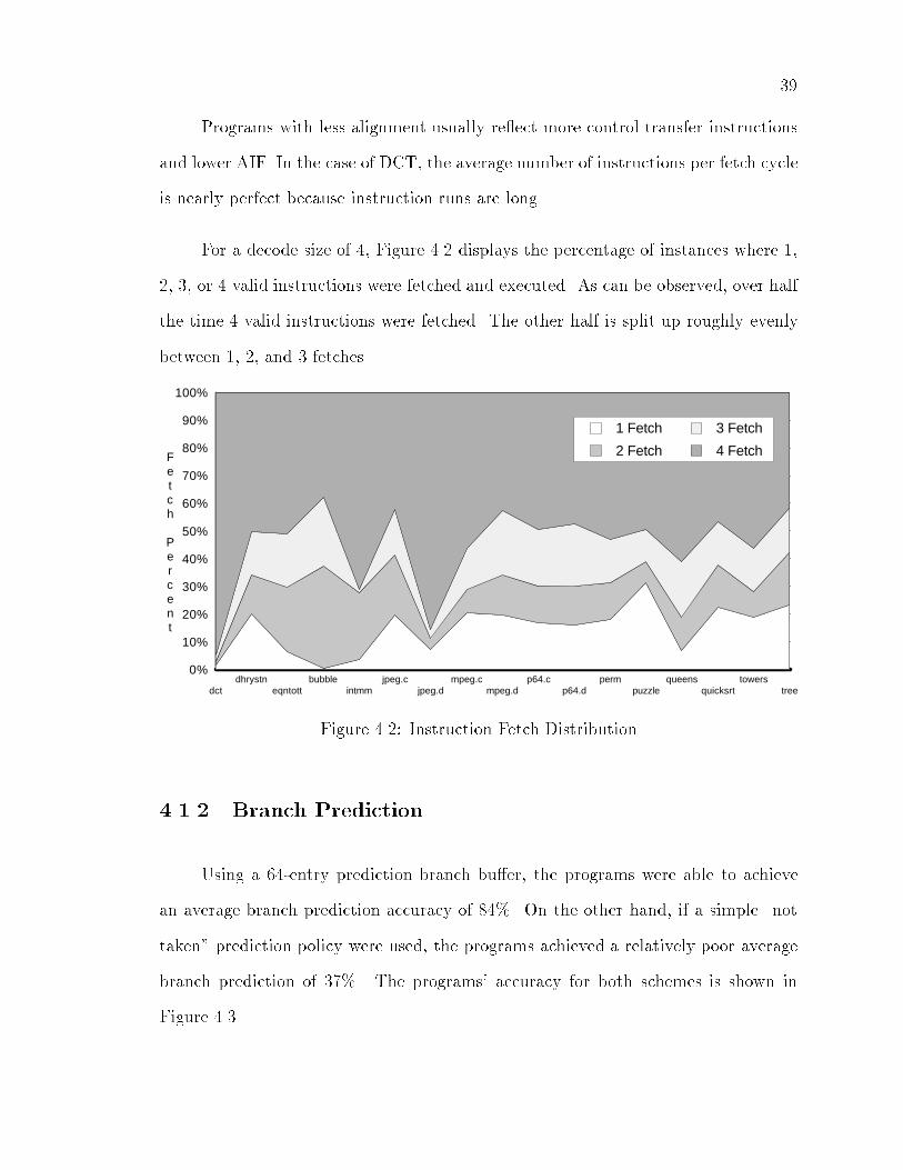
For a decode size of � Figure � displays the percentage of instances where ��
� �� or valid instructions were fetched and executed� As can be observed� over half
the time valid instructions were fetched� The other half is split up roughly evenly
between �� � and � fetches�
0%
10%
20%
30%
40%
50%
60%
70%
80%
90%
100%
dctdhrystn
eqntottbubble
intmmjpeg.c
jpeg.dmpeg.c
mpeg.dp64.c
p64.dperm
puzzlequeens
quicksrttowers
tree
1 Fetch
2 Fetch
3 Fetch
4 FetchFetch Percent
Figure �� Instruction Fetch Distribution
����� Branch Prediction
Using a � �entry prediction branch bu�er� the programs were able to achieve
an average branch prediction accuracy of � � On the other hand� if a simple �not
taken� prediction policy were used� the programs achieved a relatively poor average
branch prediction of �� � The programs� accuracy for both schemes is shown in
Figure ���

�
One way to handle branches is to execute them in�order when the branch reaches
the bottom of the SU� If a branch is mispredicted� the entire reorder bu�er and
instruction window are invalidated and execution resumes at the correct location�
The penalty associated with a mispredicted branch would be the depth of the SU�
This penalty is constant and grows linearly with respect to the size of the SU�
Alternatively� if the SU recovered from a mispredicted branch as soon as the
outcome was known� substantial savings could be achieved� Table �� shows the
average bad branch cycle penalty for Scheduling Unit depth of � � �� and �� using
this method with a � �entry branch prediction bu�er as described in Chapter �
The bad branch cycle penalty is the number of incorrectly fetched blocks� plus
an additional cycle penalty for branches mispredicted taken that are not on the last
decoder position� since it must refetch the same block upon recovery� On the other
hand� cycles that stalled due to data dependencies in the Scheduling Unit are not
considered part of the branch penalty� For instance� if after a mispredicted branch the
SU stalls a cycle and resolves that branch� the Instruction Unit will resume fetching
the correct block and will have never fetched an incorrect block� Hence� there is
no penalty associated with that misprediction� since a correct prediction would have
resulted in identical performance� This is how an average penalty of less than one
cycle can be achieved�
����� Instruction Cache
Instruction fetching must be sustained� or it will be impossible to achieve a
high Instructions Per Cycle rate� The instruction cache should supply a new block of
instructions each cycle� Using a direct mapped instruction cache� Figure � shows

�
Program � ��
dct ��� ��� �� ���
dhrystone ��� � � ��
eqntott ��� � � �
bubble ��� ��� �� ��
intmm ��� ��� �� ���
jpeg�c ��� ��� �� ��
jpeg�d ��� � � ��
mpeg�c ��� � �� ���
mpeg�d ��� � �� ���
p� �c ��� �� ��� ���
p� �d ��� ��� ��� ���
perm ��� ��� ��� ���
puzzle ��� �� �� ��
queens ��� �� ��� ���
quicksort ��� � �� ��
towers ��� ��� ��� ���
tree ��� �� �� ���
Average ��� �� �� ���
Table ��� Average Bad Branch Penalty Cycles vs� SU depth

0%
20%
40%
60%
80%
100%
dctdhrystn
eqntottbubble
intmmjpeg.c
jpeg.dmpeg.c
mpeg.dp64.c
p64.dperm
puzzlequeens
quicksrttowers
tree
41%
61%
15%
26%
3%
19%
26%
40%
15%
31%
51%
63%
8%
52%
40%
75%
42%
92%
79%
96%93% 95%
91% 92%
84%
92%87%
93%
74%
95%
65%
89%
96%
89%
Predict "not-taken"
SDSP Predictor
Accuracy
Figure ��� Branch Prediction Accuracy
the miss rate� Only the digital signal applications had a high enough miss rate to
be considered� The rest� including the Stanford benchmarks� have a miss rate of less
than ��� � An instruction cache of at least KB is needed for a tolerable miss rate�
Otherwise� performance loss due to instruction cache misses su�ers dramatically at
high miss rates�
��� Scheduling Unit
This section is concerned with the performance of the Scheduling Unit� The
Scheduling Unit needs to be able to issue the majority of the ready�to�run instructions
or else instructions will pile up� Furthermore� if the results are not able to write to
the SU and activate additional instructions� this will reduce the ready�to�run pool of
instructions� Also� if the Scheduling Unit depth is not large enough� it does not look�
ahead enough to extract parallelism� and the SU will stall due to data dependencies�

�
0%
2%
4%
6%
8%
10%
12%
14%
16%
18%
1k 2k 4k 8k 16k
jpeg.c jpeg.d
mpeg.c mpeg.d
p64.c p64.d
stanford
Miss Rate
Figure � � Instruction Cache Miss Ratio vs Size

����� SU Depth
Figure � shows the overall speedup using a SU depth of � � �� and �� for all
the programs� The speedup di�erence between SU depth of and is substantial�
The increase from a depth from to � is signi�cant in most cases� Comparing the
speedup using SU depth of � to the average fetch count� as in Figure ��� shows that
most programs have come close to reaching their maximum potential speedup� The
di�erence is usually from mispredicted branch delays� If there is still a signi�cant
di�erence� increasing the SU depth to �� will reduce this gap� as noticed with dct�
intmm� and jpegd� Otherwise it will make no di�erence and can actually reduce
speedup slightly as in the case with bubble� perm� puzzle� quicksort� and treesort� The
loss in speedup is from a decrease in branch prediction accuracy� Branch prediction
statistics are updated when a block of instructions is shifted out of the SU� Therefore�
accuracy is sometimes lost when increasing the SU depth because this increases the
latency required for update�
1.5
2.0
2.5
3.0
3.5
4.0
dctdhrystn
eqntottbubble
intmmjpeg.c
jpeg.dmpeg.c
mpeg.dp64.c
p64.dperm
puzzlequeens
quicksrttowers
tree
1.82 1.851.73
1.671.55
1.701.80
1.89
1.73
1.90
1.77
2.03
1.611.70
2.00
1.85
2.542.47
2.22
2.37
2.14
2.31
2.53
2.402.30
2.462.36
2.64
2.44
2.01
2.26
2.69
2.40
2.99
2.67
2.92
2.65
2.96
2.44
3.04
2.64
2.46
2.59 2.57
2.86
2.58
2.11
2.54
3.07
2.52
3.84
2.72
2.97
2.62
3.33
2.55
3.47
2.682.56
2.67 2.67
2.82
2.53
2.11
2.53
3.07
2.49
248
16
Speedup
SUDepth
SUDepth
SUDepth
Figure �� Speedup Improvement

����� Issue�Result Write Limit
The SDSP uses complete bypassing of results to functional units to avoid extra
latency� This� however� is costly in hardware� Figure �� shows the performance e�ect
without bypassing compared to complete bypassing used in the base machine� As can
be observed� bypassing has a two to three times savings in the number of stall cycles�
This is a signi�cant performance savings� Another way of looking at it is that the size
of the SU needs to be over twice as large if bypassing is not used to get equivalent
performance� For example� as shown in the �gure� at a SU depth of � with bypassing
would require a SU depth of � without bypassing for the same percentage of SU stalls�
Hence� using bypassing is worthwhile since the extra space in layout is signi�cantly
less than a doubling of the size of the SU�
0 0
10 10
20 20
30 30
40 40
50 50
60 60
70 70
2 3 4 5 6 7 8
Base
W/O Bypassing
% Stalls
Figure ��� Percentage Stalls vs� SU Depth

�
Figure �� shows the percentage di�erence between allowing or � �identical
outcome� result writes per cycle compared to the base case of � Since up to �
instructions may be issued in a cycle� a maximum of � results may be ready to be
written in a cycle� Allowing result writes increased performance for many programs�
especially for dct� eqntott� jpegc� and mpegc where over a �� increase in speedup
is observed� For the bubble� intmm� p�c� perm� queens� and quicksort programs�
however� absolutely no di�erence resulted from allowing result writes� Programs
with a sizable di�erence between AIF �Figure ��� and the base speedup �Figure ��
SU � �� showed the greatest improvement� The case of � result write never occurred
which implies is the real maximum� Therefore� a � result write limit is unnecessary
and wasteful�
0%
2%
4%
6%
8%
10%
12%
14%
dctdhrystn
eqntottbubble
intmmjpeg.c
jpeg.dmpeg.c
mpeg.dp64.c
p64.dperm
puzzlequeens
quicksrttowers
tree
10.7%
5.0%
12.7%
0.0% 0.0%
2.0%
11.4%
10.2%
5.4%
0.0%
6.1%
0.0%
3.2%
0.0% 0.0%
2.7%
0.5%
5,6 Max Write
% Difference 4
Write
Figure ��� Performance for Write Result Increase
Figure �� shows the issue count distribution� The bulk is evenly distributed
between two� three� and four issue count� which would appear to average out to about
three� About � of the time only one instruction can be issued� The low instruction
issue count is partly due to fetch ine�ciencies and data dependencies� On the other

�
hand� approximately �� of the time �ve or six instructions are issued� When �ve
or six instructions are issued� the average is balanced from the cases where only one�
two� or three instructions are issued so that the overall instructions issued per cycle
is closer to four� Therefore� increasing the maximum issue count above the decode
size does increase performance�
The instructions issued beyond four ALUs can be a load� store� multiply� or
control transfer� Since store and control transfer operations do not have a result�
increasing the maximum issue count without increasing the maximum write count
can improve IPC� To receive bene�t from when an extra load or multiply instruction
is issued� one must increase the maximum result write per cycle as has been shown
previously�
0%
10%
20%
30%
40%
50%
60%
70%
80%
90%
100%
dctdhrystn
eqntottbubble
intmmjpeg.c
jpeg.dmpeg.c
mpeg.dp64.c
p64.dperm
puzzlequeens
quicksrttowers
tree
1 Issue
2 Issue
3 Issue
4 Issue
5 Issue
6 Issue
Issue Percent
Figure ��� Issue Count Distribution

�
��� Execution Unit
Execution Unit issues in performance cannot be ignored� If a slow functional
unit or not enough functional units of a particular type are used� a decline in perfor�
mance will be observed� This section considers issues involving the data cache� ALU�
multiplier� and load and store units�
����� ALU
Since only three instructions are executed per cycle on the average� does it
make sense to use four ALUs instead of just three� On the other hand� since it is
possible to issue more than four instructions a cycle� perhaps having �ve ALUs will
avoid unnecessary stalls� To determine this� Figure �� shows the speedup decrease
percentage from using or � ALUs compared to using the base case of ALUs�
keeping the result write limit constant at � Using only ALUs decreases performance
signi�cantly for almost all cases since it cannot meet the resource needs of the SU�
On the other hand� � ALUs performs almost identically to ALUs� except for ALU�
intensive programs such as dct and jpegd� The average speedup is less than ��� for
most programs� Logically� � ALUs should su�ce for these cases since a large SU can
compensate for waiting ALU instructions� Using ALUs and a result write limit
can create a write con�ict with a load or multiply operation� Eliminating one ALU
removes this con�ict�
A more fair comparison is to isolate the ALU usage by allowing more result
writes than ALUs to remove write con�icts with loads and multiplies� Figure ���
displays the performance di�erence of using � �� or ALUs compared to ALUs�

�
-24.0%
-20.0%
-16.0%
-12.0%
-8.0%
-4.0%
0.0%
dctdhrystn
eqntottbubble
intmmjpeg.c
jpeg.dmpeg.c
mpeg.dp64.c
p64.dperm
puzzlequeens
quicksrttowers
tree
2 ALU3 ALU
% Difference 4 ALU
Figure ��� Performance Decrease from ALUs� Write Limit Constant
Note� the basis for comparison uses ALUs with result writes which is di�erent
from the previous �gure� In addition� the items compared have enough result write
bandwidth so no write con�icts arise�
Programs that execute over �� ALU �refer to Figure ��� operations and have
a high average fetch count �refer to Figure ��� have the greatest change in per�
formance when ALU resources change� Those programs �dct� eqntott� and jpegd�
bene�t signi�cantly from using ALUs� Now that the full potential of ALUs is
represented� � and especially ALUs show dramatic performance decrease� although
some programs� performance does not decline as much�
����� Multiplier
Since multiplication is used quite frequently in digital signal processing� one
multiplier may not be enough to avoid delays� Figure ��� shows the performance

�
-25.0%
-20.0%
-15.0%
-10.0%
-5.0%
0.0%
5.0%
10.0%
15.0%
dctdhrystn
eqntottbubble
intmmjpeg.c
jpeg.dmpeg.c
mpeg.dp64.c
p64.dperm
puzzlequeens
quicksrttowers
tree
2 ALU
3 ALU
5 ALU
% Difference 4 ALU
Figure ���� Performance Di�erence Compared to ALUs� Write Limit Varied
increase using multiplier units over � multiplier unit� A performance increase is
observed only for the DSP applications �DCT� JPEG� MPEG� P� � and intmm� DCT
showed the greatest increase followed by P� and JPEG� This increase varied from
� to � which translates to a ��� to �� IPC increase� Overall� using multipliers
did not prove worthwhile�
����� Load�Store
Load operations can be critical because usually many following instructions
depend on it� If a load has to wait because of a resource con�ict� all its dependents
will also have to wait� Currently� only one load operation may be done in a cycle�
Store instructions may be issued once per cycle� That rate cannot be sustained since

�
0.0%
2.0%
4.0%
6.0%
8.0%
10.0%
dctdhrystn
eqntottbubble
intmmjpeg.c
jpeg.dmpeg.c
mpeg.dp64.c
p64.dperm
puzzlequeens
quicksrttowers
tree
7.4%
0.0% 0.0% 0.0%
10.0%
4.0%
1.3%
0.7%
3.1%
1.5%
4.4%
0.0% 0.0% 0.0% 0.0% 0.0% 0.0%
2 Multipliers% Increase Base
Figure ���� Performance Increase Using Multipliers
both load and store instructions share the data cache and load instructions have
priority� If� on the average� only one quarter of the instructions are load and store
instructions� a single data port cache should su�ce� Problems arise when two or more
load or store instructions are ready to be issued at the same time�
Using a two�port data cache will expand the load�store bandwidth and can
reduce stalls� Figure �� compares the speedup of using two load and two store units
versus one load and one store unit� A few cases which have many consecutive load
or store operations such as dct and queens have a signi�cant increase in performance�
but for most cases the increase was less than one percent� It should be noted� since
the store bu�er over�ows were ignored in the simulator� programs with both high
load and store content would bene�t more than is shown in the �gure� Therefore� one
will have to weigh the costs involved before implementing a two�port data cache�

0.0%
1.0%
2.0%
3.0%
4.0%
5.0%
6.0%
7.0%
8.0%
dctdhrystn
eqntottbubble
intmmjpeg.c
jpeg.dmpeg.c
mpeg.dp64.c
p64.dperm
puzzlequeens
quicksrttowers
tree
7.4%
1.0%1.3%
0.7%
0.0%
1.2%
0.4%0.6%
1.5%
0.5%
1.8%
0.0%0.4%
3.9%
0.4%0.1% 0.2%
2 Load, 2 Store
% Increase Base
Figure ��� Performance Increase Using Load and Store Units
����� Data Cache
Data must be quickly accessible� or else poor performance will result since there
will be nothing to compute� A data cache provides a one cycle load and store opera�
tion� It� however� must perform satisfactorily when data cache misses are encountered�
A data cache miss on a load e�ects the rest of the processor since the result value will
not be available for further computation by other instructions� This can cause the
Scheduling Unit to eventually stall� Using a write through data cache with a � cycle
miss penalty� Figure ��� shows data cache miss ratio from � KB to �� KB cache
size� The programs not shown had less than a ��� miss ratio� � KB to KB is
unacceptable� � KB or �� KB yields a reasonable miss ratio� Unlike the instruction
cache� the data cache has a much higher overall miss ratio for the same size cache� A
�� KB cache size is preferred since it lowers the miss ratio for most cases below �

�
0%
4%
8%
12%
16%
20%
24%
28%
1k 2k 4k 8k 16k
eqntott jpeg.c
jpeg.d mpeg.c
mpeg.d p64.c
p64.d puzzle
quicksrt tree
Miss Rate
Figure ���� Data Cache Miss Ratio vs Size

��� Overall Analysis
The overall performance is determined by several factors�
� Instruction cache miss cycles� Delayi�cache�
� Cycles delayed from data cache misses� Delayd�cache�
� Bad branch prediction penalty cycles� Delaybranch�
� Scheduling Unit stall cycles� StallSU�
� Loss of potential instructions from fetch ine�ciency� Lossfetch�
The Instructions Per Cycle� IPC� is related to the size of the instruction fetch
block� Sizeblock� and Utilization by
IPC � Sizeblock � Utilization
where
Utilization �������Delayi�cache��Delayd�cache��Delaybranch��StallSU��Lossfetch
or equivalently related to the Average Instruction Fetch� AIF � by
IPC � AIF � ���� � Delayi�cache � Delayd�cache � Delaybranch � StallSU�
All percentages are relative to the total number of cycles� These percentages
change dynamically� but should not vary widely� The factors are mutually indepen�
dent� except for some dependence between cache delays and SU stalls�
Table � shows the distribution of these factors that contribute to performance
degradation� All programs used default parameters except with an � KB instruction

cache and � KB data cache� Appendix E gives detailed results from the original
output of the simulator for this case�
Figure �� is a pie chart showing the factors contributing to overall perfor�
mance� On average� the delays cause by instruction and data cache misses were less
than � Only of the time was there a Scheduling Units stall� There was roughly
a � penalty due to mispredicted branches� A loss in speedup due to fetching in�
e�ciently was the greatest factor� leaving � utilization of a potential four times
speedup�
Utilization 63.8%
Fetch 18.5%
SU 5.3%
Branch 8.6%
D-cache 1.8%I-cache 2.1%
Figure �� � Overall Performance Factors

�
Program AIF Icache Dcache Bra SU Fetch IPC
dct ���� ��� ���� �� �� ��� ���
dhrystone ��� ���� ���� ��� �� �� ��
eqntott ���� �� ���� �� �� ���� ��
bubble ���� ���� ���� ���� ��� �� ��
intmm ���� ���� �� �� ��� ��� ���
jpeg�c ��� �� ���� ��� ��� �� �
jpeg�d ���� ��� ��� � ���� �� ��
mpeg�c ���� � ���� ��� � ���� ��
mpeg�d ��� � ��� �� ��� ��� �
p� �c ��� ���� ��� ���� �� ��� � �
p� �d ���� ���� ��� ��� �� ���� �
perm ���� ��� ���� �� ��� �� ���
puzzle ��� ���� ��� ��� ��� �� ���
queens ��� ���� ���� ���� �� ��� ���
quicksort ��� ���� ��� ��� �� �� �
towers ���� ���� ���� ��� ��� � ����
tree ��� ��� �� ��� � � �
Average ���� ��� ���� ��� �� ��� ��
Table �� Performance Factors

Chapter �
Conclusion
This thesis presented the SDSP architecture and analyzed its performance using
di�erent con�gurations� The primary goal of this thesis project is to de�ne a super�
scalar architecture with VLSI design consideration and investigate its performance
issues� Once the performance impact from an architectural issue is known� the de�
cision can be made if the cost in implementation is worth the performance tradeo��
Issues relating to the SDSP�s Instruction Unit� Scheduling Unit� and Execution Unit
were examined separately� Overall� only � of the maximum speedup was able to
be utilized�
One critical factor in the performance of any superscalar is how control �ow
is handled� Using a multiple branch predictor over a simple �not taken� policy
signi�cantly increased the accuracy of instruction �ow� An even more signi�cant
improvement was achieved by reducing the average bad branch penalty� This was
accomplished by correcting program �ow and discarding the speculative execution
as soon as the branch is resolved� As a result� it is possible to have no penalty
associated with a mispredicted branch and an average penalty less than one cycle�
Handling branches e�ectively is paramount to reasonable performance� so adopting a
good branch prediction method� such as presented� is pivotal�
�
�
Increasing the SU depth from to � increases speedup considerably� Continuing
to increase it to �� provided little or no bene�t for most programs� except for programs
with high fetch e�ciency and high ALU content� If bypassing of results is not used� a
SU twice as deep is needed for equivalent performance� Furthermore� increasing the
issue limit beyond the decode size increases performance� The result write limit also
needs to be increased slightly� or else the full bene�t from increasing the issue limit
will not be realized�
Digital signal processing programs bene�ted most using an additional multiplier
or ALU unit� All programs marginally improved using an extra load and store unit�
The exact resource con�guration is really dependent on the types of applications
primarily used on the microprocessor� the base con�guration provided a good overall
performance to cost ratio�
Since the SU shifts in a FIFO manner� and most of the time a good portion of it
goes unused or contains unnecessary information� it would be interesting to �nd out
how to �compress� the SU� keeping only relevant information to maximize the ratio
of parallelism extracted to hardware usage� The most important issue is the average
fetch e�ciency because it is the greatest factor limiting performance� The solution to
this problem is static scheduling of the program so that control transfer instructions
are aligned on decode boundaries� Some research into this has already been done ����
but since the solution is a NP�complete problem� new heuristics need to be developed
to signi�cantly increase AIF within a reasonable period of time�

Bibliography
��� A� Abnous� C� Christensen� J� Gray� J� Lenell� A� Naylor� and N� Bagherzadeh�
�VLSI Design of the TinyRISC Processor��� In Proceedings of the ���� IEEE
Custom Integrated Circuits Conference� pages ��� ��!��� �� ����
�� Mark J� Blair� Asdsp Users s Guide� University of California� Irvine� ����
��� William Brown� �Design and Analysis of a Post�pass Scheduler for a Superscalar
Digital Signal Processor��� Master�s thesis� University of California� Irvine� �����
� � John Ellis� Bulldog� A compiler for VLIW Architectures� The MIT Press�
Cambridge� �����
�� J� Gray� A� Naylor� A� Abnous� and N� Bagherzadeh� �VIPER� A MHz� ���
MIPS Peak VLIW Microprocessor��� In Proceedings of the ���� IEEE Custom
Integrated Circuits Conference� San Diego� �����
��� John Hennessey and David Patterson� Computer Architecture� A Quantitative
Approach� Morgan Kaufmann Publishers� Inc�� San Mateo� �����
��� Sheng�Chieh Huang� �Analysis and Design of a Dynamic Instruction Unit for a
Superscalar Computer Architecture��� Master�s thesis� University of California�
Irvine� �����
��� Mike Johnson� Superscalar Microprocessor Design� Prentice Hall� Englewood
Cli�s� �����
�

��
��� P� M� Kogge� The Architecture of Pipelined Computers� McGraw�Hill� New York�
�����
���� Johnny K� F� Lee and Alan J� Smith� �Branch Prediction Strategies and Branch
Target Bu�er Design��� IEEE Computer� pages �!� ��� �
���� J� Lenell� S� Wallace� and N� Bagherzadeh� �A � MHz CMOS Reorder Bu�er
for a Superscalar Microcomputer��� In �th Annual NASA VLSI Symposium�
November ����
��� John Lenell and Nader Bagherzadeh� �A Performance Comparison of Several
Superscalar Processor Models with a VLIW Processor��� In Proceedings of
International Parallel Processing Symposium� pages ! �� �����
���� Reynold Leong� �Architecture and VHDL Modeling of a Supserscalar
Microprocessor��� Master�s thesis� University of California� Irvine� �����
�� � Motorola Inc� MC����� Second Generation RISC Microprocessor User s
Manual� �����
��� J� E� Smith and A� R� Pleszkun� �Implementing Precise Interrupts in Pipelined
Processors��� IEEE Transactions on Computers� C�����!��� May �����
���� J� E� Thorton� Design of a Computer� CDC ��� Scott� Foresman� Blenview�
IL� �����
���� R� M� Tomasulo� �An E�cient Algorithm for Exploiting Multiple Arithmetic
Units��� IBM Journal of research and Development� January �����
���� Shlomo Weiss and James Smith� �Instruction Issue Logic in Pipelined
Supercomputers��� IEEE Transactions on Computers� c������������!���
November ��� �

Appendix A
Porting GNU CC to the SDSP
The following are instructions on how to port GNU CC �� to compile SDSP
code�
�� First anonymous ftp the original source code from prep�ai�mit�edu� Get the
�le �pub�gnu�gcc��� �tar�gz and extract it�
� Ftp the ported tm�h and md con�guration �les from ece�uci�edu� Get the �le
�pub�swallace�thesis�gcc�sdsp�tar�gz and extract it�
�� Change the con�g�h �le if the host system is not on a SUN and make the
compiler�
��

Appendix B
Porting GNU GAS to the SDSP
The following are instructions on how to port GNU GAS assembler to the SDSP�
�� First anonymous ftp the original source code from prep�ai�mit�edu� Get the
�le �pub�gnu�gas��������tar�gz and extract it�
� Ftp the sdsp�c and sdsp�h machine dependent and other modi�ed �les from
ece�uci�edu in �pub�swallace�thesis�gas�sdsp�tar�gz and extract it�
�� Make the assembler�
�

Appendix C
Porting GNU ld to the SDSP
The following are instructions on how to port GNU �ld� to link SDSP object
modules�
�� Ftp the modi�ed source code from ece�uci�edu in �pub�swallace�thesis�ld�
sdsp�tar�gz and extract it�
� Make the linker�
��

Appendix D
Obtaining SDSP Simulator Source
Code
The following are instructions on how to obtain SDSP simulator code�
�� Ftp the source code from ece�uci�edu in �pub�swallace�thesis�ss�tar�gz and
extract it�
� Make the simulator�
�

Appendix E
Detailed Results
This appendix contains detailed result information as obtained from the SDSP
simulator� The following pages list the statistical output on all programs using the
default parameters with an � KB instruction cache and � KB data cache�
�

��
dct
parms � � � � � �� ���� ���� � � � � �
TOTAL CYCLES ������
TOTAL INTEGER CYCLES ������ ��� ������
TOTAL FLOATING POINT CYCLES � � ������
TOTAL SU STALLS ���� �� ������
TOTAL BRANCH DELAYS ��� � �����
TOTAL ICACHE DELAYS ���� � �����
TOTAL DCACHE DELAYS � � ������
TOTAL DELAYS ���� � �����
INSTRUCTION CACHE MISS RATIO ���������� � � ������
DATA CACHE MISS RATIO ������� � � �������
TOTAL WRITE OVERFLOWS ���� � ������
ISSUE � � � � � � � � �
COUNT ���� ���� ����� ���� ��� ����� ��� � �
� � ��� � ��� �� ��� � �� �� ��� � ��� � ��� � ��� � ���
WRITE � � � � �
COUNT ���� ���� ����� ����� �����
� � ��� � ��� �� ��� ��� �� ���
BRANCH � � � � �
COUNT ����� ���� � � �
� ���� ��� ��� ��� � ��� � ��� � ���
FETCH � � � � �
COUNT � ���� ���� ��� ����
� � ��� � ��� � ��� � �� �� ���
TYPE ALU MULT LOAD STOR CNTL FLPT
COUNT ������ ����� ���� ���� ���� �
� �� ��� ��� � ��� � ��� � ��� � ���
BRANCH PREDICTION RATE � � � ������� � �� ���
AVERAGE BAD BRANCH PENALTY � ������ � �
AVERAGE RESULT WRITE � ����
INSTRUCTION COUNT ������
AVERAGE FETCH COUNT � ������������� � ����
FETCH DEFICIT� LOSS � ������ � �����
IPC �Int � FP� � ����
IPC �Integer� � ����
SPEEDUP � ����

��
dhrystone
parms � � � � � �� ���� ���� � � � � �
TOTAL CYCLES �����
TOTAL INTEGER CYCLES ����� ��� ������
TOTAL FLOATING POINT CYCLES � � ������
TOTAL SU STALLS ����� � �����
TOTAL BRANCH DELAYS ���� � ������
TOTAL ICACHE DELAYS ���� � �����
TOTAL DCACHE DELAYS � � ������
TOTAL DELAYS ������ �� �����
INSTRUCTION CACHE MISS RATIO ���������� � � ������
DATA CACHE MISS RATIO �������� � � �������
TOTAL WRITE OVERFLOWS ������ ������
ISSUE � � � � � � � � �
COUNT ���� ������ ������ ������ ������ ������ � � �
� � �� �� ��� �� ��� �� ��� �� �� � ��� � ��� � ��� � ���
WRITE � � � � �
COUNT ����� ������� ������ ������ ������
� �� �� �� �� �� ��� �� ��� � ���
BRANCH � � � � �
COUNT ������� ����� � � �
� �� ��� ��� ��� � ��� � ��� � ���
FETCH � � � � �
COUNT � ������ ������ ������ �������
� � ��� �� ��� �� ��� �� ��� �� ��
TYPE ALU MULT LOAD STOR CNTL FLPT
COUNT ������� ����� ����� ������� ������ �
� �� ��� � ��� �� ��� �� ��� �� �� � ���
BRANCH PREDICTION RATE � � � ������������ � �� ���
AVERAGE BAD BRANCH PENALTY � ����������� � � �
AVERAGE RESULT WRITE � ���
INSTRUCTION COUNT ������
AVERAGE FETCH COUNT � ������������� � ����
FETCH DEFICIT� LOSS �� ����� �� �����
IPC �Int � FP� � ���
IPC �Integer� � ���
SPEEDUP � ���

��
eqntott
parms � � � � � �� ���� ���� � � � � �
TOTAL CYCLES ������
TOTAL INTEGER CYCLES ������ ��� ������
TOTAL FLOATING POINT CYCLES � � ������
TOTAL SU STALLS ����� ������
TOTAL BRANCH DELAYS ���� � ������
TOTAL ICACHE DELAYS ���� ������
TOTAL DCACHE DELAYS ����� � ������
TOTAL DELAYS ���� � ����
INSTRUCTION CACHE MISS RATIO ����������� � � �������
DATA CACHE MISS RATIO ���������� � � ������
TOTAL WRITE OVERFLOWS ���� � ������
ISSUE � � � � � � � � �
COUNT ����� ����� ����� ������ ������ ����� ���� � �
� ��� � ��� �� ��� � ��� �� ��� � ��� � ��� � ��� � ���
WRITE � � � � �
COUNT ���� ������ ����� ��� �����
� � ��� �� �� ��� � ��� � ���
BRANCH � � � � �
COUNT ������ ������ ���� � �
� ��� ��� �� ��� � ��� � ��� � ���
FETCH � � � � �
COUNT � ����� ������ ����� ������
� � ��� � ��� � �� �� ��� �� ��
TYPE ALU MULT LOAD STOR CNTL FLPT
COUNT ������ ��� ����� ���� ����� �
� �� ��� � ��� �� ��� � ��� �� ��� � ���
BRANCH PREDICTION RATE � � � ������������ � �� ���
AVERAGE BAD BRANCH PENALTY � ���������� � � �
AVERAGE RESULT WRITE � ���
INSTRUCTION COUNT ������
AVERAGE FETCH COUNT � ������������� � ����
FETCH DEFICIT� LOSS �� ������ �� ������
IPC �Int � FP� � ���
IPC �Integer� � ���
SPEEDUP � ���

��
bubble
parms � � � � � �� ���� ���� � � � � �
TOTAL CYCLES �����
TOTAL INTEGER CYCLES ����� �� �����
TOTAL FLOATING POINT CYCLES �� � �����
TOTAL SU STALLS ��� � ������
TOTAL BRANCH DELAYS ����� �� ������
TOTAL ICACHE DELAYS �� � ������
TOTAL DCACHE DELAYS � � ������
TOTAL DELAYS ����� �� ������
INSTRUCTION CACHE MISS RATIO ��������� � � �������
DATA CACHE MISS RATIO �������� � � �����
TOTAL WRITE OVERFLOWS � � ������
ISSUE � � � � � � � � �
COUNT ��� ������ ������ ���� ������ � � �
� � ��� �� ��� �� �� �� ��� � ��� � ��� � ��� � ��� � ���
WRITE � � � � �
COUNT ����� ����� ����� ������ �
� ��� ��� �� �� � �� � ���
BRANCH � � � � �
COUNT ������ ������ � � �
� ��� ��� ��� ��� � ��� � ��� � ���
FETCH � � � � �
COUNT � ���� ������ ������ �����
� � ��� � ��� � ��� �� �� � ���
TYPE ALU MULT LOAD STOR CNTL FLPT
COUNT ������ ���� ����� ������ ����� ��
� �� �� � ��� �� ��� � ��� �� ��� � ���
BRANCH PREDICTION RATE � � � ������������ � � ��
AVERAGE BAD BRANCH PENALTY � ����������� � � �
AVERAGE RESULT WRITE � ����
INSTRUCTION COUNT ������
AVERAGE FETCH COUNT � ������������� � � ���
FETCH DEFICIT� LOSS �� ����� �� �����
IPC �Int � FP� � ����
IPC �Integer� � ����
SPEEDUP � ���
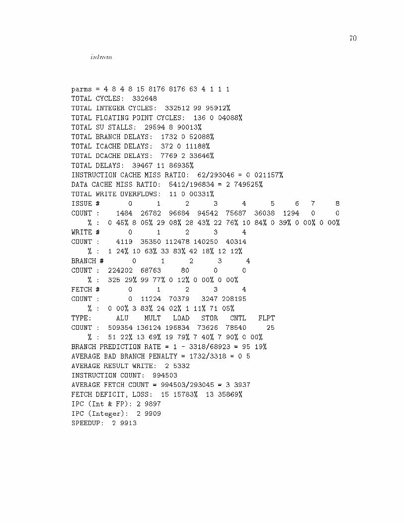
��
intmm
parms � � � � � �� ���� ���� � � � � �
TOTAL CYCLES ����
TOTAL INTEGER CYCLES ���� �� ������
TOTAL FLOATING POINT CYCLES �� � ������
TOTAL SU STALLS ����� � �����
TOTAL BRANCH DELAYS ��� � ������
TOTAL ICACHE DELAYS �� � ������
TOTAL DCACHE DELAYS ���� � ����
TOTAL DELAYS ���� �� �����
INSTRUCTION CACHE MISS RATIO �������� � � �������
DATA CACHE MISS RATIO ���������� � � �������
TOTAL WRITE OVERFLOWS �� � ����
ISSUE � � � � � � � � �
COUNT ���� ����� ����� ����� ����� ��� ���� � �
� � ��� � ��� �� ��� �� �� �� ��� �� ��� � �� � ��� � ���
WRITE � � � � �
COUNT ���� ��� ������ ������ ����
� � ��� �� �� �� �� ��� �� ���
BRANCH � � � � �
COUNT ������ ���� �� � �
� �� ��� �� ��� � ��� � ��� � ���
FETCH � � � � �
COUNT � ����� ���� ��� ������
� � ��� �� �� ��� � ��� �� ���
TYPE ALU MULT LOAD STOR CNTL FLPT
COUNT ����� ����� ����� ���� ����� ��
� �� ��� � ��� �� ��� � ��� � ��� � ���
BRANCH PREDICTION RATE � � � ������� � �� ���
AVERAGE BAD BRANCH PENALTY � ������ � � �
AVERAGE RESULT WRITE � ��
INSTRUCTION COUNT �����
AVERAGE FETCH COUNT � ����������� � ��
FETCH DEFICIT� LOSS �� ����� � �����
IPC �Int � FP� � ����
IPC �Integer� � ����
SPEEDUP � ���

��
jpegc
parms � � � � � �� ���� ���� � � � � �
TOTAL CYCLES ������
TOTAL INTEGER CYCLES ������ ��� ������
TOTAL FLOATING POINT CYCLES � � ������
TOTAL SU STALLS ������ � ������
TOTAL BRANCH DELAYS ������ � ������
TOTAL ICACHE DELAYS ����� � ������
TOTAL DCACHE DELAYS ����� � ������
TOTAL DELAYS ������� �� �����
INSTRUCTION CACHE MISS RATIO ����������� � � ������
DATA CACHE MISS RATIO ������������� � � �������
TOTAL WRITE OVERFLOWS ����� � �����
ISSUE � � � � � � � � �
COUNT ���� ������ ������ ������ ������ ���� ���� � �
� � ��� �� ��� �� ��� �� ��� �� ��� � ��� � ��� � ��� � ���
WRITE � � � � �
COUNT ����� ������� ������� ���� �����
� �� ��� � ��� � ��� � ��� � ���
BRANCH � � � � �
COUNT ������ ������� ���� � �
� ��� ��� � �� �� � ��� � ���
FETCH � � � � �
COUNT � ����� ����� ������ �������
� � ��� �� ��� �� ��� �� ��� �� ���
TYPE ALU MULT LOAD STOR CNTL FLPT
COUNT ������� ������ ������� ������ ������� �
� �� ��� � ��� �� ��� � ��� �� �� � ���
BRANCH PREDICTION RATE � � � ������������ � �� ���
AVERAGE BAD BRANCH PENALTY � ������������� � � �
AVERAGE RESULT WRITE � ���
INSTRUCTION COUNT ��������
AVERAGE FETCH COUNT � ������������� � � ���
FETCH DEFICIT� LOSS �� ����� �� ����
IPC �Int � FP� � ����
IPC �Integer� � ����
SPEEDUP � ����

�
jpegd
parms � � � � � �� ���� ���� � � � � �
TOTAL CYCLES �������
TOTAL INTEGER CYCLES ������� �� ������
TOTAL FLOATING POINT CYCLES � � ������
TOTAL SU STALLS ��� � ������
TOTAL BRANCH DELAYS ����� � ������
TOTAL ICACHE DELAYS ������ � ������
TOTAL DCACHE DELAYS ���� ������
TOTAL DELAYS ������ �� ������
INSTRUCTION CACHE MISS RATIO ������������ � � �������
DATA CACHE MISS RATIO ����������� � �������
TOTAL WRITE OVERFLOWS ������ � �����
ISSUE � � � � � � � � �
COUNT ����� ����� ����� ������ ������ ����� ���� �� �
� � ��� � ��� �� ��� �� ��� � ��� � ��� � ��� � ��� � ���
WRITE � � � � �
COUNT ������ ���� ����� ������ ������
� � ��� �� �� � �� �� ��� �� ��
BRANCH � � � � �
COUNT ������ ������ �� � �
� ��� �� �� ��� � ��� � ��� � ���
FETCH � � � � �
COUNT � ���� ����� ��� �������
� � ��� � ��� � ��� ��� �� ���
TYPE ALU MULT LOAD STOR CNTL FLPT
COUNT ������� ����� ������ ������ ������ �
� �� ��� � ��� �� ��� � ��� ��� � ���
BRANCH PREDICTION RATE � � � �������� � �� ��
AVERAGE BAD BRANCH PENALTY � ��������� � � �
AVERAGE RESULT WRITE � ����
INSTRUCTION COUNT ������
AVERAGE FETCH COUNT � �������������� � ����
FETCH DEFICIT� LOSS � ����� � ����
IPC �Int � FP� � ��
IPC �Integer� � ��
SPEEDUP � ���

��
mpegc
parms � � � � � �� ���� ���� � � � � �
TOTAL CYCLES ���������
TOTAL INTEGER CYCLES �������� �� �����
TOTAL FLOATING POINT CYCLES ��������� � ������
TOTAL SU STALLS ������� � ������
TOTAL BRANCH DELAYS ������� �� ������
TOTAL ICACHE DELAYS �������� � ����
TOTAL DCACHE DELAYS ������� � ������
TOTAL DELAYS ��������� �� �����
INSTRUCTION CACHE MISS RATIO ��������������� � � �������
DATA CACHE MISS RATIO ����������������� � � ������
TOTAL WRITE OVERFLOWS ������ � �����
ISSUE � � � � � �
COUNT ������� ��������� ������ ��������� ������� ��������
� � �
������� �� �
� � �� �� ��� �� ��� �� ��� �� ��� � ��� � �� � ��� � ���
WRITE � � � � �
COUNT �������� �������� ������� ����� ��������
� � ��� �� ��� �� ��� �� ��� �� ��
BRANCH � � � � �
COUNT ������� �������� ������ � �
� ��� ��� �� ��� � �� � ��� � ���
FETCH � � � � �
COUNT � �������� �������� ������ ��������
� � ��� �� ��� � ��� �� ��� �� ���
TYPE ALU MULT LOAD STOR CNTL FLPT
COUNT ������� �������� ��������� ������� �������� ��������
� �� ��� � �� �� ��� � ��� �� ��� � ���
BRANCH PREDICTION RATE � � � ��������������� � � ��
AVERAGE BAD BRANCH PENALTY � ��������������� � �
AVERAGE RESULT WRITE � ����
INSTRUCTION COUNT ���������
AVERAGE FETCH COUNT � ������������������ � ���
FETCH DEFICIT� LOSS �� ������ �� �����
IPC �Int � FP� � ����
IPC �Integer� � ��
SPEEDUP �� ���

�
mpegd
parms � � � � � �� ���� ���� � � � � �
TOTAL CYCLES ��������
TOTAL INTEGER CYCLES �������� ��� ������
TOTAL FLOATING POINT CYCLES � � ������
TOTAL SU STALLS ������ � ������
TOTAL BRANCH DELAYS ��� � ������
TOTAL ICACHE DELAYS ���� � ������
TOTAL DCACHE DELAYS ������� � ������
TOTAL DELAYS �������� �� ������
INSTRUCTION CACHE MISS RATIO �������������� � � �������
DATA CACHE MISS RATIO ������������ � � �������
TOTAL WRITE OVERFLOWS ������ � ������
ISSUE � � � � � � �
COUNT ������� ������� �������� ������� ������� ������� �����
� � ��� �� ��� �� ��� �� ��� � �� ��� � ��
� �
���� �
WRITE � � � � �
COUNT ������� ������� ����� ����� �������
� �� ��� � ��� � �� �� ��� � ��
BRANCH � � � � �
COUNT ������� �������� ����� � �
� �� ��� �� ��� � ��� � ��� � ���
FETCH � � � � �
COUNT � ������ ������ �������� �����
� � ��� �� ��� �� ��� � ��� �� ��
TYPE ALU MULT LOAD STOR CNTL FLPT
COUNT �������� ������ �������� ������� ������ �
� �� �� � �� �� ��� � ��� �� ��� � ���
BRANCH PREDICTION RATE � � � ��������������� � �� ��
AVERAGE BAD BRANCH PENALTY � ���������� � �
AVERAGE RESULT WRITE � ����
INSTRUCTION COUNT ��������
AVERAGE FETCH COUNT � ���������������� � � ����
FETCH DEFICIT� LOSS �� ������ �� �����
IPC �Int � FP� � ����
IPC �Integer� � ����
SPEEDUP � ����

�
p�c
parms � � � � � �� ���� ���� � � � � �
TOTAL CYCLES ������
TOTAL INTEGER CYCLES �������� �� ������
TOTAL FLOATING POINT CYCLES �������� � ������
TOTAL SU STALLS ������� � ������
TOTAL BRANCH DELAYS �������� �� ������
TOTAL ICACHE DELAYS ������� ����
TOTAL DCACHE DELAYS ������� � �����
TOTAL DELAYS ������� �� ������
INSTRUCTION CACHE MISS RATIO �������������� � � ������
DATA CACHE MISS RATIO �������������� � � ������
TOTAL WRITE OVERFLOWS ������� � �����
ISSUE � � � � � � �
COUNT ������� �������� ������� �������� ������� �������� ������
� � ��� �� �� �� ��� ��� � ��� � �� � ��
� �
���� �
WRITE � � � � �
COUNT ������� ������ ������� ������� ������
� � ��� �� ��� �� �� �� ��� �� ���
BRANCH � � � � �
COUNT ��������� �������� ������ � �
� ��� �� �� ��� � ��� � ��� � ���
FETCH � � � � �
COUNT � ������� ������ �������� ��������
� � ��� �� ��� � ��� �� ��� �� ���
TYPE ALU MULT LOAD STOR CNTL FLPT
COUNT ��������� ������� �������� �������� �������� ��������
� �� ��� � �� �� ��� � ��� �� ��� � ���
BRANCH PREDICTION RATE � � � ��������������� � �� ���
AVERAGE BAD BRANCH PENALTY � ��������������� � �
AVERAGE RESULT WRITE � ����
INSTRUCTION COUNT ���������
AVERAGE FETCH COUNT � ������������������� � ���
FETCH DEFICIT� LOSS �� ����� �� ������
IPC �Int � FP� � ����
IPC �Integer� � ���
SPEEDUP � ����

��
p�d
parms � � � � � �� ���� ���� � � � � �
TOTAL CYCLES �������
TOTAL INTEGER CYCLES ������� ��� ������
TOTAL FLOATING POINT CYCLES � � ������
TOTAL SU STALLS ������ � ����
TOTAL BRANCH DELAYS ����� � �����
TOTAL ICACHE DELAYS ����� � ������
TOTAL DCACHE DELAYS ������ � �����
TOTAL DELAYS ������� �� ������
INSTRUCTION CACHE MISS RATIO ������������ � � ������
DATA CACHE MISS RATIO �������������� � � �������
TOTAL WRITE OVERFLOWS ������� ������
ISSUE � � � � � � �
COUNT ������� ������ ������� ������ ����� ������� ������
� � ��� �� ��� � �� � ��� � ��� ��� � ���
� �
��� �
WRITE � � � � �
COUNT ����� ������� ������� ������ ����
� � ��� � ��� � ��� �� ��� � ���
BRANCH � � � � �
COUNT �������� ������� ���� � �
� �� ��� �� ��� � ��� � ��� � ���
FETCH � � � � �
COUNT � ������ ������� ������ ������
� � ��� �� �� �� �� �� ��� �� ���
TYPE ALU MULT LOAD STOR CNTL FLPT
COUNT �������� ������ ������� ������ �������� �
� �� ��� � ��� �� ��� � ��� �� ��� � ���
BRANCH PREDICTION RATE � � � ������������� � �� ��
AVERAGE BAD BRANCH PENALTY � ����������� � �
AVERAGE RESULT WRITE � ����
INSTRUCTION COUNT ��������
AVERAGE FETCH COUNT � ��������������� � ����
FETCH DEFICIT� LOSS �� ������ �� ������
IPC �Int � FP� � ����
IPC �Integer� � ����
SPEEDUP � ����

��
perm
parms � � � � � �� ���� ���� � � � � �
TOTAL CYCLES ����
TOTAL INTEGER CYCLES ���� �� ������
TOTAL FLOATING POINT CYCLES �� � ������
TOTAL SU STALLS � � ������
TOTAL BRANCH DELAYS ����� � �����
TOTAL ICACHE DELAYS � � ������
TOTAL DCACHE DELAYS � � ������
TOTAL DELAYS ����� � �����
INSTRUCTION CACHE MISS RATIO ��������� � � �������
DATA CACHE MISS RATIO ������� � � ������
TOTAL WRITE OVERFLOWS � � ������
ISSUE � � � � � � � � �
COUNT �� ����� ����� ���� ������ ���� � � �
� � ��� ��� �� ��� �� �� �� ��� � ��� � ��� � ��� � ���
WRITE � � � � �
COUNT ����� ����� ����� ������ ���
� � ��� �� �� �� ��� � ��� � ���
BRANCH � � � � �
COUNT ������ ���� � � �
� �� ��� ��� ��� � ��� � ��� � ���
FETCH � � � � �
COUNT � ������ ��� ����� �����
� � ��� �� ��� � ��� �� ��� � ���
TYPE ALU MULT LOAD STOR CNTL FLPT
COUNT ����� � ���� ����� ������ ��
� �� ��� � ��� �� ��� �� ��� � ��� � ���
BRANCH PREDICTION RATE � � � �������� � �� ���
AVERAGE BAD BRANCH PENALTY � ��������� � � �
AVERAGE RESULT WRITE � ����
INSTRUCTION COUNT ������
AVERAGE FETCH COUNT � ������������ � ��
FETCH DEFICIT� LOSS �� ������ �� �����
IPC �Int � FP� � ����
IPC �Integer� � ���
SPEEDUP � ����

��
puzzle
parms � � � � � �� ���� ���� � � � � �
TOTAL CYCLES ������
TOTAL INTEGER CYCLES ����� �� ������
TOTAL FLOATING POINT CYCLES �� � ����
TOTAL SU STALLS ������ � ������
TOTAL BRANCH DELAYS ��� � ������
TOTAL ICACHE DELAYS ��� � ����
TOTAL DCACHE DELAYS ������ � ������
TOTAL DELAYS ������ �� ������
INSTRUCTION CACHE MISS RATIO ��������� � � �����
DATA CACHE MISS RATIO �������������� � � �������
TOTAL WRITE OVERFLOWS ���� � �����
ISSUE � � � � � � � � �
COUNT ������ ������ ������� ������� ������ ���� � � �
� � �� �� �� � ��� � ��� �� ��� � ��� � ��� � ��� � ���
WRITE � � � � �
COUNT ������ ������ ����� ������ �����
� � ��� �� �� �� ��� �� ��� � ���
BRANCH � � � � �
COUNT ������ ������� �� � �
� �� ��� ��� ��� � ��� � ��� � ���
FETCH � � � � �
COUNT � ������ ������ ����� �������
� � ��� � ��� � �� �� �� �� ���
TYPE ALU MULT LOAD STOR CNTL FLPT
COUNT ������� � ������� ����� ������� ��
� �� ��� � ��� �� ��� � �� �� ��� � ���
BRANCH PREDICTION RATE � � � ������������� � �� ���
AVERAGE BAD BRANCH PENALTY � ��������� � �
AVERAGE RESULT WRITE � ���
INSTRUCTION COUNT �������
AVERAGE FETCH COUNT � ������������� � � ����
FETCH DEFICIT� LOSS � ���� �� ������
IPC �Int � FP� � ���
IPC �Integer� � ���
SPEEDUP � ���

��
queens
parms � � � � � �� ���� ���� � � � � �
TOTAL CYCLES �����
TOTAL INTEGER CYCLES ������ �� ������
TOTAL FLOATING POINT CYCLES �� � ������
TOTAL SU STALLS ���� � ������
TOTAL BRANCH DELAYS ����� � ������
TOTAL ICACHE DELAYS ��� � ������
TOTAL DCACHE DELAYS �� � ������
TOTAL DELAYS ������ � �����
INSTRUCTION CACHE MISS RATIO ������� � � ������
DATA CACHE MISS RATIO ��������� � � �������
TOTAL WRITE OVERFLOWS � � ������
ISSUE � � � � � � � � �
COUNT ��� ������ ������ ���� ����� ���� ���� � �
� � ��� �� ��� �� ��� �� �� � ��� �� � ��� � ��� � ���
WRITE � � � � �
COUNT ����� ����� ����� ����� ����
� �� ��� �� ��� �� ��� �� ��� � ��
BRANCH � � � � �
COUNT ������ ����� ��� � �
� ��� ��� �� ��� � �� � ��� � ���
FETCH � � � � �
COUNT � ��� ���� ����� ������
� � ��� � ��� �� ��� �� � �� ���
TYPE ALU MULT LOAD STOR CNTL FLPT
COUNT ������ � ������ ��� ������ ��
� � ��� � ��� �� �� �� ��� �� �� � ���
BRANCH PREDICTION RATE � � � ����������� � �� ���
AVERAGE BAD BRANCH PENALTY � ����������� �
AVERAGE RESULT WRITE � ���
INSTRUCTION COUNT �������
AVERAGE FETCH COUNT � ������������� � ���
FETCH DEFICIT� LOSS �� ������ �� ������
IPC �Int � FP� � ����
IPC �Integer� � ����
SPEEDUP � ���

��
quicksort
parms � � � � � �� ���� ���� � � � � �
TOTAL CYCLES ������
TOTAL INTEGER CYCLES ������ �� ������
TOTAL FLOATING POINT CYCLES �� � ����
TOTAL SU STALLS ���� � ����
TOTAL BRANCH DELAYS ����� �� ������
TOTAL ICACHE DELAYS ��� � ������
TOTAL DCACHE DELAYS ���� � �����
TOTAL DELAYS ���� �� ������
INSTRUCTION CACHE MISS RATIO ������� � � ������
DATA CACHE MISS RATIO ���������� � � �������
TOTAL WRITE OVERFLOWS � � �����
ISSUE � � � � � � � � �
COUNT ���� ����� ���� ������ ����� ����� ��� � �
� � ��� �� �� � ��� �� ��� �� ��� ��� � �� � ��� � ���
WRITE � � � � �
COUNT ���� ����� ������ ���� �����
� � ��� �� ��� �� ��� �� ��� � ���
BRANCH � � � � �
COUNT ������ ����� ���� � �
� ��� ��� �� ��� �� ��� � ��� � ���
FETCH � � � � �
COUNT � ����� ���� ����� �����
� � ��� �� �� �� ��� �� ��� �� ���
TYPE ALU MULT LOAD STOR CNTL FLPT
COUNT ������ ����� ����� ����� ������ ��
� �� ��� � ��� �� ��� � ��� �� ��� � ���
BRANCH PREDICTION RATE � � � ������������ � �� ��
AVERAGE BAD BRANCH PENALTY � ����������� � � �
AVERAGE RESULT WRITE � ����
INSTRUCTION COUNT ������
AVERAGE FETCH COUNT � ������������ � � ���
FETCH DEFICIT� LOSS �� ����� �� ������
IPC �Int � FP� � ����
IPC �Integer� � ����
SPEEDUP � ����

��
towers
parms � � � � � �� ���� ���� � � � � �
TOTAL CYCLES �����
TOTAL INTEGER CYCLES ����� �� ������
TOTAL FLOATING POINT CYCLES �� � ������
TOTAL SU STALLS ��� � �����
TOTAL BRANCH DELAYS ���� � ������
TOTAL ICACHE DELAYS �� � ����
TOTAL DCACHE DELAYS �� � �����
TOTAL DELAYS ���� � ������
INSTRUCTION CACHE MISS RATIO ��������� � � ������
DATA CACHE MISS RATIO �������� � � �������
TOTAL WRITE OVERFLOWS ���� � ������
ISSUE � � � � � � � � �
COUNT ��� ���� ������ ������ ������ ���� ���� � �
� � ��� � ��� �� ��� � ��� �� �� � ��� � ��� � ��� � ���
WRITE � � � � �
COUNT ���� ������ ����� ������ ����
� � ��� �� ��� �� ��� �� ��� � ���
BRANCH � � � � �
COUNT ����� ���� � � �
� ��� ��� ��� ��� � ��� � ��� � ���
FETCH � � � � �
COUNT � ������ ���� ������ ������
� � ��� �� ��� � �� �� �� �� ���
TYPE ALU MULT LOAD STOR CNTL FLPT
COUNT ����� � ������ ����� ��� ��
� �� ��� � ��� �� �� �� ��� �� ��� � ���
BRANCH PREDICTION RATE � � � �������� � �� ���
AVERAGE BAD BRANCH PENALTY � �������� � � �
AVERAGE RESULT WRITE � ��
INSTRUCTION COUNT ������
AVERAGE FETCH COUNT � ������������� � ����
FETCH DEFICIT� LOSS �� ������ �� ������
IPC �Int � FP� ����
IPC �Integer� ����
SPEEDUP ����

�
tree
parms � � � � � �� ���� ���� � � � � �
TOTAL CYCLES �������
TOTAL INTEGER CYCLES ����� �� ������
TOTAL FLOATING POINT CYCLES �� � �����
TOTAL SU STALLS ��� � ������
TOTAL BRANCH DELAYS ����� �� �����
TOTAL ICACHE DELAYS ��� � ������
TOTAL DCACHE DELAYS ������ �� ������
TOTAL DELAYS ������ �� ������
INSTRUCTION CACHE MISS RATIO ������ � � �������
DATA CACHE MISS RATIO ����������� � �� ������
TOTAL WRITE OVERFLOWS ���� � �����
ISSUE � � � � � � � � �
COUNT ������ ������ ������ ������ ������ ���� ��� � �
� �� ��� �� ��� �� ��� �� ��� �� ��� � �� � ��� � ��� � ���
WRITE � � � � �
COUNT ������ ����� ������ ������ ����
� �� �� �� ��� �� ��� �� ��� � ���
BRANCH � � � � �
COUNT ������ ����� �� � �
� ��� ��� �� ��� � ��� � ��� � ���
FETCH � � � � �
COUNT � ����� ����� ������ �����
� � ��� � ��� �� �� �� ��� �� ���
TYPE ALU MULT LOAD STOR CNTL FLPT
COUNT ������ ����� ����� ������ ���� ��
� �� ��� � ��� �� ��� � ��� �� ��� � ���
BRANCH PREDICTION RATE � � � ����������� � �� ���
AVERAGE BAD BRANCH PENALTY � ���������� � � �
AVERAGE RESULT WRITE � ����
INSTRUCTION COUNT �������
AVERAGE FETCH COUNT � ������������� � � ����
FETCH DEFICIT� LOSS � ������ �� �����
IPC �Int � FP� � ����
IPC �Integer� � ����
SPEEDUP � ����