university of bolton western international college … · 2019-07-26 · page 6 of 12 university of...
TRANSCRIPT

OCD037
UNIVERSITY OF BOLTON
WESTERN INTERNATIONAL COLLEGE FZE
BENG (HONS) MECHANICAL ENGINEERING
SEMESTER TWO EXAMINATION 2018/2019
THERMOFLUIDS & CONTROL SYSTEM
MODULE NO: AME5013
Date: Wednesday 22nd May 2019 Time: 2:00pm – 4:00pm INSTRUCTIONS TO CANDIDATES: There are 6 questions. Answer 4 questions. All questions carry equal marks. Attempt TWO questions from PART A
and TWO questions from PART B Marks for parts of questions are shown
in brackets. CANDIDATES REQUIRE: Take density of water = 1000 kg/m3
Formula sheets provided

Page 2 of 12 University of Bolton Western International College FZE BEng (Hons) Mechanical Engineering Semester 2 Examination 2018/2019 Thermo fluids & Control System Module No. AME5013
PART A
Q1. a) Derive from Bernoulli’s theorem expressions for the theoretical velocity
and discharge through an orifice meter in a pipe of diameter ‘D’
creating a vena contracta at a diameter d as shown in Figure Q1a.
Assume a U-tube differential manometer is connected to measure the
pressure head ‘h’ from the readings shown by the manometer ∆x.
Assume all parameter units in SI system.
Figure Q1a. Orifice meter
(13 marks)
b) Explain the hydraulic co-efficients of velocity (Cv), contraction (Cc) and
discharge (Cd) and hence prove that Cd = Cc x Cv.
(7 marks)
c) A horizontal venturimeter with inlet diameter 30 cm and throat diameter
20cm is used to measure the flow of oil of specific gravity 0.9.The
discharge of oil through venturimeter is 70 litres/sec. Determine the
reading of the oil-mercury differential manometer. Given Cd= 0.98
(5 marks) Total 25 marks
Please turn the page
Page 3 of 12 University of Bolton Western International College FZE BEng (Hons) Mechanical Engineering Semester 2 Examination 2018/2019 Thermo fluids & Control System Module No. AME5013
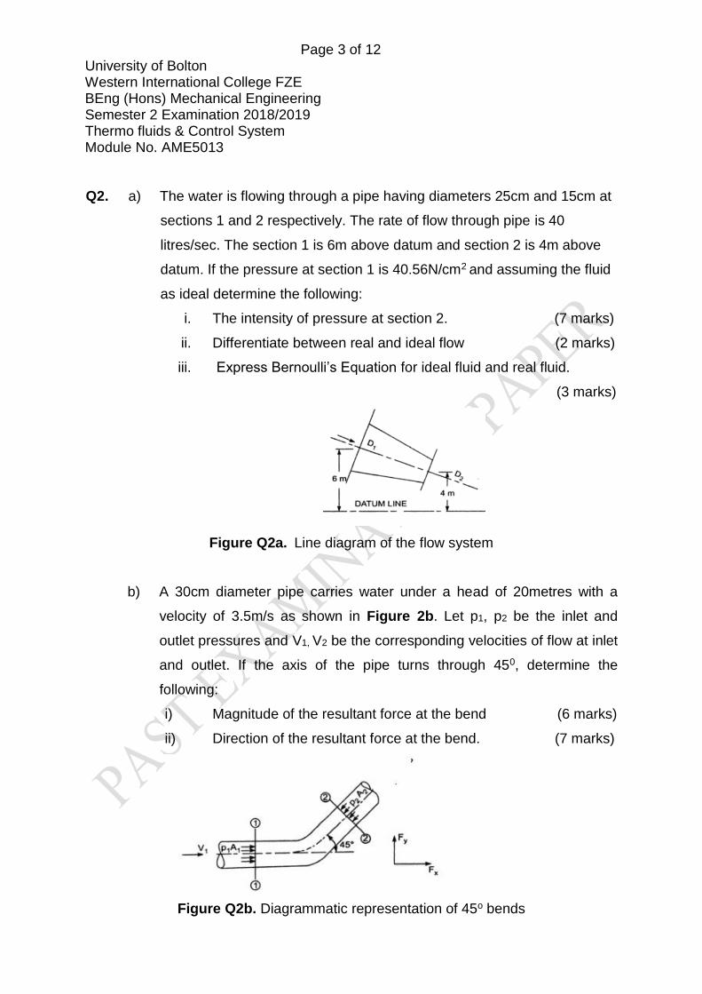
Q2. a) The water is flowing through a pipe having diameters 25cm and 15cm at
sections 1 and 2 respectively. The rate of flow through pipe is 40
litres/sec. The section 1 is 6m above datum and section 2 is 4m above
datum. If the pressure at section 1 is 40.56N/cm2 and assuming the fluid
as ideal determine the following:
i. The intensity of pressure at section 2. (7 marks)
ii. Differentiate between real and ideal flow (2 marks)
iii. Express Bernoulli’s Equation for ideal fluid and real fluid.
(3 marks)
Figure Q2a. Line diagram of the flow system
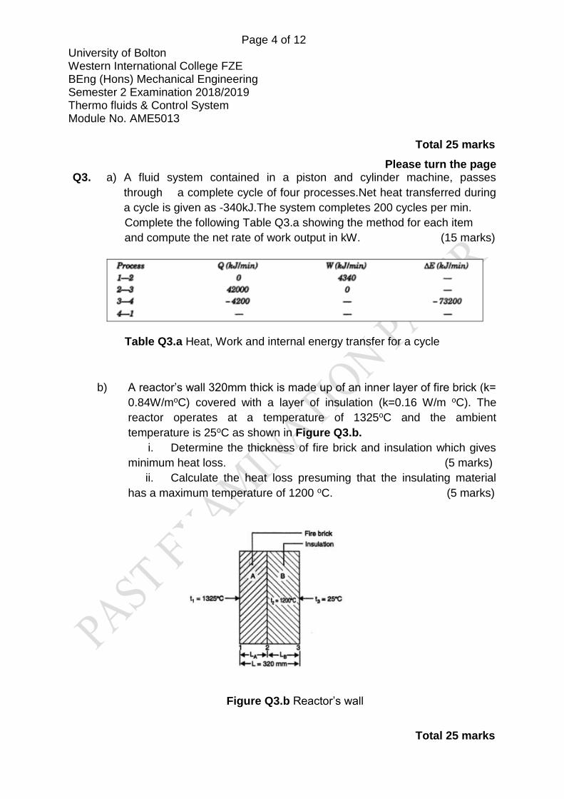
b) A 30cm diameter pipe carries water under a head of 20metres with a
velocity of 3.5m/s as shown in Figure 2b. Let p1, p2 be the inlet and
outlet pressures and V1, V2 be the corresponding velocities of flow at inlet
and outlet. If the axis of the pipe turns through 450, determine the
following:
i) Magnitude of the resultant force at the bend (6 marks)
ii) Direction of the resultant force at the bend. (7 marks)
Figure Q2b. Diagrammatic representation of 45o bends
Page 4 of 12 University of Bolton Western International College FZE BEng (Hons) Mechanical Engineering Semester 2 Examination 2018/2019 Thermo fluids & Control System Module No. AME5013
Total 25 marks
Please turn the page Q3. a) A fluid system contained in a piston and cylinder machine, passes
through a complete cycle of four processes.Net heat transferred during
a cycle is given as -340kJ.The system completes 200 cycles per min.
Complete the following Table Q3.a showing the method for each item
and compute the net rate of work output in kW. (15 marks)
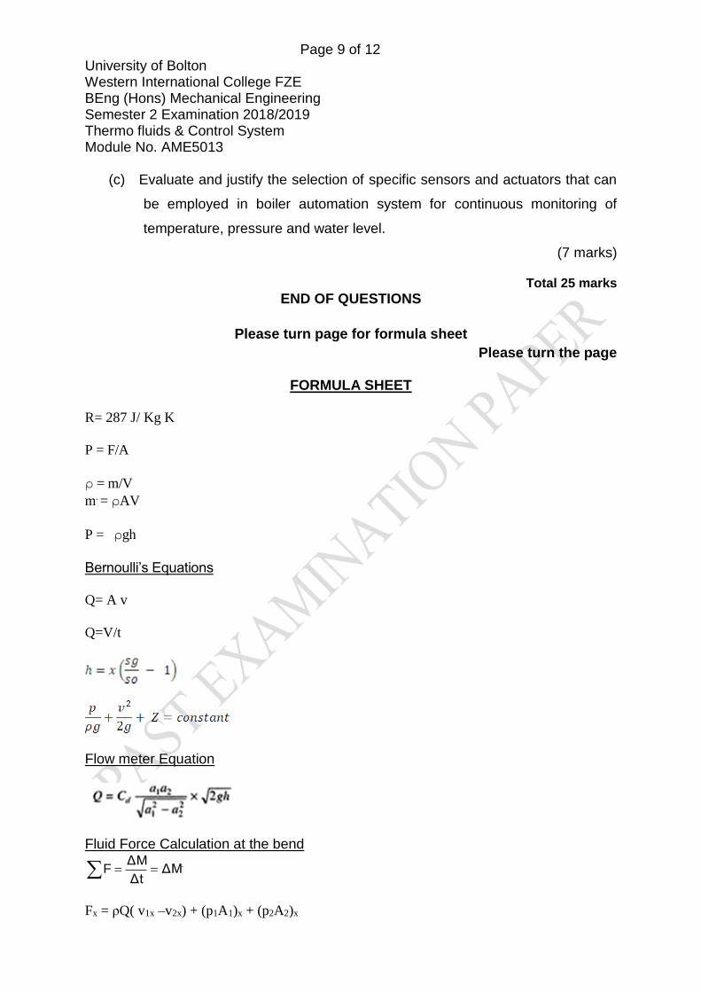
Table Q3.a Heat, Work and internal energy transfer for a cycle
b) A reactor’s wall 320mm thick is made up of an inner layer of fire brick (k=
0.84W/moC) covered with a layer of insulation (k=0.16 W/m oC). The
reactor operates at a temperature of 1325oC and the ambient
temperature is 25oC as shown in Figure Q3.b.
i. Determine the thickness of fire brick and insulation which gives
minimum heat loss. (5 marks)
ii. Calculate the heat loss presuming that the insulating material
has a maximum temperature of 1200 oC. (5 marks)
Figure Q3.b Reactor’s wall
Total 25 marks

Page 5 of 12 University of Bolton Western International College FZE BEng (Hons) Mechanical Engineering Semester 2 Examination 2018/2019 Thermo fluids & Control System Module No. AME5013
Please turn the page
PART B
Q4 a ) For the spring damper and mass system shown in Figure Q4. (a), where
M1 = 2 Kg, K1 = 4 N/m, B1 = 5 Ns/m K3 =5N/m M2 = 3 Kg, K2 = 1 N/m, B2 = 6 Ns/m F(t) = force applied
Figure Q4. (a) Spring damper mass system
(i) Develop differential equations for the system given in Q4.(a) (2 marks)
(ii) Determine the Laplace transforms of the differential equations
obtained from Q4( i) above. (2 marks)
(iii) Determine the transfer function G(s) = X1(s)/F(s), Assume that the
system is subjected to a unit step input and the initial conditions of the
system are zeros (i.e. at time = 0, x, x’, x’’ are all zeros).
(10 marks)
Q4 continued over the page
B1
K1
X1
K2
M2
M1
X2
F(t)
B2
K3

Page 6 of 12 University of Bolton Western International College FZE BEng (Hons) Mechanical Engineering Semester 2 Examination 2018/2019 Thermo fluids & Control System Module No. AME5013
Please turn the page
Q4 continued.
c) Hydraulic actuator shown in Figure Q4.c controls the large displacement
power at the shaft of main piston having an area A(m2). The input power
requirement is provided by the displacement ‘x’, of the valve piston. The
linear motion of the valve piston controls the flow of oil to either side of the
main piston. Derive the transfer function of the hydraulic actuator. Assume
oil to be incompressible and neglect the leakage.
Given P1 = Pressure on the left side of the main piston (N/m2)
P2 = Pressure on the right side of the main piston (N/m2)
q = oil flow in m3/sec
y= output displacement (m)
t =time (sec)
Figure Q4.c Hydraulic actuator system
(11 marks)

Page 7 of 12 University of Bolton Western International College FZE BEng (Hons) Mechanical Engineering Semester 2 Examination 2018/2019 Thermo fluids & Control System Module No. AME5013
Total 25 marks
Please turn the page
Q5 a) Block diagram for a closed loop control system for a thermostatically
controlled air-conditioning system for an automobile is shown in Figure
Q5.(a). Evaluate the time response characteristics of the system.
Figure Q5. (a) Thermostatically controlled air-conditioning system
(10 marks)
(b) Analyse the stability analysis of system for control systems based on
location of roots of characteristic equation in S plane. (6 marks)
(c) A robotic arm has an open loop transfer function for its angular position of
The input of the system is a ramp input changing at the rate 10 degrees
and K has the values 1, 10,100.
i) What will be the steady state errors for different K values when it is
an open loop system.
(4 marks)
ii) What will be the steady state errors for different K values when it is
an closed loop system.
(4 marks)

Page 8 of 12 University of Bolton Western International College FZE BEng (Hons) Mechanical Engineering Semester 2 Examination 2018/2019 Thermo fluids & Control System Module No. AME5013
iii) Comment on the significance of increasing the value of K.
(1 marks)
Total 25 marks
Please turn the page
Q6 a) Large welding robots are widely used in automobile assembly lines.
The welding head is moved to different positions on the automobile
bode, and rapid, accurate response is required. The characteristic
equation for the welding system is
])10([
)(Tsss
KsG
Using Routh-Hurwitz stability criterion analyse the stability of the system. and determine the relation between K and T.
(8 marks)
b) Reduce the following block diagram for an air traffic control systems shown
in Figure Q6. (b) and determine the system transfer function.
Figure Q6. (b) Block diagram for an air traffic control systems
(10 marks)
Page 9 of 12 University of Bolton Western International College FZE BEng (Hons) Mechanical Engineering Semester 2 Examination 2018/2019 Thermo fluids & Control System Module No. AME5013
(c) Evaluate and justify the selection of specific sensors and actuators that can
be employed in boiler automation system for continuous monitoring of
temperature, pressure and water level.
(7 marks)
Total 25 marks
END OF QUESTIONS
Please turn page for formula sheet
Please turn the page
FORMULA SHEET
R= 287 J/ Kg K
P = F/A
ρ = m/V
m. = ρAV
P = ρgh
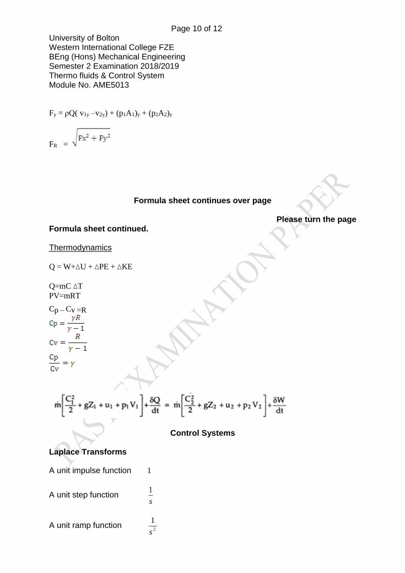
Bernoulli’s Equations
Q= A v
Q=V/t
Flow meter Equation
Fluid Force Calculation at the bend
.ΔMΔt
ΔMF
Fx = ρQ( v1x –v2x) + (p1A1)x + (p2A2)x
Page 10 of 12 University of Bolton Western International College FZE BEng (Hons) Mechanical Engineering Semester 2 Examination 2018/2019 Thermo fluids & Control System Module No. AME5013
Fy = ρQ( v1y –v2y) + (p1A1)y + (p2A2)y
FR =
Formula sheet continues over page
Please turn the page Formula sheet continued.
Thermodynamics
Q = W+ΔU + ΔPE + ΔKE
Q=mC ΔT
PV=mRT
Cp – Cv =R
Control Systems
Laplace Transforms
A unit impulse function 1
A unit step function s
1
A unit ramp function 2
1
s
Page 11 of 12 University of Bolton Western International College FZE BEng (Hons) Mechanical Engineering Semester 2 Examination 2018/2019 Thermo fluids & Control System Module No. AME5013
Formula sheet continues over page
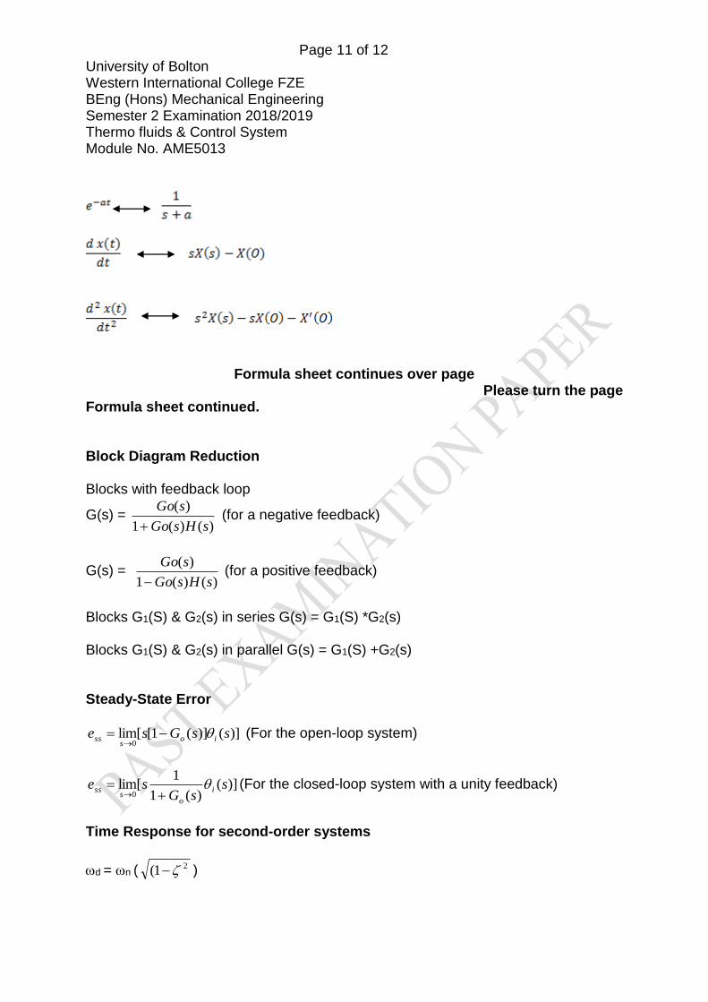
Please turn the page Formula sheet continued. Block Diagram Reduction
Blocks with feedback loop
G(s) = )()(1
)(
sHsGo
sGo
(for a negative feedback)
G(s) = )()(1
)(
sHsGo
sGo
(for a positive feedback)
Blocks G1(S) & G2(s) in series G(s) = G1(S) *G2(s) Blocks G1(S) & G2(s) in parallel G(s) = G1(S) +G2(s) Steady-State Error
)]()](1[[lim0
ssGse ios
ss
(For the open-loop system)
)]()(1
1[lim
0s
sGse i
os
ss
(For the closed-loop system with a unity feedback)
Time Response for second-order systems
d = n (21( )

Page 12 of 12 University of Bolton Western International College FZE BEng (Hons) Mechanical Engineering Semester 2 Examination 2018/2019 Thermo fluids & Control System Module No. AME5013
ᶲ = tan-1(
)1( 2)
tr = ( - ᶲ)/d
tp = /d
n
4= ts
%100))1(
(exp = Mp.2
END OF PAPER