university of birmingham investigating the monotonic
TRANSCRIPT

University of Birmingham
Investigating the monotonic behaviour of hybridtripod suction bucket foundations for offshore windtowers in sandFaizi, Koohyar; Faramarzi, Asaad; Dirar, Samir; Chapman, David
DOI:10.1016/j.apor.2019.05.018
License:Creative Commons: Attribution-NonCommercial-NoDerivs (CC BY-NC-ND)
Document VersionPeer reviewed version
Citation for published version (Harvard):Faizi, K, Faramarzi, A, Dirar, S & Chapman, D 2019, 'Investigating the monotonic behaviour of hybrid tripodsuction bucket foundations for offshore wind towers in sand', Applied Ocean Research, vol. 89, pp. 176-187.https://doi.org/10.1016/j.apor.2019.05.018
Link to publication on Research at Birmingham portal
Publisher Rights Statement:Checked for eligibility: 26/07/2019
General rightsUnless a licence is specified above, all rights (including copyright and moral rights) in this document are retained by the authors and/or thecopyright holders. The express permission of the copyright holder must be obtained for any use of this material other than for purposespermitted by law.
•Users may freely distribute the URL that is used to identify this publication.•Users may download and/or print one copy of the publication from the University of Birmingham research portal for the purpose of privatestudy or non-commercial research.•User may use extracts from the document in line with the concept of ‘fair dealing’ under the Copyright, Designs and Patents Act 1988 (?)•Users may not further distribute the material nor use it for the purposes of commercial gain.
Where a licence is displayed above, please note the terms and conditions of the licence govern your use of this document.
When citing, please reference the published version.
Take down policyWhile the University of Birmingham exercises care and attention in making items available there are rare occasions when an item has beenuploaded in error or has been deemed to be commercially or otherwise sensitive.
If you believe that this is the case for this document, please contact [email protected] providing details and we will remove access tothe work immediately and investigate.
Download date: 19. Mar. 2022

1
Investigating the Monotonic Behaviour of Hybrid Tripod Suction Bucket 1
Foundations for Offshore Wind Towers in Sand 2
Koohyar Faizi1, Asaad Faramarzi2, Samir Dirar3, David Chapman4 3
4
1PhD student, School of Engineering, University of Birmingham, Edgbaston, 5
Birmingham B15 2TT, UK, [email protected] 6
2Assistant Professor, School of Engineering, University of Birmingham, 7
Edgbaston, Birmingham B15 2TT, UK, [email protected] 8
3Associate Professor, School of Engineering, University of Birmingham, 9
Edgbaston, Birmingham B15 2TT, UK, [email protected] 10
4Professor, School of Engineering, University of Birmingham, Edgbaston, 11
Birmingham B15 2TT, UK, [email protected] 12
13
14
2
Abstract: Existing tripod suction bucket foundations, utilised for offshore wind 15
turbines, are required to resist significant lateral loads and overturning moments 16
generated by wind and currents. This paper presents an innovative type of tripod bucket 17
foundation, ‘hybrid tripod bucket foundation’, for foundations of offshore wind 18
turbines, which has the ability to provide a larger overturning capacity compared with 19
conventional tripod buckets. The proposed foundation consists of a conventional tripod 20
bucket combined with three large circular mats attached to each bucket. A series of 21
experiments were conducted on small-scale models of the proposed foundation 22
subjected to overturning moment under 1g conditions in loose sand. Different circular 23
mat diameter sizes with various bucket spacings were considered and the results were 24
compared with conventional tripod bucket foundation. Finite element models of the 25
proposed foundation were developed and validated using experimental results and were 26
used to conduct a parametric study to understand the behaviour of the hybrid tripod 27
bucket foundation. The results showed that there is a significant increase in overturning 28
capacity provided by the novel foundation. The results of this work can significantly 29
improve lowering the costs associated with installation of foundations to support 30
offshore wind turbines. 31
Keywords: Overturning capacity; Hybrid tripod bucket foundations; Sand; Finite 32
element models 33
34
1. Introduction 35
Large horizontal and overturning bearing capacities are generally the 36
key design requirements for offshore shallow foundations [1]. 37
Suction bucket foundations (monopod bucket), also known as a skirted shallow 38
foundations [2], have recently been considered for offshore wind turbines (OWTs) as a 39
cost effective alternative to conventional foundations [3]. As future generations of 40
offshore wind turbines are likely to have taller towers and be located further away from 41

3
the coast, the standard monopod foundations may become uneconomic and tripod 42
suction buckets may be more suitable [4]. 43
Tripod bucket foundations are a standard three-legged structure made of cylindrical 44
bucket foundations. The central steel shaft of the tripod is attached to the turbine tower 45
by tubular space frames. This type of foundation is a popular design due to the smaller 46
diameter buckets, which reduces the probability of structural failure and easier 47
installation, [5] and provides higher bearing capacity for the foundations of OWTs 48
compared with single leg foundations [6, 7]. 49
In case of single bucket foundation, as used in OWTs, the most unfavourable loading 50
condition is large overturning moments due to its low embedment depth [8]. A 51
large penetration to diameter ratio (>1) of the bucket typically has been 52
recommended to obtain satisfactory overturning capacities [9]. Using large buckets is 53
another way to increase capacities. However, as suction buckets are sensitive to 54
structural buckling during the installation process due to the profile characteristics 55
(thin-walled structures) [10, 11], installation of a very large thin wall bucket involves 56
significant risks of buckling. A large diameter suction bucket therefore requires a 57
significant number of stiffeners to prevent skirt buckling during installation. However, 58
any additional stiffeners may adversely impact the installation process [12]. 59
Apart from the shape, the load transfer mechanism from the foundation to the soil is the 60
main difference between the mono and tripod bucket foundations [7]. The large 61
overturning moment can be resisted by a combination of tension and compression on 62
the windward and leeward legs in a tripod foundation, while a single bucket only 63
transfers the loading moment by the individual bucket surface interfaces with 64
surrounding soil [2, 13]. The installation process of the tripod bucket foundation into 65
the seabed is similar to that of the single suction bucket foundation (monopod). After 66
an initial penetration of the bucket into the seabed caused by self-weight, further 67
penetration is achieved by pumping air and water out of the bucket [14-17]. 68

4
The bearing capacity of the single suction bucket foundations has been extensively 69
studied in different soil types [15, 18-20], whereas only a few studies have examined 70
the behaviour of tripod suction bucket foundations under lateral loading [21-23]. 71
Various bucket and soil parameters have a direct influence on the bearing capacity of 72
the tripod bucket foundation, such as the ratio of the bucket spacing to the bucket 73
diameter (S/D), the embedment depth of the bucket (L), the soil–bucket friction angle 74
(δ) and the unit weight (γ) of the soil [21, 24, 25]. 75
Although the increased capacity of tripod buckets has been demonstrated by increasing 76
the spacing of the buckets [22, 24], this will impose significant additional costs to the 77
structure of the space frames, thereby reducing the cost-effectiveness of tripod 78
foundations. This paper proposes a novel tripod foundation taking advantage of 79
combining tripods with circular mats as additional supporting structural elements. 80
Hereafter, this is referred to as a hybrid tripod bucket foundation. The hybrid tripod 81
bucket foundation aims to provide additional horizontal and moment capacity by 82
optimising the bucket spacing and consequently minimise the construction and 83
installation costs associated with large diameter skirted foundations. 84
The hybrid foundation concept has been considered in past studies for OWTs, for 85
example these can be a combination of single suction buckets (Fig. 1a), multiple suction 86
buckets [26-28] (Fig. 1b) or mono-pile foundations (Fig. 1c) [29, 30] fitted on a mat 87
foundation, in which the mat contributes to enhancing the load capacity. A hybrid 88
single bucket foundation, which is a combination of a circular mat and a suction bucket, 89
was shown to provide a higher bearing capacity compared to a conventional caisson in a 90
study by [31]. However, the combination of a circular mat foundation and a 91
conventional tripod bucket foundation to improve the overturning capacity has not been 92
considered previously. 93
This study aimed to investigate the influence of including large mats to the tripod 94
suction bucket in loose sand subjected to horizontal loading by means of numerical and 95
experimental modelling. 96

5
(a) (c) 97
98
(b) 99
Fig. 1. Some proposed hybrid foundations concepts from previous research studies, (a) a 100 modified suction bucket, (b) a skirted mat with suction buckets, (c) a hybrid mono-pile 101
foundation. 102
103
2. Methodology 104
The proposed hybrid foundation consists of three single bucket foundations combined 105
with three large circular mats attached to each bucket foundation. The general concept 106
is shown in Fig. 2. In the conventional tripod bucket foundation, the bearing capacity is 107
provided by three rigidly connected bucket foundations, while in this proposed hybrid 108
foundation, the resistance is offered by a combination of the buckets and the circular 109
mats. In the proposed hybrid foundation the circular mats are in complete contact with 110
the soil surface providing greater resistance against the overturning moments. 111
6
112
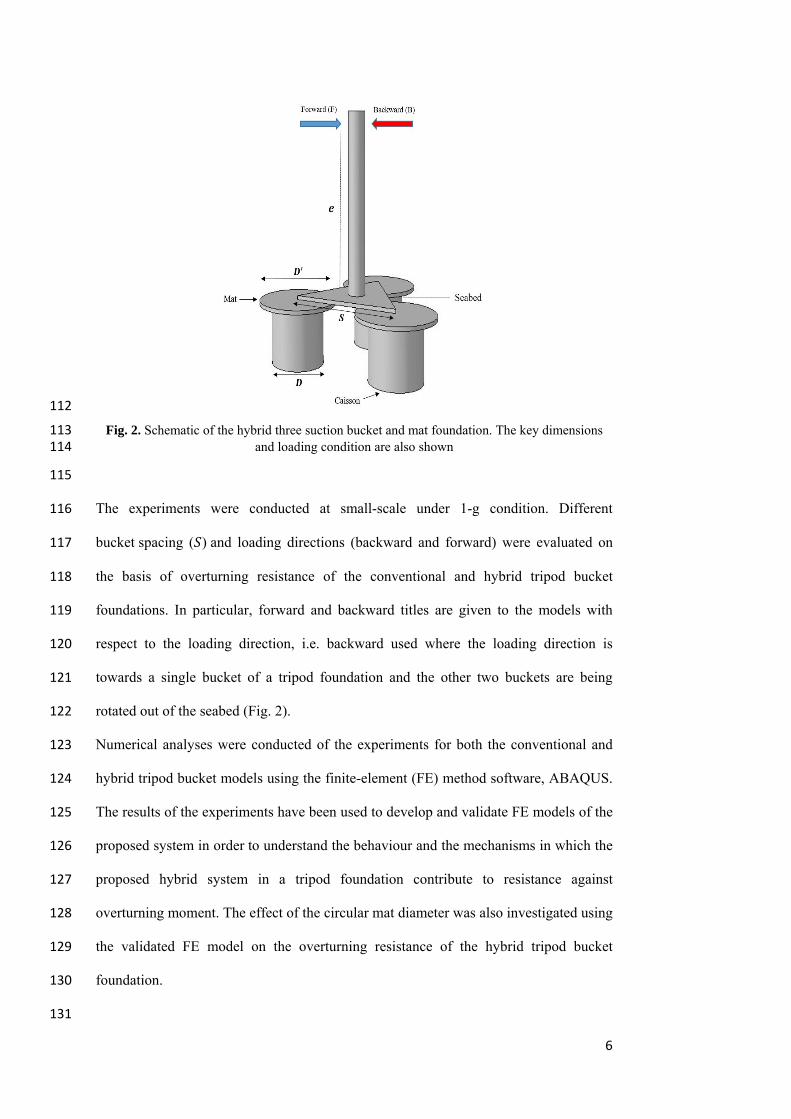
Fig. 2. Schematic of the hybrid three suction bucket and mat foundation. The key dimensions 113 and loading condition are also shown 114
115
The experiments were conducted at small-scale under 1-g condition. Different 116
bucket spacing ( ) and loading directions (backward and forward) were evaluated on 117
the basis of overturning resistance of the conventional and hybrid tripod bucket 118
foundations. In particular, forward and backward titles are given to the models with 119
respect to the loading direction, i.e. backward used where the loading direction is 120
towards a single bucket of a tripod foundation and the other two buckets are being 121
rotated out of the seabed (Fig. 2). 122
Numerical analyses were conducted of the experiments for both the conventional and 123
hybrid tripod bucket models using the finite-element (FE) method software, ABAQUS. 124
The results of the experiments have been used to develop and validate FE models of the 125
proposed system in order to understand the behaviour and the mechanisms in which the 126
proposed hybrid system in a tripod foundation contribute to resistance against 127
overturning moment. The effect of the circular mat diameter was also investigated using 128
the validated FE model on the overturning resistance of the hybrid tripod bucket 129
foundation. 130
131

7
132
3. Experimental Procedure 133
3.1 Materials and model preparation 134
The prototype was scaled down to 1/100, and a bucket embedment depth ratio / of 135
1 and a skirt width to bucket diameter ratio ( / ) = 0.02, were considered. The distance 136
between the buckets is expressed by the spacing ratio / , where is the axial distance 137
between the circular buckets and is their diameter (Fig.1). Experiments were 138
performed using various normalised spacings, / , ranging from 1.13 to 3.13. 139
The three conventional buckets with the external diameter and embedment depth 140
( ) of 75 mm were connected with an adjustable plate. The caisson specimens 141
were fabricated from a smooth stainless steel tube with a wall thickness ( ) of 1.2 mm. 142
The adjustable mechanism consisted of an equilateral triangular plastic plate (200 mm 143
long and 5 mm thick) with three linear holes in each angle. The three buckets were 144
connected to the adjustable mechanism by screws. By adjusting the distance between 145
the buckets, three different configurations could be created (more details are provided 146
in section 5.2). Three circular mats with a diameter of 120 mm, made of plastic, were 147
used to replace the conventional suction bucket caps and help to create the hybrid tripod 148
foundation (Fig. 3). 149
150
8
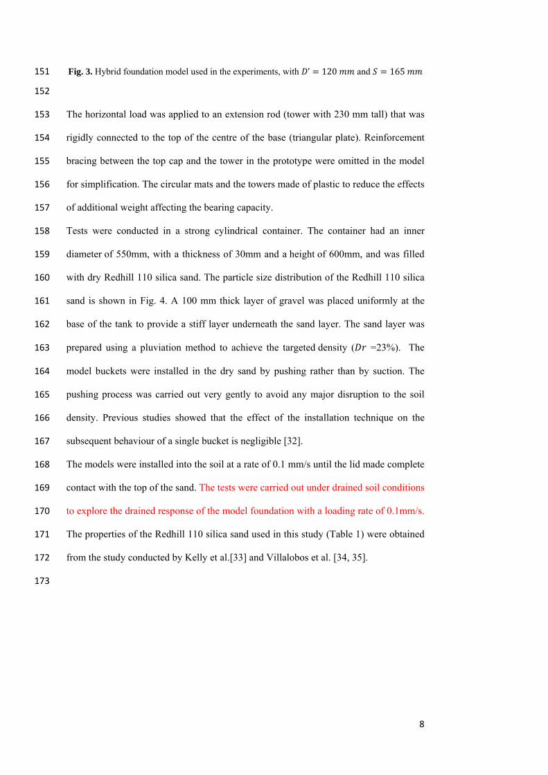
Fig. 3. Hybrid foundation model used in the experiments, with ’ 120 and 165 151
152
The horizontal load was applied to an extension rod (tower with 230 mm tall) that was 153
rigidly connected to the top of the centre of the base (triangular plate). Reinforcement 154
bracing between the top cap and the tower in the prototype were omitted in the model 155
for simplification. The circular mats and the towers made of plastic to reduce the effects 156
of additional weight affecting the bearing capacity. 157
Tests were conducted in a strong cylindrical container. The container had an inner 158
diameter of 550mm, with a thickness of 30mm and a height of 600mm, and was filled 159
with dry Redhill 110 silica sand. The particle size distribution of the Redhill 110 silica 160
sand is shown in Fig. 4. A 100 mm thick layer of gravel was placed uniformly at the 161
base of the tank to provide a stiff layer underneath the sand layer. The sand layer was 162
prepared using a pluviation method to achieve the targeted density ( =23%). The 163
model buckets were installed in the dry sand by pushing rather than by suction. The 164
pushing process was carried out very gently to avoid any major disruption to the soil 165
density. Previous studies showed that the effect of the installation technique on the 166
subsequent behaviour of a single bucket is negligible [32]. 167
The models were installed into the soil at a rate of 0.1 mm/s until the lid made complete 168
contact with the top of the sand. The tests were carried out under drained soil conditions 169
to explore the drained response of the model foundation with a loading rate of 0.1mm/s. 170
The properties of the Redhill 110 silica sand used in this study (Table 1) were obtained 171
from the study conducted by Kelly et al.[33] and Villalobos et al. [34, 35]. 172
173

9
174
175
Fig. 4. Particle size distribution curves for Redhill 110 176 177
Table 1. Physical properties of sand used in the model tests, Redhill 110 178
Properties Value
, , , (mm) 0.08, 0.10, 0.12, 0.13
Coefficients of uniformity, and curvature 1.63, 0.96
Specific gravity, 2.65
Minimum dry density, (kN/m3 ) 12.76
Maximum dry density, (kN/m3 ) 16.80
Angle of friction of the soil,∅ 36º
Permeability (m/s) 3.8 10
179
180
3.2 Test procedure 181
For all the models, to create a moment, , a horizontal load ’was applied using an 182
electric actuator at a certain height (230 mm) above the cap of the tripod bucket. An 183
eccentricity ratio (i.e. / ’ )) equal to 2.9 was used in this study, which corresponds 184
to tall wind turbine towers (>100 m). A load cell was attached to the actuator to 185

10
measure the applied force. The rotation of the foundation was recorded using an 186
inclinometer sensor placed on the top of the tower (as shown in Fig. 5). 187
Fig. 5(b) shows the plan view of the experimental set up and the loading system. As 188
illustrated, the model tripod foundations were placed in the middle of the model 189
container. The model tests were carried out in the central part of the container to ensure 190
minimal influence due to the wall boundary conditions. 191
All the information related to the models and tests are summarised in Table 2; in this 192
table the conventional tripod bucket foundations and the hybrid tripod bucket 193
foundations are denoted C and H, respectively. The results from the experiments are 194
presented in section 5, where they have been used to validate the results of the 195
numerical models. 196
197
(a) 198

11
199 (b) 200
201
202 (c) 203
204 Fig. 5. Testing system with loading actuator and tripod model (a) overview of the experimental 205 setup; (b) schematic of elevation view; (c) schematic of setup plan view 206 207
12
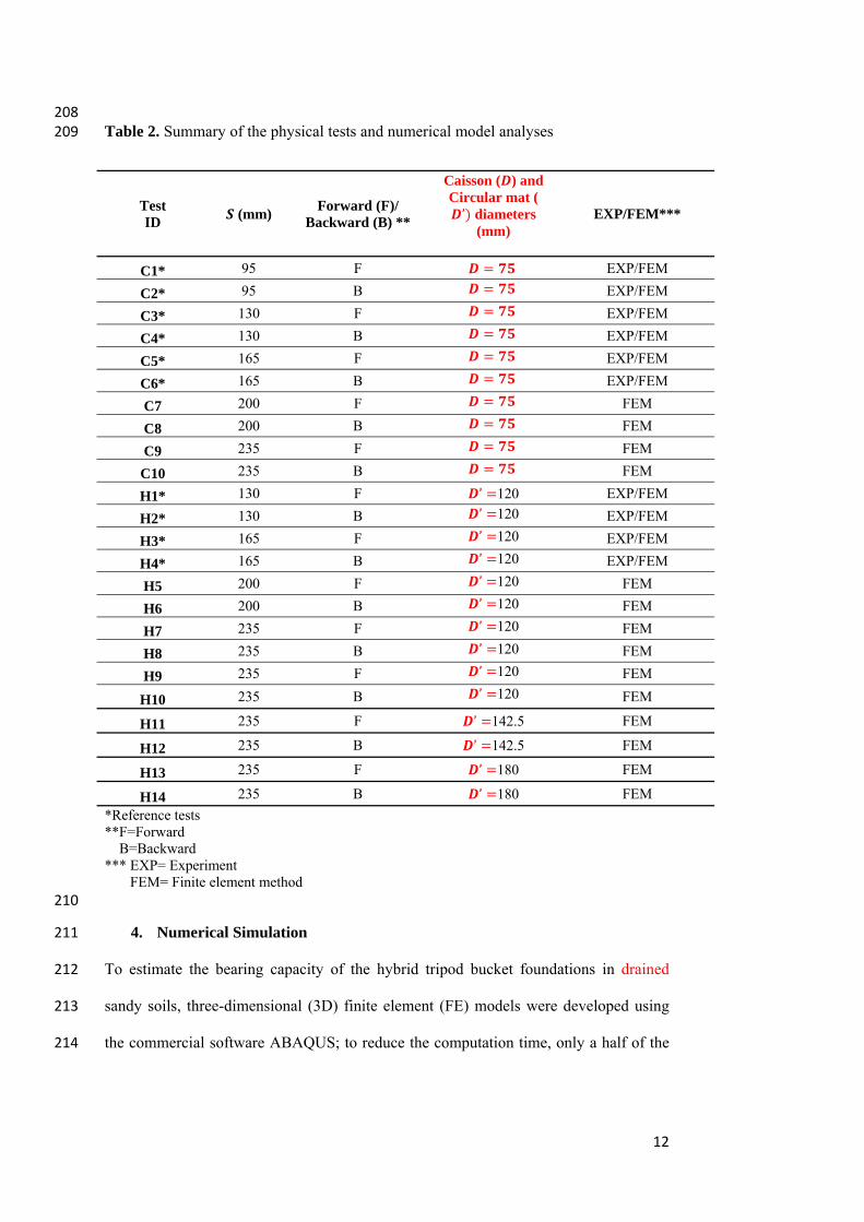
208 Table 2. Summary of the physical tests and numerical model analyses 209
Test ID
(mm) Forward (F)/
Backward (B) **
Caisson ( ) and Circular mat (’ diameters
(mm)
EXP/FEM***
C1* 95 F EXP/FEM
C2* 95 B EXP/FEM
C3* 130 F EXP/FEM
C4* 130 B EXP/FEM
C5* 165 F EXP/FEM
C6* 165 B EXP/FEM
C7 200 F FEM
C8 200 B FEM
C9 235 F FEM
C10 235 B FEM
H1* 130 F ’ 120 EXP/FEM
H2* 130 B ’ 120 EXP/FEM
H3* 165 F ’ 120 EXP/FEM
H4* 165 B ’ 120 EXP/FEM
H5 200 F ’ 120 FEM
H6 200 B ’ 120 FEM
H7 235 F ’ 120 FEM
H8 235 B ’ 120 FEM
H9 235 F ’ 120 FEM
H10 235 B ’ 120 FEM
H11 235 F ’ 142.5 FEM
H12 235 B ’ 142.5 FEM
H13 235 F ’ 180 FEM
H14 235 B ’ 180 FEM
*Reference tests **F=Forward B=Backward *** EXP= Experiment FEM= Finite element method 210
4. Numerical Simulation 211
To estimate the bearing capacity of the hybrid tripod bucket foundations in drained 212
sandy soils, three-dimensional (3D) finite element (FE) models were developed using 213
the commercial software ABAQUS; to reduce the computation time, only a half of the 214
13
foundation and the ground were modelled taking advantage of the symmetry within the 215
problem. 216
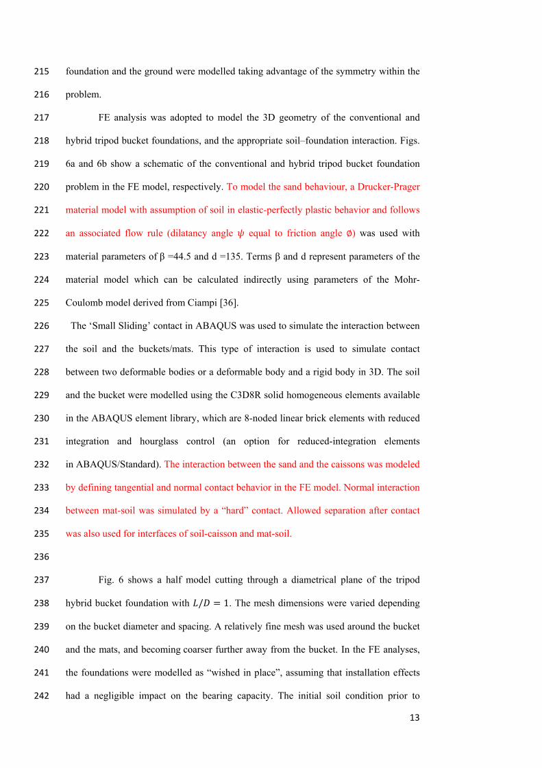
FE analysis was adopted to model the 3D geometry of the conventional and 217
hybrid tripod bucket foundations, and the appropriate soil–foundation interaction. Figs. 218
6a and 6b show a schematic of the conventional and hybrid tripod bucket foundation 219
problem in the FE model, respectively. To model the sand behaviour, a Drucker-Prager 220
material model with assumption of soil in elastic-perfectly plastic behavior and follows 221
an associated flow rule (dilatancy angle equal to friction angle ∅) was used with 222
material parameters of β =44.5 and d =135. Terms β and d represent parameters of the 223
material model which can be calculated indirectly using parameters of the Mohr-224
Coulomb model derived from Ciampi [36]. 225
The ‘Small Sliding’ contact in ABAQUS was used to simulate the interaction between 226
the soil and the buckets/mats. This type of interaction is used to simulate contact 227
between two deformable bodies or a deformable body and a rigid body in 3D. The soil 228
and the bucket were modelled using the C3D8R solid homogeneous elements available 229
in the ABAQUS element library, which are 8-noded linear brick elements with reduced 230
integration and hourglass control (an option for reduced-integration elements 231
in ABAQUS/Standard). The interaction between the sand and the caissons was modeled 232
by defining tangential and normal contact behavior in the FE model. Normal interaction 233
between mat-soil was simulated by a “hard” contact. Allowed separation after contact 234
was also used for interfaces of soil-caisson and mat-soil. 235
236
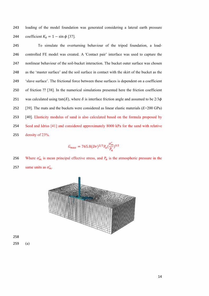
Fig. 6 shows a half model cutting through a diametrical plane of the tripod 237
hybrid bucket foundation with / 1. The mesh dimensions were varied depending 238
on the bucket diameter and spacing. A relatively fine mesh was used around the bucket 239
and the mats, and becoming coarser further away from the bucket. In the FE analyses, 240
the foundations were modelled as “wished in place”, assuming that installation effects 241
had a negligible impact on the bearing capacity. The initial soil condition prior to 242
14
loading of the model foundation was generated considering a lateral earth pressure 243
coefficient 1 sin [37]. 244
To simulate the overturning behaviour of the tripod foundation, a load-245
controlled FE model was created. A 'Contact pair’ interface was used to capture the 246
nonlinear behaviour of the soil-bucket interaction. The bucket outer surface was chosen 247
as the ‘master surface’ and the soil surface in contact with the skirt of the bucket as the 248
‘slave surface’. The frictional force between these surfaces is dependent on a coefficient 249
of friction ?? [38]. In the numerical simulations presented here the friction coefficient 250
was calculated using tan , where is interface friction angle and assumed to be 2/3 251
[39]. The mats and the buckets were considered as linear elastic materials (E=200 GPa) 252
[40]. Elasticity modulus of sand is also calculated based on the formula proposed by 253
Seed and Idriss [41] and considered approximately 8000 kPa for the sand with relative 254
density of 23%. 255
765.8 / .
Where is mean principal effective stress, and is the atmospheric pressure in the 256
same units as . 257
258
(a) 259
15
260
(b) 261
Fig. 6. Finite element model of the a) conventional and b) hybrid tripod bucket foundations used 262 to analyse the laterally loading behaviour 263
264
Based on the results of the FE analyses, the moment-rotation curves ( of 265
the foundations were constructed to obtain the ultimate overturning capacity. The 266
curves are inherently nonlinear being controlled by the “elastic” stiffness at small 267
rotations and the moment capacity of the foundation at larger rotations. The ultimate 268
moment capacity of the foundation has been defined as the moment corresponding to 269
the yield point. To define the yield point, the method described by Villalobos [32] was 270
used. In this method, straight lines were fitted to the initial stiff elastic section and the 271
plastic section, as shown in Fig. 7. A horizontal line is then drawn from the intersection 272
point of the two fitted lines to the load-rotation angle curve. This line will be extended 273
until it cuts the moment-rotation curve, the intersection between the horizontal line and 274
the curve was defined as the ultimate moment, denoted as . 275

16
276
Fig. 7. Tangent intersection method for determining the yield point and hence the ultimate 277 bearing capacity of the foundation 278
279
5. Results and Analysis 280
The experiments using the convention foundations in the C1-C6 series (as listed 281
in Table 2) were conducted under identical test conditions, including soil density, 282
bucket aspect ratio ( / =1) and type of loading, although bucket spacing ( ) was 283
varied from 90 mm to 165mm (see Table 2). The experiments H1-H4 were carried out 284
on the hybrid tripod bucket foundations with circular mats of diameter 1.6 times larger 285
than the bucket diameter ( ’=120 mm) in the same sequence and under the same 286
experimental conditions as the C1-C6 experiments. The remaining models in Table 2 287
(i.e. C7-C10, and H5-H14) refer to FE models that were created to identify the effect of 288
different spacing and different mat size beyond those used in the experiments. All the 289
experiments assigned odd numbers within the test IDs (e.g. C1, C3, H1, H3) are for 290
models subjected to a forward loading direction, while the even numbers (e.g. C2, C4, 291
H2, H4) are for the models loaded in the backward direction. 292
The tripod foundation resists the overturning moment with the reaction generated in the 293
windward and leeward bucket foundations acting in tension and compression, 294
respectively [42, 43]. Based on the deformation mechanisms, observed in Fig. 8, the 295

296
297
298
299
300
301
302
303
304
305
306
307
308
309
310
311
312
overturn
windwar
EXP con
FEM hyb
5.1
Initially,
conventi
perform
eccentric
failure w
on the d
(a)
(b)
ning moment
rd and leewa
Fig. 8. Failure
nventional foun
brid foundatio
The effect
conventiona
, the impact
ional and hy
ed by apply
city from the
was reached.
direction of
t is resisted
ard in both co
e mechanism
ndation, (b) F
on
of bucket
al foundatio
of the buck
ybrid tripod b
ying a mono
e top of the
The numeri
the load and
by a combi
onventional a
due to an ove
EM conventio
spacing an
on (Finite El
ket spacing o
bucket found
tonic horizo
foundations
cal and expe
d bucket spa
ination of te
and hybrid tr
erturning mom
onal foundatio
d loading d
lement and E
on the overtu
dations are ex
ontal load at
( = 230 mm
erimental res
acing of bot
(c)
(d)
ension and c
ripod founda
ment in the forw
on, (c) EXP hy
direction on
Experiment
urning mom
xamined. The
the top of
m). This load
sults have be
th the conve
ompression
ations.
ward direction
ybrid foundati
n the capac
al Modellin
ent capacity
e experiment
the tower, w
d was applie
en compared
ntional and
17
on the
n, (a)
tion, (d)
city of
ng)
y of the
ts were
with an
ed until
d based
hybrid

18
tripod foundations. The comparison demonstrated that the numerical simulations 313
provide very close results (<10% average error) to the experimental data (Figs. 9-13). 314
As can be seen in Figures 9-13, the bearing capacity of the conventional tripod due to 315
an overturning moment is higher when the foundations are subjected to the backward 316
loading direction, i.e. the foundation with =95 mm maintained an almost 18% higher 317
capacity under backward loading compared with the experiments loaded in the forward 318
direction (Fig. 9). 319
The horizontal resistance of a tripod depends on the loading direction due to the 320
asymmetry of the foundations [44]. Previous studies have revealed that the capacity of 321
tripod systems is primarily governed by the pull-out capacity of the windward bucket 322
[43, 44]. It should also be noted, however, that the capacity of single suction buckets 323
under pull-out is lower than in compression [45]. Hence, the number of windward 324
buckets in the tripod foundation could control the overall capacity. Accordingly, the 325
two windward buckets provide a higher capacity compared with the scenario where two 326
buckets are in compression. Therefore, the most critical loading condition for tripods is 327
when the horizontal loading is imposed in the forward direction (F), i.e. where one 328
bucket of the tripod resists pull-out load, as shown in Fig. 8. This observation for 329
conventional tripod foundations is similar to that reported by Kim et al. [44]. 330
331
332
333

19
334
Fig. 9. Moment-rotation plot for the conventional foundation system with a spacing dimension 335 of 95 mm (EXP and FEM) 336
337
5.2 The effect of the hybrid system on the capacity improvement of tripod 338
bucket foundations 339
The impact of using a hybrid system on the overturning capacity of a tripod bucket 340
foundation is presented by means of a series of laboratory tests and numerical 341
modelling. Comparing Figs. 10 and 11, it is clear that there is a significant increase in 342
the overturning capacity provided by the hybrid tripod foundation. The test results show 343
that the overturning capacity of the tripod bucket foundation, under the forward loading 344
direction, was increased by approximately 47% and 45%, for bucket spacings of 130 345
mm and 165 mm, respectively (Figs. 10 and 11). For the same spacing, the ultimate 346
overturning bearing capacity increased by approximately 43% and 38%, for the models 347
under the backward loading direction. 348
Based on the results, it is evident that attaching circular mats can provide additional 349
resistance compared to the original tripod foundation. The contact surfaces between the 350
circular mats and the seabed and the development of bearing stress beneath the mats 351
provides a larger restoring moment to withstand the rotation. Moreover, the circular 352

20
mats induce additional vertical stresses in the soil beneath the foundation, thereby 353
helping to increase the shear resistance of the soil and further resisting rotation. 354
355
356
Fig. 10. Moment-rotation plot for conventional and hybrid foundation systems with a bucket 357 spacing of 130 mm (EXP and FEM) 358
359
360

21
Fig. 11. Moment-rotation plot for conventional and hybrid foundation systems with a bucket 361 spacing of 165 mm (EXP and FEM) 362
363
5.3 The effect of bucket spacing size and mat diameter on the improvement of 364
capacity of hybrid system (FEM) 365
The results from the three-dimensional finite element analyses (FEM) for the 366
two tripod foundation models (with and without circular mats) are presented in Figs. 367
12-14 in terms of the moment and rotation with varying circular mat diameters and 368
bucket spacing. 369
A series of numerical models (C7, C8, H5 and H6) were performed in which 370
the mat diameter was kept the same as those used in the previous models (371
120 while the bucket spacing was changed to 200 mm in order to evaluate 372
the effect of higher spacing on the overturning moment resistance of the conventional 373
and hybrid tripod foundations. 374
The moment-rotation ( curves for the conventional and hybrid tripod 375
models with diameter 120 and spacing S 200 mm installed in loose sand 376
with relative density of =23% are presented in Fig. 12. The results from the FEM 377
indicated that the mats used in the proposed foundation have a significant impact on 378
improving the overturning capacity. The mat aids the resisting force against the external 379
load by extending the contact area. The results also showed that the overturning 380
capacity of the tripod bucket foundation was increased by approximately 53%, and 47% 381
for the hybrid bucket foundation, under F and B load conditions. 382
383

22
384
Fig. 12. Comparison of the moment-rotation plots for conventional and hybrid foundations with 385 a bucket spacing of 200 mm (FEM) 386
387
A FEM was also developed to investigate the effects of the mat diameter to 388
improve the capacity of the hybrid tripod bucket foundations. The models C9, C10, H7, 389
H8, H11, H12, H13 and H14 were selected with mat sizes both smaller and larger than 390
those used in the reference models ( 120 ). When equals 3.13, the ultimate 391
overturning bearing capacity increased by approximately 18%, 36% and 80% for hybrid 392
tripod models under a backward loading system with mat diameter ratios equal to 393
1.3, 1.9 and 2.4, respectively (see Fig. 13). However, it is worth noting that combining 394
circular mats with the buckets results in a slightly better overturning capacity under 395
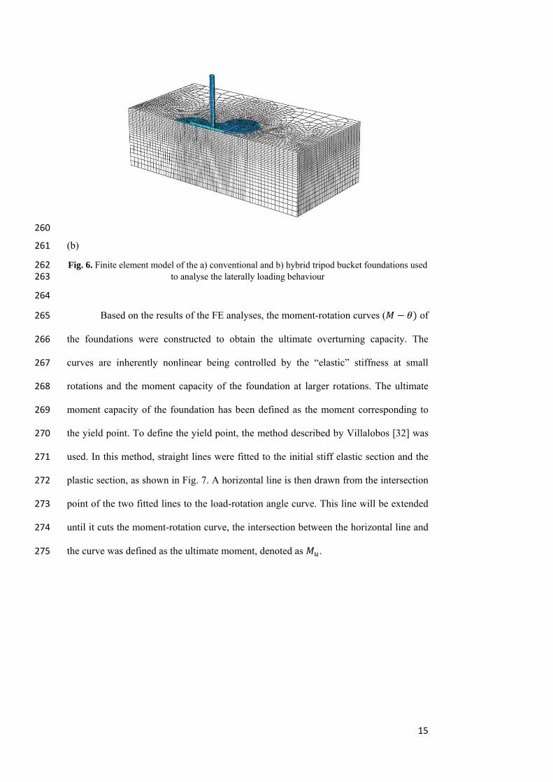
forward loading compared with backward loading. When equals 3.13, the ultimate 396
overturning capacity increased by approximately 25%, 50%, and 100% for hybrid 397
tripod models with mat diameter ratios of approximately 1.3, 1.9, and 2.4, 398
respectively (Fig.14). Given the most unstable loading scenario is when the horizontal 399
loading is imposed in the forward direction (F) [44], two circular mats attached to the 400

23
two buckets at the leeward side provides higher resistance against overturning 401
moments. This resistance corresponds to the larger contact surface areas between the 402
circular mats, attached to the leeward buckets, and the seabed during the loading. In the 403
forward direction, only the mat attached to the bucket at the leeward resists the 404
horizontal load because the two other mats on the windward side are lifted from the soil 405
surface when the whole foundation is rotating. 406
407
408
Fig. 13. Comparison of the moment-rotation plots for conventional and hybrid foundations with 409 a bucket spacing of 235 mm and varying circular mat sizes, due to a backward loading direction 410 (FEM) 411
412
413
24
414
Fig. 14. Comparison of the moment-rotation plots for conventional and hybrid foundations with 415 a bucket spacing of 235 mm and varying circular mat sizes, due to a forward loading direction 416 (FEM) 417
418
419
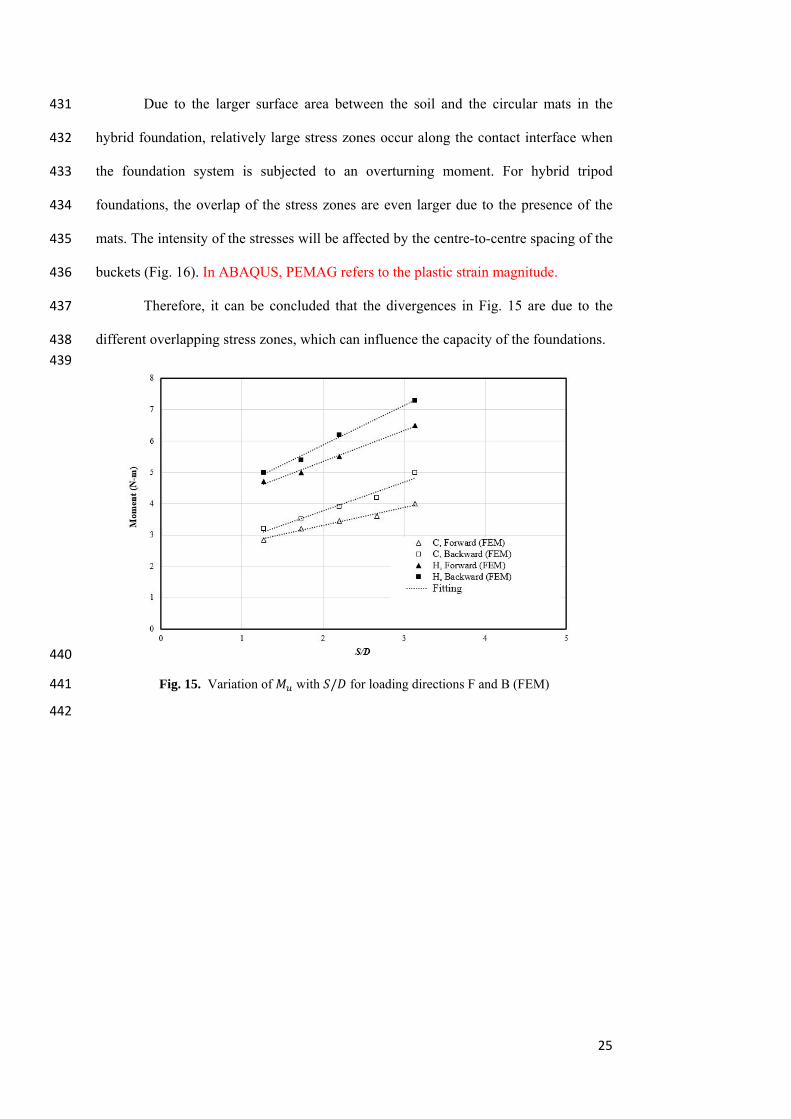
Fig. 15 illustrates the variation in with the normalized footing spacing / 420
for the conventional and hybrid tripod foundations under the forward and backward 421
loading directions. The hybrid models are enhanced with the circular mat diameter of 422
120 mm. As expected, increases significantly as / increases, which is due to the 423
increase in the lever arm length with an increase in / . The bearing capacity of tripod 424
bucket foundations is influenced by the spacing between the buckets because of their 425
mutual interaction [21]. 426
In general, the interactions in a hybrid tripod bucket foundation can be 427
classified into two categories: the interaction between buckets (bucket–soil–bucket) and 428
the interaction between mat and bucket (mat–soil–bucket). A close spacing between 429
individual caissons in a tripod caisson results in overlapping stress zones. 430
25
Due to the larger surface area between the soil and the circular mats in the 431
hybrid foundation, relatively large stress zones occur along the contact interface when 432
the foundation system is subjected to an overturning moment. For hybrid tripod 433
foundations, the overlap of the stress zones are even larger due to the presence of the 434
mats. The intensity of the stresses will be affected by the centre-to-centre spacing of the 435
buckets (Fig. 16). In ABAQUS, PEMAG refers to the plastic strain magnitude. 436
Therefore, it can be concluded that the divergences in Fig. 15 are due to the 437
different overlapping stress zones, which can influence the capacity of the foundations. 438
439
440
Fig. 15. Variation of with / for loading directions F and B (FEM) 441
442

26
(a)
(b)
443
Fig. 16. Plan view of the shear zone formation in hybrid tripod foundations from the FEM 444 results, (a) H2, (b) H10. 445
446
5.4 Large-Scale Numerical Modelling 447
5.4.1 Validation of finite element modelling against large-scale field trials 448
To understand the large-scale behaviour of the proposed tripod foundation, a series of 449
FE models were developed to study their behaviour in field conditions. Initially, 450
validation against two large-scale field trials on single suction caisson foundations 451
available from literature were carried out to ensure the accuracy of our FE modelling. 452
The FE models were then developed to predict the overturning capacity of the 453
conventional and hybrid tripod foundations. 454
Of the available data in literature, two field tests were chosen to validate our FE 455
models. The field tests were originally reported by Houlsby and Byrne [46] and 456
Houlsby et al. [4] at the Sandy Haven and Frederikshavn test sites, respectively. The 457
parameters used in the FEM simulations are given in Table 3. Both sites comprised of 458
predominantly sandy soil. In the FE, the loading was simulated as drained to replicate 459
the site condition. 460

27
The suction caisson at the Sandy Haven site had a diameter of 4 m and a skirt 461
length of 2.5 m, and it was installed in medium to dense sand. The foundation was 462
subjected to a constant vertical load of 100 kN. The horizontal load test was then 463
conducted at a loading point height of 14.5 m above the ground surface. The suction 464
caisson tested at the Frederikshavn site, which had a diameter of 2 m and a skirt length 465
of 2 m, was installed in dense sand. The foundation was subjected to horizontal loading 466
at a height of 17.4 m above the ground surface under a constant vertical load of 37.3 467
kN. Figures 17a, and 17b show that load-displacement curves obtained from the FE 468
analysis agreed well with those measured in the field tests and the centrifuge test. In the 469
numerical simulations presented here the friction coefficient was calculated using 470
tan , where is interface friction angle and assumed with the well-known 471
assumption of =2/3 [47]. The elastic modulus of the sands ( ) is estimated based on 472
the shear modulus G proposed by Seed and Idriss [41]. An average penetration depth 473
was considered for estimation of equivalent modulus of elasticity. The modulus of 474
elasticity(E), 210GPa and Poisson’sratio (ν), 0.3 were used as the steel properties [48]. 475
476
TABLE 3. Detailed reference studies for validation of FEM modelling 477
Case study Diameter
Length
Load
eccentricity
Aspect
ratio
/
Effective
unit weight
( ’
Internal friction
angle
(∅
Frederikshavn [46] 2m 2m 17.4m 1 9 37-38
Sandy Haven [4] 4m 2.5m 14.5m 0.625 8.5 34
478

28
479
480
(a) 481
482
(b) 483
Fig. 17. Comparison of the numerical modelling and the field test results a) Frederikshavn, b) 484 Sandy haven 485
486
487
29
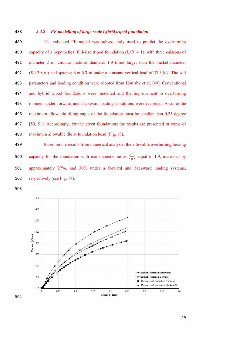
5.4.2 FE modelling of large-scale hybrid tripod foundation 488
The validated FE model was subsequently used to predict the overturning 489
capacity of a hypothetical full-size tripod foundation ( / 1), with three caissons of 490
diameter 2 m, circular mats of diameter 1.9 times larger than the bucket diameter 491
( ’=3.8 m) and spacing S 6.3munder a constant vertical load of 37.3 kN. The soil 492
parameters and loading condition were adopted from Houlsby et al. [49]. Conventional 493
and hybrid tripod foundations were modelled and the improvement in overturning 494
moment under forward and backward loading conditions were recorded. Assume the 495
maximum allowable tilting angle of the foundation must be smaller than 0.25 degree 496
[50, 51]. Accordingly, for the given foundations the results are presented in terms of 497
maximum allowable tile at foundation head (Fig. 18). 498
Based on the results from numerical analysis, the allowable overturning bearing 499
capacity for the foundation with mat diameter ratios equal to 1.9, increased by 500
approximately 27%, and 30% under a forward and backward loading systems, 501
respectively (see Fig. 18). 502
503
504

30
Fig. 18. Comparison of the moment-rotation plots for the conventional and hybrid foundations 505 with a bucket spacing of 6.3 m and circular mat size of 3.8 m, due to a forward and backward 506 loading direction (FEM) 507
508
It is clear from the experiments and the FEM studies that there are benefits of using 509
circular mats in combination with buckets to enhance the overall capacity of tripod 510
suction bucket foundations. Making an effort to reduce the high costs associated with 511
manufacturing and installing of a conventional tripod foundation (with large diameter) 512
at large spacing, the hybrid foundation can provide cost effective operation for offshore 513
wind turbines. 514
Since the main goal of this paper was to evaluate the bearing capacity improvement of 515
the proposed foundation, the structural aspects were beyond the scope of this study and 516
were not evaluated; however, the analysis must account for the structural behaviour of 517
the proposed foundation in the future design. 518
In the present study, drained conditions have been assumed for the experiments, 519
however the models should also be examined under partially drained or undrained 520
conditions. Tripod bucket foundations may be installed in a variety of soils, therefore 521
the effectiveness of mats for tripod bucket foundations installed in different soil types, 522
with different sand density, should also be investigated. Further studies are also 523
necessary in order to investigate the behaviour of the hybrid tripod bucket foundations 524
under combined loads. 525
526
527
6. Conclusions 528
In this study a novel hybrid tripod bucket foundation has been proposed with the 529
intention of improving the overturning capacity of bucket foundations typically 530
designed for offshore wind turbines. The behaviour of conventional and hybrid tripod 531
bucket foundations subjected to an overturning moment with different bucket spacings 532

31
and circular mat sizes has been investigated using 1g experimental studies and three-533
dimensional nonlinear FEM analyses in loose dry sand (drained condition). 534
The results obtained from the experimental and numerical studies were compared to 535
validate the FEM and to assess the suitability and possible benefits of using hybrid 536
tripod bucket foundations. Based on the results, the following key conclusions can be 537
drawn: 538
Tripod foundations combined with three circular mats provides considerably 539
higher overturning capacity compare with a conventional tripod foundation 540
(between 25‒100% depending on the diameter of the circular mats and the 541
spacing of the buckets). 542
The overturning capacity of the conventional and the hybrid tripod bucket 543
foundations is influenced by the loading direction, where higher capacity is 544
usually achieved under backward loading, i.e. where the loading direction is 545
towards a single bucket of a tripod foundation and the other two buckets are 546
being rotated out of the seabed. 547
The overturning capacity of the conventional and the hybrid tripod bucket 548
foundations depends greatly on the centre-to-centre distance between the 549
buckets and the direction of the load. In general, the overturning capacity 550
increases as the bucket spacing increases. 551
552
553
554
555
Reference: 556
1. Randolph, M., et al. Challenges of offshore geotechnical engineering. in 557 Proceedings of the international conference on soil mechanics and 558 geotechnical engineering. 2005. AA Balkema Publishers. 559
2. Byrne, B., et al., Suction caisson foundations for offshore wind turbines. Wind 560 Engineering, 2002. 26(3): p. 145‐155. 561
3. Cox, J.A. and S.J.P.o.t.I.o.C.E.G.E. Bhattacharya, Serviceability of suction caisson 562 founded offshore structures. 2016. 170(3): p. 273‐284. 563

32
4. Houlsby, G.T., L.B. Ibsen, and B.W. Byrne, Suction caissons for wind turbines. 564 Frontiers in Offshore Geotechnics: ISFOG, Perth, WA, Australia, 2005: p. 75‐93. 565
5. Cotter, O., Installation of suction caisson foundations for offshore renewable 566 energy structures. 2010, Oxford University. 567
6. Veritas, D.N., Design of Offshore Wind Turbine Structure. Offshore Standard 568 DNV‐OS‐J101, 2004. 569
7. Kim, S.‐R. and M. Oh, Group effect on bearing capacities of tripod bucket 570 foundations in undrained clay. Ocean Engineering, 2014. 79: p. 1‐9. 571
8. Villalobos, F.A., G.T. Houlsby, and B.W. Byrne. Suction caisson foundations for 572 offshore wind turbines. in Proc. 5th Chilean Conference of Geotechnics 573 (Congreso Chileno de Geotecnia), Santiago. 2004. 574
9. Sukumaran, B., et al., Efficient finite element techniques for limit analysis of 575 suction caissons under lateral loads. Computers and Geotechnics, 1999. 24(2): 576 p. 89‐107. 577
10. Bakmar, C.L., et al. The Monopod Bucket Foundation: recent experiences and 578 challenges ahead. in The European Offshore Wind Conference & Exhibition. 579 2009. European Offshore Wind Conference 2009. 580
11. Welschen, Y., Suction bucket buckling: Buckling behaviour of suction buckets 581 during installation in layered soils. 2015. 582
12. Bienen, B., et al., Numerical modelling of a hybrid skirted foundation under 583 combined loading. Computers and Geotechnics, 2012. 45: p. 127‐139. 584
13. CIVILE, C.D.L.I.I., Behaviour of Monopod Bucket Foundations Under Horizontal 585 Load in Dense Sand. 2011. 586
14. Harireche, O., M. Mehravar, and A.M. Alani, Soil conditions and bounds to 587 suction during the installation of caisson foundations in sand. Ocean 588 Engineering, 2014. 88: p. 164‐173. 589
15. Mehravar, M., O. Harireche, and A. Faramarzi, Evaluation of undrained failure 590 envelopes of caisson foundations under combined loading. Applied Ocean 591 Research, 2016. 59: p. 129‐137. 592
16. Faramarzi, A., et al., MODELLING THE SEEPAGE FLOW DURING CAISSON 593 INSTALLATION IN A NATURAL SEABED. Proceedings of the 24th UK Conference 594 of the Association for Computational Mechanics in Engineering, 2016(Cardiff 595 University, Cardiff.): p. 150‐153. 596
17. Houlsby, G. and B. Byrne, Calculation procedures for installation of suction 597 caissons. Report No. OUEL2268/04, University of Oxford, 2004. 598
18. Achmus, M., C. Akdag, and K. Thieken, Load‐bearing behavior of suction bucket 599 foundations in sand. Applied Ocean Research, 2013. 43: p. 157‐165. 600
19. Kim, S.R., Evaluation of vertical and horizontal bearing capacities of bucket 601 foundations in clay. Ocean Engineering, 2012. 52: p. 75‐82. 602
20. Zhu, B., et al., Deflection‐based bearing capacity of suction caisson foundations 603 of offshore wind turbines. Journal of Geotechnical and Geoenvironmental 604 Engineering, 2014. 140(5): p. 04014013. 605
21. Tran, N.X. and S.‐R. Kim, Evaluation of horizontal and moment bearing 606 capacities of tripod bucket foundations in sand. Ocean Engineering, 2017. 140: 607 p. 209‐221. 608
22. Kim, S.‐R., Evaluation of combined horizontal‐moment bearing capacities of 609 tripod bucket foundations in undrained clay. Ocean Engineering, 2014. 85: p. 610 100‐109. 611
23. Gourvenec, S. and K. Jensen, Effect of embedment and spacing of cojoined 612 skirted foundation systems on undrained limit states under general loading. 613 International Journal of Geomechanics, 2009. 9(6): p. 267‐279. 614
33
24. Stergiou, T., D. Terzis, and K. Georgiadis, Undrained bearing capacity of tripod 615 skirted foundations under eccentric loading. geotechnik, 2015. 38(1): p. 17‐27. 616
25. Kim, D.‐J., et al. Numerical Analysis of Cluster and Monopod Suction Bucket 617 Foundation. in ASME 2013 32nd International Conference on Ocean, Offshore 618 and Arctic Engineering. 2013. American Society of Mechanical Engineers. 619
26. Kim, J.H., et al., Bearing capacity of hybrid suction foundation on sand with 620 loading direction via centrifuge model test. Japanese Geotechnical Society 621 Special Publication, 2016. 2(37): p. 1339‐1342. 622
27. Gaudin, C., et al. Centrifuge experiments of a hybrid foundation under 623 combined loading. in The Twenty‐first International Offshore and Polar 624 Engineering Conference. 2011. International Society of Offshore and Polar 625 Engineers. 626
28. Fu, D., et al., Undrained capacity of a hybrid subsea skirted mat with caissons 627 under combined loading. Canadian Geotechnical Journal, 2014. 51(8): p. 934‐628 949. 629
29. Wang, X., et al., Lateral bearing capacity of hybrid monopile‐friction wheel 630 foundation for offshore wind turbines by centrifuge modelling. Ocean 631 Engineering, 2018. 148: p. 182‐192. 632
30. Arshi, H. and K. Stone. Lateral Resistance of Hybrid Monopile‐Footing 633 Foundations In Cohesionless Soils For Offshore Wind Turbines. in Offshore Site 634 Investigation and Geotechnics: Integrated Technologies‐Present and Future. 635 2012. Society of Underwater Technology. 636
31. Wang, X., et al., A review on recent advancements of substructures for offshore 637 wind turbines. Energy Conversion and Management, 2018. 158: p. 103‐119. 638
32. Villalobos J, F., Model testing of foundations for offshore wind turbines. 2006, 639 University of Oxford. 640
33. Kelly, R., et al. Tensile loading of model caisson foundations for structures on 641 sand. in The Fourteenth International Offshore and Polar Engineering 642 Conference. 2004. International Society of Offshore and Polar Engineers. 643
34. Villalobos, F.A., B.W. Byrne, and G.T. Houlsby. Moment loading of caissons 644 installed in saturated sand. in Proceedings of international symposium on 645 frontiers in Geotechnics, ISFOG. University of Western. 2005. 646
35. Villalobos Jara, F.A., Model testing of foundations for offshore wind turbines. 647 2006, University of Oxford. 648
36. Ciampi, V., MA Crisfield, Non‐linear Finite Element Analysis of Solids and 649 Structures. Meccanica, 1997. 32(6): p. 586‐587. 650
37. Jaky, I., The coefficient of earth pressure at rest. Journal Soc. of Hungarian 651 Architects and Engineers, 1944: p. 355‐358. 652
38. Abdel‐Rahman, K. and M. Achmus. Behavior of foundation piles for offshore 653 wind energy plants under axial cyclic loading. in Proceedings of Simulia 654 Customer Conference. 2011. 655
39. Ahmed, S.S., B. Hawlader, and K. Roy. Finite Element Modeling of Large 656 Diameter Monopiles in Dense Sand for Offshore Wind Turbine Foundations. in 657 ASME 2015 34th International Conference on Ocean, Offshore and Arctic 658 Engineering. 2015. American Society of Mechanical Engineers. 659
40. Abdelkader, A.M.R., Investigation of Hybrid Foundation System for Offshore 660 Wind Turbine. 2015. 661
41. Seed, H.B.a.I., I.M. , Soil moduli and damping factors for dynamic response 662 analysis. Report No. UCB/EERC‐70/10. University of California, Berkeley, 1970. 663
34
42. Byrne, B. and G. Houlsby, Foundations for offshore wind turbines. Philosophical 664 Transactions: Mathematical, Physical and Engineering Sciences, 2003: p. 2909‐665 2930. 666
43. Senders, M., Suction caissons in sand as tripod foundations for offshore wind 667 turbines. 2009: University of Western Australia. 668
44. Kim, D.‐J., et al., Investigation of monotonic and cyclic behavior of tripod 669 suction bucket foundations for offshore wind towers using centrifuge 670 modeling. Journal of Geotechnical and Geoenvironmental Engineering, 2014. 671 140(5): p. 04014008. 672
45. Nabipour, M. and H. Matin Nikoo, An Investigation into the Pull‐out Failure 673 Mechanisms of Suction Caissons. International Journal of Maritime 674 Technology, 2015. 4: p. 21‐35. 675
46. Houlsby, G.T. and B.W. Byrne, Suction caisson foundations for offshore wind 676 turbines and anemometer masts. Wind engineering, 2000. 24(4): p. 249‐255. 677
47. Foglia, A., M. Kohlmeier, and M. Wefer, Physical modeling and numerical 678 analyses of vibro‐driven piles with evaluation of their applicability for offshore 679 wind turbine support structures. Proc nord geotech meet, 2016. 680
48. Bagheri, P., S.W. Son, and J.M. Kim, Investigation of the load‐bearing capacity 681 of suction caissons used for offshore wind turbines. Applied Ocean Research, 682 2017. 67: p. 148‐161. 683
49. Houlsby, G.T. and B.W. Byrne, Design procedures for installation of suction 684 caissons in clay and other materials. Proceedings of the Institution of Civil 685 Engineers‐Geotechnical Engineering, 2005. 158(2): p. 75‐82. 686
50. Bhattacharya, S., Challenges in design of foundations for offshore wind 687 turbines. Engineering & Technology Reference, 2014. 1(1): p. 1‐9. 688
51. Wang, L., et al., Comparison of monotonic and cyclic lateral response between 689 monopod and tripod bucket foundations in medium dense sand. Ocean 690 Engineering, 2018. 155: p. 88‐105. 691
692
693