university of albertaanjo/che 312/f2006_che-312_hw_sols.pdf · university of alberta department of...
TRANSCRIPT

University of Alberta Department of Chemical and Materials Engineering
ChE 312 Fluid Mechanics Seminar #1 / Assignment #1
11-18 Sept. 2006
Questions Notes Seminar #1 Q2 To be done in seminar
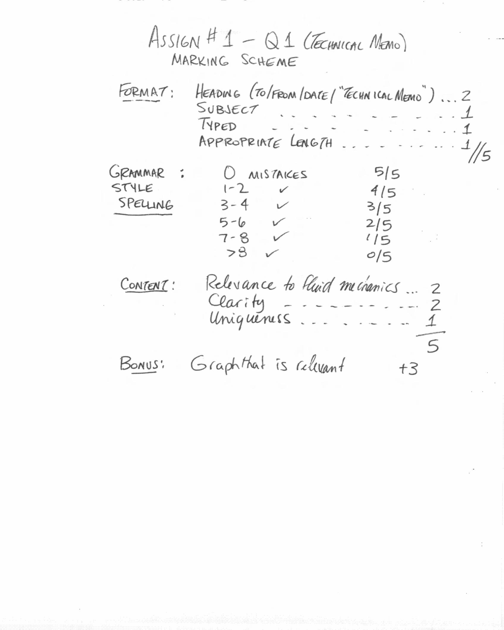
Assignment #1 Q1, Q3, Q4 Due 2:00pm, Mon. 18 Sept. 2006 Question 1 (15 marks) Write a “technical” memorandum (250-1000 words) that describes an experience you have had that you feel has some connection with fluid mechanics. You can use an experience from home, from your childhood or from a job you have had. For example, as a child, did you dig trenches to carry rainwater? Did you build moats around sand castles? Have you ever been in the shower when someone in the kitchen turns on the hot water tap? Do your best to describe how an understanding of fluid mechanics might be pertinent to the experience you are describing. Please complete this question individually even if you work on the remainder of the assignment in groups. Your submission will be graded using the following system: Format: 5 marks [should be typed on a separate piece(s) of plain white paper, but submitted with the rest of Assign #1. Proper format will be discussed in the Seminar and a sample Memo uploaded to the ChE 312 WebCT page] Grammar, Spelling & Style: 5 marks [Use of proper grammar, good spelling and a writing style that is clear and concise] Content: 5 marks [Relevance to fluid mechanics, clarity of description, appropriate length, uniqueness] Bonus Marks: 3 bonus marks if you figure out a way to include a graph of something relevant to the content of your memo! The authors of the “best” memos will receive snappy bonus prizes at the ChE 312 lecture on Mon. 25 Sept.
ChE 312 Assignment #1 11-18 Sept. 1
Question 2 (Problem 1.5, Text) A formula for estimating the volume rate of flow, Q, over the spillway of a dam is
( )3
222 2
VQ C g B H g= + , where C is a constant, g the acceleration of gravity, B the
spillway width, H the depth of water passing over the spillway, and V the velocity of water just upstream of the dam. Would this equation be valid in any system of units? Explain. Question 3 (Problem 1.17, Text) (10 marks) Table B.2 [Text, p.507] gives the density (ρ, kg/m3) and viscosity (µ, Pa.s) of water as a function of temperature. Determine an empirical equation for the variation of water density (kg/m3) with temperature (in ºC). Over what temperature range is your empirical equation most accurate? [HINT: Use an equation of the form ρ = c1 + c2T + c3T2 + c4T3] Question 4 (Problem 1.55/1.56, Mott) (10 marks)
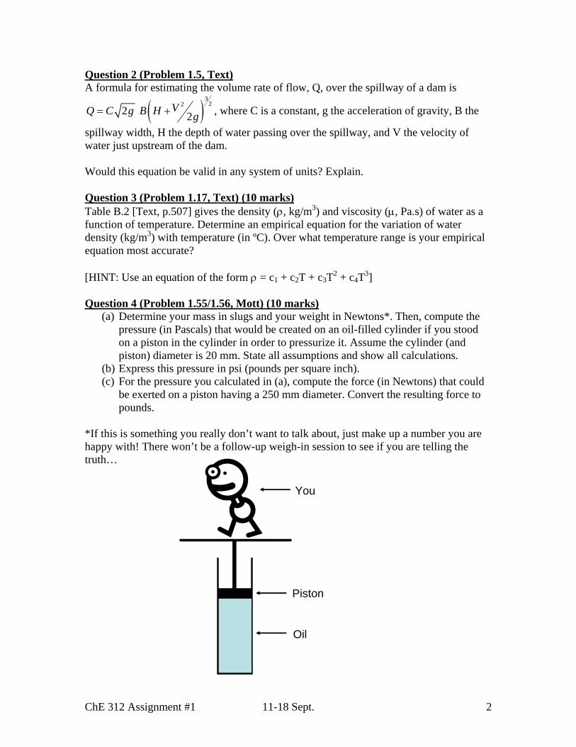
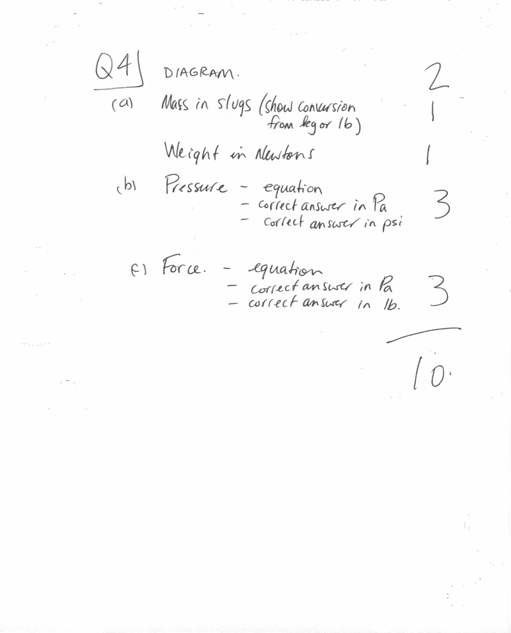
(a) Determine your mass in slugs and your weight in Newtons*. Then, compute the pressure (in Pascals) that would be created on an oil-filled cylinder if you stood on a piston in the cylinder in order to pressurize it. Assume the cylinder (and piston) diameter is 20 mm. State all assumptions and show all calculations.
(b) Express this pressure in psi (pounds per square inch). (c) For the pressure you calculated in (a), compute the force (in Newtons) that could
be exerted on a piston having a 250 mm diameter. Convert the resulting force to pounds.
*If this is something you really don’t want to talk about, just make up a number you are happy with! There won’t be a follow-up weigh-in session to see if you are telling the truth…
Oil
Piston
You
ChE 312 Assignment #1 11-18 Sept. 2
Additional Information: Please complete this page and return it with your completed Assign #1. Mid-Term Exam Date: Please choose the date that you would prefer for the mid-term exam. Please mark only 1 choice: ___ Wednesday, October 25 ___ Friday, October 27 ___ Friday, November 3 Office Hours: Please choose the office hours that would be most convenient for you. Please mark 3 choices: ___ Tuesdays, 1-2 pm ___ Wednesdays, 1-2 pm ___ Fridays, 1-2 pm ___ Tuesdays, 2-3 pm ___ Wednesdays, 2-3 pm ___ Fridays, 2-3 pm ___ Tuesdays, 3-4 pm ___ Wednesdays, 4-5 pm ___ Fridays, 3-4 pm ___ Sundays, 2-3 pm ___ Sundays, 3-4 pm Academic Integrity Review: I have reviewed the information on Academic Integrity that is presented in the ChE 312 Course Outline (Sept. 2006). I have also reviewed the document entitled “Don’t Cheatsheet” that is posted on the ChE 312 WebCT page. I have read and understood the definitions of plagiarism, cheating, misrepresentation of facts and participation in an offence. I understand that the University considers these to be serious academic offences. _______________________ Signature of student ________________________ Printed Name and Student Number
ChE 312 Assignment #1 11-18 Sept. 3


University of Alberta Department of Chemical and Materials Engineering
ChE 312 Fluid Mechanics Seminar #2 / Assignment #2
18-25 Sept. 2006
Questions Notes Seminar #2 Q2, Q4 To be done in seminar
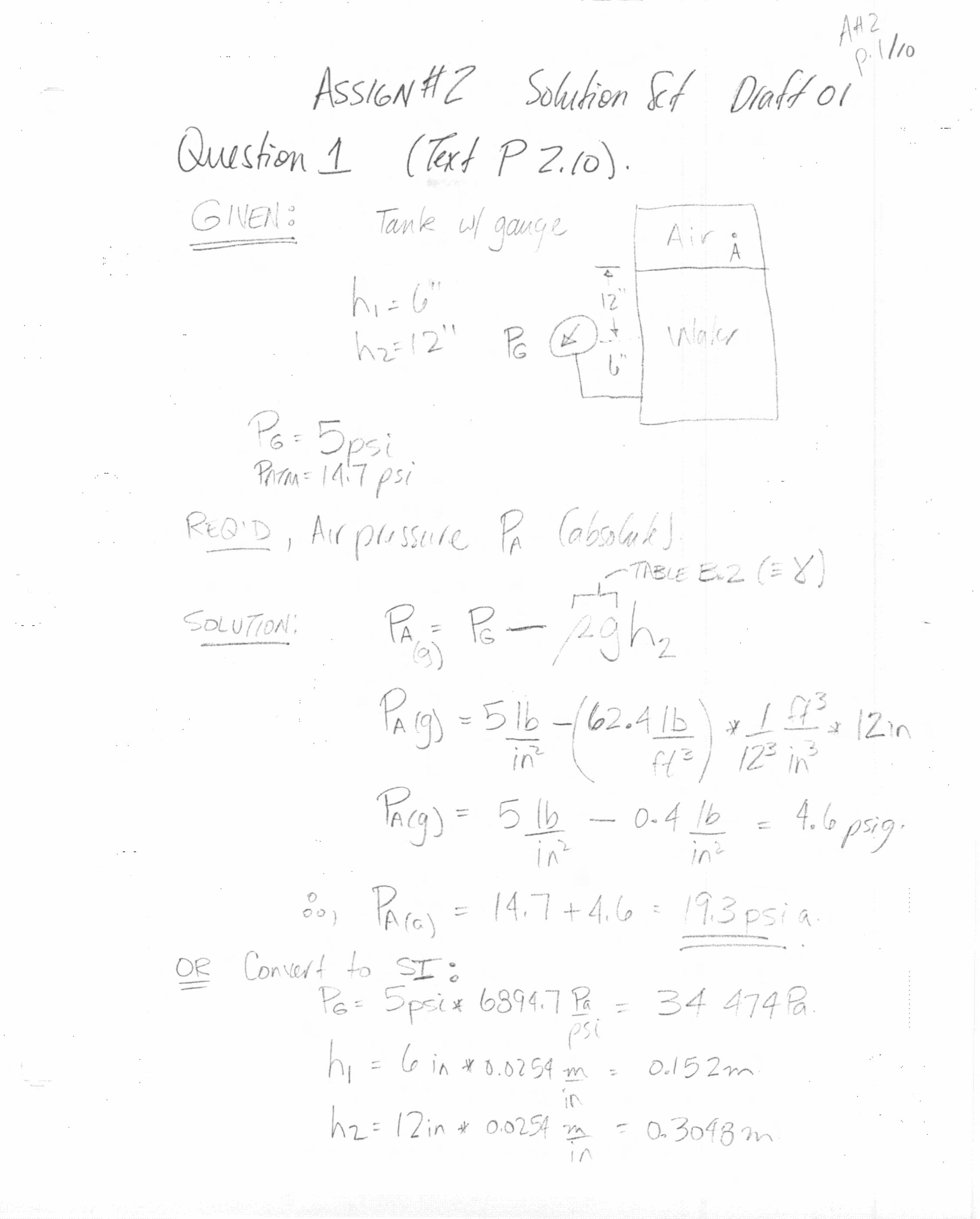
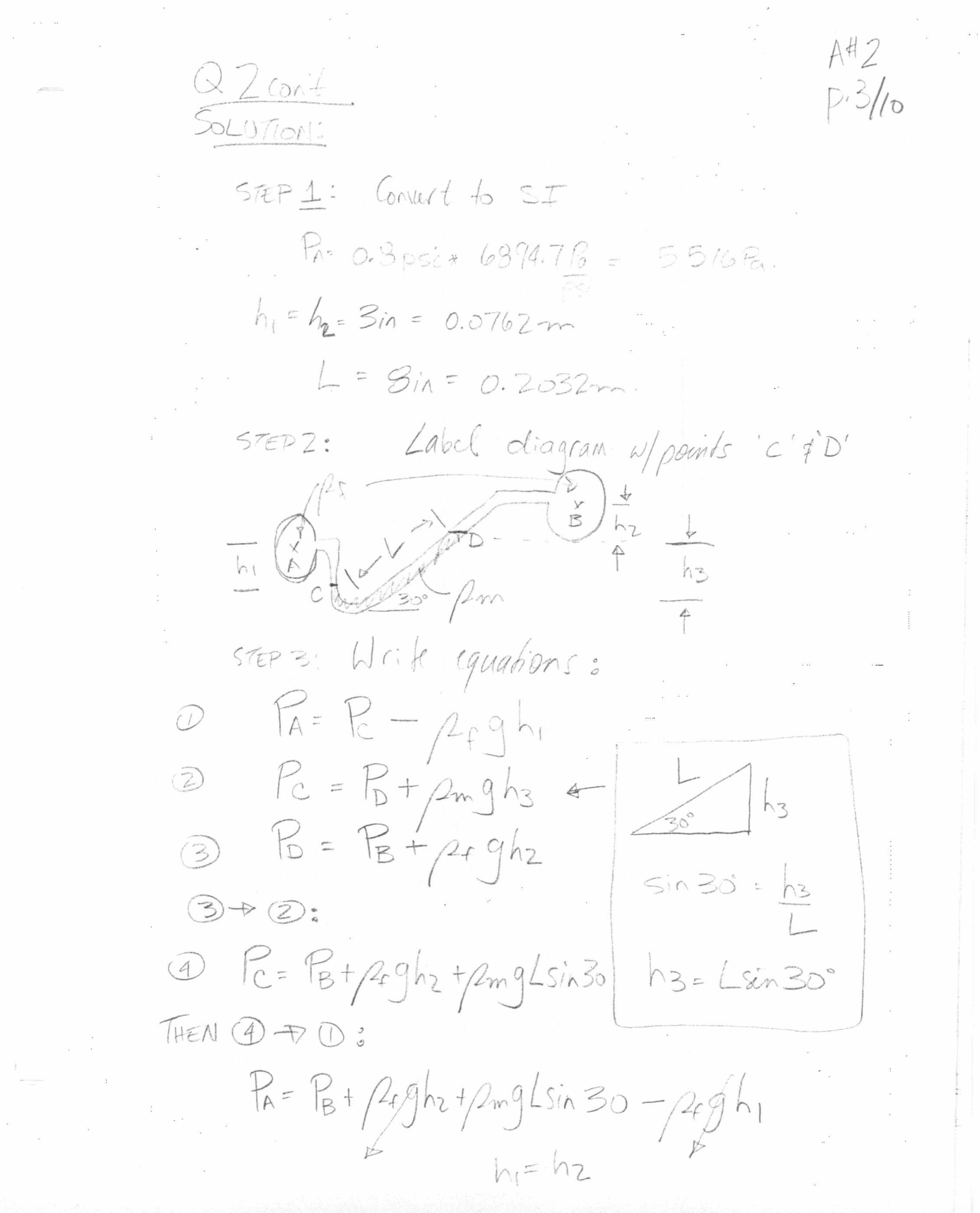
Assignment #2 Q1, Q3, Q5 Due 2:00pm, Mon. 25 Sept. 2006 Question 1 (Problem 2.10, Text) (10 marks) A Bourdon pressure gauge is attached to the closed water tank, as shown in the adjacent figure. If the gauge reads 5 psi, what is the absolute pressure of air in the tank? Assume atmospheric pressure is 14.7 psi and express your answer in these units. Question 2 (Problem 2.18, Text) For the inclined-tube manometer shown below, the pressure in pipe A is 0.8 psi. The fluid in both pipes A and B is water. The manometer fluid has a specific gravity of 2.6. What is the pressure in pipe B corresponding to the differential reading shown?
ChE 312 Assignment #2 18-25 Sept. 1

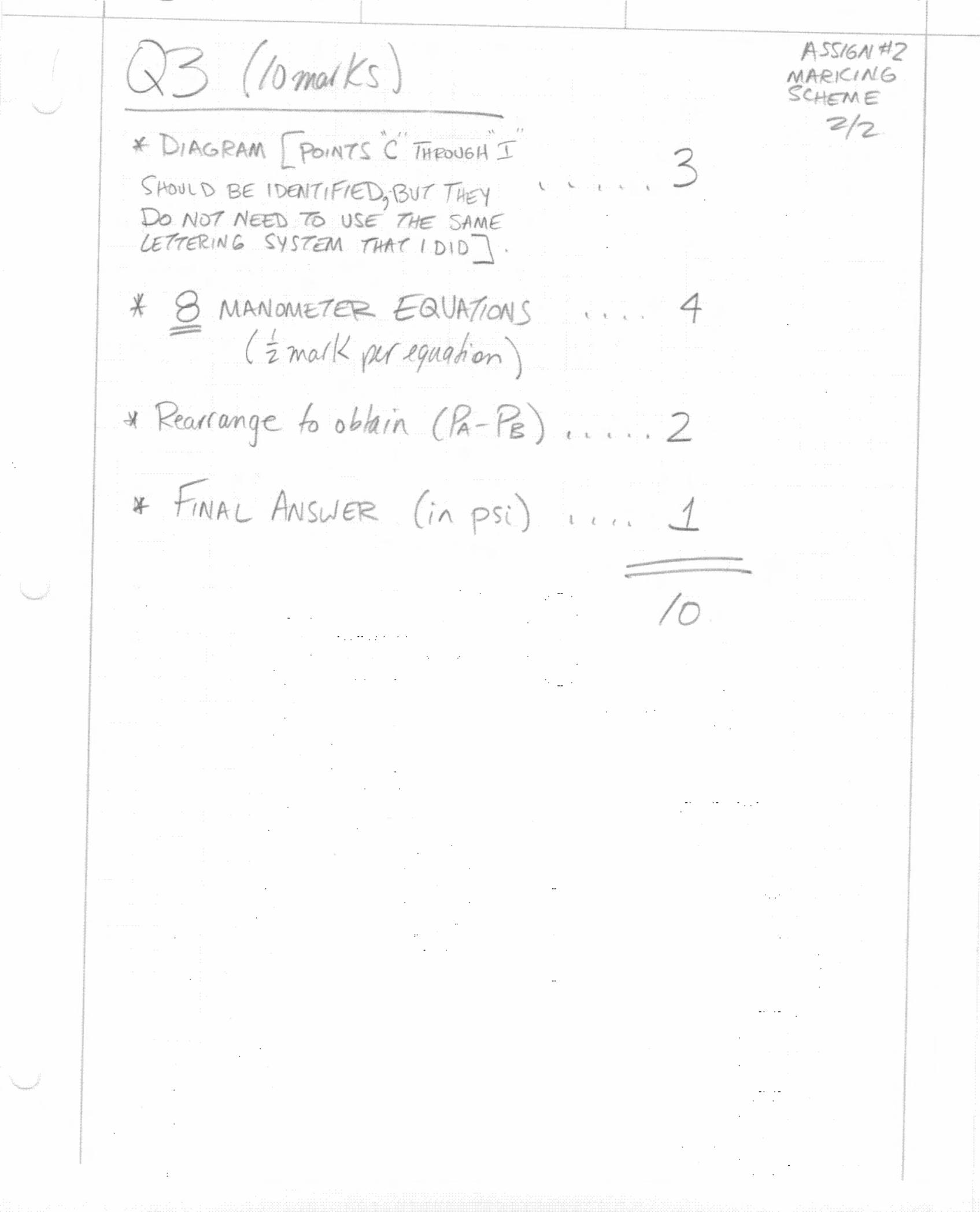
Question 3 (Problem 3.68, Mott) (10 marks)
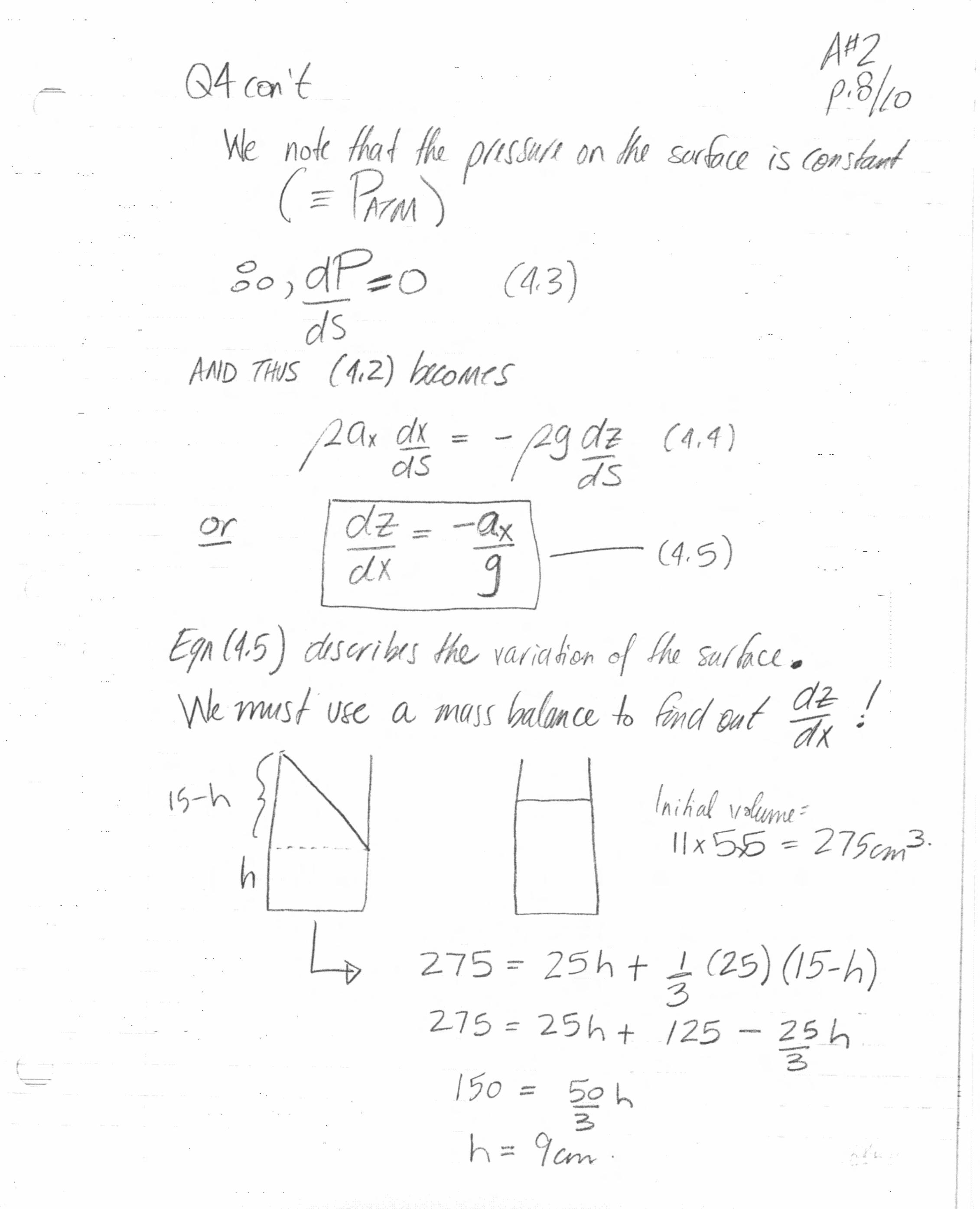
For the compound manometer shown in the adjacent figure, calculate (PA – PB). Express your answer in Pa and in psi. Question 4 What if, in the movie “The Fast and the Furious”, Vin Diesel’s street-racing bad-dude character (Dominic Toretto) was always trying to keep from spilling his open mug of coffee during street races? What would his maximum acceleration have been limited to? Would he have won many street races? Let’s assume the coffee mug has a 5 cm x 5 cm square cross section (for ease of calculation) and is 15 cm in height. Let’s also assume the mug is initially filled with coffee to a height of 11 cm. Question 5 (Problem 2.13, Gerhart & Gross) (10 marks) The solar pond shown in the figure, below, has a salt concentration that increases with water depth. The resulting water density increases as shown. (a) Find the gauge pressure at the bottom of the solar pond (in kPa); and (b) Calculate the gauge pressure if there were no salt in the pond.
ChE 312 Assignment #2 18-25 Sept. 2


University of Alberta Department of Chemical and Materials Engineering
ChE 312 Fluid Mechanics Seminar #3 / Assignment #3
25 Sept. - 02 Oct. 2006
Questions Notes Seminar #3 Q2**, Q4** To be handed in at seminar
Assignment #3 Q1, Q3 Due 2:00pm, Mon. 02 Oct. 2006 Question 1 (Problem 2.134, G&G*) (10 marks) An open tank of water accelerates upward at the rate of 4.0 ft/s2. The tank measures 1.0 ft x 1.0 ft x 20.0 ft high, and is half-filled with 60ºF water. Find the gauge pressure that would be measured at the bottom of the tank. Question 2 (10 marks) Prepare a problem (and a correct solution) that meets the following criteria:
• It is of the appropriate level of difficulty for students taking ChE 312; • It addresses one of the Module 1 learning objectives, OR can be solved with the
“useful” versions of the Conservation of Mass equation (Lecture Notes, Eq. 2.3a to 2.3e);
• It is NOT one of the questions in your textbook (this includes questions from the book where the numbers have been changed but the problem formulation is unchanged).
We will work in groups to complete this question. Each group member will receive a mark of 10/10 as long as the question and solution are submitted at the end of the seminar. Question 3 (Problem 5.9, Text) (10 marks) As shown in Fig. P5.9, at the entrance to a 3-ft-wide channel the velocity distribution is uniform with a velocity V. Further downstream the velocity profile is given by
24 2u y y= − where u is in feet per second and y is in feet. Determine the value of V. *Gerhart & Gross, Fundamentals of Fluid Mechanics, 2nd Ed. Addison-Wesley Publishing Company, 1992. **Question 2 and Question 4 count for 10/30 marks for this Assignment, but must be handed in at the end of the seminar and not with the other Assign #3 questions on 02 Oct.
ChE 312 Assignment #3 25 Sept.-02 Oct. 1
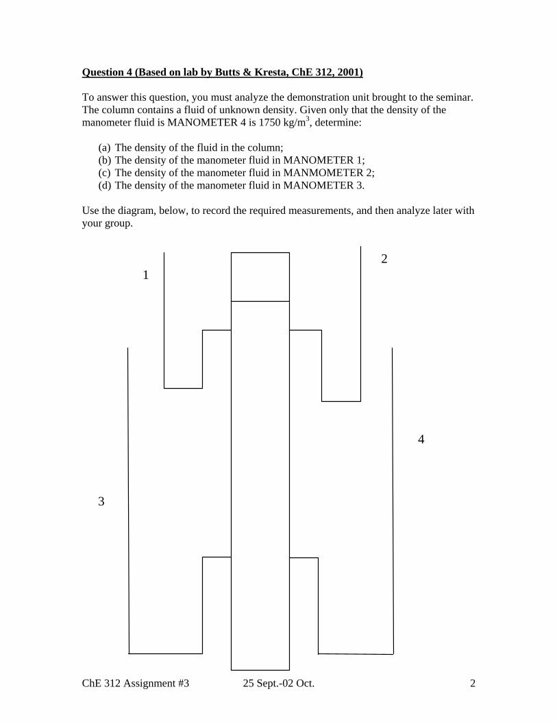
Question 4 (Based on lab by Butts & Kresta, ChE 312, 2001) To answer this question, you must analyze the demonstration unit brought to the seminar. The column contains a fluid of unknown density. Given only that the density of the manometer fluid is MANOMETER 4 is 1750 kg/m3, determine:
(a) The density of the fluid in the column; (b) The density of the manometer fluid in MANOMETER 1; (c) The density of the manometer fluid in MANMOMETER 2; (d) The density of the manometer fluid in MANOMETER 3.
Use the diagram, below, to record the required measurements, and then analyze later with your group.
12
3
4
ChE 312 Assignment #3 25 Sept.-02 Oct. 2

CHE 312 - Assignment #3 Solution 1
Question 1) Given: Tank dimension: surface area:1*1 ft*ft; Liquid height=10 ft ; Linear acceleration of tank upward, aZ=4.0 ft/s2 Required: Gauage pressure at bottom of tank: PA=?
Tank aZ g z0
60°F 20 ft 10 ft A Z zA X
Solution: Using Pressure field equation:
dzgadxadP ZX )(1+−−=
ρ
For the one dimensional acceleration just in z direction aX=0, this becomes:
dzagdP Z )( +−= ρ (1.1) Integration yields:
CzagP Z ++−= )(ρ (1.2) where C is integration constant To find integration constant; C, we know that at the free surface of the liquid, the guage pressure is zero, i.e.: P0=0 using equation (1.2) at the free surface of the liquid:
Czag Z ++−= 0)(0 ρ ⇒ 0)( zagC Z+= ρ (1.3) combining equation (1.2) and (1.3), pressure field equation becomes as:
0)()( zagzagP ZZ +++−= ρρ or
)(*)( 0 zzagP Z −+= ρ (1.4) Equation (1.4) can be applied for point A at the bottom of tank:
AA zzatPP == or
)(*)( 0 AZA zzagP −+= ρ (1.5)
CHE 312 - Assignment #3 Solution 2
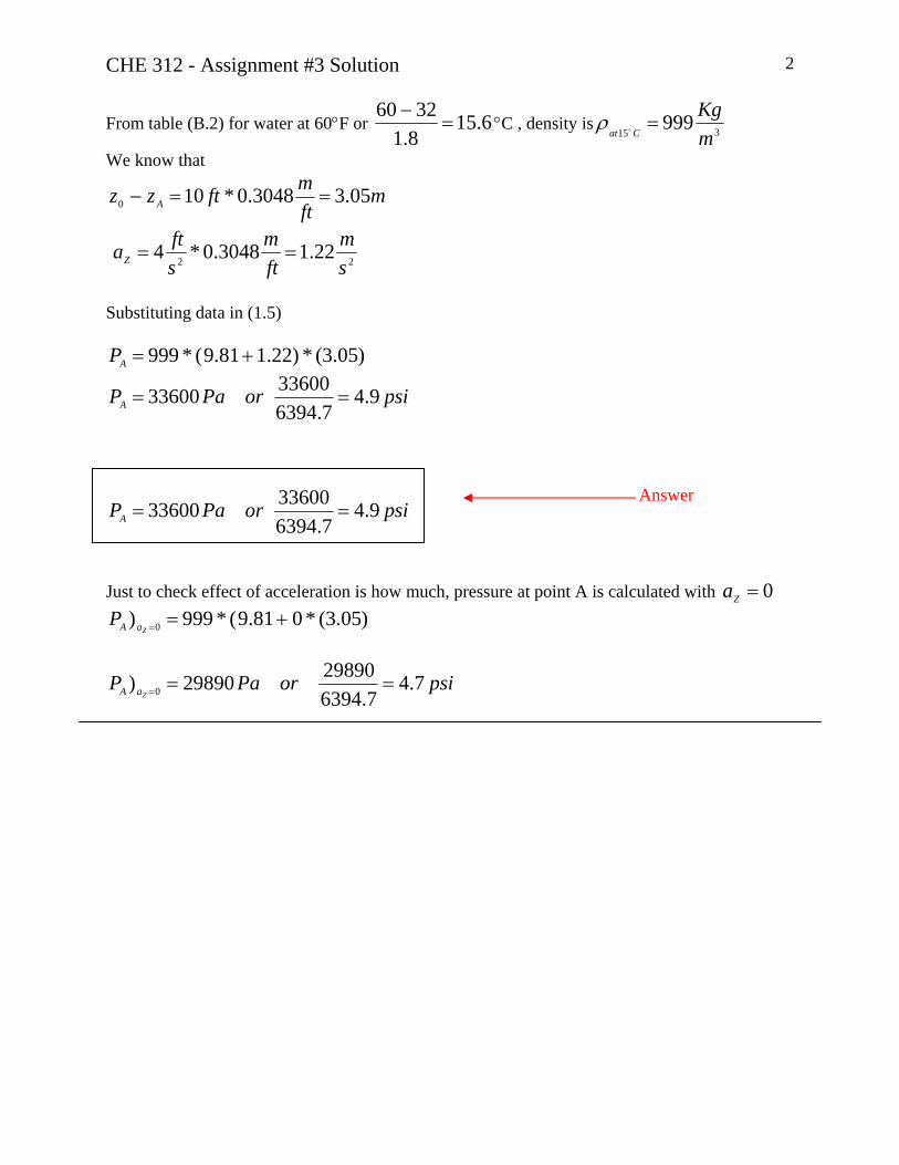
From table (B.2) for water at 60°F or 6.158.13260
=−
°C , density is 315999
mKg
Cat=ρ
We know that
mftmftzz A 05.33048.0*100 ==−
22 22.13048.0*4
sm
ftm
sftaZ ==
Substituting data in (1.5)
)05.3(*)22.181.9(*999 +=AP
psiorPaPA 9.47.6394
3360033600 ==
psiorPaPA 9.47.6394
3360033600 ==
Answer
Just to check effect of acceleration is how much, pressure at point A is calculated with 0=Za
)05.3(*081.9(*999) 0 +==ZaAP
psiorPaPZaA 7.4
7.63942989029890) 0 ===

CHE 312 - Assignment #3 Solution 3
Question 3)
Given: Channel entrance height, Velocity profile some where in down stream with specified height Required: (a) Entrance Velocity, V1=?
224 yyu −= ft/s 1.0 ft y V1 0.75 ft x 1 2
Solution:
.const=ρ which means 21 ρρ = Assume Using mass balance: 222111 AVAV ρρ = ⇒ 2211 AVAV = Average velocity in location 2; V2 ,is equal to average velocity of 2u , i.e.
2211 AuAV = (1.3)
2u can be calculated by:
∫∫=
=
−==fty
yA
dyyybdAuAu1
0
222 ].24[.
2
so
10
3222 ]
32
24[* yybAu −=
bbAu34]01*
321*
24[*22 =−−= (2.3)
Substituting equation (2.3) in (1.3)
bbV34)*75.0(*1 = ⇒
)75.0*3(4
1 =V
sftV 78.11 =
Answer

University of Alberta Department of Chemical and Materials Engineering
ChE 312 Fluid Mechanics Seminar #4 / Assignment #4
02 - 10 Oct. 2006
Questions Notes Seminar #4 Q2, Q4 Example problems worked in seminar
Assignment #3 Q1, Q3, Q5 Due 2:00pm, TUES. 10 Oct. 2006 Question 1 (10 marks) List all the major steps that were required to develop the Mechanical Energy Balance. Use your lecture notes as a guide. (Hint: there should be 8 steps!) Question 2 (E4.7, G&G*) Water is being added to a storage tank at the rate of 500 gal/min. At the same time water flows out the bottom through a pipe that is 2.0” in diameter with an average velocity of 60 ft/s, as shown in the adjacent diagram. Find the rate at which the water level rises or falls. Question 3 (Problem 4.31, G&G*) (10 marks) In the vortex tube shown below, air enters at 202 kPa and 300K. Hot air leaves at 150 kPa-g and 350K, whereas cold air leaves at 101 kPa-g and 250K. The hot air mass flow
rate, , equals the cold air mass flow rate, Hm•
Cm•
. Find the ratio of the hot air exit area to cold air exit area for equal exit velocities.
*Gerhart & Gross, Fundamentals of Fluid Mechanics, 2nd Ed. Addison-Wesley Publishing Company, 1992.
ChE 312 Assignment #4 02 Oct.-10 Oct. 1
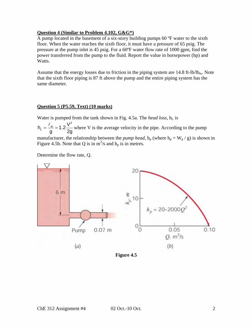
Question 4 (Similar to Problem 4.102, G&G*) A pump located in the basement of a six-story building pumps 60 ºF water to the sixth floor. When the water reaches the sixth floor, it must have a pressure of 65 psig. The pressure at the pump inlet is 45 psig. For a 60ºF water flow rate of 1000 gpm, find the power transferred from the pump to the fluid. Report the value in horsepower (hp) and Watts. Assume that the energy losses due to friction in the piping system are 14.8 ft-lb/lbm. Note that the sixth floor piping is 87 ft above the pump and the entire piping system has the same diameter. Question 5 (P5.59, Text) (10 marks) Water is pumped from the tank shown in Fig. 4.5a. The head loss, hL is
2w
LVh 1.2
g 2= =
gwhere V is the average velocity in the pipe. According to the pump
manufacturer, the relationship between the pump head, hp (where hp = Wp / g) is shown in Figure 4.5b. Note that Q is in m3/s and hp is in metres. Determine the flow rate, Q.
Figure 4.5
ChE 312 Assignment #4 02 Oct.-10 Oct. 2
CHE 312 - Assignment #4 Solution 1
Question 1)
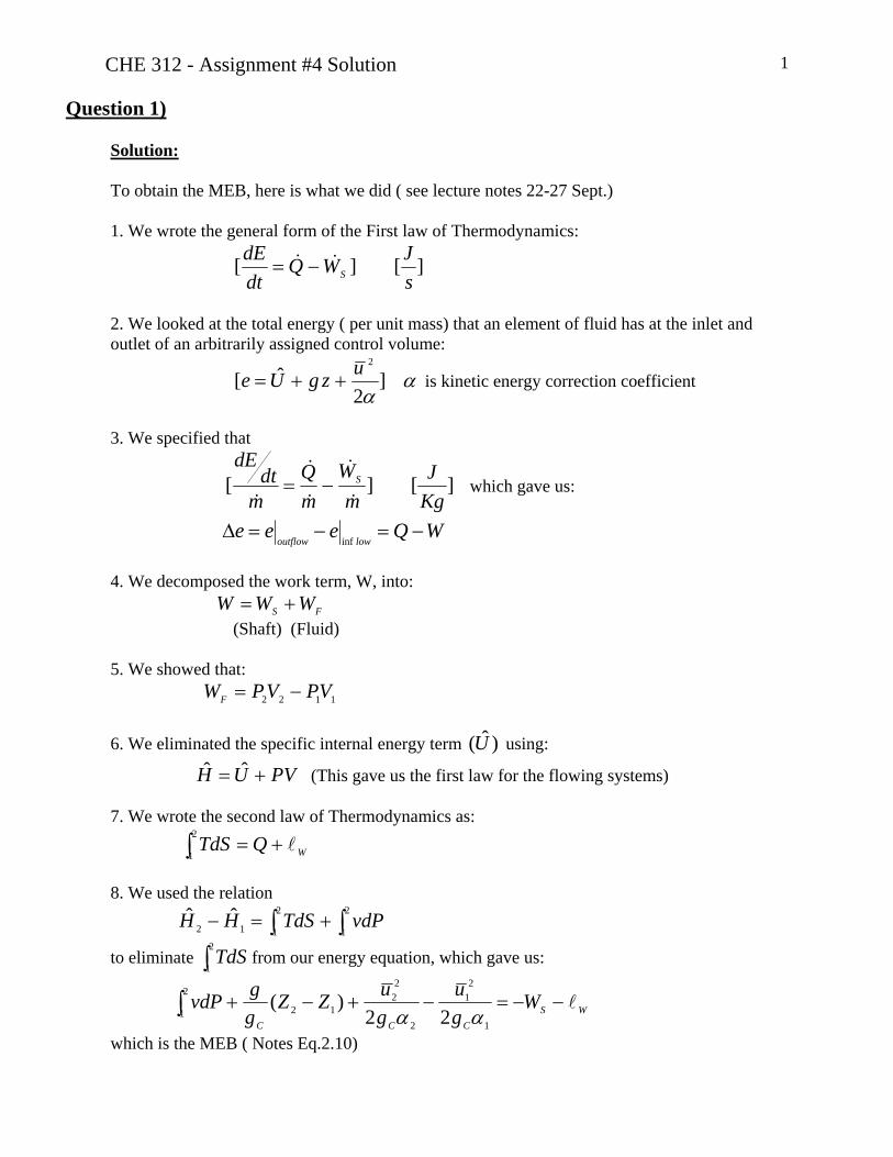
Solution: To obtain the MEB, here is what we did ( see lecture notes 22-27 Sept.) 1. We wrote the general form of the First law of Thermodynamics:
][][sJWQ
dtdE
S&& −=
2. We looked at the total energy ( per unit mass) that an element of fluid has at the inlet and outlet of an arbitrarily assigned control volume:
αα
]2
ˆ[2uzgUe ++= is kinetic energy correction coefficient
3. We specified that
][][KgJ
mW
mQ
mdt
dES
&
&
&
&
&−= which gave us:
WQeeelowoutflow
−=−=Δinf
4. We decomposed the work term, W, into: FS WWW += (Shaft) (Fluid) 5. We showed that: 1122 VPVPWF −= 6. We eliminated the specific internal energy term using: )ˆ(U PVUH += ˆˆ (This gave us the first law for the flowing systems) 7. We wrote the second law of Thermodynamics as: WQTdS l+=∫
2
1
8. We used the relation ∫∫ +=−
2
1
2
112ˆˆ vdPTdSHH
to eliminate from our energy equation, which gave us: ∫2
1TdS
WSCCC
Wgu
guZZ
ggvdP l−−=−+−+∫
1
21
2
22
12
2
1 22)(
αα
which is the MEB ( Notes Eq.2.10)

CHE 312 - Assignment #4 Solution 2
Question 2)
Given: Qin 500=& gpm
ftDT 10=
sftV eDisch 60arg = Velocity at discharge pipe
DP=2 in Required: Rate at which the water level rises or
falls (i.e.) ?=dtdh
inm& h 1∀ 2∀ DP=2 in VP
outm&Solution: For the control volume as shown: 21 ∀+∀=∀ (because of tank shape)
Conservation of mass is: outinW mmdtd
&& −=∀ρ
where (A221 . ∀+=∀+∀=∀ hAT T is cross sectional area of tank)
PPWout AVm ρ=&
Qm Win&& ρ=
Or
PPWWTW AVQhAdtd ρρρ −=∀+ &].[ 2
Or PPT AVQdtdhA −= &
And finally:
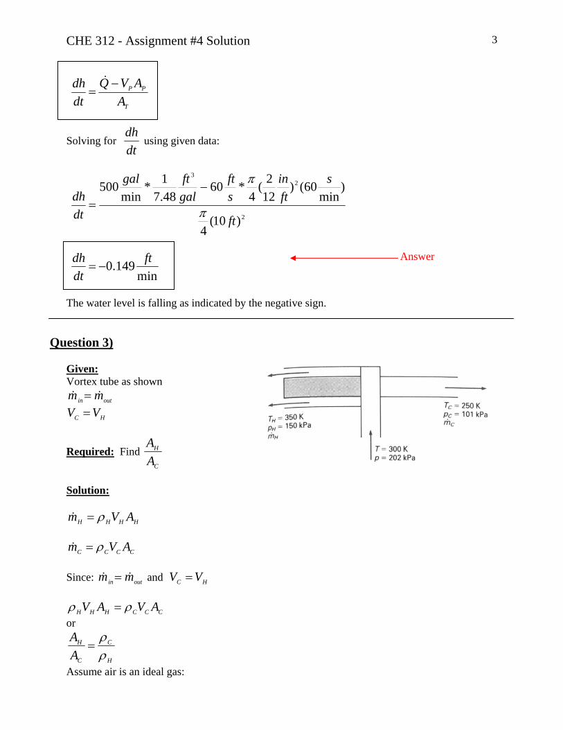
CHE 312 - Assignment #4 Solution 3
T
PP
AAVQ
dtdh −
=&
Solving for dtdh
using given data:
2
23
)10(4
)min
60()122(
4*60
48.71*
min500
ft
sftin
sft
galftgal
dtdh
π
π−
=
min149.0 ft
dtdh
−=
Answer
The water level is falling as indicated by the negative sign.
Question 3)
Given: Vortex tube as shown
outin mm && =
HC VV =
Required: Find C
H
AA
Solution:
HHHH AVm ρ=&
CCCC AVm ρ=& Since: and outin mm && = HC VV =
CCCHHH AVAV ρρ = or
H
C
C
H
AA
ρρ
=
Assume air is an ideal gas:

CHE 312 - Assignment #4 Solution 4
CCC RTP ρ=
HHH RTP ρ=
So: ))(())((C
H
H
C
H
H
C
C
C
H
TT
PP
PRT
RTP
AA
==
So )250350)(
150101101101(
++
=C
H
AA
13.1=C
H
AA
Answer
Note: Absolute pressures must be used in ideal gas law.
Question 4) Given:
Inlet and outlet line pressure P1=45 psig ; P2=65psig Volumetric flow rate: Q=1000 gpm Energy losses due to friction in the piping system:
mW lb
lbft.8.14=l
Required:
Transferred power from pump to the fluid; -(-WP) or (-WS)When η=1
2 6th floor 87 ft 1 Basement
Solution: For sake of calculation, all the data are converted to SI units
gPapsiPapsigP .3102617.6894*451 ==
gPapsiPapsigP .4481557.6894*652 ==
mft
mftZZ 5.262808.31*8712 ==−
sm
USgpmsmUSgpmQ
335 0631.0/10*31.6*1000 == −&

CHE 312 - Assignment #4 Solution 5
KgJ
Kglb
lbftJ
lblbft
m
fm
fW 2.44
453.01*
.356.1*
.8.14 ==l
Assumption: -Since there is not any change in the pipe diameter in the flow path: 21 uu = - Kinetic energy correction factor is constant and equal to unit: 0.121 ==αα
- Fluid density is constant: 315@60@999
mKg
CWFW== oo ρρ
Now Mechanical Energy Balance; MEB, can be written between point 1 and 2 shown on the drawing:
WPCCC
Wgu
guZZ
ggPP
l−−−=−+−+− )(
22)()(
1
21
2
22
1212
ααρ
The negative sign beside (–WP) term is because work is being added to system By rearranging and using assumption for α,u :
WC
P ZZggPPW l+−+
−= )()(
1212
ρ
Using given data:
2.445.26*81.9999
)310261448155(++
−=PW
KgJWP 2.442= required work per unit mass of fluid
So to obtain total transferred power to fluid:
PPP WQWmW &&& ρ== * )2.442(*)0631.0(*)999(=
WWP 27875=& or KWWP 9.27=& Answer
To obtain in horse power1 unit:
KWhpKWWP 7457.0
1*9.27=&
hpWP 4.37=&
Answer

CHE 312 - Assignment #4 Solution 6
Question 5) Given:
Fluid is Water Liquid height in tank; h1-2=6m (=Z1-Z2)
Head loss: g
Vg
h WL 2
2.12
==l
Outlet pipe diameter; D2=0.07m Relationship between pump head; hp, and pump flow rate; Q as
2200020 QhP −= where hP is in [m] and Q in [m3/s] Required:
Flow rate; Q=?
∇ 1 Z h1-2 2
Solution: Assumption: -Since tank diameter is large, we can neglect fluid velocity at point 1: 01 =u - Kinetic energy correction factor is constant and equal to unit: 0.121 ==αα - Fluid density is constant: .constW =ρ - Pressure at both point 1 and 2 is atmospheric; P1=P2= PAtm Now Mechanical Energy Balance; MEB, can be written between point 1 and 2 as shown on the drawing:
WPCCC
Wgu
guZZ
ggPP
l−−−=−+−+− )(
22)()(
1
21
2
22
1212
ααρ (5.1)
Using assumption equation (5.1) can be rearranged as:
ggW
guZZ WP l
−=+−2
)(2
212
Looking at the drawing we can see that 2112 )( −−=− hZZ , so:
LP hhg
uh −=+− − 2
22
21 (5.2)
Using given correlation for : LP handh
guQ
guh
22.1)200020(
2
222
22
21 −−=+− − where 2uV =
This equation can be rearranged as:

CHE 312 - Assignment #4 Solution 7
guQh2
2.2)200020(2
2221 −−=− − (5.3)
Average velocity at point 2; 2u , can be written as flow rate and pipe cross sectional area as:
222 *4
)4
*( DQ
DQ
AQuPipe ππ
=== (5.4)
Combining equation (5.3) and (5.4):
gDQ
Qh2
)4(2.2)200020(
22
221
π−−=− −
)6.172000(2042
2
DgQ
π+−=
After rearranging:
)6.172000(
)20(
42
212
Dg
hQ
π+
+= −
Using the given data:
7571200026
)))07.0(**81.9(
6.172000(
)620(
42
2
+=
+
+=
π
Q
9571262 =Q
Or
smQ
3
052.0=
Answer
University of Alberta Department of Chemical and Materials Engineering
ChE 312 Fluid Mechanics Assignment #5
06 - 16 Oct. 2006
Questions Notes Seminar #5 N/A No Seminars scheduled
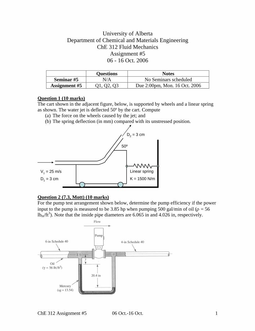
Assignment #5 Q1, Q2, Q3 Due 2:00pm, Mon. 16 Oct. 2006 Question 1 (10 marks) The cart shown in the adjacent figure, below, is supported by wheels and a linear spring as shown. The water jet is deflected 50º by the cart. Compute
(a) The force on the wheels caused by the jet; and (b) The spring deflection (in mm) compared with its unstressed position.
uestion 2 (7.3, Mott) (10 marks)
V1 = 25 m/s
D1 = 3 cm
Linear spring
K = 1500 N/m
D2 = 3 cm
50º
Q below, determine the pump efficiency if the power For the pump test arrangement shown
input to the pump is measured to be 3.85 hp when pumping 500 gal/min of oil (ρ = 56 lbm/ft3). Note that the inside pipe diameters are 6.065 in and 4.026 in, respectively.
ChE 312 Assignment #5 06 Oct.-16 Oct. 1

Question 3 (Problem 4.198, G&G*) (10 marks) Find the forces Fx and Fy required to hold steady the tank shown in the figure below. The pipe diameter D is that required for a constant water level. Assume ideal flow and neglect the weight of the tank.
ChE 312 Assignment #5 06 Oct.-16 Oct. 2

CHE 312 - Assignment #5 Solution 1
Question 1)
Solution: Momentum balance problem a) Momentum balance on y- direction:
][* 12 yyyyGyDyP uumRFFF −=−++
Since P2=PAtm; 0=yPFNo motion of C.V.; so 0=yDFmass of cart and water is negligible: 0=yGF
01 =yu
yy umR 2*=− Using mass balance for water jet and since jet diameter is equal at point 1 and 2:
12 uu = Mass flow can be calculated by:
sKg
uAm
67.174
)25()03.0(*)1000(..
2
==
=
πρ
50sin22 uu y =
2u yu2
xu2
Given: As indicated on figure: Required: a) Force on Wheels (Ry) by Water jet b) Deflection of spring, X∆ in [mm] Assumption: neglect mass of cart and water Assume 1=β Control volume: Cart+Fluid
y 2 x 1 RX Ry
)50sin*25)(67.17(=− yR
NRy 4.338=−
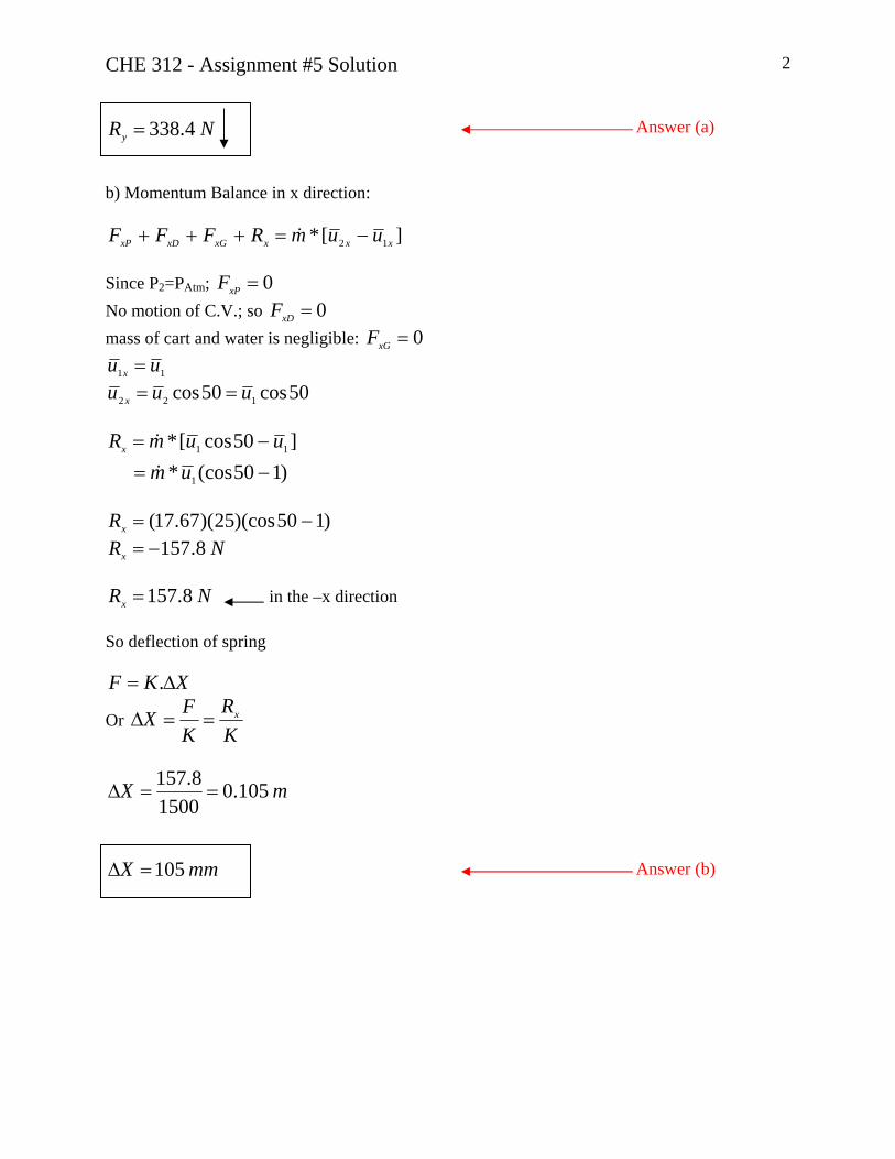
CHE 312 - Assignment #5 Solution 2
NRy 4.338= Answer (a)
b) Momentum Balance in x direction:
][* 12 xxxxGxDxP uumRFFF −=+++ Since P2=PAtm; 0=xPFNo motion of C.V.; so 0=xDFmass of cart and water is negligible: 0=xGF
11 uu x = 50cos50cos 122 uuu x ==
)150(cos*]50cos[*
1
11
−=−=
umuumRx
)150)(cos25)(67.17( −=xR
NRx 8.157−=
NRx 8.157= in the –x direction So deflection of spring
XKF ∆= .
Or KR
KFX x==∆
mX 105.01500
8.157==∆
mmX 105=∆ Answer (b)

CHE 312 - Assignment #5 Solution 3
Question 2)
Given: Data as shown on figure D1=6.065 in D2=4.026 in Q=500 USGPM hp 3.85][ =− SW Required: Pump efficiency, ?=Pη
hab
b a
Solution: Write MEB between points 1&2
WPcccf
Whhgg
gu
guPP
−−=−+−+− )(
22)(
121
21
2
2212
ααρ
where SPP WW η= Assumptions for simplification:
21 ZZ = 0.121 ==αα
friction between point 1&2 is negligible, 0=W 1=cg in SI system
22 A
Qu =
11 A
Qu =
So that MEB becomes:
Pf
WDQ
DQPP
−=⎥⎦
⎤⎢⎣
⎡−⎥
⎦
⎤⎢⎣
⎡+
−2
21
2
22
12 4214
21)(
ππρ (2.1)
To obtain , we analyze the manometer: ( see notation on the diagram) )( 12 PP −
yghgPP fmabmb ρρ −−=1
ba PP =

CHE 312 - Assignment #5 Solution 4
][2 yhgPP abfa +−= ρ By combining these three equations:
yghgyhgPP fabmabf ρρρ −−++= ][21 or
abfabm hgghPP ρρ −=− 12 or
⎥⎦
⎤⎢⎣
⎡−=
− 1)( 12
f
mab
f
ghPPρρ
ρ (2.2)
Now solve for (-WP) by substituting (2.2) into (2.1):
Pf
mab W
DDQgh −=⎥
⎦
⎤⎢⎣
⎡−+⎥
⎦
⎤⎢⎣
⎡−
41
42
2
2 1181πρ
ρ (2.3)
For pump 0>− PW Convert all the given data to SI units:
sm
USGPMs
mUSGPMQ
33
5 0316.010*31.6*500 == −
minminD 1541.00254.0*065.61 ==
minminD 1023.00254.0*026.42 ==
33
3
33 896)3048.0(
1*453.0*56mKg
mft
lbKg
ftlb
m
mf ==ρ
Substituting data in the equation (2.3):
][)1541.0(
1)1023.0(
1)0316.0(81896
13540)5182.0)(81.9(442
2
PW−=⎥⎦
⎤⎢⎣
⎡−+⎥⎦
⎤⎢⎣⎡ −
π
KgWP
J77.75.9571.74][ =+=−
QWmWW PPP .].[].[ ρ−=−=−

CHE 312 - Assignment #5 Solution 5 W2200)0316.0)(896)(7.77( ==
or WhpWhpWS 28717.745*85.3][ ==−
77.028712200
][][
=−−
=S
P
WWη
%77=η Answer
Question 3)
Given: Data as shown in the figure Water Temperature: 60°F
(a) 1 2 L
Required: XF , to hold tank steady=? YF Assumption: for simplification: Neglect the weight of Tank Assume ideal flow
360@999.;
2 mKgconst
FOH== ρρ
0.121 ==ββ 1=Cg in SI system
AtmPPP == 12 Solution: Momentum balance in X direction for the C.V shown by dashed boundary:
0. 2 −= XX umF no momentum flux in flow x-direction so
2.umFX = (3.1)

CHE 312 - Assignment #5 Solution 6 Momentum balance in the Y direction:
yaYyG umFF .0 −=+−
where sftuu aya 20−=−= ;and, gFyG ∀= ρ
Volume of control volume: LAhAt .. 2+=∀ so
aY umgF .+∀= ρ
atY umgLAhAF .)..( 2 ++= ρ (3.2) We must obtain 2u using MEB between point 1&2
0)(22
)(12
1
21
2
2212 =−+−+
− ZZgg
gu
guPP
cccf ααρ (3.3)
Using these:
01 =u hZZ −=− 12 0.121 ==αα
AtmPPP == 21 in SI system 1=cgequation (3.3) becomes:
0)(02
22 =−+− hgu
⇒ ghu 22 = (3.4)
mfth 048.310 ==
So using equation(3.4):
smu 73.7)048.3)(81.9(22 ==
sKg
ftm
sftQm 1414)3048.0(*)50)(999(.
3
33
3
=== ρ
Now equation (3.1) can be solved:
NumFX 10933)73.7)(1414(. 2 ===

CHE 312 - Assignment #5 Solution 7
ff lbN
lbN 2460
448.41
*10933 ==
Once we find A2, we can solve Eq (3.2)
23
22 183.0
73.7)3048.0)(50( m
uQA ===
mftLftfthmftAt
1.620048.310
23.224 22
======
so
)3048.90)(20)(1414()81.9)(1.6*183.0048.3*23.2)(999( ++=YF NFY 86170862077550 =+=
ff lbN
lbN 19400
448.41
*86170 ==
fX lbF 2460=
Answer
fY lbF 19400=
Answer
ChE 312 Assignment #6 16 Oct.-23 Oct. 1
University of Alberta Department of Chemical and Materials Engineering
ChE 312 Fluid Mechanics Assignment #6
16 - 23 Oct. 2006
Questions Notes Seminar #6 Q2, Q4 Will be worked in seminar
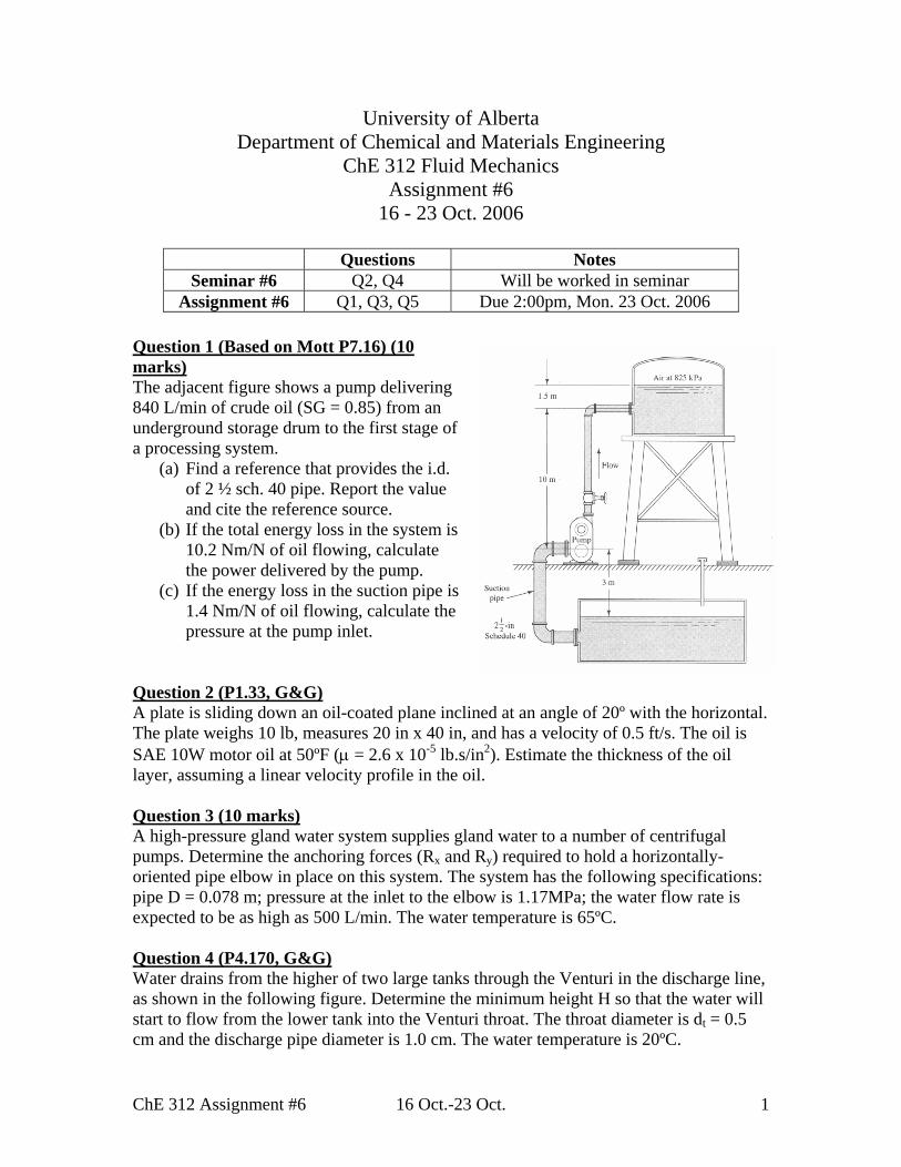
Assignment #6 Q1, Q3, Q5 Due 2:00pm, Mon. 23 Oct. 2006 Question 1 (Based on Mott P7.16) (10 marks) The adjacent figure shows a pump delivering 840 L/min of crude oil (SG = 0.85) from an underground storage drum to the first stage of a processing system.
(a) Find a reference that provides the i.d. of 2 ½ sch. 40 pipe. Report the value and cite the reference source.
(b) If the total energy loss in the system is 10.2 Nm/N of oil flowing, calculate the power delivered by the pump.
(c) If the energy loss in the suction pipe is 1.4 Nm/N of oil flowing, calculate the pressure at the pump inlet.
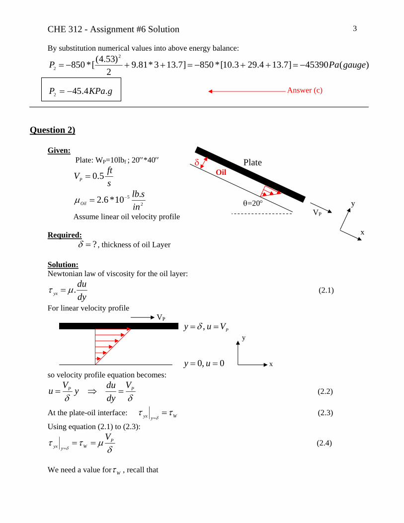
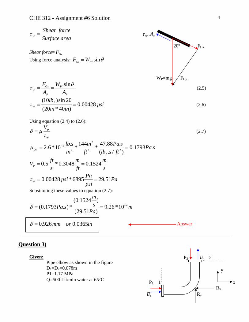
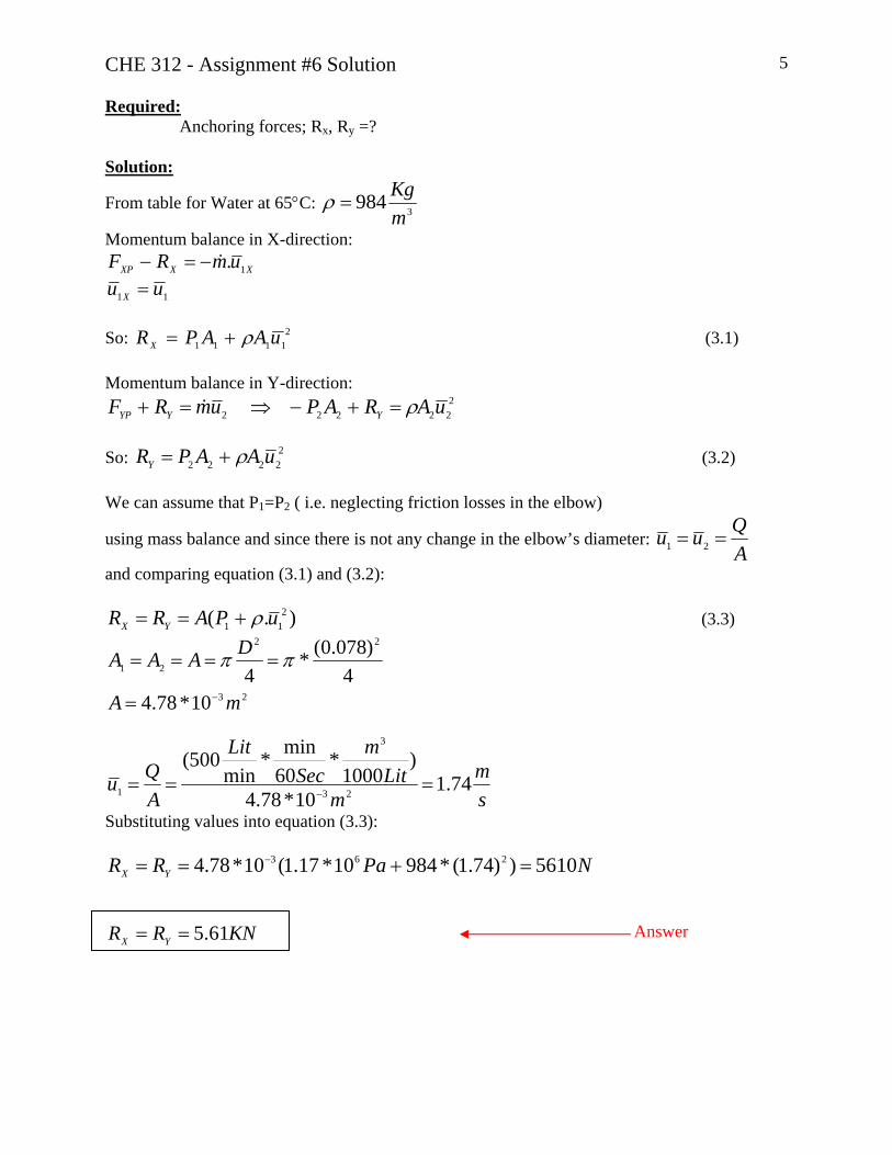
Question 2 (P1.33, G&G) A plate is sliding down an oil-coated plane inclined at an angle of 20º with the horizontal. The plate weighs 10 lb, measures 20 in x 40 in, and has a velocity of 0.5 ft/s. The oil is SAE 10W motor oil at 50ºF (µ = 2.6 x 10⁻⁵ lb.s/in2). Estimate the thickness of the oil layer, assuming a linear velocity profile in the oil. Question 3 (10 marks) A high-pressure gland water system supplies gland water to a number of centrifugal pumps. Determine the anchoring forces (Rx and Ry) required to hold a horizontally-oriented pipe elbow in place on this system. The system has the following specifications: pipe D = 0.078 m; pressure at the inlet to the elbow is 1.17MPa; the water flow rate is expected to be as high as 500 L/min. The water temperature is 65ºC. Question 4 (P4.170, G&G) Water drains from the higher of two large tanks through the Venturi in the discharge line, as shown in the following figure. Determine the minimum height H so that the water will start to flow from the lower tank into the Venturi throat. The throat diameter is dt = 0.5 cm and the discharge pipe diameter is 1.0 cm. The water temperature is 20ºC.

ChE 312 Assignment #6 16 Oct.-23 Oct. 2
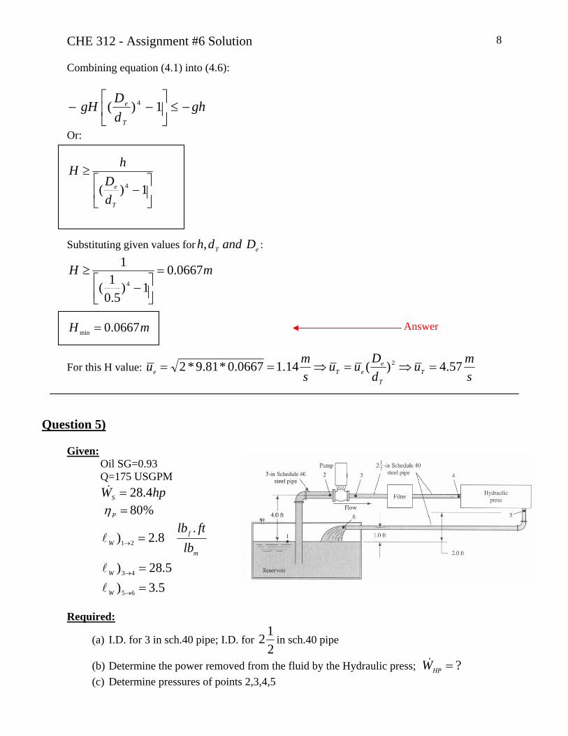
Question 5 (Based on Mott P7.35) (10 marks) The figure (below) shows a diagram of a fluid power system for a hydraulic press used to extrude rubber parts. The following data are known:
• The fluid is oil (SG = 0.93); • The flow rate is 175 USGPM; • The power input to the pump is 28.4 hp; • The pump efficiency is 80%; • The energy losses (in lb-ft/lb) are: 2.8 (from 1 to 2); 28.5 (from 3 to 4); 3.5 (from
5 to 6). Determine:
(a) From a reference source, the pipe i.d. for 3 in sch. 40 pipe and for 2 ½ in sch. 40 pipe;
(b) The power removed from the fluid by the hydraulic press; (c) Determine the pressures at points 2, 3, 4 and 5.
CHE 312 - Assignment #6 Solution 1
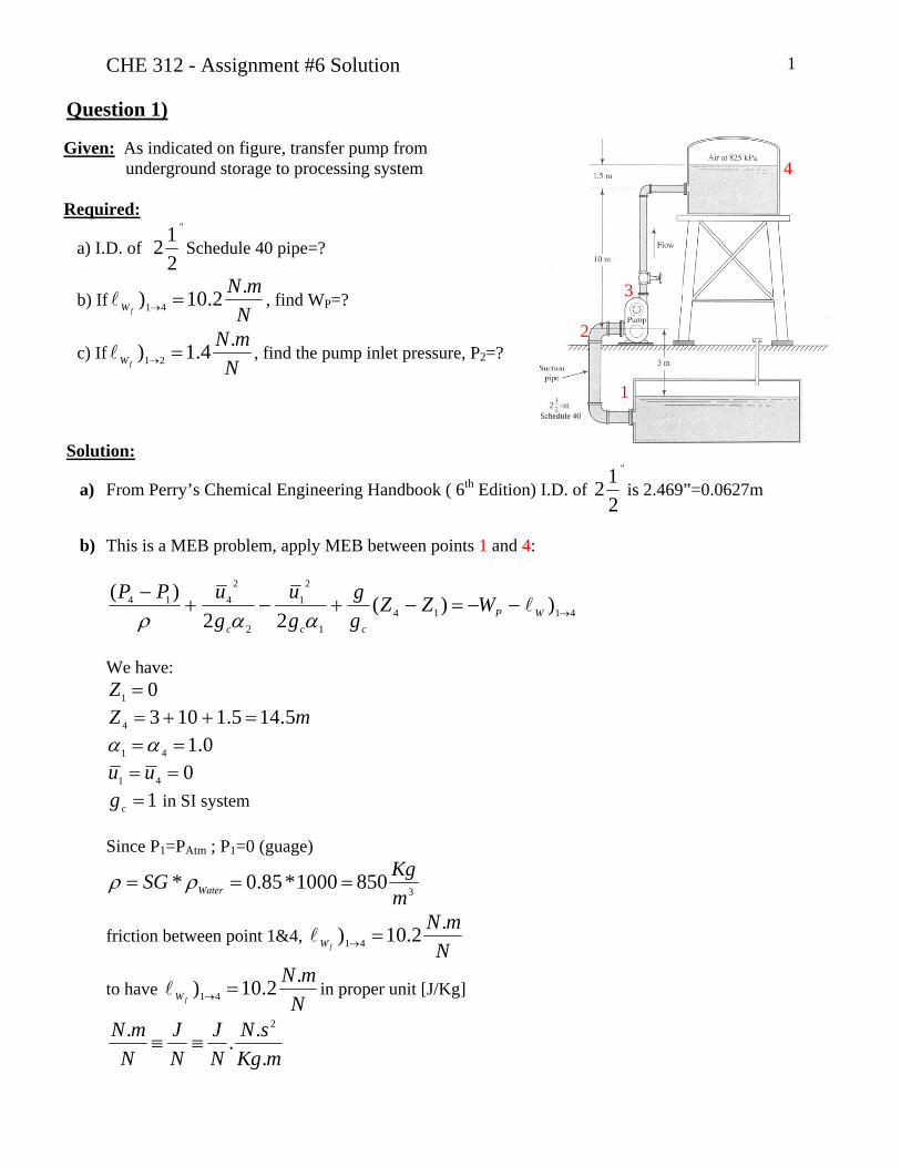
Question 1)
Given: As indicated on figure, transfer pump from underground storage to processing system
4
Required:
a) I.D. of "
212 Schedule 40 pipe=?
b) IfN
mNfW
.2.10) 41 =→l , find WP=?
c) IfNmN
fW
.4.1) 21 =→l , find the pump inlet pressure, P2=?
3 2
1
Solution:
a) From Perry’s Chemical Engineering Handbook ( 6th Edition) I.D. of "
212 is 2.469”=0.0627m
b) This is a MEB problem, apply MEB between points 1 and 4:
41141
21
2
2414 ))(
22)(
→−−=−+−+−
WPccc
WZZgg
gu
guPP
lααρ
We have:
01 =Z mZ 5.145.11034 =++=
0.141 ==αα 041 == uu
1=cg in SI system Since P1=PAtm ; P1=0 (guage)
38501000*85.0*mKgSG Water === ρρ
friction between point 1&4, N
mNfW
.2.10) 41 =→l
to have N
mNfW
.2.10) 41 =→l in proper unit [J/Kg]
mKgsN
NJ
NJ
NmN
.... 2
≡≡
CHE 312 - Assignment #6 Solution 2
So if multiplies tofWl 281.9
smg = ; it becomes:
KgJ
sm
mKgsN
NJg
fWW 1.100)81.9(*).
..2.10(.))2
2
4141 === →→ ll
We wish to solve for WP:
414
41
)()][ gZPPW WP +−
+=− → ρl
5.14*81.9850
1000*)0825(1.100][ +−
+=−KPaWP
KgJWP 1213][ =−
So, to calculate power delivered by pump: ].[.].[ PPP WQWmWPower −=−== ρ&&
)1213(*)60
min1*1000
1*min
840(*)850(3
3 KgJ
SecLitmLit
mKgPower =
WsJPower 1443514435 ==
KWPower 4.14= Answer (b)
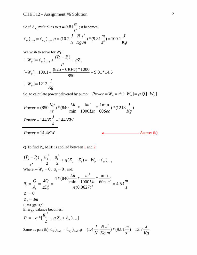
c) To find P2, MEB is applied between 1 and 2:
2112
21
2212 ))(
22)(
→−−=−+−+−
WPWZZguuPPl
ρ
Where: , 0=− PW 01 =u ; and:
smLit
mLit
DQ
AQu 53.4
)0627.0(
)sec60
min*1000
*min
840(*442
3
222
2 ====ππ
01 =Z mZ 32 =
P1=0 (gauge) Energy balance becomes:
]).2
[* 212
22
2 →++−= WZguP lρ
Same as part (b):KgJ
sm
mKgsN
NJg
fWW 7.13)81.9(*).
..4.1(.))2
2
2121 === →→ ll
CHE 312 - Assignment #6 Solution 3 By substitution numerical values into above energy balance:
)(45390]7.134.293.10[*850]7.133*81.92
)53.4([*8502
2 gaugePaP −=++−=++−=
gKPaP .4.452 −= Answer (c)
Question 2)
Given: Plate: WP=10lbf ; 20′′*40′′
sftVP 5.0=
25 .10*6.2
inslb
Oil−=μ
Assume linear oil velocity profile Required:
?=δ , thickness of oil Layer
δ Plate Oil θ=20° y VP
x
Solution: Newtonian law of viscosity for the oil layer:
dydu
yx .μτ = (2.1)
For linear velocity profile VP
PVuy == ,δ y
0,0 == uy x so velocity profile equation becomes:
δδPP V
dyduyVu =⇒= (2.2)
At the plate-oil interface: Wyyx ττδ=
= (2.3)
Using equation (2.1) to (2.3):
δμττ
δ
PWyyx
V==
= (2.4)
We need a value for Wτ , recall that
CHE 312 - Assignment #6 Solution 4
areaSurfaceforceShear
W =τ PW A.τ
20° FGx
Shear force= GxFUsing force analysis: θsin.PGx WF = WP=mg FGy
P
P
P
GxW A
WAF θτ sin.
== (2.5)
psiinin
lbfW 00428.0
)40*20(20sin)10(
==τ (2.6)
Using equation (2.4) to (2.6):
W
PVτ
μδ = (2.7)
sPaftslb
sPaft
inin
slb
fOil .1793.0
)/.(.88.47*144*.10*6.2 22
2
25 == −μ
sm
ftm
sftVP 1524.03048.0*5.0 ==
PapsiPapsiW 51.296895*00428.0 ==τ
Substituting these values to equation (2.7):
mPa
sm
sPa 410*26.9)51.29(
)1524.0(*).1793.0( −==δ
inormm 0365.0926.0=δ Answer
Question 3)
P2 2u 2 Given: Pipe elbow as shown in the figure D1=D2=0.078m y P1=1.17 MPa Q=500 Lit/min water at 65°C P1 1 x
Rx
1u Ry
CHE 312 - Assignment #6 Solution 5 Required: Anchoring forces; Rx, Ry =? Solution:
From table for Water at 65°C: 3984mKg
=ρ
Momentum balance in X-direction: XXXP umRF 1.&−=−
11 uu X = So: 2
1111 uAAPRX ρ+= (3.1) Momentum balance in Y-direction:
222222 uARAPumRF YYYP ρ=+−⇒=+ &
So: 2
2222 uAAPRY ρ+= (3.2) We can assume that P1=P2 ( i.e. neglecting friction losses in the elbow)
using mass balance and since there is not any change in the elbow’s diameter: AQuu == 21
and comparing equation (3.1) and (3.2):
).( 211 uPARR YX ρ+== (3.3)
23
22
21
10*78.44
)078.0(*4
mA
DAAA
−=
==== ππ
sm
mLit
mSec
Lit
AQu 74.1
10*78.4
)1000
*60min*
min500(
23
3
1 ===−
Substituting values into equation (3.3):
NPaRR YX 5610))74.1(*98410*17.1(10*78.4 263 =+== −
KNRR YX 61.5== Answer

CHE 312 - Assignment #6 Solution 6
Question 4)
Given: Water flow system as shown Water Temperature: 20°C h=1m
cmd
cmD
T
e
5.01
==
2 T e 1
Required: Minimum H so that water will start to flow from the lower tank Assumption: Neglect friction losses Solution: * A criteria should be specified that when water will flow from the lower tank? By applying Bernoulli equation from point 1 to venturi throat, T:
0)(22
)(1
21
21 =−+−+
− ZZguuPPT
TT
ρ
01 =Z hZT =
01 =u P1=0(gauge)
02
2
=++ ghuP TT
ρ
ghPu TT −−=ρ2
2
;0≥Tu so: 0≥−−⇒ ghPT
ρ
Or ghPT −≤ρ
(4.1)

CHE 312 - Assignment #6 Solution 7 In other words, water will begin to flow from the lower tank if the pressure at the venturi throat is less than –h meter of water (gauge) We now apply Bernoulli equation from 2 to the exit e:
0)(22
)(2
22
22 =−+−+
− ZZguuPPe
ee
ρ
HZZe −=− 2 02 =u
P2=Pe=0(gauge) So this equation can be written as:
gHuHgue
e 20)(2
2
=⇒=−+ (4.2)
Using Bernoulli equation between Throat T and exit e:
0)(22
)( 22
=−+−+−
TeTeTe ZZguuPP
ρ
0=− Te ZZ Pe=0(gauge) So this equation can be written as:
022
22
=−+− TeT uuPρ
(4.3)
Using Mass balance
)(..T
eeTTTee A
AuuAuAu =⇒= ρρ
Or can be rewritten as: 2)(
T
eeT d
Duu = (4.4)
Substituting equation (4.4) into (4.3):
⎥⎦
⎤⎢⎣
⎡−=−⇒=−+− 1)(
210)(
21
24242
2
T
ee
T
T
ee
eT
dDuP
dDuuP
ρρ (4.5)
Substituting equation (4.2) into (4.5):
⎥⎦
⎤⎢⎣
⎡−−= 1)()2(
21 4
T
eT
dDgHP
ρ (4.6)
CHE 312 - Assignment #6 Solution 8 Combining equation (4.1) into (4.6):
ghdDgH
T
e −≤⎥⎦
⎤⎢⎣
⎡−− 1)( 4
Or:
⎥⎦
⎤⎢⎣
⎡−
≥1)( 4
T
e
dD
hH
Substituting given values for : eT Danddh,
mH 0667.01)
5.01(
14
=
⎥⎦⎤
⎢⎣⎡ −
≥
mH 0667.0min = Answer
For this H value: smu
dDuu
smu T
T
eeTe 57.4)(14.10667.0*81.9*2 2 =⇒=⇒==
Question 5)
Given:
Oil SG=0.93 Q=175 USGPM hpWS 4.28=&
%80=Pη
5.3)5.28)
.8.2)
65
43
21
==
=
→
→
→
W
W
m
fW lb
ftlb
l
l
l
Required:
(a) I.D. for 3 in sch.40 pipe; I.D. for 212 in sch.40 pipe
(b) Determine the power removed from the fluid by the Hydraulic press; ?=HPW&(c) Determine pressures of points 2,3,4,5
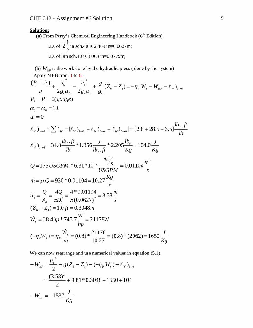
CHE 312 - Assignment #6 Solution 9 Solution:
(a) From Perry’s Chemical Engineering Handbook (6th Edition)
I.D. of 212 in sch.40 is 2.469 in=0.0627m;
I.D. of 3in sch.40 is 3.063 in=0.0779m; (b) is the work done by the hydraulic press ( done by the system) HPW Apply MEB from 1 to 6:
61161
21
6
2616 ).)(
22)(
→−−−=−+−+−
WHPSPccc
WWZZgg
gu
guPP
lηααρ
00.1
)(0
1
61
16
=====
u
gaugePPαα
KgJ
Kglb
ftlbJ
lbftlb
lbftlb
m
f
fW
fWWWWW
0.104205.2*.
356.1*.
8.34)
.]5.35.288.2[])))[)
61
65432161
==
++=++==
→
→→→→ ∑
l
lllll
sm
USGPMs
mUSGPMQ
33
5 01104.010*31.6*175 == −
sKgQm 27.1001104.0*930. === ρ&
sm
DQ
AQu 58.3
)0627.0(01104.0*44
2266
6 ====ππ
mftZZ 3048.00.1)( 16 ==−
WhpWhpWS 211787.745*4.28 ==&
KgJ
mWW S
PSP 1650)2062(*)8.0(27.10
21178*)8.0()( ====−&
&ηη
We can now rearrange and use numerical values in equation (5.1):
KgJW
WZZguW
HP
WSPHP
1537
10416503048.0*81.92
)58.3(
)).()(2
2
6116
26
−=−
+−+=
+−−−+=− →lη

CHE 312 - Assignment #6 Solution 10 Or
KgJWHP 1537=
WWmW HPHP 15800)1537(*)27.10( === &&
Answer(b) KWWHP 8.15=&
Or hpWHP 2.21=&
(c) We use a series of MEB’s to obtain: P2, P3, P4, P5; all the pressure given as KPa & psig - For P2: MEB between 1 & 2:
2112
21
2212 ))(
22)(
→−=−+−+−
WZZguuPPl
ρ
0)(0
1
1
==
ugaugeP
sm
DDuu 32.2)
0779.00627.0(58.3)( 22
2
662 ===
mftZZ 219.14)( 12 ==−
KgJ
Kglb
ftlbJ
lbftlb
m
f
fW 37.8205.2*
.356.1*
.8.2) 21 ==→l
So substituting these numerical values into MEB:
PaKPaP
10001*]219.1*81.9
2)32.2(37.8[*930
2
2 −−−=
psigorgKPaP 1.3.4.212 −−= Answer(c)
- For P3: MEB between 2 & 3:
SP WZZguuPP .)(22
)(23
22
2323 η
ρ−=−+−+
−
]22
.[2
32
223
uuWPP SP −+−+= ηρ
All values are known except P3

CHE 312 - Assignment #6 Solution 11
KgJW
smu
smu
gKPaP
SP 1650.
58.3
32.2
.4.21
3
2
2
=−
=
=
−=
η
PaKPaP
1000*]
2)58.3(
2)32.2(1650[*9304.21
22
3 −++−=
psigorgMPaorgKPaP 219.51.1.10*51.1 3
3 = Answer(c) - For P4: MEB between 3 & 4:
4334
23
2434 ))(
22)(
→−=−+−+−
WZZguuPPl
ρ
43
33 .10*51.1
uugKPaP
==
0)( 34 =− ZZ
KgJ
Kglb
ftlbJ
lbftlb
m
f
fW 21.85205.2*
.356.1*
.5.28) 43 ==→l
MEB becomes:
4334 ). →−= WPP lρ So substituting these numerical values into MEB:
PaKPaP
10001*)21.85(*93010*51.1 3
4 −=
psigorgMPaorgKPaP 207.43.1.10*43.1 3
4 = Answer(c) - For P5: MEB between 5 & 6:
6556
25
2656 ))(
22)(
→−=−+−+−
WZZguuPPl
ρ

CHE 312 - Assignment #6 Solution 12
65
6 0uu
P==
mftZZ 3048.01)( 56 −=−=−
KgJ
Kglb
ftlbJ
lbftlb
m
f
fW 46.10205.2*
.356.1*
.5.3) 65 ==→l
MEB becomes:
65565 ))()0(
→−=−+−
WZZgPl
ρ
So substituting these numerical values into MEB:
PaKPaP
10001*))3048.0(*81.946.10(*9305 −+=
psigorgKPaP 01.1.95.65 = Answer(c)
University of Alberta Department of Chemical and Materials Engineering
ChE 312 Fluid Mechanics Assignment #7
23 - 30 Oct. 2006
Questions Notes Seminar #7 Q2 Will be worked in seminar
Assignment #7 Q1, Q3 Due 2:00pm, Mon. 30 Oct. 2006 Question 1 (15 marks) A new technologist, Moe Szlak, has been assigned to work with you on a big pipeline design project. The line is to transport partially refined crude oil from Ft. McMurray to Edmonton.
(a) Moe says his specialty is determining viscosity using a capillary viscometer. Read P1.36 in your text book and watch video V1.3 (or find another source of information) and then describe the measurements Moe must make in order to determine the fluid viscosity using a capillary viscometer.
(b) In your textbook (p. 316), the Hagen-Poiseuille Equation is written, for inclined flow, as:
( ) 4P gsin DQ
128 Lπ ∆ − ρ θ
=µ
,
where θ is the angle of inclination of the tube. Assuming that, for a capillary viscometer, ∆P = 0 and θ = -90º (i.e. vertical, downward flow), find an expression for K (where ν = K·t).
(c) Moe tells you that he obtained a kinematic viscosity of 7.895 x 10⁻⁵ m2/s, and that the oil density was found to be 760 kg/m3. Since this is an important project, you decide that a single point measurement of viscosity isn’t adequate. You ask Moe to determine the oil viscosity using a tube viscometer (D = 37.8 mm). The data he collects are shown below. Answer the following questions: (i) Which data points would you reject? Why? (ii) Which data points would you ask Moe to replicate? (iii) Based on your analysis, is the oil a Newtonian fluid?
(d) Determine the viscosity of the oil. Ignore the rejected data points and those that Moe is conducting repeat runs for.
Moe Szlak’s tube viscometer data:
Q L/min 33.7 61.3 90.9 121.2 151.5 202.0 249.1 299.6 343.4-dP/dx kPa/m 0.321 1.181 1.670 2.223 3.056 3.582 4.492 6.177 10.150
ChE 312 Assignment #7 23 Oct.-30 Oct. 1

Question 2 (E7.2, G&G) The suggestion is made that the standpipe system shown in the adjacent figure be used as a viscometer.
(a) Evaluate this proposal. D
H
d
L
(b) Assume the system has the following characteristics: H = 304.8 mm; ρ = 860 kg/m3; D = 172 mm; d = 3.175 mm; L = 1219 mm. The flow rate is measured to be 0.296 L/min. Find the viscosity of the fluid.
Question 3 (Based on Text P1.39) (15 marks) A sample of blood is tested in a suitable viscometer. The data obtained from the viscometer tests are shown in the table (below), where shear stress, τ, was determined as a function of shear rate, du/dy.
(a) Based on the data given, determine if the blood is a Newtonian or non-Newtonian fluid. Explain and show clearly how you arrived at your answer.
(b) Moe tests a sample of the blood in his capillary viscometer and determines the blood viscosity. Is this an appropriate method for determining the viscosity of this particular sample? Why or why not?
(c) Suggest one reason why it might be advantageous that blood has this specific flow behavior.
Blood sample viscometer data: τ (Pa) 0.04 0.06 0.12 0.18 0.30 0.52 1.12 2.10 du/dy (s-1) 2.25 4.50 11.25 22.5 45.0 90.0 225 450
ChE 312 Assignment #7 23 Oct.-30 Oct. 2
CHE 312 - Assignment #7 Solution 1
Question 1)
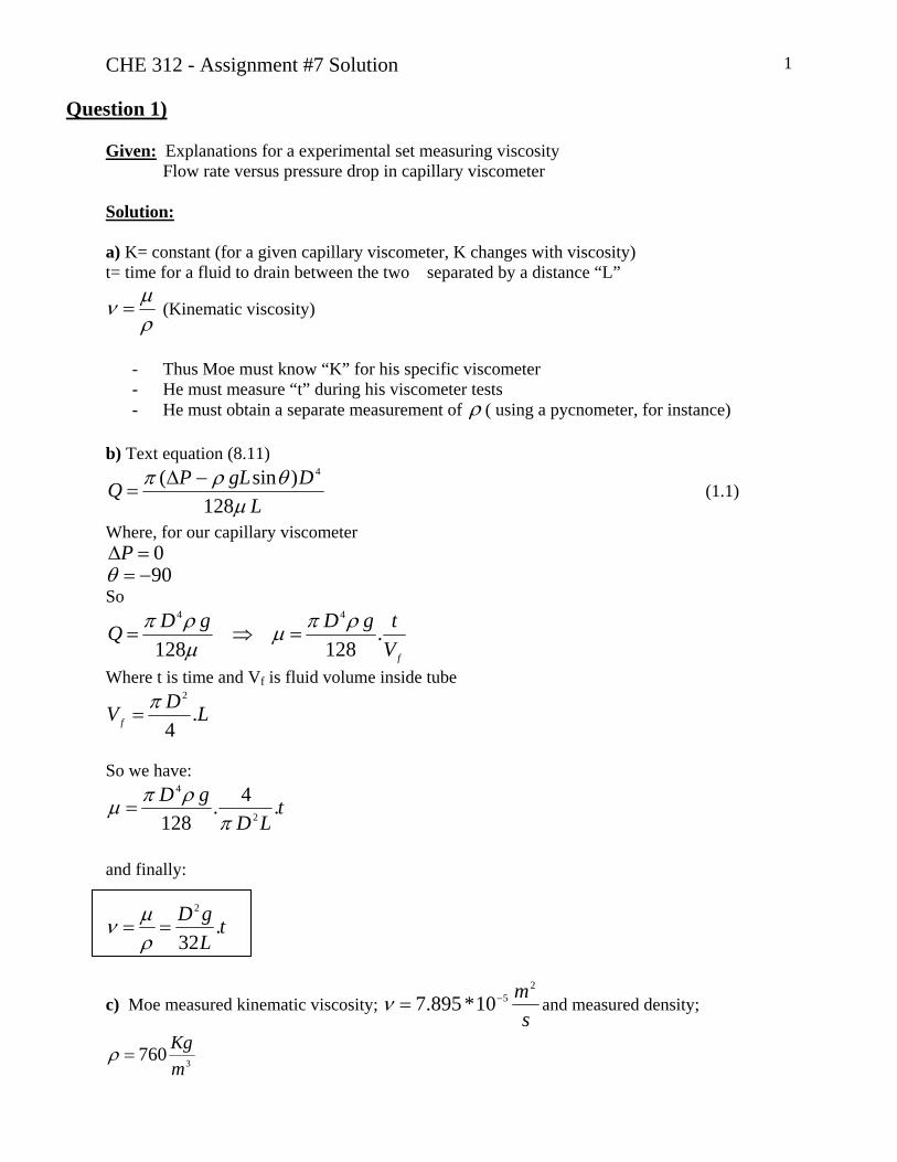
Given: Explanations for a experimental set measuring viscosity Flow rate versus pressure drop in capillary viscometer Solution: a) K= constant (for a given capillary viscometer, K changes with viscosity) t= time for a fluid to drain between the two separated by a distance “L”
ρμν = (Kinematic viscosity)
- Thus Moe must know “K” for his specific viscometer - He must measure “t” during his viscometer tests - He must obtain a separate measurement of ρ ( using a pycnometer, for instance)
b) Text equation (8.11)
LDgLPQ
μθρπ
128)sin( 4−Δ
= (1.1)
Where, for our capillary viscometer 0=ΔP 90−=θ
So
fVtgDgDQ .
128128
44 ρπμμρπ
=⇒=
Where t is time and Vf is fluid volume inside tube
LDVf .4
2π=
So we have:
tLD
gD .4.128 2
4
πρπμ =
and finally:
tLgD .
32
2
==ρμν
c) Moe measured kinematic viscosity; s
m2510*895.7 −=ν and measured density;
3760mKg
=ρ

CHE 312 - Assignment #7 Solution 2
Step 1: Convert Q versus dxdP
− to SI units asmPa
sm &
3
Step2: Use Moe’s data for density and viscosity to determine the Reynolds number for each data point.
mmLmmD
12198.37
==
sPa.06.0760*10*895.7. 5 === −ρνμ
Reynolds number is calculated by:
μρ Du
=Re
2
4DQu
π=
So Reynolds number can be rewritten as:
μπρD
Q4Re =
Using this equation for each data on the given table, Reynolds number is calculated for each point
Q -dP/dx Q -dP/dx Re L/min kPa/m m3/s Pa/m 33.7 0.321 0.000561 321 239 61.3 1.181 0.001021 1181 436 90.9 1.670 0.001515 1670 646
121.2 2.223 0.002020 2223 862 151.5 3.056 0.002525 3056 1077202.0 3.582 0.003367 3582 1436249.1 4.492 0.004152 4492 1772
299.6 6.177 0.004994 6177 2131343.4 10.150 0.005723 10150 2442
Re>2100
The calculated Reynolds number using measured kinematic viscosity by Moe shows two last
points with Q=299.6 and Q=343.3 ⎥⎦⎤
⎢⎣⎡minLit
could be rejected in further study.
Step3: Plot the given data: dxdP
− in ⎥⎦⎤
⎢⎣⎡
mPa
versus Q in ⎥⎦
⎤⎢⎣
⎡s
m3

CHE 312 - Assignment #7 Solution 3
Pressure drop versus flow rate; All Moe's data
0
2000
4000
6000
8000
10000
12000
0 0.001 0.002 0.003 0.004 0.005 0.006 0.007
Q (m3/s)
- dP/
dx (P
a/m
)
All dataRe>2100
This graph confirms the result is step 2 that we could reject these two point that Re>2100 Step4: Plot the selected data where Re<2100 and use a linear regression with intercept =0
y = 1.0972E+06xR2 = 9.8498E-01
0
500
1000
1500
2000
2500
3000
3500
4000
4500
5000
0 0.0005 0.001 0.0015 0.002 0.0025 0.003 0.0035 0.004 0.0045
Q (m3/s)
- dP/
dx (P
a/m
)
Re < 2100
Linear (Re < 2100)
Based on the graph, I would ask Moe to repeat tests for point inside green circles: Q=33.4 and
Q=151.5 ⎥⎦⎤
⎢⎣⎡minLit

CHE 312 - Assignment #7 Solution 4 The oil is undoubtedly a Newtonian fluid. Step5:
- Ignore the above mentioned points in step 4 - Use a linear trend line on remaining points, with y-intercept=0
The regression result is as follow: With these two data: and 610*0972.1== mSlope 98498.02 =R (shown on the figure) Without these two data: 610*082.1== mSlope and 99844.02 =R On the other hand according to equation (1.1):
QDL
P )128( 4πμ
=⎟⎠⎞
⎜⎝⎛ Δ−
)128( 4Dm
πμ
=
So: 128
10*082.1*)10*8.37(*128
6434 −
==ππμ mD
sPa.0542.0=μ
Answer (c)
Question 2)
Given: As indicated on figure, Standpipe system
min296.0
860
1219175.3
1728.304
3
LitQ
mKgmmLmmd
mmDmmH
=
=
====
ρ
1 4 2 3
Required: a) Can this system be used as a viscometer? b) If it does, using given values, find fluid Viscosity, ?=μ

CHE 312 - Assignment #7 Solution 5
Solution: a) Some simplification assumption should be done:
- From 1 to 2: Assume ideal flow ( friction losses is zero) - From 2 to 3: Friction losses are important - Flow regime in capillary tube is assumed to be laminar - Neglect entrance effects ( losses at point 2 is negligible) - Assume fluid density is constant - Velocity profile at 2 is same as velocity profile at point 3 ( means flow is fully developed) - D>>d, ( so 01 ≈u )
Apply Bernoulli equation between point 1 and 2:
0)(22
)(12
21
2212 =−+−+
− ZZguuPPρ
HZZ −=− 12 01 =u
2...
22
12
uHgPP ρρ −=− (2.1)
Apply Hagen-Poiseuille Equation between point 2 and 3:
⎥⎦⎤
⎢⎣⎡ Δ−=
LPdQ
μπ128
4
Where 23 PPP −=Δso:
432
128d
LQPPπμ
=− (2.2)
Note that both point 1 and 3 is to atmosphere, so 31 PP = .Combining equations (2.1) and (2.2):
2...128 2
24
uHgd
LQ ρρπμ
−= (2.3)
We know:
22
4dQ
AQutube π
== (2.4)
Combining (2.3) and (2.4):
224 )4.(
21..128
dQHg
dLQ
πρρ
πμ
−=
or:
LQ
LQHgd
πρρπμ
16128..4
−=

CHE 312 - Assignment #7 Solution 6 So if the assumptions are valid, this system can be used to measure viscosity.
b) Using obtained equation in part (2) and numerical values viscosity can be calculated:
In SI system: s
mLit
mLitQ3
63
10*933.4sec60
min*1000
*min
296.0 −==
Substituting into obtained equation, we have:
219.1*1610*933.4*860
10*933.4*219.1*1283048.0*81.9*860*)10*175.3( 6
6
43
ππμ
−
−
−
−=
Answer (b)
One of the most important assumptions is laminar flow regime in capillary tube. This assumption should be evaluated: To check flow regime, Re number is calculated:
sm
dQu 623.0
)10*175.3(*10*933.4*44
23
6
22 ===−
−
ππ
0011.010*175.3*623.0*860Re
32
−
==μ
ρ du
smPaorsPa .1.1.0011.0=μ
1547Re = This shows laminar flow regime assumption is valid, so obtained value for viscosity is consistent.
Question 3) Given: Blood sample viscometer data:
τ (Pa) 0.04 0.06 0.12 0.18 0.30 0.52 1.12 2.10
du/dy (s-1
) 2.25 4.50 11.25 22.5 45.0 90.0 225 450 Required:
a) is the blood Newtonian or non-Newtonian? b) Is the capillary system appropriate method for viscosity of this system? c) Reason for advantageous of blood behavior
CHE 312 - Assignment #7 Solution 7 Solution:
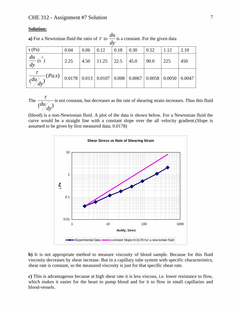
a) For a Newtonian fluid the ratio of τ to dydu
is a constant. For the given data
τ (Pa) 0.04 0.06 0.12 0.18 0.30 0.52 1.12 2.10
dydu
(s-1
) 2.25 4.50 11.25 22.5 45.0 90.0 225 450
).()(
sPady
duτ
0.0178 0.013 0.0107 0.008 0.0067 0.0058 0.0050 0.0047
)( dyduτ
The is not constant, but decreases as the rate of shearing strain increases. Thus this fluid
(blood) is a non-Newtonian fluid. A plot of the data is shown below. For a Newtonian fluid the curve would be a straight line with a constant slope over the all velocity gradient.(Slope is assumed to be given by first measured data; 0.0178)
Shear Stress vs Rate of Shearing Strain
0.01
0.1
1
10
1 10 100 1000
du/dy, 1/sec
τ,Pa
Experimental Data constant Slope=0.0178 for a new tonian f luid
b) It is not appropriate method to measure viscosity of blood sample. Because for this fluid viscosity decreases by shear increase. But in a capillary tube system with specific characteristics, shear rate is constant, so the measured viscosity is just for that specific shear rate. c) This is advantageous because at high shear rate it is less viscous, i.e. lower resistance to flow, which makes it easier for the heart to pump blood and for it to flow in small capillaries and blood-vessels.

University of Alberta Department of Chemical and Materials Engineering
ChE 312 Fluid Mechanics Seminar #8 / Assignment #8
30 Oct. – 06 Nov. 2006
Questions Notes Seminar #8 Q1 and Q2 To be done in seminar
Assignment #8 n/a No Assignment this week Question 1
0
50
100
150
200
250
300
350
400
450
500
0 20 40 60 80 100 120 140 160 180 200
Q, L/min
Pres
sure
rise
, kPa
0
10
20
30
40
50
60
70
80
90
100
Pum
p ef
ficie
ncy,
%
A centrifugal pump transfers water from a large reservoir at atmospheric pressure to a pressurized surge tank. When the water level in the tank is the same as that in the reservoir, the air pressure gauge on the surge tank reads 22 psig and the level is 1 ft. above the bottom of the cylindrical surge tank. Assume you can neglect all friction in the transfer lines. For the pump characteristics shown in the adjacent graph: (a) What is the pump power consumption (in W)? (b) The discharge valve on the surge tank is adjusted until the level rises to 9.5 ft above the bottom of the tank. If the surge tank is 18 ft in height and the air temperature stays constant as the air is compressed, what is the pump power consumption now? Question 2 (Text P5.54) What is the maximum possible power output of the hydroelectric turbine shown in the adjacent figure?
ChE 312 Assignment #8 30 Oct. – 06 Nov. 1

University of Alberta Department of Chemical and Materials Engineering
ChE 312 Fluid Mechanics Seminar #9 / Assignment #9
06 – 15 Nov. 2006
Questions Notes Seminar #9 n/a See separate handout
Assignment #9 Q1, Q2, Q3 Due 14:00 Wed. 15 Nov. Question 1 (Text P8.24) Water flows at a rate of 2.0 ft3/s in an old, rusty p(D = 6 in) that has a relative roughness of 0.010is proposed that by inserting a smooth plastic linwith an inside diameter of 5 in into the old pipe, as shown in the adjacent figure, the pressure dropmile can be reduced. Is it true that the lined pipe can carry the required flow rate as a lower pressure dropthan the old pipe? Support your answer with the appropriate calculations.
ipe . It er
per
Question 2 (Text P8.40) At a ski resort, water at 40ºF is pumped through a steel pipe (D = 3 in) from a pond at an elevation of 4286 ft to a snow-making machine at an elevation of 4623 ft. The flow rate is 0.26 ft3/s. If it is necessary to maintain a pressure of 180 psi at the snow-making machine, determine the horsepower added to water by the pump. Neglect minor losses. The pipe is 2000 ft in length. Question 3 (Text P8.50) Water flows through a pipe (D = 2 in, ε/D = 0.004) at a velocity of 15 ft/s, as shown in the figure (below). The loss coefficient for the exit is 1.0. Determine the height, h, to which the water rises in the piezometer tube.
ChE 312 Assignment #9 06 – 15 Nov. 1

CHE 312 - Assignment #9 Solution 1
Question 1)
Given:
Rusty Pipe D=6”; 01.0=Dε
Lined Pipe D=5”; 0=Dε
(smooth)
sftQ
3
2=
Required:
Is "6"5 ==
⟨DD dx
dPdxdP
satisfied?
Solution: 1 2 Straight Pipe: Use MEB between point 1 and 2:
wSPWZZguuPPl−−=−+−+
− )()(22
)(12
1
21
2
2212 η
ααρ
As we know:
012 =− ZZ
21 uu = 0.121 ==αα
MajorwMinorwMajorww ))) llll =+= ( no minor losses)
0=SW after simplification, MEB reduces to:
Majorw
PP ))( 12 l=−ρ
Or
DLufPP
2)( 2
12 −=−ρ
(1.1)

CHE 312 - Assignment #9 Solution 2 This equation can be written as:
Duf
dxdP
LPP
2)( 2
21 ρ=−=
− (1.2)
For the old, rusty pipe: ( “O” means “Old”) and using equation (1.2):
O
OO
O Duf
dxdP
dxdP
2
2
"6
ρ=−=− (1.3)
For the new, Lined pipe: ( “N” means “New”) and using equation (1.2)
N
NN
N Duf
dxdP
dxdP
2
2
"5
ρ=−=− (1.4)
If
O
N
dxdPdxdP
A)(
)(
−
−= then we want to see if A<1?
Using equation (1.3) and (1.4) definition for A becomes:
2).(.O
N
N
O
O
N
uu
DD
ffA = (1.5)
We know DO, DN and ONON ffuu ,,, must be calculated
sft
DQ
AQu
OOO 19.10
)126(
)2(442
2 ====ππ
sft
DQ
AQu
NNN 7.14
)125(
)2(442
2 ====ππ
Now we are left to find ; where ON ff ,sft
lbm
.10*55.7 4−=μ
54
10*21.410*55.7
)126)(19.10)(4.62(
Re ===−μ
ρ OOO
Du

CHE 312 - Assignment #9 Solution 3 From the Moody diagram:
510*21.4Re =O
01.0=Dε
038.0=⇒ Of
For : Nf
54
10*06.510*55.7
)125)(7.14)(4.62(
Re ===−μ
ρ NNN
Du
From the Moody diagram:
510*06.5Re =N
0=Dε
013.0=⇒ Nf
Using these values and equation (1.5):
854.0)19.107.14).(
56).(
038.0013.0( 2 ==A
Or
ON dxdP
dxdP 854.0=
So, Yes the new pipe has a lower pressure drop ( 85.4% compared to the rusty pipe)
Answer (c)
Question 2) 2
Given: Pump ∇ 1 Pond P2=180 psig T=40°F Elevation of Snow INC=Z2=4623 ft
Snow INC.
Elevation of Pond=Z1=4286 ft

CHE 312 - Assignment #9 Solution 4 P1=0 psig
sftQ
3
26.0=
PipeSteelDftL
"32000
==
01 =u (Large reservoir) Required: pump power, ?=− PW& Solution: Use MEB between point 1 and 2:
wPPc WZZguugPPl−−=−+−+
− ηρ
)(22
.)(12
21
2212
By neglecting minor losses and other simplification, the MEB converts to:
MajorwPC WZZgugP ))(2
.)(12
222 l−−=−++
ρ (2.1)
Where D
LufMajorw 2
)2
2=l (2.2)
we must determine: 2,uf
sft
DQ
AQuPipe
30.5)
123(
)26.0(442
22
2 ====ππ
From appendix B.2; kinematic viscosity of water at 40°F:s
ft.
10*664.12
5−==ρμν
45
22 10*96.766410.1
)123)(30.5(
Re ===−ν
Du
and from table 8.1 for steel pipe: 410*6)
123(
00015.000015.0 −===D
orft εε
From the Moody diagram (text Fig8.10)
410*96.7Re =O 021.0=⇒ Of
CHE 312 - Assignment #9 Solution 5
410*6 −=Dε
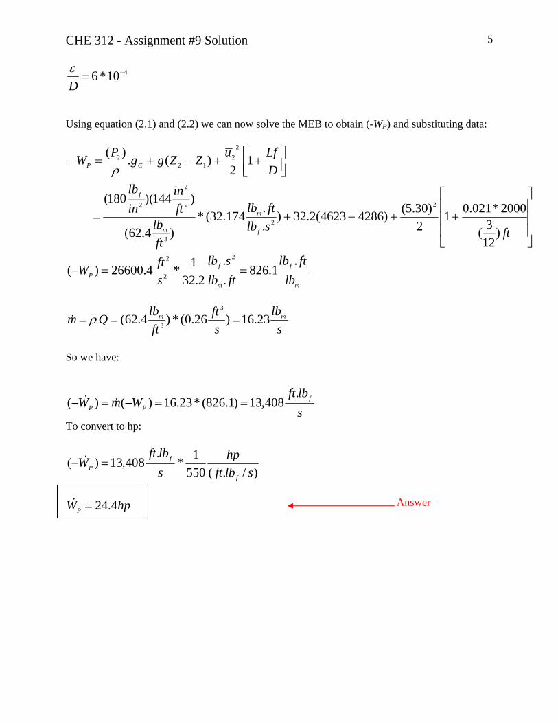
Using equation (2.1) and (2.2) we can now solve the MEB to obtain (-WP) and substituting data:
⎥⎥⎥
⎦
⎤
⎢⎢⎢
⎣
⎡
++−+=
⎥⎦⎤
⎢⎣⎡ ++−+=−
ftslbftlb
ftlb
ftin
inlb
DLfuZZggPW
f
m
m
f
CP
)123(
2000*021.012
)30.5()42864623(2.32)..174.32(*
)4.62(
)144)(180(
12
)(.)(
2
2
3
2
2
2
22
122
ρ
m
f
m
fP lb
ftlbftlbslb
sftW
.1.826
.
.2.32
1*4.26600)(2
2
2
==−
slb
sft
ftlbQm mm 23.16)26.0(*)4.62(
3
3=== ρ&
So we have:
slbft
WmW fPP
.408,13)1.826(*23.16)()( ==−=− &&
To convert to hp:
)/.(5501*
.408,13)(
slbfthp
slbft
Wf
fP =− &
hpWP 4.24=&
Answer

CHE 312 - Assignment #9 Solution 6
Question 3) Given:
D=2 in
004.0=Dε
KL=1.0
h 2 ∇ 8 ft D Water, 15 ft/s 1 8 ft
Required: h=? Solution:
Use MEB between point 1 and 2:
gZZ
gu
gu
gPP Totalw ))(
22)(
12
21
2212 l
−=−+−+−ρ
(3.1)
Where P2=0 ( gauge) Z1=0 Z2=8 ft We know:
22
)))2
12
1 uKD
LufL
MinwMajwTotalw
+=
+= lll
(3.2)
hg
P=
ρ1 (3.3)
So that using (3.2)&(3.3) the MEB (3.1)becomes:
2
21 1
2ZK
DfL
guh L =⎥⎦
⎤⎢⎣⎡ −−+ (3.4)
We need f:
CHE 312 - Assignment #9 Solution 7
54
10*07.210*55.7
)122)(15)(4.62(
Re ===−μ
ρ Du
From the Moody diagram (Fig8.10):
510*07.2Re =
004.0=Dε
029.0=⇒ f
Substituting into equation (3.4):
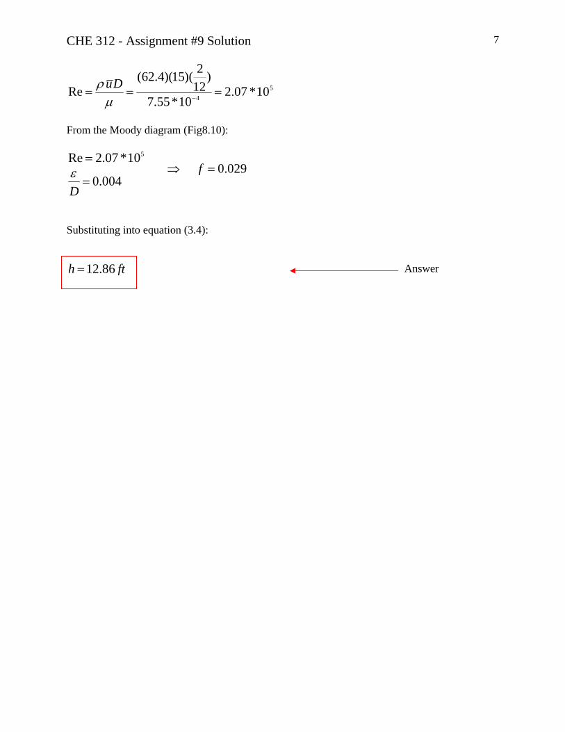
fth 86.12=
Answer
University of Alberta Department of Chemical and Materials Engineering
ChE 312 Fluid Mechanics Assignment #10
13 – 20 Nov. 2006
Questions Notes Seminar #10 n/a No seminar this week
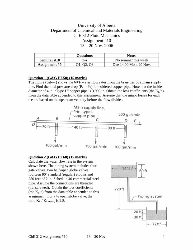
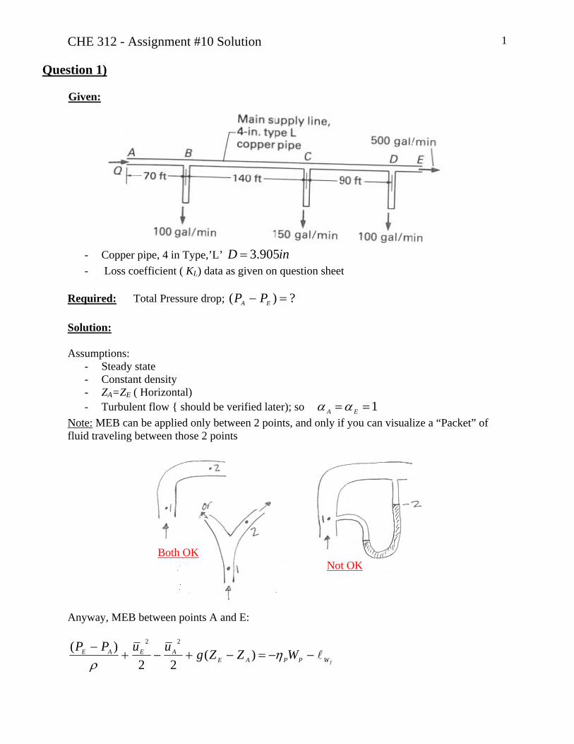
Assignment #9 Q1, Q2, Q3 Due 14:00 Mon. 20 Nov. Question 1 (G&G P7.58) (15 marks) The figure (below) shows the 60ºF water flow rates from the branches of a main supply line. Find the total pressure drop (PA – PE) for soldered copper pipe. Note that the inside diameter of 4 in. “Type L” copper pipe is 3.905 in. Obtain the loss coefficients (the KL’s) from the data table appended to this assignment. Assume that the minor losses for each tee are based on the upstream velocity before the flow divides.
Question 2 (G&G P7.68) (15 marks) Calculate the water flow rate in the system shown here. The piping system includes four gate valves, two half-open globe valves, fourteen 90º standard (regular) elbows and 250 feet of 2 in. Schedule 40 commercial steel pipe. Assume the connections are threaded (i.e. screwed). Obtain the loss coefficients (the KL’s) from the data table appended to this assignment. For a ½ open globe valve, the ratio KL / KL (open) is 2.5.
ChE 312 Assignment #10 13 – 20 Nov. 1
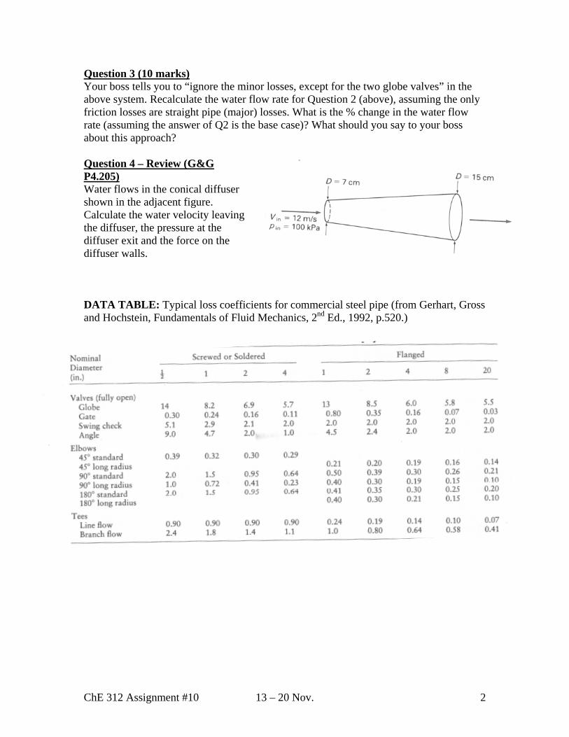
Question 3 (10 marks) Your boss tells you to “ignore the minor losses, except for the two globe valves” in the above system. Recalculate the water flow rate for Question 2 (above), assuming the only friction losses are straight pipe (major) losses. What is the % change in the water flow rate (assuming the answer of Q2 is the base case)? What should you say to your boss about this approach? Question 4 – Review (G&G P4.205) Water flows in the conical diffuser shown in the adjacent figure. Calculate the water velocity leaving the diffuser, the pressure at the diffuser exit and the force on the diffuser walls. DATA TABLE: Typical loss coefficients for commercial steel pipe (from Gerhart, Gross and Hochstein, Fundamentals of Fluid Mechanics, 2nd Ed., 1992, p.520.)
ChE 312 Assignment #10 13 – 20 Nov. 2
CHE 312 - Assignment #10 Solution 1
Question 1)
Given:
- Copper pipe, 4 in Type,’L’ inD 905.3= - Loss coefficient ( KL) data as given on question sheet
Required: Total Pressure drop; ?)( =− EA PP Solution: Assumptions:
- Steady state - Constant density - ZA=ZE ( Horizontal) - Turbulent flow { should be verified later); so 1== EA αα
Note: MEB can be applied only between 2 points, and only if you can visualize a “Packet” of fluid traveling between those 2 points
Both OK Not OK Anyway, MEB between points A and E:
fWPPAEAEAE WZZguuPP
l−−=−+−+− ηρ
)(22
)( 22

CHE 312 - Assignment #10 Solution 2 where
00)(
==−
PP
AE
WZZ
η
and
2.
2.
2.
222CD
DCL
BC
CBL
AB
BAL
WWW
uKDLfuK
DLfuK
DLf
MinorMajorf
→→→⎥⎦⎤
⎢⎣⎡ ++⎥⎦
⎤⎢⎣⎡ ++⎥⎦
⎤⎢⎣⎡ +=
+= lll
Where . From the data table provided, for soldered copper pipe: TEEL KK = 9.0=LK This problem is a CASE 1 problem. We can solve it directly once we know , and
. BA→Re CB→Re
DC→Re Let’s convert to SI units:
CFTmftLmftL
mftLmD
DC
CB
BA
oo 6.156043.279067.42140
34.21700992.0"905.3
==
======
==
→
→
→
smUSGPMQ
smUSGPMQ
smUSGPMQ
smUSGPMQ
DE
CD
BC
AB
3
3
3
3
0316.0500
0379.06000150750
0473.0750100850
0536.0850100150100500
==
==−=
==−=
==+++=
Properties of water at 15.6°C ( Table B.2, p.507 text) sPamKg .0012.0;999 3 == μρ
For calculating Ave. velocities in each mainline section: 232
10*729.74
)0992.0( mA −==π
And μ
ρ uD=Re
sm
AQu
sm
AQu
BCBC
ABAB
12.6
935.6
==
==
sm
AQu CD
CD 904.4==
⇒ 5
5
10*4.50012.0
)12.6)(0992.0)(999(Re
10*1.60012.0
)935.6)(0992.0)(999(Re
===
===
μρμ
ρ
BCBC
ABAB
uD
uD
510*3.40012.0
)089.4)(0992.0)(999(Re ===μ
ρ CDCD
uD

CHE 312 - Assignment #10 Solution 3
sm
AQuu DE
EDE 089.4===
Once we determine Dε
, we can determine the 3 friction factors we need
From table 8.1(text): mmtubingdrawn 0015.0)( =ε ; so
00015.02.99
0015.0==
Dε
From the Moody diagram ( or Churchill or Swamee-Jain equations):
0135.00131.00129.0
===
CD
BC
AB
fff
We now calculate
fWl
2904.4.90.0
)0992.0()43.27)(0135.0(
212.6.90.0
)0992.0()67.42)(0131.0(
2935.6.90.0
)0992.0()34.21)(0129.0(
2
22
⎥⎦
⎤⎢⎣
⎡++
⎥⎦
⎤⎢⎣
⎡++⎥
⎦
⎤⎢⎣
⎡+=
fWl
So
KgJ
fW 5.26671.5538.12237.88 =++=l
We can now solve the MEB to obtain EA PP −
⎥⎦
⎤⎢⎣
⎡ =−=
⎥⎦
⎤⎢⎣
⎡+−=−
5.2662
935.62
089.4999
22)(
22
22
fWAE
EA
uuPP lρ
KPaPP EA 6.250)( =− or in English units psi3.36
Answer

CHE 312 - Assignment #10 Solution 4
Question 2) Given: Piping system as shown
4 × Gate valves; 2 × 50% open Globe valves 14 ×90 Std. elbows 250ft of 2 in Sch.40 pipe 1 ×square-edged pipe entrance, 1 exit
Assume all connections are threaded
1 2
Required: Q=? Solution:
Use MEB between point 1 and 2:
fWSPWZZguuPPl−=−+−+
− ηρ
)(22
)(12
21
2212
Where
Atm
SP
PPPW
uu
=====
21
21
00
η
So:
fWZZg l−=− )( 12
and
2.1424
2Pipe
EXENTELBGlobeGateW
uKKKKK
DLf
f ⎥⎦⎤
⎢⎣⎡ +++++=l
Using the data table provided for 2 inch size:
16.0=GateK 3.179.6*5.2)%50(9.6)( ==⇒= openKopenfullyK GlobeGlobe
95.0=ElbowK

CHE 312 - Assignment #10 Solution 5 Using the textbook ( Figs 8.11, 8.12, for sharp-Edged entrance/Exit)
5.0=ENTK 0.1=ExitK
Finally we convert all values to SI:
mftZZmftL
mSchD
06.67220)(2.76250
0525.0"067.240."2
12 −=−=−==
===
We rearrange the MEB to obtain:
21
21
1424
)(2
⎥⎥⎥
⎦
⎤
⎢⎢⎢
⎣
⎡
+++++
−=
EXENTELBGlobeGate
Pipe
KKKKKDLf
ZZgu
By substituting values:
50145127.36+
=f
uPipe (**)
This is a CASE 2 type problem- we must iterate to find a solution:
1. Write MEB+ simplification: Done 2. Guess f ⇒ 05.0)0( =f
3. From Eqn (**), with ⇒ 05.0)0( =fsmu 276.3)0( =
4. Calculate Re using )0(u :
510*720.1001.0
)0525.0)(276.3)(1000(Re ===μ
ρ Du
And 00086.05.52
045.0==
mmmm
Dε
Using the Churchill Eqn.; 02083.0)1( =f
5. Calculate )1(u using (**) & 02083.0)1( =f ⇒ smu 050.4)1( =
6. smuu 774.0276.3050.401 =−=− too high, Must keep iterate
So we repeat steps 3 to 5 ( as shown below).
CHE 312 - Assignment #10 Solution 6
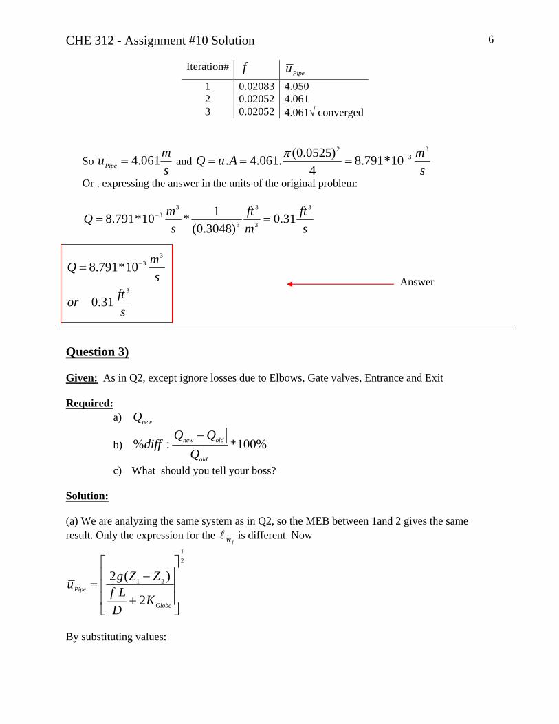
Iteration# f Pipeu 1 0.02083 4.050 2 0.02052 4.061 3 0.02052 4.061√ converged
So smuPipe 061.4= and
smAuQ
33
2
10*791.84
)0525.0(.061.4. −===π
Or , expressing the answer in the units of the original problem:
sft
mft
smQ
3
3
3
3
33 31.0
)3048.0(1*10*791.8 == −
sftor
smQ
3
33
31.0
10*791.8 −=
Answer
Question 3) Given: As in Q2, except ignore losses due to Elbows, Gate valves, Entrance and Exit Required:
a) newQ
b) %100*:%old
oldnew
QQQ
diff−
c) What should you tell your boss? Solution: (a) We are analyzing the same system as in Q2, so the MEB between 1and 2 gives the same result. Only the expression for the is different. Now
fWl
21
21
2
)(2
⎥⎥⎥
⎦
⎤
⎢⎢⎢
⎣
⎡
+
−=
Globe
Pipe
KDLf
ZZgu
By substituting values:
CHE 312 - Assignment #10 Solution 7
6.34145127.36+
=f
uPipe (**)
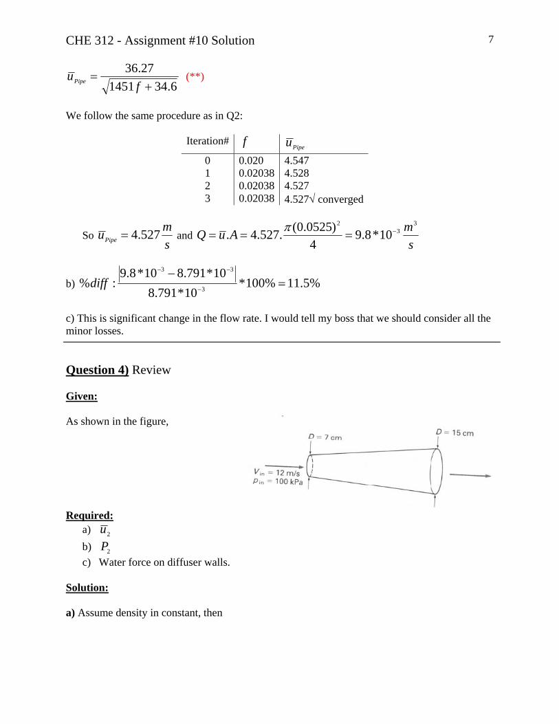
We follow the same procedure as in Q2:
Iteration# f Pipeu
0 0.020 4.547 1 0.02038 4.528 2 0.02038 4.527 3 0.02038 4.527√ converged
So smuPipe 527.4= and
smAuQ
33
2
10*8.94
)0525.0(.527.4. −===π
b) %5.11%100*10*791.8
10*791.810*8.9:% 3
33
=−
−
−−
diff
c) This is significant change in the flow rate. I would tell my boss that we should consider all the minor losses. Question 4) Review Given: As shown in the figure,
Required: a) 2u b) 2Pc) Water force on diffuser walls.
Solution: a) Assume density in constant, then
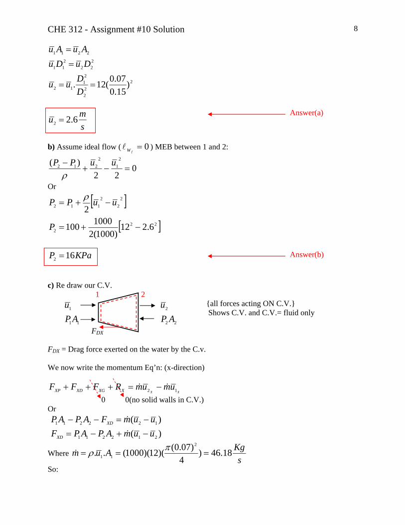
CHE 312 - Assignment #10 Solution 8
222
21
12
222
211
2211
)15.007.0(12. ==
=
=
DDuu
DuDuAuAu
smu 6.22 =
Answer(a)
b) Assume ideal flow ( ) MEB between 1 and 2: 0=
fWl
022
)( 21
2212 =−+
− uuPPρ
Or
[ ]
[ ]222
22
2112
6.212)1000(2
1000100
2
−+=
−+=
P
uuPP ρ
KPaP 162 = Answer(b)
c) Re draw our C.V. 1 2
11
1
APu
22
2
APu
FDX
{all forces acting ON C.V.} Shows C.V. and C.V.= fluid only
FDX = Drag force exerted on the water by the C.v. We now write the momentum Eq’n: (x-direction)
XXumumRFFF XXGXDXP 12 && −=+++
0 0(no solid walls in C.V.) Or
)()(
212211
122211
uumAPAPFuumFAPAP
XD
XD
−+−=−=−−
&
&
Where s
KgAum 18.46)4
)07.0()(12)(1000(..2
11 === πρ&
So:

CHE 312 - Assignment #10 Solution 9
)6.212(*18.46)4
)15.0()(1000)(169()4
)07.0()(1000)(100(22
−+−= ππXDF
09.4345.29868.384 +−=XDF
NFXD 2167−= or positive X direction ( force of the wall on the water NFXD 2167= (The wrong direction was chosen for FXD in the schematic figure) So Force of the water on the walls is 2167N in –X direction
Answer(c)

University of Alberta Department of Chemical and Materials Engineering
ChE 312 Fluid Mechanics Assignment #11
20 – 27 Nov. 2006 Questions Notes
Seminar #11 Q2 To be discussed in seminar Assignment #11 Q1, Q3 Due 14:00 Mon. 27 Nov.
Question 1 (G&G P7.51) (10 marks) A commercial steel flow channel has an equilateral triangle cross section with each side measuring 0.127 m and a length measuring 2.44 m. Water at 15ºC flowing through the channel has a pressure loss of 689.5 Pa. Find the water flow rate (in m3/s). Question 2 (G&G P7.127) Kerosene at 15ºC is pumped through 200 m of smooth 50 cm I.D. pipe at a rate of 10 m3/min from zero velocity, atmospheric pressure and an elevation of 150 m to zero velocity, atmospheric pressure, and an elevation of 155 m. Find the power input to the fluid by the pump. Note: the pipe entrance is square-edged. Question 3 (20 marks) The system (shown here) pumps water from a large tank through a 3 inch Schedule 40 commercial steel pipeline. The water discharges from the line at atmospheric pressure. The flow rate in the line must be maintained at 0.03 m3/s. The performance curve for the centrifugal pump in the system is attached. The system contains a gate valve; all other minor losses can be neglected. For valve positions of (a) full open (KL = 0.255); (b) 50% open (KL = 5.10) and (c) 25% open (KL = 30.6), determine: (i) the pump RPM; (ii) the pump efficiency; (iii) the pump head produced; (iv) the power provided to the pump (in kW). Use the attached pump performance curve. The elevation of the free surface above the datum is 7.5 m. The total pipe length is 31 m.
z1
Question 4 – Review (Text P3.27) A 50 mm diameter plastic tube is used to siphon water from a large tank (see Figure 3.27 in your text, p. 103). If the pressure on the outside of the tube is more than 30 kPa greater than the pressure within the tube, the tube wall will collapse and the siphon will stop. If viscous effects are negligible, determine the minimum value of h allowed without the siphon stopping.
ChE 312 Assignment #11 20 – 27 Nov. 1

Q (L/s)0 10 20 30 40 50 60 70 80
H(m)
0
10
20
30
40
50
60
70
80
Prin
ted
by P
erfo
rman
ce C
urve
s v1
.01.
0075
20/
Nov
/200
6 (4
)
WEIR SLURRY GROUP TYPICAL PUMPPERFORMANCE CURVES
CURVE SHOWS APPROXIMATE PERFORMANCE FOR CLEAR WATER. (To International Test Standard ISO2548 Class C) : For media other than water, corrections must be made for density, viscosity and/or other effects of solids. WARMAN INTERNATIONAL LTD. reserve the right to change pump performance and/or delete impellers without notice. Frame suitability must be checked for each duty and drive arrangement. Not all frame alternatives are necessarily available from each manufacturing centre.
© 1998-2006WARMAN INTERNATIONAL LTD.
WARMAN PUMP IMPELLER: D3147
SIZE FRAME TYPE VANES TYPE IMPELLER MAT'L VANE ø LINER MAT'L
Frame
Rating [kW]
Normal Max.
[r/min]
Metal
Polymer
2750
1985
4/3 AHC CC
D DD
P Q
C
30
CC
55
D
60
DD
110
P
75
Q
150
5 Closed Metal 245 Metal/Polymer
WPA43A01
ISSUEDSEP 1999
MIN. PASSAGE SIZE36
mm SPHERE
GLAND SEALED PUMPR
EF:
TEST
64:
A4-P
-160
4/16
05R
EVI
SIO
N:D
ATA
POIN
T C
OR
REC
TED
LAST
ISSU
E:FE
B 19
88A1
-139
94/1
0
1000
1200
1400
1600
1800
2000
2200
2400
2600
2750r/min
30%
40%
50%
EFFI
CIE
NC
Y
60%
65%
68%
65%
10 m N
PSH
8 m6 m4 m
3 m
ChE 312 Assignment #11 20 – 27 Nov. 2
CHE 312 - Assignment #11 Solution 1
Question 1)
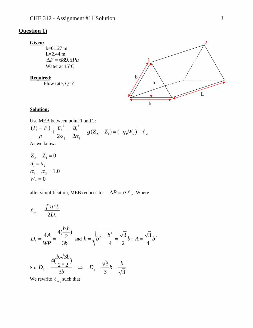
Given:b=0.127 m L=2.44 m
PaP 5.689=∆ Water at 15°C
Required: Flow rate, Q=?
2 1 b h L b
Solution: Use MEB between point 1 and 2:
wSPWZZguuPP−−=−+−+
− )()(22
)(12
1
21
2
2212 η
ααρ
As we know:
012 =− ZZ
21 uu = 0.121 ==αα
0=SW after simplification, MEB reduces to: wP .ρ=∆ Where
hw D
Luff 2
2
=
b
hb
WPADh 3
)2.(44
== and bbbh23
4
22 =−= ; 2
43 bA =
So: 33
33
)2*23.(4 bbD
b
bb
D hh ==⇒=
We rewrite such that fw

CHE 312 - Assignment #11 Solution 2
5
2
2
2
1
38
34.3
2 bLQf
bQ
bLf
f
h
f w
AQu
D
w =⇒
⎥⎥⎥⎥⎥
⎦
⎤
⎢⎢⎢⎢⎢
⎣
⎡
⎥⎦
⎤⎢⎣
⎡=
=
And MEB becomes:
5
2
38
bLQfP ρ
=∆ or 21
5
83
⎥⎦
⎤⎢⎣
⎡∆= P
LfbQ
ρ (*)
This is “Case 2” type problem, so we must iterate:
1) Guess “f ”⇒ 02.0)0( =f
2) Calculate hDε
0006.0127
)045.0(33===
mmmm
bDh
εε
3) Solve for Q using and equation (*) ⇒ 02.0)0( =fs
mQ3
)0( 0100.0=
4) Calculate ; hRe23
4.3
.Reb
bQDu hh µ
ρµ
ρ== ; ⇒
µρb
Qh 3
.4Re =
With s
mQ3
)0( 0100.0= , 4)0( 10*25.9Re =
5) With and 4)0( 10*25.9Re = 0006.0=
hDε
from Moody diagram 022.0)1( =f
6) Using and equation (*) ⇒ 022.0)1( =fs
mQ3
)1( 00959.0=
Continue iterating: 4
)2( 10*82.8Re = ⇒ ⇒ 0215.0)2( =fs
mQ3
)2( 00970.0=
4)3( 10*93.8Re = ⇒ ⇒ 0215.0)3( =f
smQ
3
)3( 00970.0=
smQ
3
00970.0=
Answer

CHE 312 - Assignment #11 Solution 3
Question 2) Given:
Z1=150m; Z2=155m
00
2
1
≈≈
uu
P1=0 ; P2=0 gauge
Required: Power input to the fluid by the pump?
2 5m 1 200m
Solution: MEB between point 1 and 2 ( in “head” from):
LP hhZZg
ug
ug
PP−=−+−+
− )(22
)(12
21
2212
ρ
By simplification, the MEB converts to:
LP hZZh +−= )( 12 Let VuPipe =
⎥⎦⎤
⎢⎣⎡ +++−= ExitENTP KK
DfL
gVZZh2
)(2
12
From Text FIGS 8.11&8.13 ⇒ 0.15.0
==
Exit
ENT
KK
sm
m
DQ
AQVPipe
849.0)5.0(
)sec60
min.min
10(442
3
2====
ππ
We must find f :
From FIG B.2 for Kerosene @ 15°C: s
m2610*9.1 −==
ρµν
And 56 10*23.2
10*9.1)5.0)(849.0(Re ===
−νVD
Note: 0=ε ( Smooth pipe) From Churchill or S-J 0152.0=⇒ f

CHE 312 - Assignment #11 Solution 4
Now using MEB: ⎥⎦⎤
⎢⎣⎡ +++−= ExitENTP KK
DfL
gVZZh2
)(2
12
[ ]mh
h
P
P
278.558.703674.05
15.05.0
)200)(0152.0()81.9(2)849.0(5
2
=+=
⎥⎦⎤
⎢⎣⎡ +++=
From FIG B1: sPa.10*6.1 3−=µ
36
3
84210*9.110*6.1
mKg
==
=⇒=
−
−
ρ
νµρ
ρµν
sKg
sm
mKgQm 33.140)
6010(*)842(
3
3=== ρ
Wsmm
mKgghmW PP 7266)81.9)(278.5(*33.140).()( 23 ===
KWWP 3.7= Answer
Question 3)
Given:
D=3 in Schedule 40 Commercial steel
smQ
3
03.0=
P2=PAtm Z1=7.5m L=31m
1 2 L
%Open KL100 0.255 50 5.10 25 30.6
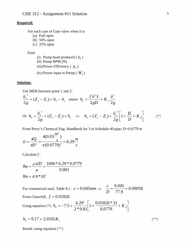
CHE 312 - Assignment #11 Solution 5
Required:
For each case of Gate valve when it is (a) Full open (b) 50% open (c) 25% open
Find:
(i) Pump head produced ( hp ) (ii) Pump RPM (N) (iii) Power Efficiency ( Pη )
(iv) Power input to Pump ( ) SW
Solution:
Use MEB between point 1 and 2:
LP hhZZg
u−=−+ )(
2 12
22 where
guK
gDLufh LL 2
.2
22
+=
Or LP hZZg
uh +−+= )(2 12
22 ⇒ ⎥⎦
⎤⎢⎣⎡ +++−= LP K
DfL
guZZh 12
)(2
212 (*)
From Perry’s Chemical Eng. Handbook for 3 in Schedule 40 pipe: D=0.0779 m
sms
m
DQu 29.6
)0779.0(
)03.0(442
3
2 ===ππ
Calculate f :
510*9.4Re001.0
0779.0*29.6*1000.Re
=
==µ
ρ Du
For commercial steel, Table 8.1 : mm045.0=ε ⇒ 00058.09.77
045.0==
Dε
From Churchill, 01826.0=f
Using equation (*): ⎥⎦⎤
⎢⎣⎡ +++−= LP Kh
0779.031*01826.01
81.9*229.65.7
2
LP Kh 0165.217.9 += (**)
Result: using equation (**)

CHE 312 - Assignment #11 Solution 6
Case Valve Open (%) KL hp=hSys1 100 0.255 9.7 2 50 5.10 19.5 3 25 30.6 71.0
The operating points for each case are marked on the pump performance curve:
sLitQ 30=
Case 1- 100% open
mhP 7.9= rpmN 1100≈ {accuracy: 1050<N<1150}
%5.66=η { accuracy: 66%<η<67%}
KWgQhW PS 3.4
665.0)81.9)(7.9)(03.0)(1000(===
ηρ
Case 2- 50% open
mhP 5.19= rpmN 1450≈ {accuracy: 1420<N<1520}
%5.66=η { accuracy: 66%<η<67%}
KWgQhW PS 6.8
665.0)81.9)(5.19)(03.0)(1000(===
ηρ
Case 3- 25% open
mhP 0.71= rpmN 2625≈ {accuracy: 2610<N<2675}
%56=η { accuracy: 55%<η<57%}
KWgQhW PS 3.37
56.0)81.9)(0.71)(03.0)(1000(===
ηρ
Cases were shown on the pump performance graph by
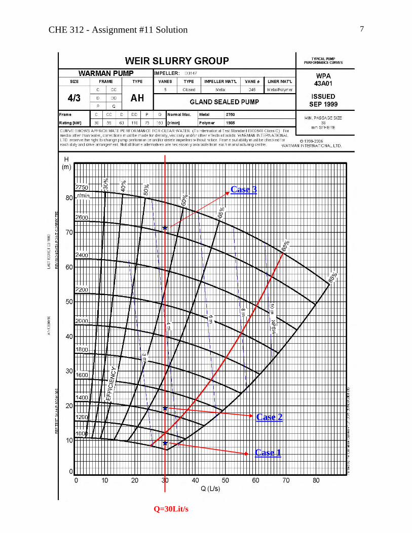
CHE 312 - Assignment #11 Solution 7 Case 3
Case 2
Case 1 Q=30Lit/s
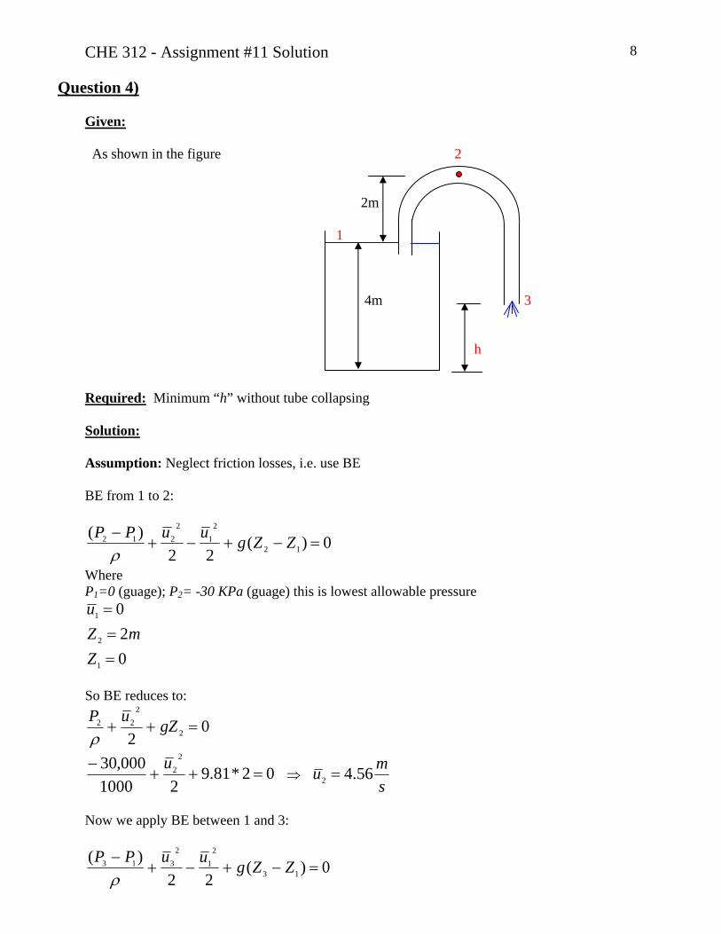
CHE 312 - Assignment #11 Solution 8
Question 4)
Given: As shown in the figure 2 2m 1 4m 3 h Required: Minimum “h” without tube collapsing Solution: Assumption: Neglect friction losses, i.e. use BE BE from 1 to 2:
0)(22
)(12
21
2212 =−+−+
− ZZguuPPρ
Where P1=0 (guage); P2= -30 KPa (guage) this is lowest allowable pressure
020
1
2
1
===
ZmZ
u
So BE reduces to:
02 2
222 =++ gZuP
ρ
02*81.921000
000,30 22 =++
− u ⇒
smu 56.42 =
Now we apply BE between 1 and 3:
0)(22
)(13
21
2313 =−+−+
− ZZguuPPρ

CHE 312 - Assignment #11 Solution 9 Where P1=P3 =PAtm
0)4(
56.4
0
1
3
3
1
=−−=
=
=
ZhZ
smu
u
So 0)0)4((81.92
)56.4(02
=−−−++ h
mh 94.2=

University of Alberta Department of Chemical and Materials Engineering
ChE 312 Fluid Mechanics Assignment #12
27 Nov – 04 Dec. 2006
Questions Notes Seminar #12 Q2, Q3 To be done in seminar
Assignment #12 Q1, Q4, Q5 Due 14:00 Mon. 04 Dec. Question 1 (Text P8.68) (10 marks) Water flows through a venturi meter as shown in the adjacent figure. The specific gravity of the manometer fluid is 1.52. Determine the water flow rate. Question 2 (Seminar) An orifice meter is to be used to measure the flow rate of propyl alcohol (SG = 0.802; ν = 2.57 x 10⁻⁵ m2/s) through a 0.0381 m tube having a wall thickness of 0.0017 m. The expected range of flow rates is 2.5 m3/h to 10 m3/h. Specify the diameter for the orifice if β = 0.70. Determine the range of readings that could be expected if a mercury manometer were used to measure the pressure difference. Use the figure appended at the end of this assignment to determine the orifice discharge coefficient Co. NOTE: For this figure, the Reynolds number is calculated for flow through the orifice! Question 3 (Text P9.35) (Seminar) A 2 in. (diameter) cork sphere (specific weight = 13 lb/ft3) is attached to the bottom of a river with a thin cable, as illustrated in the adjacent figure. If the sphere has a drag coefficient of 0.5, determine the river velocity. Both the drag on the cable and its weight are negligible. Question 4 (G&G P8.58) (10 marks) A domestic engineer dusts off a small table which is 2 ft tall. The dust particles from the table are spherical in shape and have a diameter of approximately 0.001 in. Dust has a density of 90 lbm/ft3. The air temperature in the room is 60ºF. If a dust particle is moving with its terminal velocity the entire fall, how long does it take for the dust particle to settle to the floor? Question 5 (10 marks) Determine the terminal settling velocity for a 0.270 mm sand particle suspended in water at 50ºC. Assume the particle is spherical and the container of water is large. The density of sand can be taken to be 2650 kg/m3.
ChE 312 Assignment #12 27 Nov – 04 Dec. 1

Question 6 – Review Water at 13ºC is withdrawn from a lake and is to be transported by pipeline down to a discharge location located in the valley. The pipeline is constructed from commercial steel and will be 1.5 km in length. The elevation of the lake is 471 m and the discharge location is 315 m (above sea level). The inner diameter of the pipe is 20 cm. A volumetric flow rate of 0.11 m3/s is required. A consultant is asked if a pump is required to produce the required flow, or if a turbine could be installed to generate electric power and maintain the required flow rate. If you are the consulting engineer, what do you tell the client? In either case determine the power (required or produced). Assume a mechanical efficiency of 0.75 for the rotating equipment. Assume the pipe discharges to atmosphere. Figure 12.1. Orifice Discharge Coefficient vs. Orifice Reynolds Number (for Assignment #12, Question 2). Taken from “Fluid Mechanics for Chemical Engineers, 2nd Ed.”, by J.O. Wilkes (Prentice Hall Professional Technical Reference Series, 2006).
ChE 312 Assignment #12 27 Nov – 04 Dec. 2


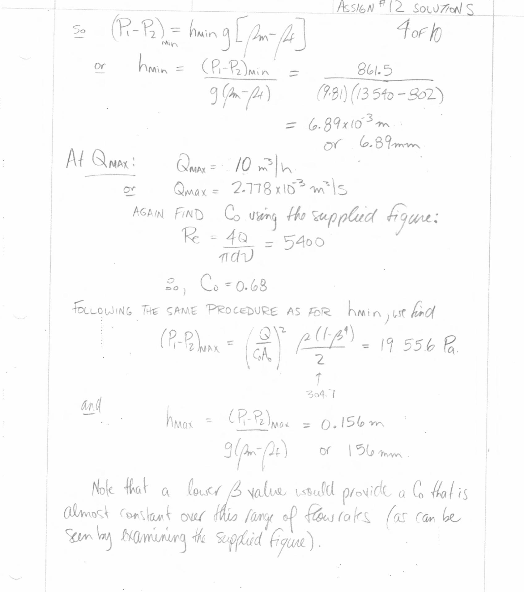


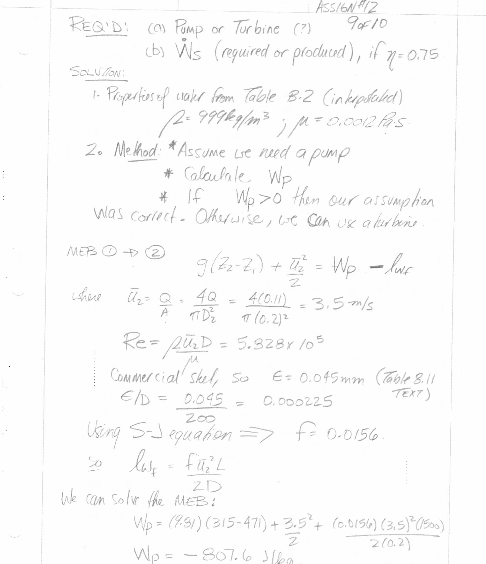


University of Alberta Department of Chemical and Materials Engineering
ChE 312 Fluid Mechanics Seminar #13
04 – 06 Dec. 2006
Questions Notes Seminar #11 Q1, Q2, Q3 To be worked on during seminar
Assignment #11 n/a n/a Question 1 A proposed installation for a centrifugal pump has the following characteristics: Pump suction port = 16 cm Pump discharge port = 10 cm Velocity in discharge pipe = 2.0 m/s Vapour pressure of fluid = 20 kPa Atmospheric pressure = 98 kPa Fluid density = 992 kg/m3
The sump is located below the pump. The upper surface of the fluid in the sump is 3.00 m below the centerline of the suction port. The suction pipe extends 1.5 m below the surface of the sump in normal operation. Losses in the suction pipe, hLp, are 1.5 m. Find the available NPSH. Question 2 (Text P5.23) The hydraulic dredge shown in the adjacent figure is used to dredge sand from a river bottom. Estimate the thrust needed from the propeller to hold the boat stationary. Assume the specific gravity of the sand/water mixture is 1.2. Neglect friction losses in the lines.
Question 3 (Text 3.39) A large open tank contains a layer of oil floating ion water as shown in the adjacent figure. Determine: (a) the height, h, to which the water will rise; (b) the water velocity in the pipe; (c) the pressure in the horizontal pipe. Assume steady, ideal flow.
ChE 312 Seminar #13 04 – 06 Dec. 1