university of alberta...acknowledgement i would like to start by expressing my deepest gratitude to...
TRANSCRIPT

University of Alberta
Experimental and Numerical Analysis of Augmented Locking Plate Fixation
Repair for Proximal Humeral Fractures
by
Farhana Begum
A thesis submitted to the Faculty of Graduate Studies and Research
in partial fulfillment of the requirements for the degree of
Masters of Science
in
Structural Engineering
Civil & Environmental Engineering Department
©Farhana Begum
Fall 2011
Edmonton, Alberta
Permission is hereby granted to the University of Alberta Libraries to reproduce single copies of this thesis
and to lend or sell such copies for private, scholarly or scientific research purposes only. Where the thesis is
converted to, or otherwise made available in digital form, the University of Alberta will advise potential users
of the thesis of these terms.
The author reserves all other publication and other rights in association with the copyright in the thesis and,
except as herein before provided, neither the thesis nor any substantial portion thereof may be printed or
otherwise reproduced in any material form whatsoever without the author's prior written permission.

Examining committee
Dr. Samer Adeeb; Civil & Environmental Engineering
Dr. Jason Carey; Mechanical Engineering
Dr. Marwan El-Rich; Civil & Environmental Engineering
Dr. Martin Bouliane; Division of Orthopaedic Surgery
Dr. Donald Raboud; Mechanical Engineering

Dedication
To Amma.
I know you prayed for me, and I wish you were here to share this moment with!

Abstract
Failure of locking plate fixation due to varus collapse is a common problem for
the elderly population who have osteoporotic bone with comminuted fractures.
However, it is possible to increase the stability and the stiffness of the fixation
system by using intramedullary fibular graft. This study compares the
effectiveness of the augmented versus non-augmented locking plate fixation
under clinically relevant cyclic loading. Nine pairs of cadaveric humeri were
utilized with one side fixated using the augmented system and the other using the
non-augmented one. Analysis of the results revealed that the augmented
constructs can withstand at least three times the number of cycles to failure than
the other one. In addition, finite element models were developed for the quasi-
static loading conditions. The results of the models followed trends similar to the
experimental results and revealed the locations of the stresses distribution within
the constructs.

Acknowledgement
I would like to start by expressing my deepest gratitude to Almighty Allah.
I don’t know how to thank my supervisor Dr. Samer Adeeb, but I do know that I
am a truly lucky person to have had this opportunity to working with him. Samer:
your wonderful personality and continuous encouragement made things so easy
for me!
I was also lucky to have worked with my co-supervisor Dr. Jason Carey, whose
thorough and systematic advice, suggestions and guidance played a major role on
this work.
I feel indebted to the examining committee members for their expert comments
and suggestions which really improved my work.
I would also thank to my colleagues/ friends Muntaseer Kainat, Roxanne Chow
and Nickolaus Gilmour for their support.
Last but not the least; I would like to thank my friends and family for their
support throughout this endeavour. Special thanks to my son, Farhan Zaman, who
showed great patience during my MSc program.
Farhana Begum

Table of Content
Chapter 1 Introduction ............................................................................ 1
1.1 Background of the Study and Problem Statement ............................... 1
1.2 Objective of the Study ........................................................................ 5
1.3 Hypothesis of the Study ..................................................................... 6
1.4 Outline of the Thesis .......................................................................... 6
Chapter 2 Literature Review ................................................................... 8
2.1 Shoulder Joint and Bone .................................................................... 8
2.1.1 Anatomy and Biomechanics of Shoulder Joints .............................. 8
2.1.2 Bone Tissue .................................................................................. 11
2.1.3 Micro, Macro Structure and Function of Long Bones...................12
2.1.4 Osteoporotic Bone and its Mechanical Properties ......................... 14
2.1.5 Repair of Bone Fractures .............................................................. 15
2.2 Proximal Humeral Fractures and Treatment ..................................... 17
2.2.1 Proximal Humeral Fractures ......................................................... 17
2.2.2 Operative Treatment for Shoulder Fractures ................................. 19
2.3 Locking Plate Fixation (LPF) ........................................................... 22
2.3.1 LPF versus Other Operative Techniques ....................................... 22
2.3.2 LPF Complications and the Need for Mechanical Augmetation .... 23
2.4 Biomechanical Analysis of Proximal Humeral Fracture Fixation
Techniques ..................................................................................................... 26
2.4.1 Biomechanical Tests of Non-Augmented Constructs .................... 26
2.4.2 Biomechanical Analysis of Augmented Constructs ....................... 28
2.5 Numerical Modelling ....................................................................... 29
2.5.1 Finite Element Method for Bone and Implant System ................... 30
2.6 Summary ......................................................................................... 31
Chapter 3 Experimental Methodology ...................................................34
3.1 Specimens ........................................................................................ 34
3.2 Specimen Preparation Technique ..................................................... 35
3.2.1 Fracture Simulation and Augmentation ......................................... 35
3.2.2 Locking Plate and Fibular Autograft Fixation ............................... 38
3.3 Tissue Testing Consideration ........................................................... 39
3.4 Experimental Setup .......................................................................... 39
3.4.1 Calculation of Applied Load ......................................................... 39
3.4.2 Support System ............................................................................ 40
3.4.3 Test Procedure and Data Collection .............................................. 42

3.5 Statistical Analyses .......................................................................... 46
3.6 Conclusion ....................................................................................... 47
Chapter 4 Experimental Results and Discussions ...................................48
4.1 Data Collection and Preparation ....................................................... 48
4.1.1 Discarded Specimen ..................................................................... 48
4.1.2 Calculation of Varus Collapse ...................................................... 49
4.1.3 Observed Failure Mechanisms ...................................................... 51
4.1.4 Confidence Level of the Mean Number of Cycles to Failure for
Failed NBP ................................................................................................. 54
4.1.5 Damage per Cycle for both type of Fixation System ..................... 54
4.2 Discussion of Experimental Result ................................................... 56
4.3 Conclusion ....................................................................................... 60
Chapter 5 Development of Finite Element Model ..................................61
5.1 Creating Appropriate Geometry ....................................................... 61
5.1.1 Developing 3D Model of the Humeral Head ................................. 62
5.1.2 Humeral Shaft, Locking Plate Fixation and Fibular Autograft 3D
model Development.................................................................................... 63
5.2 Developing the ABAQUS Model to Simulate the Experiment .......... 65
5.2.1 Importing Parts and Assembly in ABAQUS ................................. 65
5.2.2 Assigning Bone Material Properties and Meshing ......................... 66
5.2.3 Support System, Surface Interactions and Loading ....................... 68
5.3 Results of the Finite Element Analysis and Comparison with the
Experiment .................................................................................................... 70
5.3.1 Expected Stress Development ....................................................... 70
5.3.2 Downward Deformation and Relative Displacement of the Head and
Shaft ..........................................................................................................72
5.3.3 Maximum and Minimum Principal Stresses .................................. 77
5.4 Discussion of the Results ................................................................. 81
Chapter 6 Conclusion and Discussion ..................................................84
6.1 Brief Description of the Experiment ................................................. 85
6.2 Experimental Results and Discussion ............................................... 86
6.3 Finite Element Analysis Findings ..................................................... 88
6.4 Study Limitations ............................................................................. 89
6.5 Recommendation for Future Works.................................................. 91
References ................................................................................................93
Appendix .............................................................................................. 1066

List of Tables
Table 4.1 Failure mechanism of the specimens .................................................. 52
Table. 4.2 Confidence level of the mean number of cycles to failure for failed
NBP .................................................................................................................. 54
Table 4.3 Number of cycles required for one mm damage for each specimen. .. 56

List of Figures
Figure 2.1: Glenohumeral joint .......................................................................... 10
Figure 2.2: Range of movement for shoulder joint ............................................ 10
Figure 2.3: Diagram of a long bone. ................................................................... 13
Figure 2.4: (a) Locking nail; (b) locking plate fixation; (c) blade plate fixation . 21
Figure 2.5: Proximal humeral radiograph of a patient ........................................ 26
Figure 3.1 (a) 10 mm osteonomy created at the surgical neck; (b and c) The fibula
graft inserted into the humeral diaphysis...............................................................37
Figure 3.1 (d and e): Locking plate and screws fixation ..................................... 38
Figure 3.2: Position of the applied cyclic load is located 70 mm away from the
bottom of the third row screws hole of the plate. ................................................ 40
Figure 3.3: The proximal humerus fixated with the implant systems and the test
pot used to create a support like glenohumeral joint. .......................................... 41
Figure 3.4: Synergie 400 testing machine.......................................................... 42
Figure 3.5: Schematic of the testing procedure showing (a) Initial valley load
position of the specimen, (b) Peak load position of the specimen and (c) Valley
load position of the specimen after damage. ....................................................... 44
Figure 4.1: Typical peak load displacement and valley load displacement versus
number of cycles for (a) bone peg specimen, (b) no bone peg specimen.
Horizontal line indicates varus collapse limit ..................................................... 50
Figure 4.2: Failure of the no bone peg specimen. This failure is similar to clinical
failure. ............................................................................................................... 53
Figure 4.3: Maximum Number of loading cycles for all specimens .................... 53
Figure 4.4: Number of cycles and valley load displacement (relative
displacement). The slope of the graph represents the damage per cycle .............. 55
Figure 5.1: Image of Humeral Head in different stages: a) Image from MRI, b)
Generated 3D model in Mimics, c) Edited appropriate surface in Geomagic Studio
12 ...................................................................................................................... 63
Figure 5.2: (a) Extruded humeral shaft from selected contour, 10 mm offset of
fracture surface (b) Cortical and Trabecular bone assembly ............................... 64
Figure 5.3: (a) Locking plate alone (b) Locking plate with fibular autograft ....... 66
Figure 5.4: (a) Cross section of bone; (b) Denser mesh applied around the screw
holes .................................................................................................................. 67
Figure 5.5: Support and loading condition ......................................................... 69

Figure 5.6: (a) Distribution of for the non-augmented implant system; (b) for
the augmented implant system ........................................................................... 71
Figure 5.7: Load vs. downward displacement of the humerus end points obtained
from the finite element models of both types of constructs ................................. 72
Figure 5.8: The deformation of NBP specimen for 100 N load (point A) ............ 73
Figure 5.9: (a) Relative displacement points for experiment (Mathison et al,
2010); (b) FE model .......................................................................................... 74
Figure 5.10: (a) Load vs. relative displacement curve for experiment; (b) Load vs.
relative displacement curve for FE model .......................................................... 75
Figure 5.11: Initial stiffness (slope of load vs relative displacement) of specimens
(experiment) and FE model................................................................................ 76
Figure 5.12: Initial stiffness of BP/NBP ............................................................. 77
Figure 5.13: (a) Maximum principal stress distribution (b) Minimum principal
stress distribution ............................................................................................... 78
Figure 5.14: (a) Direction of maximum principal stress (b) Direction of minimum
principal stress ................................................................................................... 79
Figure 5.15: Load vs. maximum principal stress ................................................ 80
Figure 5.16: Load vs. minimum principal stress ................................................. 81

1
Chapter 1 Introduction
1.1 Background of the Study and Problem Statement
Proximal humeral fracture is a common injury in osteoporotic bone, which
constitutes 10% of all fractures for patients over 65 years old (Baron et al, 1996).
In around 20% of proximal humeral fractures, the bone fragments are
significantly displaced and unstable, requiring operative treatment (Bjorkenheim
et al, 2004; Gerber et al, 2004). Over the years, different types of fixation systems
have been developed to treat unstable and displaced proximal humeral fractures,
such as T-plates, angled plates, cloverleaf plates, k-wires, locked plates and
intramedullary nails (Lever et al, 2008). However, previous studies have found
that the probability of various complications arising from these operative systems
can be as high as 50% (Strohm et al, 2005; Wijgman et al, 2002).
Locking plate fixation is reported to be an improved method for operative
treatment of proximal humeral fractures occurring in osteoporotic bone (Ring,
2007). The locking plate fixation repair technique comprises a lateral plate that is
attached to both the humeral ball and the shaft with special type of locking
screws. Several biomechanical studies have shown that locking plate fixation can
provide more stability and increase the failure load compared to other fixation

2
systems for osteoporotic and non-union fractures (Resch et al, 1997;
Haidukewych et al, 2004; Siffri et al, 2006). However, even the use of locking
plates does not entirely eliminate the possibility of complications, especially for
the elderly. Complications may include intra-articular screw penetration, varus
collapse, and plate buckling or breakage (Egol et al, 2008; Ring, 2007; Sudkamp
et al, 2009). Varus collapse is argued to be due to the supraspinatus and deltoid
contraction during shoulder abduction, especially in situations where the medial
support for the fracture is lacking, i.e., when the medial parts of the humeral head
and the shaft are not in contact (Mathison et al, 2010). Agudelo et al (2007) stated
that without medial support the probability of varus collapse increases and causes
early loss of fixation. These results are supported by the Gardner et al (2007)
study, which shows that proximal humeral fractures repaired without an intact
medial column possess a 29% failure rate (Gardner et al, 2007). Approximately
21 out of 72 proximal humerus fractures treated with locking plate fixation alone
healed with a certain varus deformity after one year (Bjorkenheim et al, 2004).
Frankhauser et al (2005) reported that 3 out of 27 patients had early varus
displacement and 7 patients had early loss of screws. In the majority of the
reported cases, the patients were more than 65 years old. Gardner et al (2007) also
discussed the importance of the medial support and argued that the locking plate
fixation on its own cannot stabilize the medial column of the proximal humerus.
Thus, the existence of a medial column is a key factor for increasing integrity and
stability of the fixation (Gardner et al, 2007). For unstable fractures without a
medial column support and with osteoporotic bone, a mechanical augmentation

3
support is important to construct a stable fixation system (Gardner et al, 2007;
Mathison et al, 2010).
In situations where a medial column support is lacking, mechanical augmentation
can be used to strengthen the construct. In a clinical study, Gardner et al (2008)
first investigated the performance of a fibular allograft as mechanical
augmentation to provide medial support for locking plate fixation with unstable
proximal humeral fractures of osteoporotic bone and found that the augmented
locking plate fixation performs better. Haddad et al (2003) reported that the
fibular allograft has some biological advantages over synthetic alternatives and it
can increase bone stock. Moreover, this type of allograft has the same mechanical
properties of cortical bone. A previous biomechanical study in our research group
has also used the fibular graft as an intramedullary bone peg and compared the
performance of the locking plate fixation with and without the bone peg under the
static loading conditions (Mathison et al, 2010). Mathison et al (2010) observed
that the fixation augmented with fibular grafts were much stronger and stiffer than
the non-augmented ones. However, they noted that both fixations failed at loads
that are higher than those observed in a clinical setting and thus recommended
studying the fatigue behaviour of the constructs under clinically relevant cyclic
loading. A recent biomechanical study tested similar types of constructs for
synthetic bone under the cyclic loading conditions (Osterhoff et al, 2011).
However, Siffri et al (2006) and Zdero et al (2009) argued that the synthetic bone
could not exactly represent the actual one. Another recent study showed that the

4
failure and the stiffness characteristics are different between analogous synthetic
osteoporotic bone and actual human bone when undergoing cyclic torsional
testing (Becker et al, 2011). Hence, this study was initiated with the primary
objective of examining the biomechanical performance of the locking plate
fixation with a fibular graft as the medial column support for repairing proximal
humeral fractures subjected to clinically relevant cyclic loading in cadaveric
specimens.
The second objective of this study was to examine the stresses induced locally
within the construct with and without the augmentation. To achieve this objective,
finite element analysis – a numerical technique to solve the differential equation
of equilibrium in domains with irregular geometries– was used. Finite element
analysis has gained a wide attention in recent years and has been used for many
biomechanical applications including calculating the material properties of bone
and comparing the mechanical behaviour of different bone implant constructs
(Reitbergen, 2004). Finite element analysis has also been used to understand the
reduction in the strength of long bone due to cortical defects (McBroom et al,
1988). Salas et al (2010) developed a finite element model to simulate an
experimental study for comparing two different types of fixation systems and
validated the model by comparing the model results with the experiments. While
finite element analysis has been used for a wide range of problems in
biomechanics, to our knowledge, no study has been performed to understand the
behaviour of augmented and non-augmented locking plate fixation systems. In

5
this study, a finite element analysis model that simulates one previous study
(Mathison et al, 2010) to investigate the behaviour of the same type of constructs
under the ing conditions was created and analyzed to fully understand the
mechanical behaviour of the constructs.
1.2 Objective of the Study
The primary objective of our study is to compare the fatigue behaviour of two
fixation systems under the effect of loading imposed by passive and active
movements during the healing period; namely, locking plate fixation with
intramedullary fibular graft and locking plate fixation without augmentation.
The secondary objective is to use the finite element analysis to examine the
stresses induced under the static loading for the two fixation systems. The
following are the specific aims of our finite element analysis study:
To generate a simplified geometry of the bone and the implant system to
simulate the earlier experimental study conducted by Mathison et al
(2010)
To investigate the relative displacement between the humeral head and
shaft to calculate the initial stiffness of the construct with and without
augmentation and compare the numerical results to those obtained from
the experiment.

6
To examine the maximum principal stresses and observe possible
locations of initial cracks within the construct.
1.3 Hypothesis of the Study
The first hypothesis of our study was that the augmented locking plate fixation
would create a more stable construct and will sustain higher load than the locking
plate fixation alone for clinically relevant cyclic loads.
We also hypothesized that our finite element analysis model is able to mimic the
physical behaviour of the system with and without the augmentation. Then, the
model can be used to understand the stress distribution within the humeral head
and thus explain the experimental observations of the construct failure.
1.4 Outline of the Thesis
This thesis contains six chapters. In the second chapter, an introduction to the
proximal humeral fracture, problems associated with this type of fracture and the
relevant background for this study are presented. The experimental setup is
described in the third chapter and the results of the experimental study are
presented in the fourth chapter. Development of Finite Element Model to simulate

7
the experiment is reported in the fifth chapter of the thesis. Finally, summary of
results and conclusions are discussed in the sixth chapter.

8
Chapter 2 Literature Review
In this chapter, a review of the basic knowledge required to perform this study is
presented. In the first section of this chapter, the anatomy and function of the
shoulder joint and healthy bone tissue are described. The detrimental effect of the
loss of minerals on both the structure and the function of bone are then presented.
In the second section, different types of fractures and available respective
treatments are described. The third and fourth sections describe the locking plate
fixation and the different biomechanical tests available in the literature. Finally,
the finite element analysis technique as a numerical method to solve the
differential equation of equilibrium is presented at the end of the chapter.
2.1 Shoulder Joint and Bone
2.1.1 Anatomy and Biomechanics of Shoulder Joints
The shoulder complex consists of the glenohumeral, acromioclavicular,
strenoclavicular, and scapulothoracic articulation. Due to the combined action of
these articulations, the mobility of shoulder complex is higher than that afforded
by individual articulation (Valle et al, 2001). Flexion and extension, abduction,
and internal-external rotation are the different ranges of motion allowed by the
shoulder complex. Although all articulations are important for the movement of

9
the shoulder, the glenohumeral joint plays the predominant role. Figure 2.1 shows
different parts of glenohumeral joint. Figure 2.2 shows different ranges of
movement of the shoulder joint. This joint is the most mobile and dynamic joint
of the human body. It is a loose ball and socket joint, which allows the arm to
move in circular directions. The ball is the represented by the humeral head. The
socket, on the other hand, is called the glenoid fossa and is covered with hyaline
cartilage. The glenoid fossa is shallow and can contain approximately one third
diameters of the humeral head. The proximal humerus articulates with the glenoid
fossa. The glenohumeral joint capsule has a surface area that is two times the
surface area of the humeral head providing the complex with its wide range of
motion. The capsule also plays an important role for stabilization of the shoulder
by tightening as the arm moves in different positions. Elevation of the arms
depends on the movement of the glenohumeral joint and the scapulothoratic
articulation and their contribution varies for different arm positions. The purely
rotational movement of the glenohumeral joint is caused by the fact that the
humeral head can translate less than 1.5 mm on the glenoid surface during a 30
degree arc of motion (Poppen and Walker, 1976). Capsular, ligamentous and
muscular structures that surround the glenohumeral joint provide further stability
to the movement of the humerus ball relative to the glenoid fossa.

10
Figure 2.1: Glenohumeral joint (Source: The Orthopedic Institute of New Jersey,
Leading MD, Inc., 2009)
Figure 2.2: Range of movement for shoulder joint (Source: Mackenzie, 2004)

11
2.1.2 Bone Tissue
Bone tissue is the major structural component in the musculoskeletal system
(Boyd and Nigg, 2006). It provides support to the body against external forces,
acts as lever systems, transfers forces and also protects vital internal organs.
While the most important structural properties of bone are its strength and
stiffness (Frankel and Nordin, 2001), bone also plays the very important
physiological roles of forming blood cells and storing calcium (Boyd and Nigg,
2006).
Bone tissue differs from other connective tissues due to its hardness and rigidity
and thus it is referred to as the hard tissue. Bone tissue has both organic (collagen
fibres and non-collagenous proteins) and inorganic components (calcium, sodium,
potassium, zinc and magnesium). Inorganic components of bone give it a solid
consistency and make bone hard and rigid, whereas organic components provide
bone with its flexibility (Frankel and Nordin, 2001). Bone normally consists of 60
to 70% of minerals, 5 to 8% of water and approximately 25 to 30% of collagen
fibres.
Bone possesses a dynamic and self-repairing behaviour by which bone can adapt
its density, volume, shape and properties to different mechanical loading and
physiological environments. However, loss of calcium and other minerals lead to
a decrease in the bone mineral density and an increase in its porosity. There are

12
many factors that might lead to the bone losing its dynamic self-repairing
equilibrium and perhaps aging is one of the important causes of the decrease in
bone mineral density, particularly for females (Boyd and Nigg, 2006).
2.1.3 Micro, Macro Structure and Function of Long Bones
The limbs of the human body maintain their shape and rigidity due to long bones.
In particular, the long bone that gives the upper arm its shape, the humerus, is the
focus of this research. At the macro structural level, adult skeleton bones can be
divided into two components which are the cortical and cancellous bones.
Cortical bone or compact bone is a solid and dense material, and it is resistant to
bending. Cortical bone thickness varies according to the different mechanical
requirements for bone. Cancellous bone or trabecular bone has a spongy form
and it contains red bone marrow, a hemopoietic tissue that produces red and white
blood cells and platelets. This type of bone has greater surface area and lower
density. The main shaft of long bones is called the diaphysis which is a hollow
structure surrounding the medullary cavity and filled with yellow fatty marrow.
At the extremities of a long bone are the epiphyses which are covered by articular
cartilage at the joint. The epiphysis is separated from the metaphysis by the
epiphyseal growth plate which is a plate of hyaline cartilage. Metaphyses are the
flared ends of long bone. At the epiphysis, where contact occurs between bones,
the cancellous bone helps distribute load through the bone. Figure 2.3 shows the
diagram of a long bone. Normally cortical bone is the wall of diaphysis and it

13
forms the external surface of the bone. This type of bone is strong and its
thickness varies according to the type and location of bone. Cancellous bone is
found in epiphysis part of long bones (Boyd and Nigg, 2006).
Figure 2.3: Diagram of a long bone (Source: Bone Type,
http://www.shoppingtrolley.net/lesson1-bone-types.shtml).
Long bones are well equipped with a structure that enables the resistance of the
mechanical loads applied on them. Long bones possess adequate strength and a
high modulus of elasticity that enables the long bones to withstand the different in
vivo tension, compression, bending, shear and combined mechanical loading
modes (Frankel and Nordin, 2001). The different components of long bone
possess different mechanical properties according to their role in load support.
Cortical bone is stronger and has higher elastic constants than cancellous bone. In
addition, cortical bone can withstand greater compression stress than tensile
stress. However, muscle contraction can protect the long bone from failure in
tensile force (Frankel and Nordin, 2001).

14
2.1.4 Osteoporotic Bone and its Mechanical Properties
Increased bone fragility due to aging or disease increases the risk of bone
fractures (Boyd and Nigg, 2006). There are several reasons for increased bone
fragility, among them osteoporosis is the most common type of skeletal disease.
Low bone mineral density and deterioration of bone tissue are the main reason for
osteoporosis. The elderly and especially postmenopausal women are more
susceptible to this disease although it can strike at any age.
There are different clinical measures for the extent of osteoporosis. Bone mineral
density (BMD) which is the mass of bone tissue divided by the bulk volume or
tissue level density is the most common measure since it is significantly related to
strength and stiffness of bone (Boyd and Nigg, 2006). It is also possible to detect
osteoporosis by measuring the cortical thickness of the humerus (Bloom et al,
1970; Bloom et al, 1980; Meema et al, 1963). Several studies reported that when
the cortical thickness decreases due to age, it is actually the loss of bone
intracortically and in this way the long bone becomes thinner and more porous
(Atkinson, 1964; Jowsey, 1960). Ring (2007) stated that an osteoporotic proximal
humerus is like an egg shell and in case of operative treatment any screw fixation
is difficult as there is little bone in the centre. Tingart et al (2003) showed that
shoulder specimens of 70 years of age or younger have high combined mean
cortical thickness (4.8 ± 0.96 mm). The thickness for shoulder specimens older
than 70 years, on the other hand, is comparatively low (3.8 ± 0.86 mm) (p < 0.05).

15
This study also showed that the bone mineral density is lesser for specimens older
than 70 years (Student’s t-test, p<0.05).
The strength and stiffness of bone depends on its level of mineralization and thus,
osteoporosis is accompanied by degradation in its elastic modulus and strength.
The elastic modulus of cortical bone has been found to vary between 10-20 GPa
(Frankel and Nordin, 2005; Reitbergen, 2004). The elastic modulus of cancellous
bone varies in a wide range and depends on the bone mineral density (Boyd and
Nigg, 2006) and varies from 0.76 to 10 GPa (Reitbergen, 2004).
2.1.5 Repair of Bone Fractures
High impact forces or stresses that exceed the specific strength of bone and causes
complete or incomplete breaks in the continuity of bone is the main reason of
bone fractures (Levine, 2002; Pathria, 2002). In case of bone fractures, repair
occurs at both the micro structural and the macro structural level (Boyd and Nigg,
2006). At the micro-structural level, “osteoclast” cells are first deployed at the
fracture site to remove older bone. These are then followed by “osteoblast” cells
responsible for laying down the bone matrix in a process termed bone
remodelling. Remodelling plays an important role for repairing bone fractures at
the micro structural level and is constantly taking place to remodel bone tissue. In
the case of large fractures, at the macro structural level, the formation of woven
bone –a randomly oriented newly formed bone tissue– and blood flow into the

16
fracture region (fracture hematoma) are important. The fracture repair depends on
the rapid formation of the woven bone which gives temporary strength and
support to the fracture. In the case of human adults, normally six weeks are
required for the full mineralization of the final callus. The final structure at the
fracture site depends on the orientation of the broken bones and the applied loads
during the healing period (Boyd and Nigg, 2006).
The repair of bone fractures is highly dependent on the patient age. Better and
rapid healing of bone fracture is related to the active healing response of the
periosteum of young patients which is thicker and has a better vascular circulation
than older patients (Buckwalter et al, 1996). However, for older patients with
osteoporotic bone, bone fractures and other orthopaedic complications are
common and thus a longer period of time is required for restoration of functional
competence (Barrios et al, 1993).
Inter-fragmentary movement or relative movement of bone fragments in repaired
fractures is an important factor for bone healing and it is influenced by both the
in-vivo loading during the healing period and the fixation stability (Wehner et al,
2010). Augat et al (2003) reported that a fixation that allows excessive shear load
causes significant delays of healing. On the other hand, Wehner et al (2010)
reported that by increasing the fixation stiffness it is possible to reduce the healing
time by 64%. By increasing the stiffness of the fixator body it is possible to give
mechanical stability to the fracture. The mechanical stability of the fracture is in

17
turn important for its healing. However, the optimal stability is still unknown
(Lienau et al, 2005; Scell et al, 2005). By increasing the fixation stiffness it is
possible to get better results for the treatment of proximal humeral fractures.
2.2 Proximal Humeral Fractures and Treatment
2.2.1 Proximal Humeral Fractures
Humeral fractures are injuries to the upper arm bone and include proximal
humeral fractures, mid shaft humerus fractures and distal humerus fractures.
Proximal humerus fractures occur near the shoulder joint. These fractures are also
known as the anatomical-neck fracture or surgical-neck fracture (Neer, 1970). For
osteoporotic bone, a displaced type of proximal humerus fracture is comparatively
common and is considered a major health issue for its expensive and complicated
treatment.
Proximal humeral fractures are the third most common type of fractures for
people over the age of 65, after hip and distal radius fractures (Baron et al, 1996).
Around 80% of the proximal humerus fractures are stable and minimally
displaced can be treated with non-operative management (Ianotti et al, 2003); the
remaining are described as being badly displaced and unstable fractures that
normally require special treatment, judgment and a complex surgical fixation
(Bjorkenheim et al, 2004; Gerber et al, 2004).

18
Proximal humerus has four major anatomic segments; the head, the lesser
tuberosity, the greater tuberosity and the shaft (Neer, 1970). These parts may be
separated from each other due to fractures of the proximal humerus. Operative
treatment normally required for severely displaced two, three and four-part-
fractures. Kanis et al (2000) showed that risk of shoulder fractures for women is
13.3% and 4.4% for men in Sweden with ages more than 45 years. In the United
Kingdom, the incidence of proximal humerus fractures is 5.7 % and the gender
distribution is 3 males to 7 females (Charles et al, 2006) and the risk increases
with population ages (Palvanen et al, 2006). Palvanen et al stated that one to four
percent women aged over 60 years have a chance of proximal humerus fracture
and this percentage increases gradually.
In the early stages of fracture repair, patient’s arm is immobilized in a sling or
allowed to do some exercises. In those early stages, the forces exerted on the
immobilized humerus can roughly be related to the dimensions and weight of the
immobilized arm. The average weight of the arm is 5.2% of the body weight and
the centroid of the arm is 318 mm from the shoulder joint (Winter, 2005). Forces
created by the supraspinatus on the proximal humeral fracture site in the
immobilized condition of humerus cause 0 to 7.5 Nm of varus bending moment
(Edwards et al, 2006). This moment represents the passive and active motion of
the patient’s arm in the sling during the first six weeks of healing period (Roxanne
et al, 2011). These movements activate the supraspinatus and provide stress to the
fracture site. They are also important for the biological healing and fracture

19
solidifications, and chance of further deformation is quite low for passive
movement of the humerus (Roxanne et al, 2011).
Relative movement of bone fragments plays an important role in fracture repair
and it is highly influenced by the stability of the fixation system in case of
displaced or unstable type of fractures (Wehner et al, 2010). The inter-
fragmentary movement of fracture is certainly affected by the mechanical quality
of bone and for osteoporotic bone it is difficult to provide proper fracture stability
(Barrios et al, 1993). Several studies showed that osteoporotic bone has a good
chance of surgical complications in case of proximal humeral fractures (Neer,
1970; Koval et al, 1996; Williams et al, 1997). Thus, it is important to supply a
system that is adequately stable to allow for healing.
2.2.2 Operative Treatment for Shoulder Fractures
The aim of operative treatment and internal fixation is to give sufficient stability
to the fracture during the healing period. It is difficult to obtain a stable fixation
for osteoporotic bone with displaced type of fractures (Ring, 2007). Reduction of
bone mass and osteoporotic changes may result in high risk of fixation failure,
poor fixation, postoperative loosening of the implants etc. (Hall et al, 1963;
Hawkins et al, 1986). The optimal treatment depends on many factors such as the
bone quality, general health conditions, fracture configuration, activity level, etc.

20
Different types of fixation systems have been developed for treatment of unstable
and displaced proximal humeral fractures; which includes T-plates, fixed angled
blade plates, cloverleaf plates, k-wires, locked plates, intramedullary nails, etc.
(Lever et al, 2008). However, an optimal operative treatment has not been
established yet. Figure 2.4 shows different types of fixation systems that are
frequently used for this type of fracture. Previous studies found that the
probability of complications for operative system varies from 11% to 50%
(Strohm et al, 2005; Wijgman et al, 2002), and avasular necrosis (without proper
blood supply, the bone tissue dies) is very common after both operative and non-
operative treatments (Ring, 2007). Fixed angled blade plate devices are also used
for this type of fixation. Meier et al (2006) reported 22% incidences of blade
penetration into the humeral head in fractures fixated with a 3.5 mm 110 degree
blade plate. In the past several years, 90 degree angled blade plates (Synthes)
have been used for treatment of two and three parts displaced fractures (Siffrri et
al, 2006).
A recent study reported that an overall 33% complication rate was found in the
case of fractures treated with 90 degree angled blade and within these, the most
frequent problem was the extension of the blade into the glenohumeral
articulation (Ring, 2007). The humeral T-plate causes a high risk to the
surrounding soft tissues and screw loosening in the humeral head due to the lack
of angular stability of the plate-screw connection, its large size and its lack of

21
flexibility (Lill et al, 1997). Proximal humeral locking plate system with multiple
fixed angle screw fixation points in the humeral head has recently been used for
osteoporotic bone (Siffri et al, 2006). In the case of osteoporotic bone, loosening
of the screws, avascular necrosis and breakage of the plates are the reported main
forms of fixation failure (Ring, 2007; Tingart et al, 2003). Kitson et al (2007)
stated that the failure of the constructs depend on fracture comminution, soft
tissue stripping, fracture reduction, implant characteristics, bone quality, age,
postoperative rehabilitation program and level of activity.
Figure 2.4: (a) Locking nail (Source: Orthopaedic List.com, 2008) and (b) locking
plate fixation (Siffri et al, 2006) and (c) blade plate fixation (Siffri et al, 2006)
a b c

22
2.3 Locking Plate Fixation (LPF)
2.3.1 LPF versus Other Operative Techniques
As mentioned above, for the treatment of proximal humeral fracture, the use of
locking plate fixation is becoming more popular (Ring, 2007). This type of
fixation is designed for patients with osteoporotic bone and non-union fractures
due to its angular stability and the fact that it can create good bone-implant
interface (Resch et al, 1997). In addition, the plate and the screws perform like a
single unit (Lungershausen et al, 2003). Gardner et al (2006) stated that different
fracture patterns in good quality bone can be treated with the traditional
compression plate. Locking plate can increase load to failure compared to the
unlocked plates due to its multiple points of proximal fixation and also increased
stability of fixation for osteoporotic bone (Haidukewych et al, 2004).
In the case of locking plate fixation, the attachment of the screws to the plate is
rigid and they have fixed angle, thus making the fixation more resistant to failure
by acting as a unit. As a result, the screws and the plate fail simultaneously rather
than individually. This mechanism provides more stability to the osteoporotic
bone where the cortical thickness is thinner. In addition, angular nature of the
plate and screw can resist the cantilever bending stresses and reduces risk of
angular deformation of metaphyseal fractures (A technical overview, AAOS,
2008). The proximal part of the plate consists of at least five locking screws and
additional one or two compression screws (Gardner et al, 2007). The distal shaft
of the plate normally has three or five locking/compression combi-holes including

23
one elongated hole to help in plate positioning. The plates are made of stainless
steel or titanium (Synthes Canada Ltd., 2002).
Lee et al (2009) stated that an intact medial column can increase the pull out
strength of the screws by providing angular stability and ensures a stable fixation
for the humeral head and the surrounding fragments for osteoporotic bone. Siffri
et al (2006) compared blade plate and locking plate fixation in cadaveric
specimens (mean age of 70.0 years) for bending and torsion under the cyclic
loading and found that the locking plate construct provides significantly increased
stability in torsion whereas there is no significant difference between the two
types of fixation in bending. One biomechanical study reported that the locking
plate fixation is more stable as compared to the other available types of fixations
(Lill et al, 2003). Rose et al (2007) reported no postoperative infections, or neuro-
vascular complications, and in a majority of cases the locking plate fixation
achieved fracture reduction, 75% of fractures healed anatomically and they
encouraged improving this technique to get better results (Rose et al, 2007).
2.3.2 LPF Complications and the Need for Mechanical
Augmetation
Several clinical and biomechanical studies have shown that different types of
complications may arise due to the use of locking plate, especially for the elderly
population. These complications may include screws penetration through the
articular surface, varus collapse of the fracture, plate buckling and breakage.

24
These mechanisms of failure normally occur in osteoporotic bone and fractures
with medial metaphyseal comminution (Egol et al, 2008; Ring, 2007; Sudkamp et
al, 2009). Owsley et al (2008) showed that twelve of twenty one patients (more
than sixty years of age) and seven of thirty two patients (less than sixty years of
age) had radiographic signs of complication after six months of operative
treatment. Another clinical study found that after repairing the fracture with
locking plate fixation, three out of thirty six patients (average age 57) had
avascular necrosis; one had a plate breakage and one had a deep infection (Ring,
2007).
Gardner et al (2007) and Lee and Shin (2009) discussed the importance of the
medial support and argued that laterally placed locking plate fixation on its own
cannot support the comminuted fractures where there is a lack of medial column
support. The rate of screw cutting in humeral head cancellous bone, especially in
osteoporotic bone is related to the flexibility of the implant system (Lill et al,
2003). For unstable fractures without a medial column support and with
osteoporotic bone, a mechanical augmentation support medially is important to
construct a stable fixation system (Gardner et al, 2007, Mathison et al, 2010).
Gardner et al (2007) stated that anatomic reduction of medial cortex can create a
stable medial column support for load sharing and minimize the screw bone
surface forces. Agudelo et al stated that without medial support the probability of
varus collapse increases and causes early loss of fixation (Agudelo et al, 2007).
These results are supported by the Gardner et al study, which shows that shoulder

25
fractures repaired without a medial column have a 29% failure rate (Gardner et al,
2007). Different types of techniques are developed to create medial column. A
study showed that the fixation system with calcium phosphate injection can
reduce inter-fragmentary movement and increase the stiffness of the construct
(Known et al, 2002). Several studies used an intramedullary nail to improve the
repair technique of humeral fracture (Kitson et al, 2007; Fouria et al, 2010).
One of the successful mechanical augmentation techniques is the use of a fibular
graft connecting the inside of the shaft to the inside of the humeral head. Gardner
et al (2008) first discussed the fibular allograft as a medial column. Figure 2.5
shows a radiograph of a patient fixated with a locking plate and intramedullary
fibular allograft. The fibula diameter is suitable for using as a medial column of
the proximal humerus. Its size is appropriate for filling the proximal metaphysis
and strong enough for providing additional compressive strength to the medial
column (Gardner et al, 2008). Haddad et al (2003) compared using a metallic nail
to a fibular allograft and stated that the fibular strut has some biological
advantages. Cortical struts are used in bone fixation as a biological plate and can
increase bone stock. Also this type of strut has the same properties as the cortical
bone. However, using fibular graft has several drawbacks (Gardner et al, 2008).
Limited supplies, infection risks and high cost are main disadvantages of using
cadaveric fibular graft.

26
Figure 2.5: Proximal humeral radiograph of a patient (Mathison et al, 2010)
2.4 Biomechanical Analysis of Proximal Humeral
Fracture Fixation Techniques
2.4.1 Biomechanical Tests of Non-Augmented Constructs
Several biomechanical studies have shown that the locking plate fixation can
perform better than the other conventional plates. Weinstein et al (2006) have
shown that locking plate fixation can give better torsional fatigue resistance and
stiffness than blade plates. They applied 0 to 5 N-m external rotational torque to
the humeral head until the head rotate 30 degrees. Another biomedical study
reported that for cyclic loading (120 N) and torque tests (0.4 to 2.5 N-m), locking
plate can perform better than the T-plate (Hessmann et al, 2005). Siffri et al
(2006) performed a biomechanical analysis to compare locking plate fixation and
blade plate for both cadaveric and synthetic specimens. In their study 2 N-m of
axial torque was applied to the humerus (in cadaveric specimens) and found that
the locking plate provided significantly less loosening than the blade plate for
torsional loading. A biomechanical study compared the locking plate and the
Intramedullary fibular
allograft

27
locking nail for proximal humeral fractures and found that the locking nails are
stiffer than the locking plate in cantilever bending for varus, flexion, extension
and torsional forces (Kitson et al, 2007). The author also stated that
intramedullary fixation reduces the lever arm effect of bending around the
fixation device. However, another biomechanical study compared a proximal
humeral intramedullary nail and a locking plate in cadaveric specimens for
bending and torsion and they reported that the locking plate showed significantly
less mean displacement of the distal fragment in bending and less angular rotation
in torsion. The author concluded that the locking plate has better biomechanical
properties than the proximal humeral nail (Edwards et al, 2006). Foruia et al
(2010) also compared locking plates and fixed angle locked nails and found that
for the static loading conditions, locking plate fixation absorbed more energy
before failure and it had better stiffness than the locking nail fixation. Lill et al
(2003) performed a biomechanical study to compare different repair techniques
for proximal humeral fracture. The main objective of his study was to evaluate the
stability of the constructs. The authors applied different loads including cyclic
loading (load level was 300 Nm and 1000 cycles) to compare the constructs. They
found that highest initial stiffness was the reason for early loosening and failure of
the repairing techniques. They concluded that a fixation should be rigid enough to
minimize fracture movement and it should be flexible enough so that it will not
fail very early. They also concluded from their study results that the locking plate
fixation alone is more elastic and it has long term stability which is important for
treatment of osteoporotic bone.

28
2.4.2 Biomechanical Analysis of Augmented Constructs
Clinical and biomechanical studies of proximal humeral fractures show that
augmented constructs are better relative to the non-augmented constructs. In a
clinical study, Gardner et al (2008) investigated the performance of medial
column incorporation in locking plate fixation for unstable proximal humeral
fracture of osteoporotic bone. He suggested that the integrity and stability can be
increased by using fibular graft, and the lack of medial column support is a key
factor for the loss of fixation. A recent biomechanical study also used cadaveric
fibular graft as intramedullary bone peg and compared the performance of locking
plate fixation with and without bone peg for the static loading condition
(Mathison et al, 2010). The constructs were tested in bending and found that the
relative movement between the humeral head and the shaft is lower and the
failure load is higher for the augmented construct. A similar study by Osterhoff et
al (2011) tested the locking plate fixation with and without augmentation where
the intramedullary fibular graft was used for augmentation. They utilized
synthetic osteoporotic bone analogues and tested for varus cyclic loading (load
level was from 50 N to 125 N and 400 cycles) and found that the augmented
construct is stiffer with less inter-fragmentary motion. While Osterhoff et al’s
results are promising, however, recent studies argued that the synthetic bone
cannot represent the actual one (Siffri et al, 2006; Zdero et al, 2009). This is also
supported by another study which compared the synthetic osteoporotic analogues
with the human bone and found different types of failure and stiffness
characteristics (Becker et al, 2011). Embalmed bone, however, is a much more

29
reliable experimental model to test bone tissue. Several studies supported this
observation by showing that embalmed and processed cadaveric bone has
mechanical properties that are similar to those of fresh bone (McElhany et al,
1964). These results support the use of embalmed cadaveric bone in our study to
examine the behaviour of the augmented versus the non-augmented locking plate
fixation under the effect of mechanical cyclic loading.
2.5 Numerical Modelling
A principal objective of this study is to develop a finite element model to simulate
the experiment under the static loading condition, and explore how closely it
represents the actual behaviour of the specimen. This section briefly describes the
terminologies and literatures on finite element analysis relevant to this study.
Finite element method is a numerical approximation technique for finding the
solutions within a mechanical system using partial differential equations of
equilibrium. Due to the complex shape, loading and material behaviour of bone,
the powerful finite element method can help to understand the stress-strain
behaviour (Huiskes and Chao, 1983). Stresses are generated under physiological
loading conditions of bone and the magnitudes and orientation of stresses is not
only dependant on the loading conditions but also on the geometry of structures
and material properties. In addition, the generated stresses depend on the
boundary conditions and interface conditions. In finite element analysis models,
the loading, geometry, material properties, boundary conditions and interface

30
conditions are described mathematically to obtain the resulting stresses within the
modelled part. Huiskes and Chao (1983) mentioned that for fracture fixation and
implant system design, the finite element method is used for pre-clinical
evaluation of the response of the different implant systems. Reitbergen (2004)
also stated that for analysis of bone behaviour in physiological conditions that is
during regular activities, linear elastic analysis is adequate. Nonlinear finite
element analysis is required when bone tissue exceeds the physiological value and
the deformation is large such as during bone remodelling and fracture simulation
where the bone mass changes continuously (Reitbergen, 2004).
2.5.1 Finite Element Method for Bone and Implant System
The finite element method has been widely used to study the mechanical
behaviour of bone alone or with a fixation technique. In the case of osteoporotic
versus healthy bone, Clavert et al (2006) described a finite element analysis
model to determine the strain distribution of the humeral head for young and
osteoporotic bone and found that the stress and deformation development were
large for osteoporotic bone. The method can also be used to study the stresses in
the cementing layers between constructs and bone. In the case of fixation
systems, the finite element analysis method is widely used to calculate the
distribution of stresses within the bone and the construct. Rybicki et al (1974)
performed a finite element analysis for a bone fracture and plate complex. Several
studies used 2D or 3D finite element analysis to understand the interaction

31
between bone and different screws and/or plates (Claes et al, 1982; Woo et al,
1977). To understand the stress distribution inside bone after treatment, the finite
element method has been used for hip joint arthroplasties (Cook et al, 1982;
Skinner et al, 1994) and humeral joint arthroplasties (Orr et al, 1985). Keon Oh et
al (2009) used a finite element analysis (FEA) model to evaluate the effect of a
fracture gap on the stability of a compression plate fixation. In this study the
author also validated the FEA results by a biomechanical analysis and the results
showed slightly greater values at bending angles than the experimental one. A
recent finite element analysis study simulated the experimental study to compare
the mechanical behaviour of the locking plate and intramedullary nail fixation for
distal femoral periprosthetic fracture (Salas et al, 2011). The model was validated
by comparing the load displacement curve of the experiment with the curve
produced by the finite element model. In our current study, we developed a finite
element model to simulate the experimental study for the static loading conditions
and our model results are compared with the experimental ones.
2.6 Summary
While locking plate fixation is an emerging technique for repairing osteoporotic
proximal humeral fractures, several complications, including varus collapse have
been reported in the literature. These complications occur frequently for the
elderly population with osteoporotic bone and comminuted fractures. Bone of
osteoporotic patients have a weak mechanical structure and reduced bone density
which often results in poor performance of the implant system (Hepp and Josten,

32
2007). In addition, medial column support is an important factor to achieve better
treatment for osteoporotic bone fracture with lack of medial column. Thus, a
stable construct providing medial support is a crucial requirement during the
healing period. By using intramedullary fibular graft as a bone peg it is possible to
increase the stability and strength of the fixation to prevent varus collapse and
other possible complications (Gardner et al, 2007). To our knowledge, no
biomechanical studies have compared the locking plate fixation with fibular graft
and locking plate alone for treatment of proximal humeral fracture in cadaveric
bone under clinically relevant cyclic loading conditions. Our hypothesis is that
locking plate fixation with intramedullary column will increase the fatigue life
and durability of the construct. In this study, 10 mm wedge shaped osteotomy will
be created to simulate the clinical situation for displaced proximal humeral
fracture where there is no inherent medial column support. Cyclic load will be
applied by immobilizing the humeral head in a test pot and then applying varus
force to the shaft.
In addition to this biomechanical experiment, a finite element analysis is also
performed for the same two types of constructs but under the static loading
conditions to simulate the previous biomechanical studies performed in our
laboratory (Mathison et al, 2010). Finite element method is a comparatively fast,
low cost and primary investigation method to evaluate a perfect implant system
for fracture repairing (Reitbergen, 2004) and also to augment the experimental
results. In this study, this method will be used to investigate the principal stress

33
distribution in bone and relative displacement of humeral head and shaft for the
static loading condition and then the study results will be compared with the
experimental one. To our knowledge no similar studies have been conducted to
simulate the biomechanical analysis of proximal humeral fracture repaired with
locking plate fixation with or without intramedullary fibular graft.

34
Chapter 3 Experimental Methodology
This chapter describes the specimen preparation, fracture simulation, construction
of implant system, experimental setup of the glenohumeral joint and applied load
simulating the passive movement or small muscle movements of the arms. The
data collection technique and statistical analyses performed in this study are also
described in this chapter. Cadaveric specimens were used for this study. Half of
the specimens were repaired using locking plate fixation alone and the other half
by locking plate fixation with fibular autograft. Ethics application has been
approved to use cadaveric specimens for locking plate fixation of proximal
humeral fracture by the University of Health Research Ethics Board (Bio-
mechanical panel).
1
3.1 Specimens
Nine pairs of embalmed cadaveric specimens were received from the anatomy
department of the University of Alberta for testing. There were total of eighteen
tests for the cyclic loading condition. The mean age of the donors at the time of
death was 87.33 years. Seven of them were female and two were male. Clinically,
fibular grafts are normally used as bone pegs; however, for this study fibular
1 A version of this chapter has been accepted for publication. Chow et al, 2011.
Journal of Shoulder and Elbow Surgery.

35
autografts were used. Our previous study has found that bone mineral density did
not have significant effect on the failure load (Mathison et al, 2010). In addition,
Siffri et al (2006) reported that there is no significant correlation between similar
age group and BMD for relatively small samples of specimens. Bone mineral
density usually decreases with age and the average age of the specimens used in
our study was more than eighty years. For the above reasons, no tests were
performed to determine humeri bone mineral density.
3.2 Specimen Preparation Technique
Specimen preparation was identical to those performed by Mathison et al (2010)
and was performed by a qualified resident surgeon at the University of Alberta
hospital. The cadaveric body was preserved by using an embalming fluid. The
femoral artery was opened and an embalming fluid was injected into the body.
The components of the embalming fluid are 4% phenol, 4% formalin(37%), 8%
glycol, 8% ethyle alcohol(95%) and 76% water. For the purpose of our
experiment, both humeri (from the humeral head to the supracondylar flare) and
an 8 cm segment of fibular diaphysis (narrowest portion) were separated from the
body, and all soft tissues were removed and the bones were rinsed with water. No
other chemicals were used to clean the bone. Humeri were inspected visually to
ensure that there was no major change of normal bony architecture.
3.2.1 Fracture Simulation and Augmentation

36
In each humerus, a 10 mm medially based wedge-shaped osteotomy was created
to simulate a medially comminuted fracture at the level of the surgical neck using
an oscillating saw (Figure 3.1a). It was the most proximal cut of the osteotomy
and was created transversely at the level of the inferomedial margin of the
articular surface of the humeral head. The fibula was isolated randomly from the
left or right side of the cadaver and then decided which side of humerus was
repaired for augmented construction as each fibula was inserted into the ipsilateral
humerus. In case of the augmented humerus, 80 mm fibular graft was inserted as
medially as possible by using 2 mm K-wire to recreate a medial column support.
The fibular graft was then inserted in such a way that 50 mm into the proximal
humeral diaphysis, leaving 10 mm traversing the osteotomy site and 20 mm
would then be impacted into the humeral head (Figures 3.1b and 3.1c). The
fibular grafts were inserted into the proximal humeral diaphysis. When the
diameter of the fibular graft prevented 50 mm of insertion, small amount of outer
cortex was shaved away to prevent splitting of the humeral shaft. Thus the
consistency of the model among all augmented specimens was maintained.

37
(a) (b)
(c)
Figure 3.1 (a): 10 mm osteonomy created at the surgical neck; (b and c): The
fibula graft inserted into the humeral diaphysis

38
(d) (e)
Figure 3.1 (d and e): Locking plate and screws fixation
3.2.2 Locking Plate and Fibular Autograft Fixation
In both humeri, the fracture was secured with a Synthes 3.5 mm LCP stainless
steel proximal humeral plate with three shaft screwholes (Synthes, West Chester,
PA, USA). The plate was placed on the lateral aspect of the humerus and around 8
mm from the superior aspect of the greater tuberosity (Figure 3.1d and 3.1e). It
was temporarily held with a K-wire that was removed after the fixation of the
construct. The diaphysis was secured with a single 3.5 mm cortical screw and two
3.5 mm locking screws which were captured by the fibular graft. Eight 3.5 mm
locking screws were used to fix the proximal fragment of the fracture but the
central humeral head locking hole was not filled with the screw because it might
split the fibular graft. A K-wire was drilled through the locking screw guide until
it minimally penetrated the articular surface to ensure the appropriate length of
screws. The length of the K-wire was measured and a screw 5 mm shorter than

39
the length of the K-wire was used. The length of the screws is important; a larger
patient normally requires longer screws than a smaller patient. In this way the
appropriate length of the screws is ensured without a radiograph.
3.3 Tissue Testing Consideration
As cadaveric specimens were used in this experiment, specimens were preserved
properly and all biohazard and environmental considerations were fully followed.
Risk group of this study was biohazard level 2 as it had moderate individual risk
and low community risk. The experiment was conducted in vitro and a uniaxial
cyclic load was applied by the machine, which provided bending stresses in the
specimens. Human materials were properly treated with respect and dignity. The
biohazard cabinet was used for experimental set up and all waste materials were
kept in the biohazard waste bin. All instruments were properly cleaned with
bleach and methyl alcohol.
3.4 Experimental Setup
3.4.1 Calculation of Applied Load
To understand the fatigue behaviour, specimens were tested under simulated
repeated-type bending cyclic loading. The moment created by the small
movements of the rotator cuff to counteract the weight of the arm during the early
stages of healing when patients are immobilized in a sling or, at most, allowed to

40
begin in a rehabilitation program and pendulum-type exercises was replicated by
applying a specific cyclic load at a precise location on the humerus. The average
weight of a female over sixty five years old in Canada is 62.5 kg (Nutrition
Division, 1953). Based on these data, 10.1 N-m moment is created in the
glenohumeral joint simulating the small movement of the immobilized humerus.
This 10.1 N-m moment at the joint level is equivalent to 7.7 N-m moment applied
at the first support of the distal fragment which is the third screw of the locking
plate (around 20 mm distally from the glenohumeral joint). To get this moment,
110 N vertical load was applied at a distance 70 mm from the bottom of the third
screws (Figure 3.2). This loading is comparable to the loading parameters used by
Edward et al (2006) and Siffri et al (2006).
Figure 3.2: Position of the applied cyclic load is located 70 mm away from the
bottom of the third row screws hole of the plate.
3.4.2 Support System
To simulate the muscular support provided to the ball shaped proximal portion of
the humerus, the cadaveric humeral head was immobilized in a test pot. Denture
Position of applied load

41
resin, a mixture of fast curing orthodontic acrylic resin powder and liquid
(manufactured by Lang Dental Manufacturing Co.), was used to secure the
humeral head in the test pot. Brackets and screws were used with the test pot to
provide support to the resins; it prevented the bone and resins from moving
relative to the test pot. The test pot manufactured for this test was adjustable to
different sizes of the humeral heads. Figure 3.3 shows the test pot that was used
for the test. The joint cavity is cushioned by articular cartilage, which covers the
humeral head and the glenoid fossa and it cannot provide shear support. To
simulate the joint, duct tape and grease were used on the articular surface of the
humeral head so that it could not come in contact with the resin. No resin was
allowed to come in contact with the fracture or the locking plate and screws when
the resin was poured into the pot.
Figure 3.3: The proximal humerus fixated with the implant systems and the test
pot used to create a support like glenohumeral joint.
Test pot Denture
resin
Humerus

42
3.4.3 Test Procedure and Data Collection
The cyclic load testing was performed on a computer controlled Synergie 400
testing machine (MTS System Corporation, Eden Prairie, MN, USA). “Test works
4” software provided with the testing machine was used for test control and data
acquisition. The test pot was fixed to the machine. Figure 3.4 shows the specimen
set up and testing machine used for this test. The cyclic load was applied with a
mechanical test frame to the cadaveric humerus with a displacement rate 600
mm/min. The machine provided the loading and unloading position of the load
frame. For each test, applied load (peak load), zero load (valley load), loading
position (peak load position), unloading position (valley load position) of the
specimen data were recorded for each cycle.
Figure 3.4: Synergie 400 testing machine
Figure 3.5 presents the location of the load frame and specimen at different
loading positions. Initially, the load frame and the humerus are both at position
Load frame

43
Xi with the tip of the load frame touching the top of the sample. This position is
called the initial unloading or valley load position and is shown in Figure
3.5a. During the experiment, the load frame moves vertically down to apply a
force (110 Newton) on the humerus causing a downward displacement to its peak
load position Xp (Figure 5b). The load frame returns vertically upwards to the
position of zero loads. However, after several cycles, the humerus does not fully
return to its initial position due to permanent deformation and this position is
called the valley load position Xv (Figure 5c). The distance between the initial
position and the peak load position is called the peak load displacement Dp and
the distance between the initial position and the valley load position is the valley
load displacement Dv.
Peak load displacement (Dp) = Xi-Xp.
Valley load displacement (Dv) = Xi-Xv
Both displacements are continuously increasing with increasing number of cycles
due to fatigue damage. The data acquisition rate was 100 Hz (cycles/ sec), which
gave the accurate graphical representation of the movement of the specimens’
position for loading (peak load) and unloading (valley load) condition over the
large number of load cycles.

44
Figure 3.5: Schematic of the testing procedure showing (a) Initial valley load
position of the specimen, (b) Peak load position of the specimen and (c) Valley
load position of the specimen after damage.
This process continued throughout the entire testing until the failure of the
construct. The construct was deemed to have failed if either varus collapse
occurred or if the screws came out of the humeral head. In this experiment, varus
collapse was measured by monitoring the loosening of the construct under fatigue
loading. A specimen was deemed to have reached varus collapse when the valley
load position of the specimen after certain load cycles is greater than the initial
peak load position of the specimen at the beginning of the cyclic loading. This
failure criterion was agreed upon after discussion with the qualified surgeon who
frequently performs and assesses this operation. It was noticed during the tests
(b) (a)
(c)
XP
Xi
Test pot
(Fixed Humeral head)
Loading apparatus initial position
(valley load position before damage) Peak load position of loading apparatus
before damage
Dp
Valley load position of loading apparatus
at failure
Dv
Peak load position of specimen
at failure
XV

45
that the bone peg specimens were superior in their resistance to fatigue loading
and thus, the testing was stopped for two specimens when the number of cycles of
the BP specimens reached around 4 times the number of cycles to failure of the
NBP specimen of the same pair. For some specimens, the tests were continued up
to 30 or more thousand cycles. However, considering the biological healing of the
fractures, the first 25 thousand cycles are important as they correspond to the
passive movements of immobilized arms during the first six weeks after
operation. If any implant system withstood more than 25 thousand cycles, it is
assumed that it can provide enough stability during the healing period.
Normally, during the first few weeks after operation, patients are allowed gentle
movements of their arms. It is hoped that after six weeks, the fracture will have
biologically healed and will no longer be relying on the plate construct for its
stiffness and strength. The 25 thousand cycles represents movements of the arm
within the sling post-operatively. In a rehabilitation program, a patient performs
150 repetitions of exercises (scapulothoracic stabilization and pendulum) three
times per day. Patients start this program immediately after operation. This
number additionally provides six cycles per hour for patients who are dependent
on their arm even in an immobilized condition. These activities submaximally
activate the supraspinatus and provide stresses across the plate construct (Chow et
al, 2011).

46
For each specimen, both peak and valley load displacements versus the number of
cycles graphs were prepared. From this graph, cycles to failure were calculated
according to the definition of varus collapse. For each specimen, the data from the
first few cycles (400 to 550 cycles) were neglected to allow for the initial settling
of the test pot and the specimens. From valley load displacement of both bone peg
and no bone peg specimens and the number of cycles graph it is possible to
compare the damage per cycle for the two types of fixation system. The damage
per cycle can be determined by calculating the slope of the graph of the valley
load displacement versus the number of cycles.
3.5 Statistical Analyses
Statistical analyses are performed with the acquired data to determine whether
with bone peg samples are statistically stronger than the non-augmented
counterparts. Hypothesis tests are performed to determine significant difference
between the two types of specimens. In a hypothesis test, there is a null
hypothesis (H0) and it is possible to get statistically significant result by rejecting
the null hypothesis (Montgomery, 2009). Paired t tests are performed to compare
the damage per cycle for the two implant systems (Montgomery, 2009). Paired t-
tests are considered appropriate for this experiment as each pair of cadaveric
specimen had both type of fixation systems. All statistical analyses are performed
using Microsoft Excel.

47
3.6 Conclusion
This chapter described the experimental methodology of the biomechanical
analysis for clinically relevant cyclic load condition. The experimental setup, load
calculations, data collection and the statistical analyses performed in this study
have been described in detail in this chapter. The results and discussion of the
experimental study is presented in the next chapter.

48
Chapter 4 Experimental Results and
Discussions 2
This chapter presents the experimental results and discussions including the
statistical analyses performed in order to justify the conclusions.
4.1 Data Collection and Preparation
4.1.1 Discarded Specimen
Out of ten specimens, nine specimens were included in the study results.
Accidentally, a spike load was applied on one bone peg specimen causing major
damage after three thousand cycles. Whereas in case of the no bone peg specimen
of the same pair, varus collapse occurred after six thousand cycles. For that
reason, this pair of specimen was discarded from the result.
2 A version of this chapter has been accepted for publication. Chow et al, 2011.
Journal of Shoulder and Elbow Surgery.

49
4.1.2 Calculation of Varus Collapse
“Testworks 4” software provided the position of the load applicator throughout
loading and unloading (see appendix). From this position it was possible to
calculate the valley load displacement (full unloading position) and the peak load
displacement (maximum loading position). According to our chosen definition of
varus collapse failure, when the valley load displacement (Dv) of a specimen after
certain load cycles is greater than or equal to the initial peak load displacement
(Dp), significant humerus head fixation loosening was considered to have
occurred in the specimen. Graphs were prepared for the displacement versus the
number of cycles for every specimen. Figure 4.1 shows a typical graph of how the
failure cycles were determined in this experiment for both the bone peg and the no
bone peg specimens. The graph shows the evolution of the test specimen position
during the test; with the damage depicted by the increasing peak and valley load
displacements with increasing number of cycles. From these graphs, it is possible
to determine the number of load cycles required to cause significant loosening
defined by our chosen failure criterion. It can be noted that the first few cycles
(400 to 550 cycles) where the graph is highly nonlinear were neglected to allow
for the initial settling of the test specimens. The slope of the graph of the
displacement versus the number of cycles was much steeper before 400 cycles
than after 400 cycles. The choice of removing 400 to 550 did not have any effect
on the failure of specimens. The bone peg specimens showed superior resistance
to fatigue loading damage. For the pair of specimens shown in Figure 4.1(a) after
30000 cycles the initial peak load displacement (Dp) is greater than the valley load

50
displacement (Dv). Thus, the specimen is deemed to have passed the test without
failure. Figure 4.1(b) however shows that for this particular no bone peg
specimen, significant loosening occurs after 7,500 cycles and the initial peak load
displacement (Dp) is less than the valley load displacement (Dv). For this
particular specimen, the screws came out from the humeral head and the
experiment was stopped after 11,035 loading cycles. Similar graphs for other
specimens are presented in the appendix.
Figure 4.1: Typical peak load displacement and valley load displacement versus
number of cycles for (a) bone peg specimen, (b) no bone peg specimen.
Horizontal line indicates varus collapse limit
400 cycles
b
a
400 cycles
(BP)

51
4.1.3 Observed Failure Mechanisms
The failure mechanisms for the different specimens are detailed in Table 4.1.
Specimens with intramedullary fibular graft and locking plate fixation did not fail,
withstanding twenty five thousand cycles or almost four times the cycles to failure
of the no bone peg specimens. For augmented specimens number 1 and 5, the
experiments were stopped when the number of cycles reached almost four times
the cycles to failure of the corresponding no bone peg specimens of the same pair.
The test continued more than twenty five thousand cycles for the other BP
specimens. Augmented specimens did not reach our definition of varus collapse.
Out of nine, seven non-augmented specimens failed and the average number of
cycles to failure with standard deviation was 59292543. In case of NBP
specimen 3, some screw penetration of the articular cartilage was found after
failure. No bone peg specimens 6, 7 and 9 exhibited failure similar to that
observed clinically where the screws pull out of the humeral head. For other NBP
specimens, the fixations were failed according to significant loosening criteria and
tests were stopped before 25000 cycles. Two NBP specimens did not fail for
which the tests were continued more than 25000 cycles. In addition, Figure 4.2
shows the failure of the no bone peg specimen where screws came out from the
humeral head.
Comparing the cycles to failure of the 7 failed NBP specimens with the
corresponding maximum load cycles withstood by the BP specimens, statistical
analysis shows that the mean cycles to failure of BP is at least 3 times or more
cycles than the mean cycles to failure of NBP (T-stat 3.93 > Tcritical 1.943, at 95%

52
CL, p-value 0.004). Our null hypothesis was that the mean cycles for NBP/BP is
greater than 0.33. From statistical analysis, we obtained T-stat 3.93 which is
greater than Tcritical 1.943 at 95% confidence limit and with p-value 0.004. So the
null hypothesis was rejected and the result implies that the mean cycles to failure
of BP is at least 3 times or more cycles than the mean cycles to failure of NBP.
Figure 4.3 shows the maximum number of loading cycles applied on both the
bone peg (BP) and the no bone peg (NBP) specimens
Table 4.1 Failure mechanism of the specimens
Specimen number
Bone peg cycles
Failure criteria No bone
peg cycles
Failure criteria BP/NBP cycles
1 9354
Testing stopped when one cycle
reached around 5 times the cycles to failure of the non bone peg
specimen.
1880
Specimen failed due to
varus collapse at 1880 cycles.
4.97
2 30000 Specimen did not fail up to 30000
cycles 30000
Specimen did not fail up to 30000 cycles
1
3 33480
Specimen tested for 33480 cycles and did not fail. 5297
Specimen failed after 5297 cycles and some head penetration was found.
6.32
4 30000 Specimen did not fail up to 30000
cycles 30000
Specimen did not fail up to 30000 cycles
1
5 14016
Testing stopped when one cycle reached around 4 times the cycles
to failure of the non bone peg specimen.
3649
According to significant loosening criterion it failed
after 3649 cycles.
3.84
6 25339
Screws came out from bone after 25339 cycles
6500
According to significant loosening criterion it failed after 6500 cycles and also
screws came out from bone after 11038 cycles
3.898
7 30000
Specimen did not fail up to 30000 cycles
8750
According to significant loosening criterion it failed after 8750 cycles and also screws came out from bone after 14000 cycles
3.428
8 30000
Specimen did not fail up to 30000 cycles
6670
According to significant loosening criterion it failed
after 6670 cycles and screws did not come out from bone
4.497
9 26596
Screws came out from bone after 26596 cycles
8755
According to significant loosening criterion it failed after 8755 cycles and screws came out from bone after 14564 cycles
3.0378
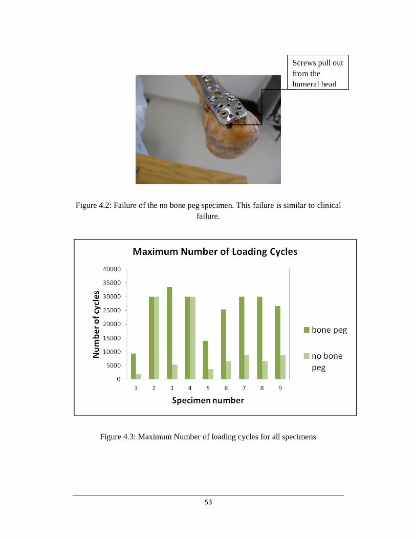
53
Figure 4.2: Failure of the no bone peg specimen. This failure is similar to clinical
failure.
Figure 4.3: Maximum Number of loading cycles for all specimens
Screws pull out
from the
humeral head

54
4.1.4 Confidence Level of the Mean Number of Cycles to Failure
for Failed NBP
Seven of the nine NBP specimens exhibited poor performance under the cyclic
loading condition. Table 4.2 shows at what confidence level the mean number of
cycles to failure of failed NBP would lie within a specific number of cycles.
Table. 4.2 Confidence level of the mean number of cycles to failure for failed NBP
Mean
Cycles Cycles t-score Confidence level p-value
5929 8000 2.155 96.27% 0.037
5929 9000 3.195 99.06% 0.009
5929 10000 4.235 99.73% 0.003
4.1.5 Damage per Cycle for both type of Fixation System
The performance of the two repair techniques under the cyclic loading was
compared by analyzing the damage per cycle for each specimen depicted by the
slope (mm/cycle) of the position-versus-number-of-cycles graphs. Figure 4.4
shows the comparison of the slopes of a pair of bone peg and no bone peg
specimens. First few hundred cycles were required for the settlement of the
specimens after fixing it with the MTS machine. For that reason, the slope was
very steep for the first few hundred cycles and those cycles were ignored to
calculate the actual slope of the graph. Similar graphs for other specimens are
presented in the appendix. Table 4.3 lists the number of cycles required for 1 mm
damage for each specimen. Paired t-test was performed with six pairs of failed
NBP and BP specimens for comparing the mean cycles required for 1 mm

55
damage of both implant systems. The lower and upper limits for 95% confidence
interval are found to be 737.061 and 4454.761 respectively. As both values are
positive, it suggests that the mean cycles required for 1 mm damage for BP
specimen is greater than that of the failed NBP and their mean difference lies
somewhere between these two positive values. It must be noted that data of
specimen 3 was excluded from this analysis due to its outlying data.
Figure 4.4: Number of cycles and valley load displacement (relative
displacement). The slope of the graph represents the damage per cycle

56
Table 4.3 Number of cycles required for one mm damage for each specimen.
4.2 Discussion of Experimental Result
This study investigated the fatigue behaviour of locking plate fixation with fibular
autograft as medial column for proximal humeral fracture. Gardner et al (2007)
and Lee and Shin (2009) have emphasized the importance of medial column
support. The results of our experimental study have shown that reconstructing the
medial column by using an intramedullary fibular autograft strut creates a more
durable, less deformable construct when tested under clinically relevant cyclic
loads. Proximal humeral fractures treated with locking plate fixation alone healed
with a certain varus deformity after one year (Bjorkenheim et al, 2004). Around
21 of 147 patients found mechanical complications which were closely related to
varus malreductuion (Agudelo et al, 2005). Frankhauser et al (2005) reported that
3 of 27 patients had early varus displacement, 7 screws came out from the
humeral head. In the majority of the reported cases the patients were more than 65
Specimen
number
NBP required cycles
for 1 mm damage
BP required cycles
for 1 mm damage
BP/NBP (required cycles
for 1 mm damage)
1 1712.33 1172.33 0.68
2 4016.06 34086.65 8.48
3 2202.64 26109.66 12.5
4 30835.65 22944.20 0.74
5 159.82 4128.82 25
6 1250 3333.33 2.66
7 1250 5000.00 4.0
8 2777.77 5000.00 1.8
9 909.09 5000.00 5.55

57
years old. Since the proximal humerus is in direct contact with the glenohumeral
joint, which is the most mobile joint of the human body, it is difficult to provide a
stable construct to the proximal humeral fractures. A stable construct is a crucial
requirement during the healing period. Osteoporotic patients have a weak
mechanical structure and reduced bone density, which often results in locking
plate fixation failure (Hepp and Josten, 2007). Thus a proper fixation method for
patients with osteoporotic bone is required for proper healing of the proximal
humeral fractures.
A proper fixation system must possess enough stability during the first few weeks
of the operation under limited shoulder movements (Sahu, 2010). Our chosen
applied repeated cyclic loading of 0 to 110N in this study represents the passive
movement of the humerus during normal daily activities (Edward et al, 2006 and
Siffri et al, 2006). Under such cycling loading it was found that the locking plate
fixation with intramedullary fibular autograft can withstand more than 25
thousand cycles whereas in case of without augmented specimens, seven of nine
specimens failed within few thousand cycles. Two without augmented specimens
(2 and 4) did not fail. Specimen 4 was large and from a male donor. It was
visually assessed that specimens 2 and 4 had slightly better bone quality than the
other specimens. The study result showed that 7 of 9 specimens are failed within
10000 cycles. Normally in the first four to six weeks, patients are allowed passive
ranges of motion. After getting radiographic evidence of fracture healing they are
allowed to start active range of motions (Sahu, 2010). The reported 10000

58
thousand cycles gives roughly 250 cycles per day of shoulder muscles movement
which represents an insufficient amount for the postoperative first few week of
passive movement of the humerus. However, the combination of fibular graft with
locking plate shows a much better performance under fatigue loads. Our study
supports those suggesting that the stability and integrity of the medial column is a
key factor for predicting loss of fixation (Gardner et al, 2007). The bone peg
augmentation technique is useful for displaced fractures without medial column
support for fractures in osteoporotic bone lacking enough integrity.
In this study, a 10 mm wedge shaped osteotomy was created at the level of
surgical neck to simulate the clinical situation for displaced proximal humeral
fracture where there is no inherent medial column support. A two-part proximal
humeral fracture was created to understand the mechanical behaviour of the two
construct system for the type of fracture where medial support is lacking. These
results are not easily applicable for three- or four-part fracture patterns. As the
cyclic load was applied to the humerus, the medial column acts as a structural
shaft and helps transmit load to the humeral head; thus, increases the stability and
decreases the relative movements of the displaced fragments. In the first few
weeks after fracture, inter-fragmentary movements have a great influence on bone
healing. The results of this study show that out of nine, for seven specimens the
damage per cycle for non-augmented locking plate fixation is greater than the
damage per cycle for augmented specimens. Intramedullary fibular autograft with
locking plate fixation is able to provide more stability to the fracture than the

59
locking plate alone. It can also reduce the bone healing period as stability of
fixation system plays an important role in bone healing period (Wehner et al,
2010).
Different types of techniques are developed to improve fixation systems for
repairing fractures of osteoporotic bone. A study showed that the fixation system
with calcium phosphate injection can reduce inter-fragmentary movement and
increase the stiffness of the construct (Known et al, 2002). Using the fibular grafts
as medial column has many advantages. The fibula diameter is suitable for using
as medial column of the proximal humerus. Its size is appropriate for filling the
proximal metaphysis and strong enough for giving compressive strength to the
fracture without medial column support (Gardner et al, 2008). In this study, the
fibular strut was taken from the same location from the ipsilateral fibula. A
thicker fibula can provide more biomechanical support but it should
approximately fill the same amount of the proximal humerus in each specimen. It
is not possible to use same size fibula for every case, in this way we can avoid
large size fibula for small humerus and small size fibula for large humerus.
Previous biomechanical studies have shown that the locking plate fixation with
the bone peg can withstand higher load to failure than the construct without the
bone peg in cases where medial support is lacking (Mathison et al, 2010).
However, the study could not replicate the observed clinical mode of failure

60
(Mathison et al, 2010). In this study, screw pulled out from the humeral head was
observed in non-augmented specimens. In addition, in one specimen (without
bone peg), screw penetration in the articular surface was observed. Varus collapse
(loosening of construct) was also observed for other NBP specimens. One
limitation of our study is the use of cadaveric specimens for fatigue loading.
Naturally in in-vivo situations, the site of the operation is a location of influx of
nutrients to expedite the healing process, which was not replicated in the
experiment.
4.3 Conclusion
This chapter presented the results and the discussion of the experiments. It was
found that the augmented locking plate fixation has a longer fatigue life. It was
also observed that the augmented locking plate fixation is more stable than the
non-augmented construct, which is important for the healing period after
operative treatment. It is important to also note the clinical type of failure (screws
coming out from the humeral head) was observed in our experiment. The
superiority of the augmented constructs over the non-augmented one was
statistically significant. In the next chapter development of finite element model
to simulate the experiment for the static loading condition is described.

61
Chapter 5 Development of Finite
Element Model
This chapter describes the development of a finite element model, which was
compared with the experimental results for the static loading condition. In this
study, the finite element method was used to investigate the principal stress
distribution of bone, possible locations of initial crack development and the
relative displacement of the humeral head and shaft for the static loading
conditions. ABAQUS software was used for simulating the experiment conducted
by Mathison et al, (2010) for both augmented and non-augmented constructs
under the static loading conditions.
5.1 Creating Appropriate Geometry
The first step for developing the model was to provide appropriate geometry for
the bone and the implant system. To simulate the experimental study, the humerus
and the locking plate constructs were modelled in finite element analysis.
Creating the proper geometry of the humerus bone and the locking plate in finite
element models is difficult due to the irregular shapes. In addition, the bone
shapes are obtained from digitized stacks of images obtained from radiographs.

62
For the locking plate, solid works 3D software was used and the dimensions were
taken from the Synthes Technique Guide.
5.1.1 Developing 3D Model of the Humeral Head
Our study used digitized images of the humeral head. The images were obtained
from magnetic resonance imaging (MRI) that can provide a large number of
sequential images. Figure 5.1(a) shows an image representing one of the slices
obtained from the MRI of humeral head. Materialise Interactive Medical Image
Control System (MIMICS) software was used for the visualization and
segmentation of the MRI images and for creating 3-D rendering of the humerus.
MIMICS was used to convert the MRI slices into a 3-D triangulated surface by
separating the bone from the other tissues like ligament, cartilage etc. in each slice
and then creating a full 3-D model of the digitized bone. Figure 1(b) shows the 3D
model that was created by MIMICS. However, the surface of the model produced
was not smooth enough but rather contained many spikes. For proper finite
element analysis modelling, the surface is required to be smoothed and also
converted into an analytical surface. For the smoothing and converting of the
triangulated surface into analytical surface, the 3-D model was imported into
Geomagic studio 12.

63
Figure 5.1: Image of Humeral Head in different stages: a) Image from MRI, b) Generated
3D model in Mimics, c) Edited appropriate surface in Geomagic Studio 12
In Geomagic Studio 12, the “mesh doctor” was used to remove the spike and
prepare the surfaces for implementing into a 3D model in the ABAQUS software
for finite element analysis. Figure 1(c) shows a final view of the model after
manipulation using Geomagic Studio 12.
5.1.2 Humeral Shaft, Locking Plate Fixation and Fibular
Autograft 3D model Development
3D modelling software Solid Works was used for further modification of the
humeral head and to create the shaft part of the humerus (which was not captured
in MRI), the locking plate and the fibular autograft. According to the experiment
a b
c

64
(Mathison et al, 2010 and Chow et al, 2011) 10 mm osteotomy was created at the
surgical neck of the humerus in Solidworks. The geometry of the shaft was
created in solidworks and the shape was followed by the area 10 mm offset from
the fracture surface. The contour was extruded to create the shaft. Figure 5.2(a)
shows the contour area that was used to create the humeral shaft.
Figure 5.2: (a) Extruded humeral shaft from selected contour, 10 mm offset of
fracture surface (b) Cortical and Trabecular bone assembly
To create the geometry of the locking plate, the manufacturer’s design
specifications were used for the dimensions. To make the model simple, the
numbers of screws were limited to three and their positions were simplified along
the centerline of the plate and perpendicular to it. The fibular autograft was
created in the pre-processor of ABAQUS as a solid part. As 10 mm diameter and
80 mm length fibular autografts were used in the experiment, these dimensions
were used for creating the autografts in ABAQUS.
Selected contour Cortical bone
Trabecular
bone
a b

65
5.2 Developing the ABAQUS Model to Simulate the
Experiment
In order to develop the model in the ABAQUS software for the finite element
analysis, individual parts were imported into an assembly where their respective
interactions can be defined. Then, the parts can be meshed and assigned proper
material properties, boundary conditions and loading.
5.2.1 Importing Parts and Assembly in ABAQUS
As mentioned above, the solid models of the humeral head, shaft and locking
plate fixation were imported as solid parts into ABAQUS and assembled
according to the experimental study (Mathison et al, 2010 and Roxanne et al,
2011). The locking plate was positioned with respect to the bone in its specified
location by using translation and rotation tools. To make cortical and trabecular
bone layers in the humeral head, a distinct surface was created to separate the two
types of bone. Tingart et al, (2002) studied that the cortical layer for osteoporotic
bone was around 5 mm. In order to create a 5 mm cortical layer, the humeral head
was scaled down in Solidworks by a trial and error method. The scaled down part
of humeral head was the inner trabecular bone layer. Scaled downed humeral
head was used to cut the full size head and thus it created different layers of the
bone. The humeral shaft was also scaled down and the scaled downed version
shaft was used to “cut” the full sized one and thus, creating a hollow humeral
shaft. Cut instance tool was used to create the screw holes in the bone using

66
screws. The outer core of both the humeral head and the shaft were modelled as
cortical bone. Figure 5.2(b) shows the different layers of bone.
Figure 5.3: (a) Locking plate alone (b) Locking plate with fibular autograft
In the humeral head, the cortical bone layer was merged with the trabecular bone
layer to create a continuous mesh. It was then possible to assign different
properties to trabecular and cortical bone parts in the humeral head. The shaft was
composed of a 5 mm cortical layer. Figure 5.3(a) shows the humerus with the
locking plate fixation alone and 5.3(b) shows the humerus repaired by the locking
plate and the fibular autograft.
5.2.2 Assigning Bone Material Properties and Meshing
The bone material properties used in this study were linear elastic and isotropic
homogeneous. The construct was tested under bending in the experiment and only
the initial linear elastic region of load deflection behaviour was of interest. For the
composite structure of bone, two types of material properties were provided. The
modulus of elasticity of cortical bone and trabecular bone were 14000 N/mm2 and
5000 N/mm2 respectively (Reitbergen, 2004). Poisson’s ratio for both types of
a a b

67
bone was defined as 0.3 (Verhulp et al, 2006). The locking plate and screws were
given the material properties of stainless steel. The modulus of elasticity of
stainless steel was defined 193000 N/mm2 and poisson’s ratio was 0.3. Figure
5.4(a) shows the cross section of humeral head.
(a)
(b)
Figure 5.4: (a) Cross section of bone; (b) Denser mesh applied around the screw
holes
Mesh assignment of the humeral head was a difficult job due to its irregular
shape. The virtual topology which is a tool of ABAQUS to create and correct a
mesh was used to overcome the difficulties associated with the irregular
Cortical bone
Trabecular
bone

68
geometry. Tetrahedral elements were used for all parts because of their ability to
mesh irregular shape. Approximate global seed size of 1.5 mm was used for
meshing all the parts. A denser mesh was assigned to the screw-hole surfaces to
obtain accurate stress development for the bone. Global seed size of 0.5 mm was
used for meshing those regions. Figure 5.4(b) shows the denser mesh used around
the screw holes.
5.2.3 Support System, Surface Interactions and Loading
In the experimental study, the humeral head was fixed in the test pot to simulate
the support system of the glenohumeral joint. The humerus was positioned
horizontally and the load was applied vertically (Mathison et al, 2010). To
replicate this loading and support system in the finite element analysis, all degrees
of freedom were fixed for the anterior and posteriors cortical regions of humeral
head while the loading was applied at the specific position of the humerus
vertically. Figure 5.5 shows the support system and the applied static load on the
model.

69
Figure 5.5: Support and loading condition
The screws were assumed to be fully fixed with the plate and the “tie” constraint
was provided between the screw and the bone. Thus the relative movement
between the bone and the screws were assumed to be zero. For that reason by
using tie constraint, it is not possible to see screw pull out from the humeral head.
Main concern of this study was to investigate the overall maximum principal
stress development in the humeral head and the onset of crack development.
Screw pulls out from the humeral head or failure was not expected here. Using
frictional type of interaction, there will be relative movement between the bone
and the screw but it will make the analysis more complex and time consuming. To
make the analysis simple, tie constraint has been used in this model. The same
type of contact was assigned between the fibular autograft and the humeral head.
Frictional type of interaction with a friction coefficient of 0.2 was assigned
between the locking plate and the bone.
Fixed support
Static
load

70
The applied static load was gradually increased in the experimental study
(Mathison et al, 2010). An 800 N static concentrated load, matching the
experimental failure load was applied in increments of 200N to the finite element
model. During physiological loading conditions, the relative deformation of the
humerus bone is very small. Also according to the experiment, our point of
interest is the initial stiffness which was obtained from the initial linear portion of
the load and displacement curve.
5.3 Results of the Finite Element Analysis and
Comparison with the Experiment
5.3.1 Expected Stress Development
As the bone and implant system construct behave like a cantilever beam, our
expected stress distribution was compression in the lower portion of the bone and
tension in the upper portion of the bone. In this study, the load was applied
perpendicular to axis Z. Figure 5.6(a) and (b) show the distribution of the normal
stress component in both finite element models where compression is found
in the bottom part and tension in the upper part of the bone.

71
Figure 5.6: (a) Distribution of for the non-augmented implant system; (b) for
the augmented implant system
Tension
Compression
Tension
Compression
(a)
(b)

72
5.3.2 Downward Deformation and Relative Displacement of the
Head and Shaft
The downward deformation of the augmented implant system is less than the
downward deformation exhibited by the augmented implant system. Figure 5.7
shows the load vs. downward displacement graph for both implant systems.
Identical nodes from the end of the humerus were selected to obtain the
deformation. The deformation of the non augmented implant system for 800 N
load was 15.32 mm whereas the deformation for the augmented implant system
was 3.12 mm.
Figure 5.7: Load vs. downward displacement of the humerus end points obtained
from the finite element models of both types of constructs
In the case of NBP, the slope of the load vs. deformation curve was observed to
increase after 100 N load. This change of slope is due to the fact that the upper
surface of the bone shaft came in contact with the lower surface of the locking
A

73
plate fixation after applying approximately 100 N load (point A). Consequently,
the combined stiffness of the bone and the plate assembly increased which
resulted in less deformation per N load. Figure 5.8 shows the deformation shape
of the NBP specimen for 100 N load corresponding to point A in the load
displacement curve.
Figure 5.8: The deformation of NBP specimen for 100 N load (point A)
In the experimental study, the initial stiffness of the two constructs was
determined by comparing the interface behaviour between the humeral head and
shaft. This was done by comparing the relative displacement of the humeral head
and shaft. For calculating the relative displacement during the experiment, two
points were extracted from the either side of the gap or fracture. In the finite
element model, the relative displacement at different load was calculated similar
to the experiment. Node displacements along the 3 axes were considered to
represent the relative movement along the axis of the construct. Figure 5.9(a) and

74
(b) show the position of points that were used for calculating relative movement
for both the experiment and the finite element analysis model.
(a)
(b)
Figure 5.9: (a) Relative displacement points for experiment (Mathison et al,
2010); (b) FE model
The initial stiffness of the constructs was calculated by determining the slope of
initial linear portion of load and relative displacement curve in the experimental
study. In our finite element model the same procedure was followed. Figure 5.10
(a) and (b) shows the load and relative displacement curve for both the
experiment and the FE model.

75
Figure 5.10: (a) Load vs. relative displacement curve for experiment (Mathison et
al, 2010); (b) Load vs. relative displacement curve for FE model
In the case of NBP, a sudden change of slope (similar to figure 5.8) in the load vs.
relative displacement curve is observed at approximately 100 N load. This was
not observed in the experiments because in our model there was only one screw
for the shaft part. In the actual case, the number of screws is higher than that, and
the lower surface of the plate is always in contact with the upper surface of the
bone and hence their combined stiffness is increased. In the FE model, after
approximately 100 N load, the bone came in contact with the plate and their
(a)
(b
)
b

76
combined stiffness was increased which resulted in less deformation per N load.
To calculate the ratio of the initial stiffness, we used the higher slope since it
represents the actual case when the shaft and the plate are tied together.
The results of the FEA shows that the BP construct is 6.22 times stiffer than the
NBP construct. This is comparable to the experimental study results where the
initial stiffness of the BP construct was recorded to be 3.84 (SD 1.92) times that
of the NPB construct (Figure 5.12). Figure 5.11 shows the initial stiffness of the
specimens for both the experiment and the FE model. The initial stiffness of BP
for the model is 1.66 times higher than the experimental specimen having the
maximum initial stiffness. In case of NBP, the initial stiffness of the model is at
least 1.20 times higher than those of experimental specimens.
Figure 5.11: Initial stiffness (slope of load vs relative displacement) of specimens
(experiment) and FE model

77
Figure 5.12 compared the ratio of initial stiffness of BP and NBP for the finite
element model and the experimental one.
Figure 5.12: Initial stiffness of BP/NBP
5.3.3 Maximum and Minimum Principal Stresses
In the experiment, screw pull out from the humeral head has been observed. By
observing the maximum principal stresses in the finite element analysis, the
maximum stress concentration was observed around the screw-hole areas of the
humeral head for both cases. It should be noted that our finite element analysis
results are limited to the linear elastic range. It is not possible to simulate the
failure of bone in this condition. However, by comparing the onset of failure
between the experiment and the FEA, the maximum principal stresses at the onset

78
of failure which cause crack initiation in bone can be determined. Figure 5.13 (a)
and (b) show the distribution of maximum and minimum principal stresses. The
maximum concentration of both principal stresses was found close to the humeral
head.
The direction of maximum principal stress for both cases was tension and
minimum stress was compression. The ultimate tensile strength of cortical bone is
reported to be 100 to 150 MPa and the ultimate compressive strength is 170 to
Figure 5.13: (a) Maximum principal stress distribution (b) Minimum
principal stress distribution
(a)
(b)
Maximum stress
concentration
Maximum stress
concentration

79
200 MPa (Kummer et al, 1999). For this study the average value of the ultimate
tensile strength 130 MPa and the ultimate compressive strength 190 MPa have
been taken to predict the crack initiation of bone. Figure 5.14 (a) and (b) show the
direction of maximum and minimum principal stress.
Figure 5.14: (a) Direction of maximum principal stress (b) Direction of minimum
principal stress
Figure 5.15 shows the load vs. maximum value of maximum principal stress
curve for both implant systems. The corresponding load of the intersection point
of ultimate tensile strength and the curve is the required load for initiating crack
for tension in both cases. For the augmented implant system, 145 N load is
required for the initial crack, whereas 80 N load is required for the non-
augmented implement system.
Comparing the two implant system for their required load to starting crack in
tension, it was found that the bone peg construct increased the load 1.81 times the
no bone peg construct.
(a) (b)

80
Figure 5.15: Load vs. maximum principal stress
Figure 5.16 shows the load vs. maximum value of minimum principal stress curve
for both implant systems. The corresponding load of the intersection point of
ultimate compressive strength and the curve is the load for initiating crack in both
cases for compression. For the augmented implant system, 473 N load is required
for the initial crack, whereas 252 N load is required for the non-augmented
implement system.
Comparing the two implant system for their required load to starting crack in
compression, it was found that the bone peg construct increased the load 1.88
times the no bone peg construct.
Ultimate
tensile strength

81
Figure 5.16: Load vs. minimum principal stress
5.4 Discussion of the Results
Based on the available literature, this is the first attempt of finite element analysis
to examine the mechanical behaviour of the augmented locking plate fixation for
the proximal humeral fracture with and without mechanical augmentation. The
model shows that the augmented specimen can increase the initial stiffness 6.22
times than the non-augmented one. This ratio is higher than the experimental
findings, mainly because of the higher stiffness of the BP in the model. The
reason may be that in the finite element model, an average value of bone material
property has been used, whereas, in actual case, the bone property may vary
within a larger range. The diameter and material properties of the fibular graft is
also different for different specimens. For that reason, the initial stiffness of the
Ultimate compressive
strength

82
BP from the model is higher than the experimental one whereas for NBP, the
difference is relatively smaller.
In the experiment, the initial stiffness graph showed non-linearity after certain
load and the stiffness was calculated by determining the initial linear part of the
curve. To make the analysis simple, only linear elastic analysis was investigated
using finite element analysis. It is observed that the linear elastic finite element
analysis can simulate the experimental results, however further model
development is required to bolster this finding. Moreover, it is not possible to
assume the nature of crack propagation or failure load for the implants using this
simplified model. Only crack initiating load was calculated for both cases and the
ratio of required load may represent the failure load ratio of the two types of
implant system.
In the case of creating the bone geometry, the humeral head required the highest
attention. Most failures in the experiment occurred in the humeral head. The
cortical thickness of humeral head and the trabecular bone density varies within a
wide range. In the FE model, an average value was used for the cortical thickness
of the humeral head. Bone material was assumed to be linear elastic and isotropic.
This was done to keep the model as simple as possible. In reality, bone is
anisotropic and its properties vary within a considerably large range. To make the
geometry of locking plate simpler the screws were along the centre line of the

83
plate and the number of screws was three. My main concern was to understand
the relative displacement of the implant system and the required load to start
cracking. The number of screws may have a lesser effect on this behaviour. The
tie constraints was used between screws and bone surface, which make the screws
fixed to the bone surface. Future models investigating the fatigue behaviour of the
implant system will have to improve the properties of the interaction between the
bone and the screws to simulate the pulling out of the screws.
Comparing the experimental results and the finite element analysis, it is possible
to conclude that the behaviour of the implant system with and without
augmentation under the static loading condition can be predicted using finite
element analysis. Both the finite element analysis and the experiment concluded
that the augmented implant system can increase both the initial stiffness and
required load for initiating crack.

84
Chapter 6 Conclusion and Discussion
Treatment of displaced proximal humeral fracture is difficult especially for
patients with osteoporotic bone and fractures with lack of medial support.
Locking plate fixation is a technique recommended for treatment of proximal
humeral fractures with poor quality bone. Importance of a medial column to
improve the locking plate fixation was supported by different studies (Gardner et
al, 2008; Lee and Shin, 2008; Osterhoff et al, 2011). The purpose of this study
was to understand the mechanical behaviour of augmented locking plate fixation
under the conditions of clinically relevant cyclic loading. The hypothesis of this
study was that the locking plate fixation system augmented by fibular struts will
be stiffer, more stable and will sustain higher clinically relevant cyclic loading
than the without augmented fixation system.
In addition to this experimental study, a finite element analysis was also
performed to simulate the experiment for the static loading conditions and the
result of numerical analysis was compared with the experimental one. The finite
element analysis supported our experimental finding and showed the potential
location of crack initiation in the augmented constructs.

85
6.1 Brief Description of the Experiment
Nine pairs of cadaveric specimens were utilized to understand the fatigue
behaviour of the augmented locking plate. In this study, a wedge shaped
osteotomy and 10 mm defect in the surgical neck were created to simulate the
clinical situation for displaced proximal humeral fracture where there is no medial
column support. This helps in understanding the mechanical behaviour of the two
construct system for the type of fracture where medial support is lacking. 80 mm
segment of fibular diaphysis was used as bone peg. In each pair of humerus, one
was fixated with a 3 holes proximal humeral locking plate alone and the other one
was fixated with the locking plate fixation and fibular autograft. 110N cyclic load
was applied to the humerus in a specific position to replicate the passive
movement of the glenohumeral joint.
In our study, we continued our testing more than 25000 cycles or up to failure of
the construct whichever comes earlier. This number has been chosen based on the
assumption that the fracture would be biologically healed (negligible risk of
further dislocation of the fracture) within a six week period after the operative
treatment. This six weeks includes a rehabilitation program in which a patient
perform approximately 150 repetitions of exercises three times per day which
starts immediate after operation and further passive and active movements with
regular mobility. Lill et al (2003) used 1000 cycles, Edwards et al (2006) used
5000 cycles and Siffri et al (2006) used 10000 cycles in their biomechanical

86
experiments. These twenty five thousand cycles is well above the number of
cycles that were used in these studies.
6.2 Experimental Results and Discussion
The results of this study have shown that the augmented construct are more stable,
durable and deformation is comparatively lower than the non-augmented one
when tested under clinically relevant cyclic loads. The hypothesis of this study
was confirmed by showing that the locking plate fixation with the intramedullary
fibular graft can withstand more than 25 thousand cycles whereas in the case of
non-augmented specimens, out of nine specimens seven failed within few
thousand cycles and average cycles to failure for these seven non augmented
constructs with standard deviation was 59292543. Statistical analysis has shown
that the mean cycles of the augmented constructs is at least 3 times or more cycles
than that of the failed non-augmented constructs (T-stat 3.93 > Tcritical 1.943, at
95% CL, p-value 0.004). From paired t-test, it was found that the mean number of
cycles for 1mm damage for the bone peg specimen was higher than that for the
failed no bone peg specimen. In this study, through the cyclic loading condition,
the clinical mode of failure where screws pull out or come out from the humeral
head was observed in the specimens without the bone peg.

87
The present biomechanical study result showed that locking plate fixation with
intramedullary fibular graft can increase stability of the repair system during the
passive movement period of the humerus allowing for the bone healing procedure.
It also has a longer fatigue life than the locking plate alone. Intramedullary fibular
graft may play an important role for improving repair technique of osteoporotic
bone fractures. Use of a fibular graft has some biological advantage as it can
improve bone stock. It can prevent the screws pull out from the humeral head.
Thus the fibular graft can help to prevent varus collapse. In our study, varus
collapse has occurred only for non-augmented specimens. Our result can be
supported by the initial clinical results of the study reported by Garden et al
(2008). Our previous study also showed that the fibular graft can increase failure
load and initial stiffness under the static loading condition (Mathison et al, 2010).
Another recent study compared similar construct with locking plate fixation alone
for synthetic bone under the cyclic loading condition and found that augmented
construct was stiffer and less relative movement of bone fragment in humeral
head (Osterhoff et al, 2011). Brianza et al (2010) combines the Expert Proximal
Humeral Nail with a specially developed locking plate and found that the addition
of a locking plate created a stiffer construct with less inter-fragmentary motion
when tested in axial compression and also in a combined axial and torsional
cyclic loading condition. Brianza et al’s study results can be compared with our
study result where we augmented the locking plate fixation with an
intramedullary fibular graft.

88
In our study, two non-augmented specimens did not fail. Those may have had
better bone quality. Due to small number of male data, we were unable to explain
the influence of gender in our study result. Also we did not explore hand
dominance in our results.
6.3 Finite Element Analysis Findings
The other objective of this study is to develop 3-D finite element model of both
types of constructs and the model results have been compared with previous
experimental study (Mathison et al, 2010) of our research group. To create the
complex geometry of humerus, magnetic resonance imaging was used and for
locking plate fixation dimensions were taken from the manual. To replicate the
experiment, a 10 mm osteonomy was created in the surgical neck. Both types of
constructs were fixated to the humerus and trabecular and cortical bone properties
were used as input for the material properties in the finite element models. The
humerus was positioned horizontally, all degrees of freedoms were fixed on the
surface of the humeral head to simulate the experiment and a vertical 800 N static
load (matching the experimental failure load) was applied at the end of the
humerus where the load increment was 200 N.
Downward Deformation of non augmented construct for 800 N load was 15.32
mm whereas for augmented construct, it was 3.12 mm. The ratio of initial
stiffness of the constructs with fibula struts was 6.22 times the locking plate
fixation alone. From our previous experiment we obtained the ratio 3.84 (SD

89
1.92) which is lower that the finite element model result (Mathison et al, 2010).
Some screws came out from the humeral head when they were tested for both the
static and the cyclic loading conditions. From the finite element analysis, we
observed maximum concentration of maximum and minimum principal stress
close to the screw holes of the humeral head. It is not possible to calculate failure
load and nature of crack propagation from this simple and elastic model. We can
only calculate the load required for initial crack development for tension and
compression using maximum and minimum principal stress. Comparing the two
implant systems for required load to develop initial crack, it was found that fibular
graft can increase the load 1.81 times for tension and 1.88 times for compression.
From this ratio, we can assume that augmented fixation can increase the required
load for starting crack in the bone. It is important to note that our finite element
analysis results identified the area close to the screw holes to be the weakest point
of the construct.
Comparing the experimental and simulation results, we can conclude that the
finite element model can mimic the behaviour of the implant systems for the static
loading condition.
6.4 Study Limitations
There are some limitations to our study. To simulate the pull of the supraspinatus,
varus cyclic load was applied to the humeri under isolated condition. This is a
simplification of the complex nature of the fracture fragments and the in-vivo

90
plate fixation behaviour. To understand accurate mechanical behaviour of the
fixation more experiments are required under different loading conditions. In our
study, we observed intra-articular screw penetration for only one specimen
whereas it is a more common clinically observed complication.
Cadaveric specimens were used under the cyclic loading conditions to understand
the fatigue behaviour of the implant systems. It was not possible to replicate the
bone remodelling process during the healing period in this study. For this
particular reason the performance in the first few thousand cycles under a
relatively small cyclic loading was the focus of our study.
To simplify the model, a wedge shaped two-part fracture has been chosen to
simulate medial metaphyseal comminution in this experiment. Most of the
displaced fractures that required operative treatments are three or four part types
of fracture. Similar two-part fracture models are normally used for differemt
proximal humeral fracture fixation studies (Lill et al, 2001; Edwards et al, 2006;
Siffri et al, 2006; sterhoff et al, 2011). This result will not be easily applicable to
three or four part types of fracture.
In the finite element method, to make the model simple, only a minimum number
of locking screws were created and their positions were simplified along the
centerline of the plate and perpendicular to it. In reality, more screws are used and
their orientation is rather erratic. Bone material was assumed to be linear elastic

91
and isotropic to keep the model as simple as possible. In reality, bone is
anisotropic and its properties vary within a considerably large range. Although it
can be assumed that this anisotropy does not affect the behaviour of the implants
within a small range of applied static load. This simple and elastic linear model
cannot describe the crack propagation and failure load of the constructs.
6.5 Recommendation for Future Works
To understand the mechanical behaviour of the augmented construct,
more experiments are required in the future for different loading conditions. A
"two part" fracture model cannot always simulate the actual comminuted
fractures. Many displaced fractures constitute three or four displaced part types.
In the future, three or four part fracture models may be used to investigate the
possible repair options.
For the finite element model, we utilized a simple geometry; only three screws
were used for the locking plate fixation. Future work can include a more accurate
representation of the fixation geometry. In addition, plastic nonlinear material
models can be incorporated to understand the fatigue behaviour and failure of the
construct. The behaviour of bone can be modelled more accurately by considering
its transversally isotropic material. In our model, we also used an average value of
cortical bone thickness and modulus of elasticity for the cancellous bone. Future
work should include using variable thickness of cortical bone and variable

92
material properties of bone to understand the exact behaviour of the fixation and
its interaction with the bone.

93
References
1. Agudelo J., Schurmann M., Stahel P., Helwig P., Morgan S., Zechel W.
Analysis of efficiency and failure in proximal humerus fractures treated
with locking plates. Journal of Orthopaedic Trauma 2007; 21(10):676-681.
2. Anglen J., Kyle R.F., Marsh J.L. Locking plates for extremity fractures. Jo
urnal of American Academy of Orthopaedic Surgeons 2009; 17:465‐472.
3. Augat P., Burger J., Schorlemmer S., Henke T., Peraus M., Claes L. Shear
movement at the fracture site delays healing in a diaphyseal fracture
model. Journal of Orthopaedic Research 2003; 21(6):1011-1017.
4. Atkinson, P.J. Quantitative analysis in cortical bone. Nature 1964; 201:
373-375.
5. Baron, J.A., Karagas, M., Barrett, J., Kniffin, W., Malenka, D., Mayor,
M., Keller, R.B. Basic epidemiology of fractures of the upper and lower
limb among Americans over 65 years of age. Epidemiology 1996; 7(6):
612-618.
6. Barrios C, Brostrom LA, Stark A, Walheim G. Healing complications
after internal fixation of trochanteric hip fractures: the prognostic value of
osteoporosis. Journal of Orthopaedic Trauma 1993; 7: 438–442.

94
7. Becker E.H., Kim H., Shorofsky M., Hsieh A.H., Watson J.D., O’Toole
R.V. Biomechanical comparison of cadaveric and commercially available
synthetic osteoporotic bone models [abstract]. AAOS 2011 Annual
Meeting Proceedings 2011; 700: 831.
8. Bjorkenheim J.M., Pajarinen J., Savolainen V. Internal fixation of
proximal humeral fractures with a locking compression plate: a
retrospective evaluation of 72 patients followed for a minimum of 1 year.
Acta Orthopaedica Scandinavica 2004; 75: 741-745.
9. Bloom R.A., Bloom M.B. A comparative estimation of the combined
cortical thickness of various bone sites. Skeletal Radiology 1980; 5:167-
70.
10. Bloom R.A., Laws J.W. Humeral cortical thickness as an index of
osteoporosis in women. British Journal of Radiology 1970; 43:522-7.
11. Brianza S., Plecko M., Gueorguiev B., Windolf M., Schwieger K.
Biomechanical evaluation of a new fixation technique for internal fixation of
three-part proximal humerus fractures in a novel cadaveric model. Clinical
Biomechanics 2010; 25:886-92.
12. Boyd S.K. and Nigg, B.M. Biological material. Biomechanics of the
Musculo-skeletal System, 3rd
edition, 2006; John Willey and Sons.
13. ShoppingTrolley.Net. Bone Type, 2011.
http://www.shoppingtrolley.net/lesson1-bone-types.shtml. (Accessed:
August 2011).

95
14. Buckwalter J.A., Einhorn T.A., Bolander M.E., Cruess R.L. Healing of the
musculoskeletal tissues. In: Heckman JD (ed) Fractures in adults.
Lippincott–Raven, Philadelphia, New York 1996; 261–304.
15. Chow R., Begum F., Beaupre L. Carey J.P., Adeeb S., Bouliane M.
Proximal Humeral Fracture Fixation:Locking Plate Construct +/-
Intramedullary Fibular Allograft. Journal of Shoulder and Elbow Surgery
2011 (accepted).
16. Charles M., Court-Brown B.C. Epidemiology of adult fractures: A
Review. Injury 2006; 37: 691-7.
17. Clavert P.h., Zerah M., Krier J., Mille P., Kempf J.F., Kahn J.L. Finite
element analysis of the strain distribution in the humeral head tubercles
during abduction: comparison of young and osteoporotic bone. Surgical
and Radiologic Anatomy 2006; 28:581-587.
18. Claes L., Palme U., Palme E., Kirschbaum U. Biomechanical and
mathematical investigations concerning stress protection of bone beneath
internal fixation plates. Biomechanics. Principales and Applications 1982;
325-330.
19. Cook S.D., Skinner H.B., Weinstein A.M., Haddad R.J. Stress distribution
in the proximal femur after surface replacement effects of prosthesis and
surgical techniques. Biomater Med Devices Artif Organs 1982; 10: 85-
102.
20. Edwards S.L., Wilson N.A., Zhang L.Q., Flores S., Merk B.R. Two-part
surgical neck fractures of the proximal part of the humerus. A

96
biomechanical evaluation of two fixation techniques. Journal of Bone and
Joint Surgery (Am.) 2006; 88:2258-64. doi:10.2106/JBJS.E.00757
21. Egol K.A., Ong C.C., Walsh M., Jazrawi L.M., Tejwani N.C., Zuckerman
J.D. Early Complications in Proximal Humerus Fractures (OTA Types 11)
Treated With Locked Plates. Journal of Orthopaedic Trauma. 2008; 22:
159-164.
22. Foruria A.M., Carrascal M.T., Revilla C., Munuera L., Sotelo J.S.
Proximal humerus fracture rotational stability after fixation using a
locking plate or a fixed-angle locked nail: The role of implant stiffness.
Clinical Biomechanics 2010; 25: 307-311.
23. Franklen V.H. and Nordin M. Biomechanics of bone, Basic Biomechanics
of the Musculoskeletal System, 3rd
edition 2001; Lippincott Williams and
Wilkins.
24. Fankhauser F., Boldin C., Schippinger G. A new locking plate for unstable
fractures of the proximal humerus. Clinical Orthopaedics and Related
Research 2005; 176–81.
25. Gardner M.J., Weil Y., Barkner J.U., Kelly B.T., Helfet D.L., Lorich D.G.
The Importance of Medial Support in Locked Plating of Proximal
Humerus Fractures. Journal of Orthopaedic Trauma 2007; 21: 185-191.
26. Gerber C., Werner C.M., Vienne P. Internal fixation of complex fractures
of the proximal humerus. Journal of Bone and Joint Surgery (Br.) 2004;
86:848-855.

97
27. Haidukewych G.J. Perspectives on modern orthopaedics: innovations in
locking plate technology. Journal of American Academy of
Orthopaedic Surgeons 2004; 12: 205–212.
28. Haddad F.S., Duncan C.P. Cortical onlay allograft struts in the treatment
of periprosthetic femoral fractures. Instr Course Lect 2003;52:291-300.
29. Hall M.C., Rosser M. The structure of the upper end of the humerus with
reference to osteoporotic changes in senescence leading to fracture. Can
Med Assoc J 1963; 88:290-294.
30. Hawkins R.J., Bell R.H., Gurr K. The three-part fracture of the proximal
part of the humerus. Operative treatment. Journal of Bone and Joint
Surgery (Am.) 1986; 68: 1410-14.
31. Hessmann M.H., Hansen W.S., Krummenauer F., Pol T.F.¸ Rommens M.
Locked plate fixation and intramedullary nailing for proximal
humerus fractures: a biomechanical evaluation. Journal of Trauma 2005;
58:1194–1201.
32. Hepp P., Josten C. Biology and Biomechanics in osteosynthesis of
proximal humerus fractures. European Journal of Trauma and Emergency
Surgery 2007; 33 (4): 337–344.
33. Huiskes R., Chao EY-S. A survey of finite element methods in
orthopaedic biomechanics: the first decade. Journal of Biomechanics
1983; 16: 385-409.

98
34. Iannotti J.P., Ramsey M.L., Williams G.R., Warner J.P. Non-prosthetic
management of proximal humeral fractures. Journal of Bone and Joint
Surgery 2003; 85: 1575-93.
35. Jowsey J. Age changes in human bone. Clinical Orthopaedics and Related
Research 1960; 17: 210-217.
36. Kanis J.A., Johnell O., Oden A. Long-term risk of osteoporotic fracture in
Malmo. Osteoporosis International 2000; 11(8): 669-674.
37. Keon Oh. J., Sahu D., Ahn Y.H., Lee S.J., Tsutnami S., Hwang J.H., Jung
D.Y., Perren S.M., Oh C.W. Effect of fracture gap on stability of
compression plate fixation: A finite element study. Wiley InterScience,
2009; DOI 10.1002/jor. 20990.
38. Kitson J., Booth G., Day R. A biomechanical comparison of locking plate
and locking nail implants used for fractures of the proximal humerus.
Journal of Shoulder and Elbow Surgery. 2007; 16(3): 362-366.
39. Kwon B.K., Goertzen D.K., O’Brien P.J. Biomechanical evaluation of
proximal humeral fracture fixation supplemented with calcium phosphate
cement. Journal of Bone and Joint Surgery (Am.) 2002; 84(6):951–961.
40. Koval K.J., Blair B., Takei R. Surgical neck fractures of the proximal
humerus: A laboratory evaluation of ten fixation techniques. The Journal
of Trauma 1996; 40: 778-783.

99
41. Kummer J.K., Spivak J.M., DiCesare P.E., Feldman D.S., Koval K.J.,
Rokito A.S., Zuckerman J.D. Implant biomaterials. Orthopaedics: A Study
Guide 1999; 45-48.
42. Lacroix D., Murphy L.A. and Prendergast P.J. Three dimensional finite
element analysis of glenoid replacement prostheses: A comparison of
keeled and pegged anchorage systems. Transactions of the ASME. 2000;
122.
43. Lee C.W. and Shin S.J. Prognosic factors for unstable proximal humeral
fractures treated with locking-plate fixation. Journal of Shoulder and
Elbow Surgery 2009; 18(1): 83-88.
44. Lever J., Aksenov S., Zdero R., Ahn H., Mckee M., Schemitsch E.
Biomechanical analysis of of plate osteosynthesis systems for proximal
humerus fractures. Journal of Orthopaedic Trauma 2008; 22(1), 23-29.
45. Levine, R. S. Injury to the extremities. In A. M. Nahum & J. W. Melvin
(Eds.), Accidental injury 2002; 491–522: New York: Springer-Verlag.
46. Lill H., Hepp P., Korner J., Kassi J.-P., Verheyden A.P., Josten C., Duda
G.H. Proximal humeral fractures: how stiff should an implant be? A
comperative mechanical study with new implants in human specimens.
Archives of Orthopaedic and Trauma Surgery 2003; 123: 74-81.

100
47. Lienau J., Schell H., Duda G.N., Seebeck P., Muchow S., Bail H.J. Initial
vascularisation and tissue differentiation are influenced by fixation
stability. Journal of Orthopaedic Research 2005; 23(3):639-645.
48. Lungershausen W., Bach O., Lorenz C.O. Locking plate osteosynthesis for
fractures of the proximal humerus. Zentralbl Chir 2003;128:28 –33.
49. Mathison C., Chaudhary R., Beaupre L., Reynolds M., Adeeb S., Bouliane
M. Biomechanical analysis of proximal humeral fixation using locking
plate fixation with an intramedullary fibular allograft. Clinical
Biomechanics 2010; 25(7): 642-46.
50. Meema H.E., Meema S. Measurable roentgenologic changes in some
peripheral bones in senile osteoporosis. Journal of American Geriatrics
Society 1963; 11:1170-82.
51. Meier R.A., Messmer P., Ragazzoni P., Rothfischer W., Gross.
Unexpected high complication rate following internal fixation of unstable
proximal humerus fractures with an angled blade plate, Journal of
Orthopaedic Trauma 2006; 20(4): 253-260.
52. Mackenzie B. Range of Movement.
http://www.brianmac.co.uk/musrom.htm, 2004. (Accessed: August 2011).
53. McElhaney J., Fogle J., Byers, E., Weaver, G. Effect of embalming on the
mechanical properties of beef bone. Journal of Applied Physiology 1964;
19:1234-6.

101
54. McBroom R.J., Cheal E.J., Hayes W.C. Strength reductions from
metastatic defects in long bones. Journal of Orthopaedic Research 1988; 6:
369-78.
55. Montgomery D.C. Design and analysis of experiments, 7th
edition 2009;
Willey.
56. Neer, C.S. Displaced proximal humeral fractures: Part 1. Classification
and evaluation. Journal of Bone and Joint Surgery (Am.) 1970; 52:1077-
1089.
57. Nutrition Division. Department of National Health and Welfare, Ottawa.
Average Height and Weight of Canadians by Age and Sex. 1953 Survey.
58. Osterhoff G., Baumgartner D., Favre P., Wanner G.A., Gerber H.,
Simmen H.P. Medial support by fibula bone graft in angular stable plate
fixation of proximal humeral fractures: an in vitro study with synthetic
bone. Journal of Shoulder and Elbow Surgery 2011(Accepted).
59. Reitbergen, B.V. Finite element modelling. The Physical Measurement of
Bone 2004; IOP Publishing Ltd.
60. Orthopaedic List.com, 2008. http://www.orthopaediclist.com/implant-
identification-detail.asp?XrayID=220 (Accessed: August 2011).
61. Orr T.E. and Carter D.R. Stress analysis of joint Arthoplasty in the
proximal humerus. Journal of Orthopaedic Research 1985; 3: 360-71.

102
62. Owsley K.C., Gorczyca J.T. Displacement/screw cut out after open
reduction and locked plate fixation of humeral fractures. Journal of Bone
and Joint Surgery (Am.) 2008; 90(2):233-40.
63. Palvanen M., Kannus P., Parkkari J. Update in the epidemiology of
proximal humeral fractures. Clinical Orthopaedics and Related Research
2006; 442: 87-92.
64. Poppen N.K. And Walker P.S. Normal and abnormal motion of the
shoulder. Journal of Bone and joint Surgery (Am.) 1976; 58(2):195-201.
65. Pathria, M. N. Radiologic analysis of trauma. In A. M. Nahum & J. W.
Melvin (Eds.). Accidental Injury 2002; 103–120: New York: Springer-
Verlag.
66. Resch H., Povacz P., Fro¨hlich R., Wambacher M. Percutaneous fixation
of three- and four-part fractures of the proximal humerus. The Journal of
Bone and Joint Surgery (Br.) 1997; 79: 295–300.
67. Ring D. Current concepts in plate and screw fixation of Osteoporotic
proximal Humerus fractures. Injury 2007; 38S3: S59-S68.
68. Rose P.S., Adams C.R., Torchia M.E., Jacofsky D.J., Haidukewych G.G.,
Steinmann S.P, Rochester M.N. Locking plate fixation for proximal
humeral fractures: Initial results with a new implant. Journal of Shoulder
and Elbow Surgery 2007; 16: 202-207.
69. Rybicki E.F., Simonen F.A., Mills E.J., Hassler C.R., Scoles P., Milne D.
and Weis E.B. Mathematical and experimental studies on the mechanics of
plated transverse fractures. Journal of Biomechanics 1974; 7: 377-384.

103
70. Salas C., Mercer D., DeCoster T.A. and Taha M.M.R. Experimental and
probabilistic analysis of distal femoral periprosthetic fracture: a
comparison of locking plate and intramedullary nail fixation. Part B:
probabilistic investigation. Computer Methods in Biomechanics and
Biomedical Engineering 2011; 14(2); 175-182.
71. Sahu R. Philos locking plates in proximal humerus fractures-literature
review. The Internet Journal of Health 2010; 11(1).
72. Schell H., Epari D.R., Kassi J.P., Bragulla H., Bail H.J., Duda G.N. The
course of bone healing is influenced by the initial shear fixation stability.
Journal of Orthopaedics Research 2005; 23(5):1022-1028.
73. Siffri P.C., Peindl R.D., Coley E.R., Norton J., Connor P.M., Kellam J.F.
Biomechanical analysis of blade plate versus locking plate fixation for a
proximal humerus fracture: comparison using cadaveric and synthetic
humeri. Journal of Orthopaedic Trauma 2006; 20: 547-54.
74. Skinner H.B., Kim A.S., Keyak J.H., Mote C.D. Femoral prosthesis
implantation induces changes in bone stress that depend on the extent of
porous coating. Journal of Orthopaedics Research 994; 12: 553-63.
75. Strohm P.C., Kostler W., Sudkamp N.P. Locking plate fixation of
proximal humerus fractures. Techniques in Shoulder & Elbow Surgery
2005;6:8-13.
76. Sudkamp N., Bayer J., Hepp P., Oestern H., Kaab M., Luo C., Plecko M.,
Wendt K., Kostler W., Konrad G. Open reduction and internal fixation of

104
proximal humeral fractures with use of the locking proximal humerus
plate. Result of a prospective, multicenter, observational study. Journal of
Bone and Joint Surgery 2009; 91-A: 1320-1328.
77. Synthes Canada Ltd. 3.5 mm LCP proximal humerus plate stainless steel
and titanium technique guide 2002.
http://www.synthes.com/MediaBin/International%20DATA/036.000.863.
pdf. (Accessed: July 2011).
78. The Orthopedic Institute of New Jersey, Leading MD, Inc., 2009.
http://www.leadingmd.com/shoulder_njsmsc/overview.asp. (Accessed:
July 2011).
79. Tingart M.J., Apreleva M., Stechow D.V, Zurakowski D., Warner J. J.,
The cortical thickness of the proximal humeral diaphysis predicts bone
density of the proximal humerus. Journal of Bone Joint Surgery (Br) 2002;
85-B:611-7.
80. Valle C.J.D., Rokito A.S., Birdzell G., Zuckerman J.D. Biomechanics of
shoulder. Basic Biomechanics of the Musculoskeletal System, 3rd
edition
2001, Lippincott Williams and Wilkins.
81. Verhulp E., Rietbergen B.V., Miller R., Huiskes R. Indirect determination
of trabecular bone effective tissue failure properties using micro-finite
element simulations. Journal of Biomechanics 2008; 41: 1479-1485.

105
82. Wehner T., Claes L., Niemeyer F., Nilte D., Simon U. Influence of the
fixation stability on the healing time – A numerical study of a patient-
specific fracture healing process. Clinical Biomechanics 2010; 25: 606-
612.
83. Weinstein D.M., Bratton D.R., Ciccone W.J., Elias J.J. Locking plates
improve torsional resistance in the stabilization of three-part proximal
humeral fractures. Journal of Shoulder and Elbow Surgery 2006; 15(2):
239-243.
84. Wijgman A.J., Roolker W., Patt T.W. Open reduction and internal fixation
of three and four part fractures of the proximal part of the humerus.
Journal of Bone and Joint Surgery (Am.) 2002; 84-A: 1919-1925.
85. Williams G.R. Jr, Copley L.A., Iannotti J.P. The influence of
intramedullary fixation on figure of eight wiring for surgical neck
fractures of the proximal humerus: a biomechanical comparison. Journal
of Shoulder and Elbow Surgery 1997; 6: 423-428.
86. Winter D. Biomechanics and Motor Control of Human Movement, 3rd
Edition 2005; John Wiley & Sons.
87. Woo S.L.-Y., Simon B.R., Akeson W.H., McCarty M.P. An inter-
disciplinary approach to evaluate the effect of internal fixation plate on
long bone remodelling. Journal of Biomechanics 1977; 10: 87-95.
88. Zdero R., Elfallah K., Olsen M., Schemitsch E.H. Cortical screw purchase
in synthetic and human femurs. Journal of Biomechanical Engineering
2009; 131:094503.

106
Appendix

107
Figure: Appendix 1 Damage per cycle for specimen 6
Figure: Appendix 2 Damage per cycle for specimen 7

108
Figure: Appendix 3 Damage per cycle for specimen 8
Figure: Appendix 4 Damage per cycle for specimen 9

109
Figure: Appendix 5 Number of cycles versus displacement for BP specimen 6
Figure: Appendix 6 Number of cycles versus displacement for NBP specimen 6
400 cycles
400 cycles

110
Figure: Appendix 7 Number of cycles versus displacement for BP specimen 7
Figure: Appendix 8 Number of cycles versus displacement for NBP specimen 7
500 cycles
400 cycles

111
Figure: Appendix 9 Number of cycles versus displacement for BP specimen 8
Figure: Appendix 10 Number of cycles versus displacement for NBP specimen 8
500 cycles
500 cycles

112
Figure: Appendix 11 Number of cycles versus displacement for BP specimen 9
Figure: Appendix 12 Number of cycles versus displacement for NBP specimen 9
500 cycles
550 cycles

113
Figure: Appendix 13 Sample of data sheet