universiti teknikal malaysia melaka study the...
TRANSCRIPT

2
UNIVERSITI TEKNIKAL MALAYSIA MELAKA
STUDY THE EFFECT OF HIGH TEMPERATURE CYCLE
EXPOSURE TO EVALUATION ON EMBRITTLEMENT OF
WELDED PRESSURE VESSEL STEEL
This report submitted in accordance with requirement of the Universiti Teknikal
Malaysia Melaka (UTeM) for the Bachelor Degree of Manufacturing Engineering
(Material Engineering) with Honours.
By
NURULHUDA BT ARIFIN
Faculty of Manufacturing Engineering
April 2009
5
ABSTRACT
The research of the effect of high temperature cycle exposure to evaluation on
embrittlement of welded pressure vessel steel has been developed purposely in order to
study the effect of embrittlement behavior of pressure vessel steel after expose to
elevated temperature. The temper embrittlement has been usually observed in pressure
vessel steel that serving at high temperature, due to the segregation of trace elements at
the grain boundaries and/or carbide interface. This impurity elements segregation will
cause deterioration hardness of the steel based on the theory. These pressure vessel steel
have a potential for temper embrittlement. Therefore, the research and observation in the
mechanical properties of tempered welded area are very important in order to support
on-going steel development for services temperature and also useful to avoid the
embrittlement during the services. The pressure vessel steel (ASTM A516) have been
chosen to be used as the type of specimens in this research. The welded area of pressure
vessel steel is on service temperature of pressure vessel (450°C) at different exposure
time. The welded area for all specimens after exposure was characterized by
microstructure observation, EDS, and hardness measurement. Based on these results,
evaluation on embrittlement is discussed in order to determine the approximate effect of
high cycle temperature to embrittlment behavior. Experimental results revealed that
temper embrittlement hardly affect the hardness value for welded area and the
microstructure characteristics of pressure vessel steel are significantly changed.
6
ABSTRAK
Kajian tentang kesan pendedahan suhu tinggi kepada penaksiran sifat kerapuhan bagi
kimpalan pengandang yang diperbuat daripada besi telah di jalankan bagi tujuan untuk
mengkaji kesan terhadap sifat kerapuhan pengandang selepas terdedah kepada
penigkatan suhu. Pada kebiasaannya, sifat kerapuhan ini selalunya diperhatikan hadir
dalam pengandang besi yang beroperasi dalam suhu yang tinggi,; dimana fonomena ini
berlaku di sebabkan oleh pengasingan unsur-unsur pada butiran sempadan. Berdasarkan
kepada teori, pengasingan unsur-unsur kotoran atau cemaran ini akan mengakibatkan
kemusnahan serta kerapuhan besi. Oleh yang demikian, kajian dan pemerhatian keatas
ciri-ciri mekanikal kawasan kimpalan adalah sangat penting bagi memastikan
pengandang mampu beroperasi pada suhu operasi dan untuk mengelakkan daripada
berlakunya kerapuhan ketika pengandang sedang beroperasi. Jenis besi pengandang
yang telah di gunakan sebagai spesimen dalam kajian ini adalah ASTM A516. Bagi
melengkapkan kajian ini, kaedah yang dijalankan adalah dengan melakukan pendedahan
spesimen kepada peningkatan suhu sekitar 450°C terhadap setiap spesimen yang
mempunyai kawasan kimpalan. Sifat-sifat mekanikal bagi kawasan kimpalan (kesemua
spesimen) selepas melalui proses peningkatan kekerasan dianalisis melalui pemerhatian
mikrostrukturnya, ujian pengesahan unsure-unsur serta ujian takat kekerasan yang
dilakukan pada suhu bilik. Berdasarkan keputusan ujian-ujian yang telah dijalankn, hasil
analysis di bincangkan bagi tujuan mengenal pasti kesan pendedahan suhu yang tinggi
terhadap sifat kerapuhan pengandang. Keputusan kajian jelas menunjukkan bahawa
pendedahan pengandang kepada suhu yang tinggi sangat mempengaruhi keputusan ujian
kekerasan bagi setiap zone kimpalan dan sifat-sifat mikrostruktur besi pengandang
tersebut turut berubah dengan nyata sekali.
7
DEDICATION
This thesis is gratefully dedicated to my parents, Mr. Arifin Abdullah and Sara Ahmad,
my beloved family, my supervisor lecturer Mohamad Haidir B. Maslan, and my
supported friends towards accomplishing this research.

8
ACKNOWLEDGEMENTS
Firstly, I want to gratitude to god, most gracious and merciful to show me guidance in
accomplishing this research. Without that, I could not finish this project. I would also
like to state my appreciation also to those individuals who involved whether directly or
indirectly in assisting and aiding me throughout completing this project. Million of
thanks to my project supervisor Mr. Mohamad Haidir Bin Maslan and my examiner Mr.
Edeerozey Abd. Manaf for their time spending, encouragement, teaching, guidance and
ideas for my research. Their contributions will not been forgotten. In this opportunity
also, I wish to express my appreciation to the technicians involved in helping to
complete this project. The most important is my appreciation to my parents and family.
Lastly to all my friends who give their morale support and sharing this challenging time
and beautiful life together.

9
TABLE OF CONTENTS
Abstract i
Abstrak ii
Dedication iii
Acknowledgement iv
Table of Contents v
Appendices viii
List of Figures ix
List of Tables xi
List of Abbreviations, Symbols, Specialized Nomenclature xii
1. INTRODUCTION 1
1.1 Research Background 1
1.2 Problem Statement 2
1.3 Objectives of Project 3
1.4 Scope of Project 3
1.5 Hypothesis 3
2. LITERATURE REVIEW 4
2.1 Metallurgy 4
2.1.1 Body-Centered Cubic Crystal 4
2.1.2 Faced-Centered Cubic Crystal 5
2.2 The Iron-Carbon Diagram 6
2.3 Phase In Steel 7
2.3.1 Austenite 7
2.3.2 Martensite 7
2.3.3 Ferrite 8
2.3.4 Cementite (Fe 3 C) 8
2.3.5 Pearlite 9
10
2.3.6 Bainite 9
2.4 Welded 9
2.4.1 Submerged Arc Welding (SAW) 9
2.4.2 Post Weld Heat Treatment (PWHT) 11
2.5 Welding Metallurgy 12
2.5.1 Weld Ability 12
2.5.2 Heat Affected Zone 13
2.5.3 Weld Metal 16
2.5.4 Base Metal 17
2.6 Material Factors 18
2.7 Embrittlement 19
2.7.1 Intergranular Embrittlement 19
2.7.2 Temper Embrittlement 20
2.7.2.1 Temper Martensite Embrittlement 22
2.7.2.2 Reversible Temper Brittleness 23
2.7.2.3 Factor of Temper Embrittlement 25
2.8 Carbide and Nitride Precipitation 26
2.9 Intermetallic Phase 26
2.10 Principle Effect Element on Steel 27
2.10.1 Chromium 27
2.10.2 Molybdenum 27
2.11 Previous Research on Temperature Embrittlement in Pressure Vessel 28
2.11.1 Microstructure and Properties of Post Weld Heat Treated 28
2.25Cr-1Mo weld Metal
2.11.2 Critical Assessment of the Degree of Temper Embrittlement 29
in 2.25Cr-1Mo Steel
2.11.3 Cracking of 2.25Cr-1Mo steel Tube/ Stationary Tube-Sheet 31
Weldment of Heat-Exchanger

11
3. RESEARCH METHODOLOGY 33
3.1 Introduction 33
3.2 Research Design 34
3.3 Material 35
3.3.1 ASTM A516 35
3.4 Sample Preparation 36
3.4.1 Welding Process (SMAW) 36
3.4.2 Cutting Process 37
3.4.3 Milling Process 38
3.5 Exposure 39
3.5.1 Tempering 39
3.6 Metallurgy Technique 40
3.6.1 Grinding and Polishing Process 40
3.6.2 Etching Process 41
3.7 Microstructure Observation 42
3.8 Testing 42
3.8.1 Hardness Test 42
3.8.2 Energy Dispersive X-ray Spectroscopy (EDS) Test 44
3.8.3 Tensile Test 44
4. RESULT & DISCUSSION 46
4.1 Introduction 46
4.2 GDS Data Analysis 46
4.3 Material Factor of Pressure Vessel Steel (ASTM A516) 47
4.4 Tensile Properties 48
4.5 Physical Observation after Tempering 49
4.6 Microstructure Analysis 50
4.6.1 Microstructure of Base Metal 51
4.6.2 Microstructure of HAZ Area 52
4.7 EDS Analysis 54
4.8 Hardness Result 61

12
4.8.1 Hardness Comparison 61
4.9 Yield Strength Analysis 65
5. CONCLUSION & RECOMMENDATION 67
5.1 Conclusions 67
5.2 Recommendation 68
REFERENCES 69
13
APPENDICES
A Gantt Charts of PSM 1 and PSM 2
B Grinding Process Procedures
C Polishing Process Procedures
D Etching Process Procedures
E Microstructure Observation Procedures
F Tensile Test Procedures
G Hardness Test Procedures
H EDS Composition Results
I Tensile Test Results
J Material Safety Data Sheet (MSDS)
14
LIST OF FIGURES
2.1 The structure of a body-centered cubic metal 4
2.2 The structure of a faced-centered cubic unit cell 5
2.3 The Iron-Carbon phase diagram 6
2.4 The iron- carbon diagram 8
2.5 Submerged Arc Welding 10
2.6 J impact transition temperature of welded and tempered weld metals 11
2.7 Hardness profile through an autogenously weld 13
2.8 Schematic of a fusion weld in steel, presenting proper terminology for 14
the various region and interfaces.
2.9 Schematic showing the temperature gradient during welding along HAZ 15
2.10 Schematic representation of microstructures local to the HAZ of welds 16
2.11 Grain structure and various zones in a fusion weld. 17
2.12 Characteristic typical weld zone. 18
2.13 Schematic effect of the temperature on impact toughness of alloy steel 20
2.14 Room-temperature Charpy V-notch impact energy versus 23
Tempering temperature
2.15 The schematic phenomenon of temper embrittlement 24
2.16 AES spectra transcrystalline and intercrystalline fracture of 26
2.25Cr-1Mo steel.
3.1 The process flow of research design 34
3.2 Raw Material 36
3.3 View of HAZ Area 37
3.4 Flow of cutting Process 38
3.5 Milling Process 39
15
3.6 Placing Sample into Rear Furnace 39
3.7 Tempering Profile 40
3.8 Polishing Process 41
3.9 Etching Process 41
3.10 Axial Zeiss Optical Microscope 42
3.11 Rockwell Hardness Machine 43
3.12 Indents Part during Hardness Measurement for Welded area; Heat 43
Affected Zone, and Base Metal
3.13 Scanning Electron Microscope (SEM) Machine 44
3.14 Standard Rectangular Tensile Test Specimens 45
Source: American Standard Testing Material (2003)
3.15 Universal Testing Machine (UTM) 45
4.1 Stress versus Strain Result for Raw Material (ASTM A516) 48
4.2 Sample of pressure vessel steel after tempering process; 1 Hours (A); 50
10 Hours (B); and 100 Hours (C).
4.3 Ferrite and Pearlite Microstructure 51
4.4 Micrograph of Base Metal area; before tempering (A); 1 hour tempering 52
(B); 10 hours tempering (C); and 100 hours tempering (D)
4.5 Micrograph of HAZ area; before tempering (A); 1 hour tempering (B); 53
10 hours tempering (C); and 100 hours tempering (D).
4.6 Micrograph of base metal area using EDS analysis; 1 hour tempering (A); 54
10 hours tempering (B); and 100 hours tempering (C).
4.7 Micrograph of HAZ area using EDS analysis; 1 hour tempering (A); 55
10 hours tempering (B); and 100 hours tempering (C).
4.8 Graph of percentage weight of carbon pick-up for base metal area after 56
tempering
4.9 Graph of EDS analysis after tempering for base metal; 1 hour tempering 57
(A); 10 hours tempering (B); and 100 hours tempering (C).
16
4.10 Graph of percentage weight of carbon pick-up for HAZ area after 58
Tempering
4.11 Graph of EDS analysis after tempering for HAZ area; 1 hour tempering 59
(A); 10 hours tempering (B); and 100 hours tempering (C).
4.12 Theory of calculated diffusion distance in ferrite for 1 hour of 60
tempering time
4.13 Graph showing the hardness distribution for base metal, HAZ and 61
welded area; before tempering (A)
4.14 Graph showing the hardness distribution for base metal, HAZ and 62
welded area; 1 hours tempering (B); 10 hour tempering (C), and
100 hour tempering (D).
4.15 Graph showing the decreasing of hardness after tempering in base 64
metal area
4.16 Graph showing the decreasing of hardness after tempering in HAZ area. 64
17
LIST OF TABLES
3.1 Physical Data of ASTM A516 35
3.2 Chemical Content 36
4.1 GDS Result 47
4.2 Tensile Properties Comparison 49
4.3 Weight (%) of each element in base metal after tempering 56
4.4 Weight (%) of each element in HAZ area after tempering 58
4.5 Vickers hardness result for Base metal 63
4.6 Vickers hardness result for HAZ area 64
4.7 Yield Stress (σy) of HAZ and base metal element analysis 66
18
LIST OF ABBREVIATIONS, SYMBOLS, SPECIALIZED
NOMENCLATURE
% - Percentage
ASTM - American Society for Testing and Materials
AISI - The American Iron and Steel Institute
HR - Rockwell hardness number
0C - Degrees Celsius
DBTT - Ductile to Brittle Transition
HAZ - Heat Affected Zone
BM - Base Metal
WM - Weld Metal
Cr - Chromium
Mo - Molybdenum
SEM - Scanning Electron Microscope
BCC - Body-center cubic
FCC - Faced-centered cubic
Fe3C - Carbide
CCT - Continuous Cooling Transformation
EDX - Energy-dispersive X-Ray spectroscopy
TTT - Time Temperature Transformation
SEM - Scanning Electron Microscope
C - Carbon
wt% - Weight percentage
Cl - Chlorine
Al - Aluminium
Si - Silicon
Fe - Ferum
α - Alfa
19
γ - Gamma
Lab - Laboratory
FKP - Faculty of Manufacturing Engineering
max - Maximum
µ - Micron
Mpa - Mega Paschal
in - Inch
mm - Millimeter
cm - Sentimeter
SAW - Submerged Arc welding
PWHT - Post Weld Heat Treatment
UE - Unembrittlement
LE - Light Embrittlement
ME - Medium Embrittlement
HE - Heavy Embrittlement
EDS - Energy Dispersive X-ray Spectroscopy
20
CHAPTER 1
INTRODUCTION
1.1 Research Background
Towards developing the weld consumables for tempered martensite steels, evaluation on
embrittlement is importance in order to prevent catastrophic failure of structure, often
originating from brittle fracture of welded joint for engineering system that are operating
at high temperature cycle (650 °C - 1100°C) that involve contact of metallic with
combustion product gases, such as gas turbines, steam generator, and numerous
petrochemical process vessel. Based on that, this research is developing in order to study
the effect of high temperature cycle exposure to evaluation on embrittlement of welded
pressure vessel steel.
The composition element and structure on base metal are quite different compared to
heat affected zone (HAZ) of welded. This is because of the distribution of molybdenum
within the alloy parent plate and in the weld heat affected zone. Heavy partition of
molybdenum to carbide phases in the metal would result temper embrittlement, as
molybdenum retard the segregation of embrittling tramp element to grain boundaries.
Therefore, the research and observation in the mechanical properties of tempered welded
area are very important in order to support on-going steel development for services
temperature > 620°C and also useful to avoid the embrittlement during the services.
Overall part of this study was a consideration of the effect of time tempering on the
welded zone (base metal and HAZ area) in a submerged-arc welding. For this purpose,
the medium carbon steel (ASTM A516) is used in this research. The 2.25Cr-1Mo steel
21
has much advantage for both ambient and high temperature steel. The potential uses of
this steel are in the electrical power generation plants and petrochemical industries.
These pressure vessel steel have a potential for temper embrittlement that lead to
toughness degradation and a reduction of a critical flaw size for brittle fracture.
A survey of literature shows the composition to be controlling parameter for temper
embrittlement, in-particular the presence of impurity elements such as P and the
presence of elements such as Mo which effect of impurity segregation. Much
information is available to describe embrittlement phenomenon for Cr-Mo steels. This
research also describe the mechanism of temper embrittlement and microstructure
characteristic which allows the structural integrity of potential embrittled vessels for the
purpose of remaining life assessment and plant life extension
To determine the properties of the steel after tempering process, several tests like
Vickers Hardness, EDS analysis and microstructure observation will be done for all
samples that tempering at elevated temperature according to ASTM references.
1.2 Problem Statement
Temperature embrittlement is a phenomenon where ductile metal become brittle due to
high temperature exposure. This exposure temperature will also affect the hardness of
the welded pressure vessel area. Therefore, it is important in order to evaluate
embrittlement of material which all of this data could be use for further research to
define the fracture of welded pressure vessel steel.
22
1.3 Objectives of Project
The purpose of this project is:
i) To study the effect of high temperature cycle exposure to evaluation on
embrittlement of welded pressure vessel steel.
ii) To determine the effect of precipitation elements on microstructure
development and hardness of based metal and heat affected zone (HAZ) of
welded pressure vessel steel.
1.4 Scope of Project
This study will focus on the effect of high temperature cycle exposure to evaluation on
embrittlement of welded pressure vessel steel. This project will include the literature
review on the phase transformation in steel, temper embrittlement, the preparation and
procedure of heat treatment at elevated temperature, mechanical testing by using
hardness measurement and microstructure observation. The microstructure for each
specimen will be observed under the Optical Microscope. While the composition of
element in welded area (base metal and HAZ) after tempering will be observed using
EDS analysis.
1.5 Hypotheses
The tempering process with different exposure time will cause the significant reduction
of the hardness of the steel, due to the segregation of trace elements at the grain
boundaries and/or carbide interface. The microstructure is also different between Heat
affected zones (HAZ), and base metal (BM) when expose at elevated high temperature.
23
CHAPTER 2
LITERATURE REVIEW
2.1 Metallurgy
2.1.1 Body-Centered Cubic Crystals
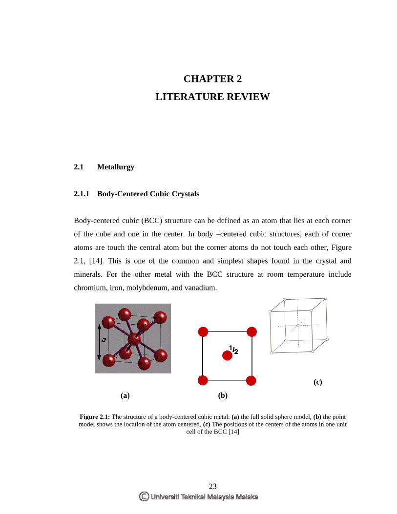
Body-centered cubic (BCC) structure can be defined as an atom that lies at each corner
of the cube and one in the center. In body –centered cubic structures, each of corner
atoms are touch the central atom but the corner atoms do not touch each other, Figure
2.1, [14]. This is one of the common and simplest shapes found in the crystal and
minerals. For the other metal with the BCC structure at room temperature include
chromium, iron, molybdenum, and vanadium.
(c)
(a) (b)
Figure 2.1: The structure of a body-centered cubic metal: (a) the full solid sphere model, (b) the point
model shows the location of the atom centered, (c) The positions of the centers of the atoms in one unit
cell of the BCC [14]
24
Figure 2.1 (c) shows that nine atoms associate with each cell but some atoms are shared
among several cells [11]. Each corner atom in body-centered cubic is shared by eight
cells. Since the coordination number is less for BCC than FCC, so also is the atomic
packing factor for BCC is lower (0.68 versus 0.74) [15].
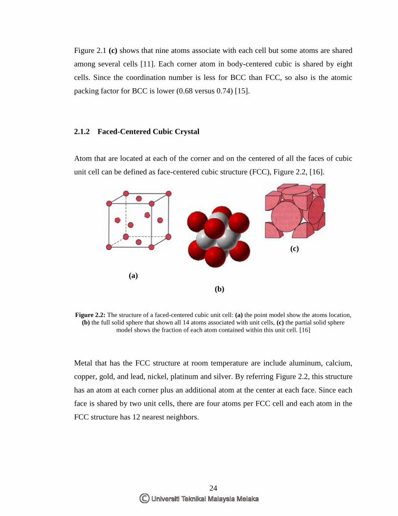
2.1.2 Faced-Centered Cubic Crystal
Atom that are located at each of the corner and on the centered of all the faces of cubic
unit cell can be defined as face-centered cubic structure (FCC), Figure 2.2, [16].
(c)
(a)
(b)
Figure 2.2: The structure of a faced-centered cubic unit cell: (a) the point model show the atoms location,
(b) the full solid sphere that shown all 14 atoms associated with unit cells, (c) the partial solid sphere
model shows the fraction of each atom contained within this unit cell. [16]
Metal that has the FCC structure at room temperature are include aluminum, calcium,
copper, gold, and lead, nickel, platinum and silver. By referring Figure 2.2, this structure
has an atom at each corner plus an additional atom at the center at each face. Since each
face is shared by two unit cells, there are four atoms per FCC cell and each atom in the
FCC structure has 12 nearest neighbors.