universiti putra malaysia structural behaviour of …
TRANSCRIPT
UNIVERSITI PUTRA MALAYSIA
STRUCTURAL BEHAVIOUR OF PRE-CAST CONCRETE SANDWICH PANEL UNDER AXIAL AND LATERAL LOADING
ABDELFATTAH ELNUR ABBAKER
FK 1999 37
STRUCTURAL BEHAVIOUR OF PRE-CAST CONCRETE SANDWICH PANEL UNDER AXIAL AND LATERAL LOADING
By
ABDELFATTAH ELNUR ABBAKER
Thesis Submitted in Partial Fulfilment of the Requirements for the Degree of Master of Science in the Faculty of
Engineering Universiti Putra Malaysia.
April 1999

Dedicated to my beloved Father, Mother,
Brothers and Sisters

ACKNOWLEDGMENTS
PRAISES and THANKS belong ONLY to ALLAH S.W.T for giving me the
opportunity to work with the following wonderful people and friends through-out the
course of this study. They are:
The chairman of the supervisory committee, Dr. Waleed Abdel Malik Thanoon
and the members, Prof. Abang Abdullah Abang Ali, Assoc. Prof. Dr. Abdul Aziz Abdul
Samad and Assoc. Prof. Dr. Mahgoub Osman Mahgoub, whose excellent supervision,
continuous encouragement, guidance, and numerous discussion were instrumental for
the completion of the thesis, and Prof. Dr. D. N. Trikha whose comments and support
are appreciated. The Head of the department, Dr. Mohd. Razali whose support is also
appreciated: I would appreciate the support of En. Abdul Halim, Tn. Hj. Ghazali of the
Concrete Laboratory, my kind relatives, and friends, without whose support and
encouragement it would not had been easy to finish my study; finally all who have
helped directly or indirectly I hope Allah will bless them.
ALHAMUIJLLAH
iii
TABLE OF CONTENTS
Page
ACKNOWLEDGMENTS.................. ...... ... ...... ... ... ... ...... .......... 111 LIST OF TABLES... ... ... ... ... ... ... ... ... ... ... ... ........ ... ... ... ... ... ... ..... VI LIST OF FIGURES ... ... ... ... .. , ... ... ... ... ... ... ... ... ... ... ... ... '" ... ... ... . V111 LIST OF PLATES ......... ... ... .... , . ..................... ... . ,. ... ... ... ... ... ... x LIST OF ABBREVIATIONS ... ... ... ... ... ... ... ... ... ... ... ... ... ... ... ... ... .. Xl ABSTRACT... .. . ... ... ... ... ... ... ... ... ... ... ... ... ... ... ... ... ... ... ... ... ... ... ... Xlll ABSTRAK......... ... ............... ... ......... ... ... ... ...... ...... ... ... ...... ... xv
CHAPTER
I INTRODUCTION General. ..... ......... . , .... ........................ ...... ... ... ... ... ... .. . Industrialised Building Systems ......... ... ... ... ... ... ...... ... ...... . Scope and Objective of the Study ...... ...... ...... ...... ... ... ........ . Layout of the Thesis ... ... ... ... ... ......... ...... ... ... ... ... ... ......... .
1 1 2 3 4
n LITERATURE REVIEW ......... ... ...... .... ,. ... ... ... ... ........ ... 5 Introduction ....... ... . ,. ... ... ... ... ... . .. ... . . . . . . . .. ... ... ... ... . .. . .. ... . 5 Review of Literature ..................... . ,. . . . . . . . . . . . . . . . . . . . . . . . . . . . . . . 6
Concluding Remarks. .. . . . . .. ... ... ... . . . ... ... ... ... ... ... ... .. . . 19 ill METHODOLOGY ... ...... ... ...... ...... ... ......... ... ... ... ........ 21
Introduction ... ....... , . .................. ... ...... ... ... ...... '" . .. ... .. . . 21 Experimental Test ................................. ....... ...... ...... .... 22
Sandwich Panel/Specimen ... ... ... ... .. . ... ... ... . .. . .. ... ... ... 22 Materials ... ... . , . ... ... ............ ....... ......... ... ...... ........... 23 Testing Set-up ...... ...... ... ...... ... ................ ... ...... ........ 27 Loading Condition ............ ............ .................. ......... 32
Finite Element modelling ... ...... ... ... ... ... ... ... ... ... ... ... ... ... ... 32
IV RESULTS AND DISCUSSION ... ...... ... ... ... ................... 38 Introduction ... ....... ,. ... ... ... ... . .. ... ... ... ... ... ... . .. ... ... ... ... ... .. 38 Theoretical Analysis (FEM).... ... ... ... ... ... ... ... ... ... ... ... ... ... ... 38
Vertical Axial Load-Strain Relationship... ... ..... ... ... ... .... 39 Lateral Load Deflection Relationship... ... . . . . . . . . . . . . . 44 Flexural Stress Distribution... . . . . . . . . . . . . . . . . . . . . . . . . . . . 50 Shear Stress Contours... ... ... ... ... ... ... ... ... ... ... ..... 55 Concluding Remarks on the Finite Element Analysis 56
Analysis of the Experimental Results ...... ... ... ... ... ... ... ......... ... 58 Elastic Response of Panels to Axial Vertical Compression .... 58 Elastic Response of Panels to Lateral Load ... .. . .. ... ... .. . .. . .. 61 Post-cracking Structural Behaviour ... ... ... ... .... ... ... ... ..... 63 Cracks Pattern... ... ... .... ... ... ... ... ... ... ... ... ... ... ... ... ... ... 67
IV
Concluding Remarks on the Experimental Analysis ... . . . 69
V CONCLUSION AND RECOMMENDATION FOR FUTURE WORK ... . .. . . . . . . . . . . . . . . . . . . . . . . . . . . . . . . . . . . . . . . . . 76 Conclusion ... . . . . . . . . . . . . . . . . . . . . . . . . . . . . . . . . . . . . . . . . . . . . . . . . . . . . . . . . . . . . 76
Structural Response of the Sandwich Panel Subjected to Vertical load .. . ... . . . ... ... ...... . . . . .. . . . . . .... . .. ... 77 Structural Response of the Sandwich Panel Subjected to Lateral load .. . . .. .. . . . ... ... ...... . . . . . ... . . . . . . . .. . .. . 77 Structural Response of the Sandwich Panel Subjected to Combined load... . .. . . . . . . . . . . . . . . . . . . . . . . . . . . . . . . . . . 78
Recommendation for Future Work.... . . . . . . . . . . . . . . . . . . . . . . . . . . . . . . . . . . 79
REFERENCES... ... ..................... .................. ...... ............. ... ... ... 80
APPENDIX A...... ... ...... ... ... ... ... ... ......... ... ...... ............ ...... ... ... 83 B . . . . . . . . . . . . . . . . . . . . . . . . . . . . . . . . . . . . . . . . . . . . . . . . . . . . . . . . . . . . . . . . . . . . . . . 89 C...... ... ...... ... . . . . . . . . . . . . . . . . . . . . . . . . . . . . . . . . . . . . . . . . . . . . . . . . . . . 1 03
VITA . . . . . . . . . . . . . . . . . . . . . . . . . . . . . . . . . . . . . . . . . . . . . . . . . . . . . . . . . . . . . . . . . . . . . . . . . . . . . . . . . . . . . . 126
v
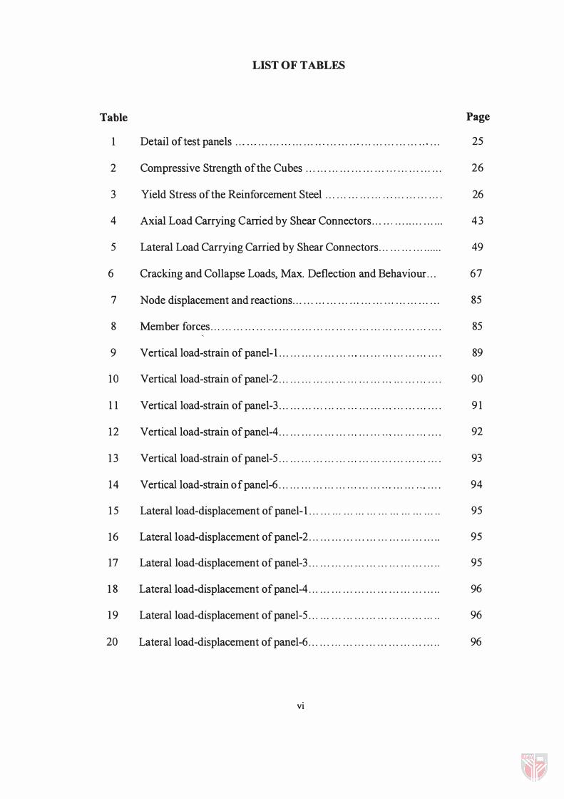
LIST OF TABLES
�� hp
1 Detail of test panels . .. '" . . . . . . '" . . . . . . '" . . . . . . . " . . . . . . . . . . . . . . . '" . . . 25
2 Compressive Strength of the Cubes . . . . . . . . . . . . . . . . . . . . . '" . . . . . . . . . . . . 26
3 Yield Stress of the Reinforcement Steel . . . . . . '" . . . . . , '" . . . . . . . . . . . , . 26
4 Axial Load Carrying Carried by Shear Connectors . . . '" . . . . . . . . . . . . . . 43
5 Lateral Load Carrying Carried by Shear Connectors . . . . . , . . . . . . . . . . . . 49
6 Cracking and Collapse Loads, Max. Deflection and Behaviour. . . 67
7 Node displacement and reactions . . . . . . '" . . . . . . '" . . . . . . '" . . . . . . . . . . . . 85
8 Member forces . . . . . . . . . '" . . . . . . . . . . . . . . . . . . . . . . . . . . . . . . . . . . . . . . . . . . '" . . . . 85
9 Vertical load-strain of panel-I . . . . . . . . . . . . . . . . . . '" . . . . . . '" . . , . . . '" . . . . 89
10 Vertical load-strain of panel-2 . . . . . . . . . . . . . . . . . . '" . . . . . . '" . . , . . . '" . . . . 90
1 1 Vertical load-strain of panel-3 . . . . . . . . . '" . . , . . . '" . . . . . . '" . , . . . . '" . . . . 9 1
12 Vertical load-strain ofpanel-4 . . . . . . . . . . . . . . . . . . '" . . . . , . '" . . . . . . '" . . . . 92
1 3 Vertical load-strain of panel-5 . . . . . . . , . . . . . . . . . . '" . . . . . . . . . . . . . . . '" . . . . 93
14 Vertical load-strain of panel-6 . . . . . . . . . . . . . . . . . . '" . . . . . . '" . . . . . . '" . . . . 94
1 5 Lateral load-displacement of panel-I. . . . . . . . . . . . . . . . . . . . . . . . . . . . . . . . . . . 95
16 Lateral load-displacement ofpanel-2 . .. . . . . . . . . . . . . . . . . . . . . . . . . . . . . . . . . 95
17 Lateral load-displacement of panel-3 . . . . . . . . . . . . . . . . . . . . . . . . . . . . . . . . . . . 95
1 8 Lateral load-displacement ofpanel-4 . . . . . . . . . . . . . . . . . . . . . . . . . . . . . . . . . . . 96
19 Lateral load-displacement of panel-5 . . . . . . . . . . . . . . . . . . . . . . . . . . . . . . . . . . . 96
20 Lateral load-displacement ofpanel-6 . . . . . . . . . . . . . . . . . . . . . . . . . . . . . . . . . . . 96
vi
2 1
22
23
24
25
26
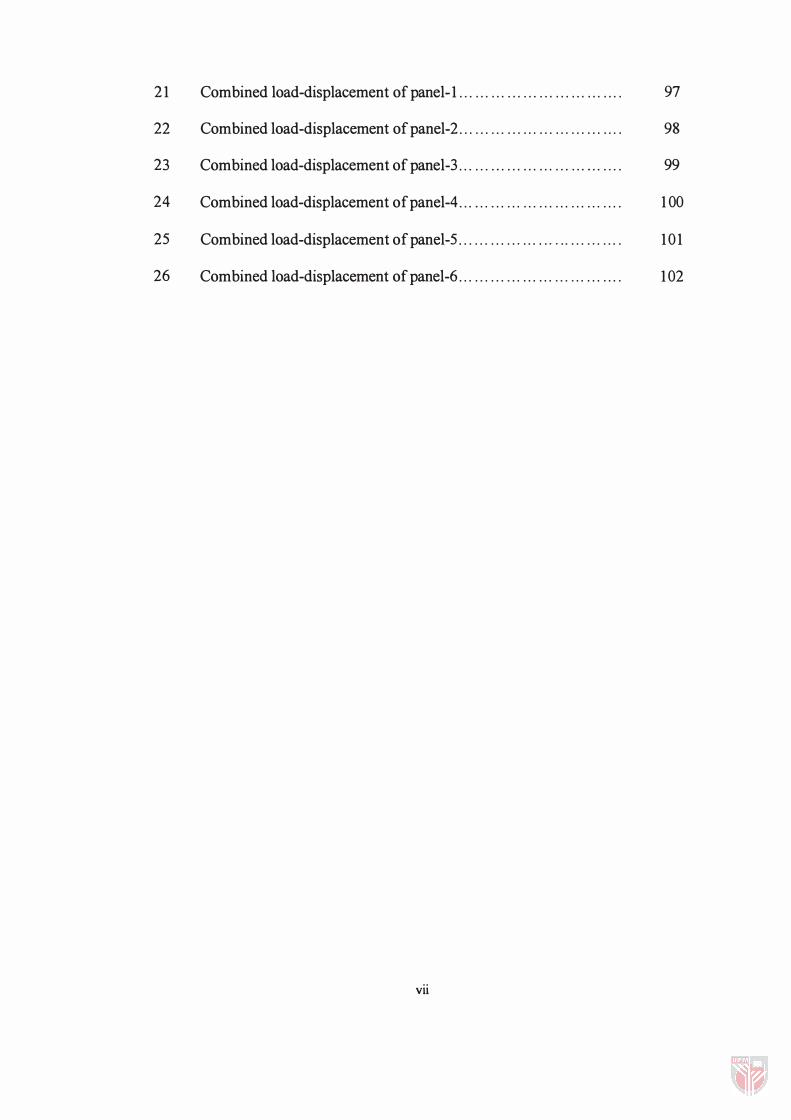
Combined load-displacement of panel- 1 . . . . . . . . . . . . . . . . . . . . . . . . . . . . . . .
Combined load-displacement ofpanel-2 . . . . . . . . . . . . . . . . . . . . . . . . . . . . . . .
Combined load-displacement of panel-3 . . . . . . . . . . . . . . . . . . . . . . . . . . . . . . .
Combined load-displacement of panel-4 . . . . . . . . . . . . . . . . . . . . . . . . . . . . . . .
Combined load-displacement of panel-5 . . . . . . . . . . . . . . . . .. . . . . . . . . . . . . .
Combined load-displacement of panel-6 . . . . . . . . . . . . . . . . . . . . . . . . . . . . . . .
vii
97
98
99
1 00
10 1
1 02
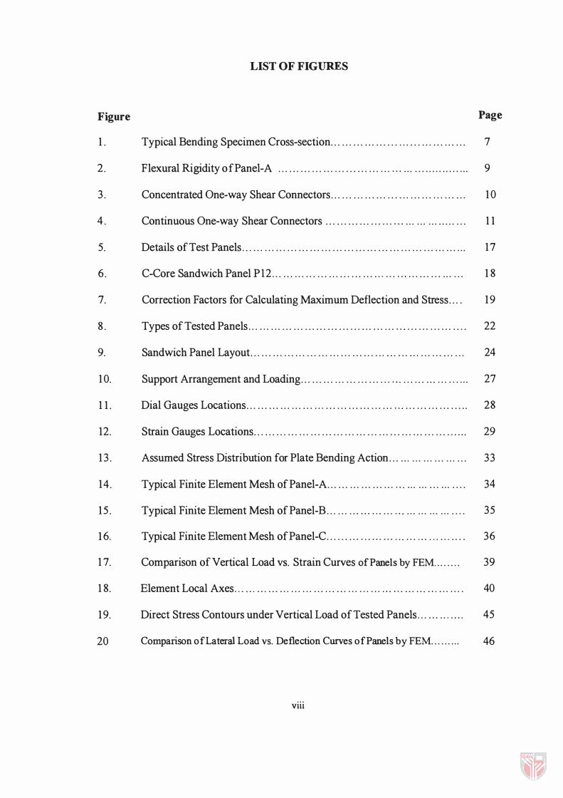
LIST OF FIGURES
Figure Page
1 . Typical Bending Specimen Cross-section. . . . . . . . . . . . . . . . . . . . . . . . . . . . . . . . . . . . 7
2 . Flexural Rigidity of Panel-A . . . . . . . . . . . . . . . . . . . . . . . . . . . . . . '" . . . . . . . . . . . . . . . . . . . 9
3 . Concentrated One-way Shear Connectors . . . . . . . . . . . . . . . . . . . . . . . . . . . . . . . . . . . . 1 0
4 . Continuous One-way Shear Connectors . . . . . . . . . . . . . . . . . . '" . . . . . . . . . . . . . . . . . 1 1
5. Details of Test Panels . . . . . . . . . . . . . . . . . . . . . . . . . . , . . . . . . . . . . . . . . . . . . . . . . . . . . . . . . . . . 17
6 . C-Core Sandwich Panel PI2 . . . . . . . . . . . . . . . . . . . . . . . . . . . . . , . . . '" . . . . . . . . . . . . . . . 1 8
7. Correction Factors for Calculating Maximum Deflection and Stress. . . . 19
8 . Types of Tested Panels . . . . , . . . . . . . . . . . . . . . . . . . . . . . . . . . . . . . . . . '" . . . . . . . . . . . . . . . . 22
9. Sandwich Panel Layout . . . . . . . . . . . . . . . . . . . . . . . . . . . . . . . . . . . , . . . . . . . . . . . . . . . . . . . . . 24
1 0. Support Arrangement and Loading . . . . . . . . . . . . . . . . . . . . . . . . '" . . . . . . . . . . . . . , . . . . 27
1 1 . Dial Gauges Locations . . . . . . . . . . . . . . . . . . . . , . . . . . . . . . . . . . . . . . . '" . . . . . . . . . . . . . . . . . 28
12. Strain Gauges Locations . . . . . . . . . . . . . . . . , . . . . . . . . . . . . . . . . . . . . . . . . . . . . . . . . . . . . . . . . 29
1 3 . Assumed Stress Distribution for Plate Bending Action. . . . . . . . . . . . . . . . . . . . . 33
14 . Typical Finite Element Mesh of Panel-A . . . . . . . . . . . . . . . . . . '" . . . . . . . . . . . . . . . . 34
15 . Typical Finite Element Mesh of Panel-B . . . . . . . . . . . . . . . . . . '" . . . . . . . . . . . . . . . . 35
1 6. Typical Finite Element Mesh of Panel-C . . . . . . . . . . . . . . , . . . ' " . . . . . . . . . . . . . . . . 36
1 7. Comparison of Vertical Load VS. Strain Curves of Panels by FEM.. . . . . . . 39
1 8. Element Local Axes . . . . . . . . . . . . . . . . . . . . . . . . . . . . . . . . . . . . . . . . . . . . . . . . ' " . . . . . . . . . . 40
19. Direct Stress Contours under Vertical Load of Tested Panels . . . . . . . . , . . . . 45
20 Comparison of Lateral Load VS. Deflection Curves of Panels by FEM. . . . . . . . . 46
viii
2 1 .
22.
23.
24.
25.
26.
27.
28.
29.
30.
3 1 .
32.
33.
34.
35.
36.
37
38
39
40
41
42
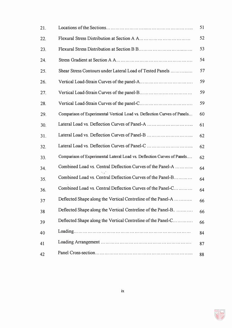
Locations of the Sections . . . . . . . . . . . . . . . . . . . . . . . . . . . . . . . . . . . . . . . . . . . . . . . . . . . . . . . . .
Flexural Stress Distribution at Section A A . . . . . . . . . . . . . . . . . . . . . . . . . . . . . . . . .
Flexural Stress Distribution at Section B B . . . . . . . . . . . . . . . . . . . . . . . . . . . . . . . . . . .
Stress Gradient at Section A A . . . . . . . . . . . . . . . . . . . . . . . . . . . . . . . . . . . . . . . . . . . . . . . . .
Shear Stress Contours under Lateral Load of Tested Panels . . . . . . . . . . . . . . .
Vertical Load-Strain Curves of the panel-A . . . . . . . . . . . . . . . . . . . . . . . . . . . . . . . . . .
Vertical Load-Strain Curves of the panel-B . . . . . . . . . . . . . . . . . . . . . . . . . . . . . . . . . .
Vertical Load-Strain Curves of the panel-C . . . . . . . . . . . . . . . . . . . . . . . . . . . . . . . . . .
Comparison of Experimental Vertical Load vs. Deflection Curves of Panels .. .
Lateral Load vs. Deflection Curves of Panel-A . . . . . . . . . . . . . . . . . . . . . . . . . . . . . .
Lateral Load vs. Deflection Curves ofPanel-B . . . . . . . . . . . . . . . . . . . . . . . . . . . . . .
Lateral Load vs. Deflection Curves ofPanel-C . . . . . . . . . . . . . . . . . . . . . . . . . . . . . .
Comparison of Experimental Lateral Load vs. Deflection Curves of Panels .. . .
Combined Load vs. Central Deflection Curves of the Panel-A . . . . . . . . . . . .
Combined Load vs. Central Deflection Curves of the Panel-B . . . . . . . . . . . .
Combined Load vs. Central Deflection Curves of the Panel-C . . . . . . . . . . . .
Deflected Shape along the Vertical Centreline of the Panel-A . . . . . . . . . . . .
Deflected Shape along the Vertical Centreline of the Panel-B. . . . . . . . . . . . .
Deflected Shape along the Vertical Centreline of the Panel-C . . . . . . . . . . . . .
Loading . . . . . . . . . . . . . . . . . . . . . . . . . . . . . . . . . . . . . . . . . . . . . . . . . . . . . . . . . . . . . . . . . . . . . . . . . . .
Loading Arrangement . . . . . . . . . . . . . . . . . . . . . . . . . . . . . . . . . . . . . . . . . . . . . . . . . . . . . . . . . .
Panel Cross-section . . . . . . . . . . . . . . . . . . . . . . . . . . . . . . . . . . . . . . . . . . . . . . . . . . . . . . . . . . . . . . .
IX
5 1
52
53
54
57
59
59
59
60
6 1
62
62
62
64
64
64
66
66
66
84
87
88
Plate
1
2
3
4
5
6
7
8
9
1 0
LIST OF PLATES
Testing Arrangement . . . . . . . . . . . . . . . . . . . . . . . . . . . . . . . . . . . . . . . . . . . . . . . . . . . . . . . . .
Top Edge Boundary Condition . . . . . . . . . . . . . . . . . . . . . . . . . . . . . . . . . . . . . . . . . . . . .
Bottom Edge Boundary Condition . . . . . . . . . . . . . . . . . . . . . . . . . . . . . . . . . . . . . . . . .
Lateral loading arrangement . . . . . . . . . . . . . . . . . . . . . . . . . . . . . . . . . . . . . . . . . . . . . . . .
Crack Pattern of Panel A-I at Maximum Load . . . . . . . . . . . . . . . . . . . . . . . . . . .
Crack Pattern of Panel A-2 at Maximum Load . . . . . . . . . . . . . . . . . . . . . . . . . . .
Crack Pattern of Panel B-1 at Maximum Load . . . . . . . . . . . . . . . . . . . . . . . . . .
Crack Pattern of Panel B-2 at Maximum Load . . . . . . . . . . . . . . . . . . . . . . . . . .
Crack Pattern of Panel C-l at Maximum Load . . . . . . . . . . . . . . . . . . . . . . . . . .
Crack Pattern of Panel C-2 at maximum Load . . . . . . . . . . . . . . . . . . . . . . . . . . .
x
Page
30
30
3 1
3 1
70
7 1
72
73
74
75
LIST OF ABBREVIATIONS
A Element cross-sectional area
b Breadth of the section
d Effective depth
Ee Modulus of elasticity of concrete
feu Characteristic strength of concrete
fy Characteristic strength of reinforcement
FX X -axis membrane force
FY Y-axis membrane force
FXY Membrane shear force
Gk The characteristic dead load
h Overall depth of the section
I Second moment of area
L Span between end restraints
MX Bending moment about X-axis
MY Bending moment about Y-axis
MXY Torsion moment
Mab Bending moment at support A
Mba Bending moment at support B
FEM Fixed end moment
Ra Reaction at support A
Rb Reaction at support B
xi
SMAX Maximum principal stress
SMIN Minimum principal stress
TMAX Maximum shear stress
QX X -axis shear force
QY Y-axis shear force
� The characteristic imposed load
Sa Angle of rotation at support A
Sb Angle of rotation at support B
y Concrete unit weight
p Percentage of reinforcement
crt Flexural stress at top of the wall
crb Flexural stress at bottom of the wall
xu
Abstract of thesis submitted to the Senate ofUniversiti Putra Malaysia in partial fulfillment of the requirements for the degree of Master of Science.
STRUCTURAL BEllA VIOUR OF PRE-CAST CONCRETE SANDWICH PANEL UNDER AXIAL AND LATERAL LOADING
By
ABDELFATTAHELNUR ABBAKER
April 1999
Chariman: Waleed Abdel Malik Thanoon, Ph.D.
Faculty: Engineering
The sandwich panel is a layered structural system composed of a low density
core material bonded to and acting integrally with, a relatively thin high strength facing
materials held together by shear connectors which gives different degree of composite
action. In a load bearing wall the two facings act as slender columns continuously
supported by shear connectors. Core material usually act as insulation material to
reduce the temperature inside the building. The bending action due to eccentric load or
lateral load is resisted by the tensile and compressive forces developed in outer layers
while shear forces are resisted by the shear connectors. Sandwich panels are used as
exterior walls in multi-unit, residential, commercial and ware house building, providing
structurally and thermal efficient building element.
In this study, the structural behaviour of reinforced concrete sandwich wall
panels has been investigated experimentally in pre and post-cracking phase. Each panel
consists of two outer reinforced concrete layers, interconnected together by different
layout reinforced concrete ribs, which act as shear connectors. Three layouts of shear
xiii
connectors have been selected for the study; these are continuous vertical concrete ribs
and truss type layout ribs inclined at 45° and 67.5° with the vertical.
Finite element method has been used in analysis for comparison with the
experimental test results in the pre-cracking phase and to determine the stress
distribution developed in the different components of the sandwich panel under
different loading conditions. Six specimens of reinforced concrete sandwich panels (two
identical specimens for each shear connector layout) each of size 1200 x 2400 mm
(width x height) have been cast in the laboratory and tested in vertical position under
incremental vertical axial, lateral, and combined axial and lateral loading. The effect of
different shear connector layout on the overall structural behaviour of the panel is
highlighted. Moreover the composite behaviuor of the sandwich panels, the percentage
of load transferred to the ribs and the crack pattern have been investigated and
discussed. The structural response of the sandwich panel in term of deflections have
been found equal to 35 mm, 27 mm and 22 mm for panels type A, B and C respectively.
The lateral collapse load of the tested panels, have been found equal to 97 KN, 40 KN
and 45 KN for panels type A, B and C respectively.
From the results obtained in this study, it has been found that the sandwich panel
with vertical shear connector has a better overall structural response as reflected in the
integrity of the sandwich wall panel systems under the action of combined axial and
lateral loads, in �omparison to sandwich panels with inclined layout shear connectors.
XIV
Abstrak tesis yang dikemukakan Kepada Senat Universiti Puutra Malaysia sebagai memenuhi Keperluan untuk ijazah Master Sains.
TINDAKLAK PANEL APIT KONKRIT PASANG SlAP DI BAWAH BEBANAN PAKSI DAN SISI
Oleh
ABDELFATTAHELNUR ABBAKER
April 1999
Pengerusi: Waleed Abdul Malik Thanoon, Ph.D.
Fakulti: Kejuruteraan
Panel apit adalah satu sistem struktur berlapis yang mengandungi bahan teras
berketumpatan rendah. Bahan teras ini akan bersepadu dan bertindak serasi dengan
bahan permukaan luar yang nipis tetapi berdaya tahan yang tinggi, dan kedua-duanya
akan disatukan oleh penyambung ricih yang akan memberi pelbagai tindakan rencam. Ia
juga akan memberi kekuatan dan kekukuhan yang unggul bagi suatu kuantiti bahan
yang digunakan. -Dalam dinding galas beban ini, dua permukaan luar dalam sistem
tersebut akan bertindak sebagai tiang langsing yang disokong berterusan oleh bahan
teras untuk merintangi daya mampatan dan lengkokan. Untuk lenturan yang disebabkan
oleh beban hidup atau beban angin, bahan permukaan luar akan menanggung
kebanyakan daripada daya tegangan dan mampatan, manakala bahan teras akan
merintangi daya ricihan. Panel apit biasanya digunakan sebagai dinding luaran dalam
bangunan berbilang unit, rumah kediaman, bangunan komersial dan gudang, yang mana
dapat memberikan effisiensi yang tinggi terhadap struktur dan penghabaan dalam
elemen bangunan. Dalam kajian ini, tindaklaku struktur panel apit berkonkrit tetulang
telah diselidik pada keadaan pra dan pascaretakan. Setiap panel terdiri daripada dua
xv
lapisaan konkrit tetulang luaran, disambung bersama oleh konkrit rusuk yang bertindak
sebagai penyambung ricih. Tiga jenis penyambung ricih telah dipilih dalarn kajian ini; ia
terdiri daripada rusuk konkrit tegak berterusan dan rusuk jenis kekuda dengan
kecondongan 45° dan 67.5° dari garis tegak.
Disarnping itu, kaedah unsur terhingga telah digunakan untuk menentukan
ketepatan bagi keputusan eksperimen pada fasa pascaretakan bagi struktur panel apit
berkonkrit tetulang. Pada masa yang sarna, kaedah unsur terhingga juga dipakai untuk
mencari agihan tegasan yang terhasil daipada komponen komponen berlainan dan
penyarnbung ricih. Enam contoh panel apit berkonkrit tetulang (dua contoh yang sama
bagi setiap bentangan penyambung ricih) dengan setiap satu bersaiz 1200 x 2400 mm
(lebar x tinggi) telah siap dituang di dalam makmal dan diuji dalam keadaan tegak di
bawah tokokan beban paksi, sisi dan gabungan kedua-dua beban paksi dan sisi. Kesan
penggunaan bentangan penyambung ricih yang berlainan terhadap tindaklaku struktur
panel apit secara keseluruhannya telah dititikberatkan. Nilai-nilai tindakbalas struktur
panel apit dari segi pesongan, telah ditentukan iaitu 35 mm untuk panel jenis A, 27 mm
untuk panel jenis B dan 22 mm untuk panel jenis C. Nilai-nilai kapasiti muktamad juga
telah ditentukan untuk ketiga-tiga jenis panel iaitu 97 kN, 40 kN dan 45 kN untuk panel
A, B dan C mengikut turutan. Selain itu, sifat panel apit, pratusan rusuk pembawa
kapasiti dan corak corak retakan telah diselidiki dan dibincangkan.
Hasil daripada kajian ini, mendapati struktur panel apit berkonkrit tetulang
dengan penyarnbung ricih tegak memberi pre stasi kestrukturan yang lebih baik,
sepertimana yang ditunjukkan oleh sistem panel apit di bawah tindakan kedua-dua
bebanan paksi dan sisi, dibandingkan dengan penyambung ricih condong.
XVI
CHAPTER I
INTRODUCTION
General
The conventional construction method of multi-storeyed building is to use
framing system consisting of columns to support beams which hold up the roof, floors,
internal partitions and external cladding. The main structural elements are the beams
and the columns. The walls are normally considered as non-load-bearing walls. The
strength of these walls can be exploited because of their high compressive strength. The
use of a pre-cast concrete sandwich panel load-bearing wall can provide an alternative
economical construction method, by eliminating the need for a beam-column frame for
multi-storeyed buildings.
Sandwich panels are composed of two facing shell element boned together
through shear connectors, separated by a layer of insulation. The insulated shell reduces
heating and cooling cost for structure. Pre-cast concrete sandwich panel system can be
constructed to achieve up to 1 OOpercent composite action, depending on the ability of
embedded connectors to transfer the shear generated by longitudinal flexures.
1
2
In general, panels are neither fully composite nor non-composite, but lie some
where in between. When used as a wall, roof or floor element in housing, the sandwich
panel provides exceptional strength, for the amount of the material used. In load bearing
wall the facing shells act as slender columns continuously supported by the shear
connectors, to resist compression and buckling. In bending due to eccentric load or
lateral load, the facing elements resist most of the tensile and compressive forces and
the shear connectors provide resistance to shear forces. The shear connectors and facing
elements act integrally to provide exceptional stiffness to the member.
Industrialised Building Systems
Industrialised building system is a common practice now ill construction
industry and it is possible to obtain factory produced structural elements such as pre-cast
frame, roof and wall. These industries are well developed, and some have facilities,
which are capable of producing almost any precast structural element desired. There are
many commercial types of load bearing pre-cast sandwich panel available in the market.
Few firms have pre-designed elements, catalogued for consumer selection. With a
known building size and loading, the elements for a complete structure are quickly
fabricated from detailed standards and shipped to the site. Other firms fabricate the
elements direct from consumer-supplied designs and details. A recent development of
the concrete products industry has been the specialisation in the production of pre-cast
concrete wall panels. Because manufacturers are looking for new viable product lines,
architects and engineers are pleased with the energy performance and general aesthetics
3
of the panels. In addition contractors have found that the use of sandwich panels allows
their project site to be quickly dried in allowing other trades to work in clean
comfortable environment.
Scope and Objective of the Study
The complexity of the interaction between the various components of the pre
cast concrete sandwich panel systems has led researchers to rely on experimental
observations supplemented with simplified analytical studies. Most experimental work
on the load resistance of the panel has included shear and lor flexural tests. The shear
test performed by applying shearing forces, in the mid-thickness planes of the concrete
wythes to fmd shear capacity of the connectors and the contribution of the insulation to
shear interaction between the concrete wythes. The interface shear is important in
determining the degree of composite action. In a flexural test, a panel is sUbjected to
out-of plane transverse loads to determine the over all flexural capacity of the panel.
The main scope of this research is to investigate the effect of different types of
shear connectors on the structural behaviour of pre-cast concrete sandwich wall panels,
subjected to vertical axial load, lateral load in pre-cracking phase and combined vertical
axial and lateral loading in post cracking phase. Three layouts of shear connectors have
been selected; these are continuos vertical ribs and truss type layout ribs inclined at 45°
and 67.5° with vertical. The study aims to identifY the most efficient type of the shear
connectors, in transferring the load between the outer shells and to study the effect of
4
different shear connector layouts on the overall structural performance of the sandwich
wall panels. In addition, the effect of different layouts shear connector on the crack
patterns, stability, failure mode and ultimate load capacity of the panels are investigated.
Layout of the Thesis
This thesis is divided into 5 chapters, a brief description of the content of these
chapters is presented below:
The first Chapter contains the introduction and the scope of the study. Chapter
IT is devoted to the literature review, which includes topics, related to the structural
behaviour of pre-cast concrete sandwich panel. The methodology used in present study
is covered in Chapter ill that includes the procedure implemented to conduct the
experimental and theoretical investigation. In Chapter IV, results from both theoretical
and experimental results were presented and discussed in details. Chapter V contains
.the conclusion and recommendations for future work.
CHAPTER II
LITERATURE REVIEW
Introduction
Pre-cast concrete sandwich panels are a layered structural system composed of a
low-density core material bonded to, and acting integrally with, relatively thin, high
strength facing materials. The insulated shell reduces heating and cooling cost. In a
load-bearing wall, the two facings act as slender columns continuously supported by the
shear connectors to resist compression and buckling. In bending due to eccentric load
and/or lateral load, the two layers resist most of the tensile and compressive forces,
while the shear connectors provide resistance to shear forces. The sandwich panel offers
high flexural-to-stiffness and high strength-to-weight ratios, compared to other standard
forms of structural sections. The use of sandwich panels offers attractive solutions to
many terrestrial, offshore, and space engineering applications when combined with
lightweight materials such as aluminium. Therefore the sandwich panels used as
cladding for containers and exterior walls in multi-unit residential, commercial and
warehouse buildings throughout the world.
5
6
Review of Literature
Palms et al. (1978) engineers in Forest Service U.S. Department of Agriculture
designed experimental unit, to evaluate the long-term performance of different types of
sandwich panels used for house construction. The sandwich panels used consist of two
facing boards separated by paper honeycomb core, different material were used for the
boards; plywood, aluminium and hardboard. Over the 31 years, panels have been
periodically removed, from the house unit and tested for bending strength, and stiffness
of the panels was calculated. From the test results, it has been found that the deflection
of the panels did not exceed the original design limit except the aluminium faced
panels, in which the deflection exceeded the original design limit. However, the
stiffness of the panels is unchanged over the exposure period. Moreover, the panels
faced with aluminium and hard board show a decrease in strength with time.
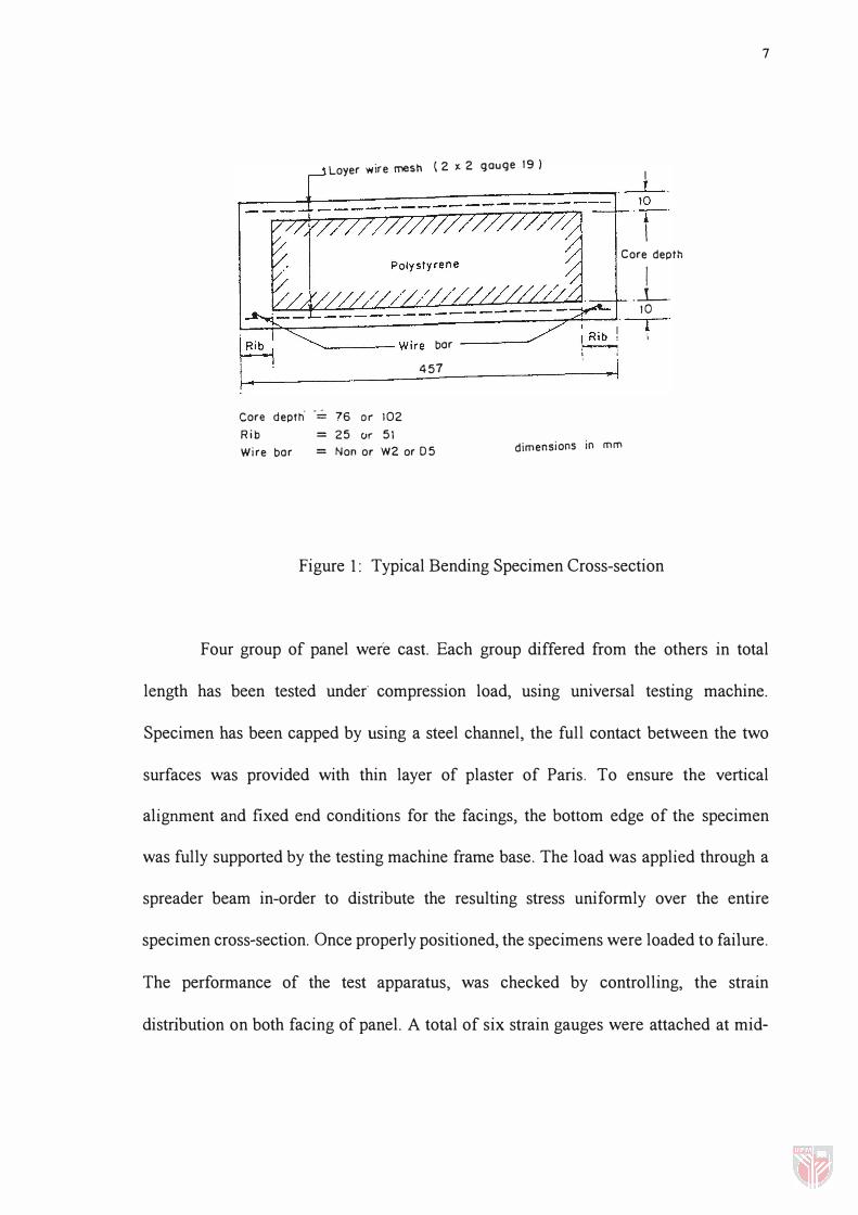
Nanni et al. (1986) carried out tests on ferrocement sandwich panels subjected
to bending and edge-wise compression load. Eight panels subdivided into two groups
were cast. A typical panel cross-section consisted of two ferrocement facings; 10 mm
thick reinforced with one layer of welded wire mesh is shown in Figure 1. The core of
the sandwich was made of a polystyrene sheet, laterally confined by mortar ribs.
Bending tests were carried out using a universal testing machine, with load and
deflection readings taken at pre-set load increments before cracking occurred, and pre
set deflection increments thereafter. Deflections were measured by using pairs of dial
gauges, at centreline and support locations.
Loyer wire mesh (2)(.2 gouge 19 ) I
�----4---------���==�====�==�'�' '-i -'
I Core depth
I .l-.
10
��=-=====-':"'-------;7--;--1 �' -r ' � I "'-----Wire bar ----
Core depth' -= 76 or 102
Rib = 25 or 51
457
Wire bar = Non or W2 or 05
I ,
�I
dimensions in mm
Figure 1: Typical Bending Specimen Cross-section
7
Four group of panel were cast. Each group differed from the others in total
length has been tested under' compression load, using universal testing machine.
Specimen has been capped by using a steel channel, the full contact between the two
surfaces was provided with thin layer of plaster of Paris. To ensure the vertical
alignment and fixed end conditions for the facings, the bottom edge of the specimen
was fully supported by the testing machine frame base. The load was applied through a
spreader beam in-order to distribute the resulting stress uniformly over the entire
specimen cross-section. Once properly positioned, the specimens were loaded to failure.
The performance of the test apparatus, was checked by controlling, the strain
distribution on both facing of panel. A total of six strain gauges were attached at mid-
8
length of the specimen. The result indicates that for specimens of identical cross-section
the load bearing capacity decreases when the length of the specimen increases.
Moreover, instability of the facings governs the ultimate capacity of sandwich panels
subjected to uniform in-plane compressive load.
Davies (1987) analysed sandwich panels, consisting of metal faces and a rigid
foam core, subjected to combine axial compressive load and bending moment using
fInite element method. In addition to the theoretical analysis, two profIles were tested,
denoted as profIles A and B. Panel A was tested in both bending and axial compression
whereas panel B was tested in axial compression only. From bending tests on panel A,
the load deflection has been obtained then the value of the apparent flexural rigidity EI
was determined. The corresponding theoretical curves were obtained for various values
of the core shear modulus. The comparison between the experimental and theoretical
value of EI is given in Figure 2, from which it can be deduced that the average value of
G in the tested panels was 2 Nlmm2.
Three tests on panel B were carried out with nominal eccentricities of 0 mm, 57
mm and 114 mm, respectively. It has been observed that the eccentric loading has a
profound influence on the results. The failure load reduces dramatically with increasing
eccentricity.