universiti malaysia pahang faculty of …umpir.ump.edu.my/95/1/thesis complete.pdf · the thesis...
TRANSCRIPT

i
UNIVERSITI MALAYSIA PAHANG
FACULTY OF ELECTRICAL & ELECTRONICS
ENGINEERING
THESIS
HAND GESTURE RECOGNITION SYSTEM
USING IMAGE PROCESSING
ABANG IRFAN BIN ABANG ABDUL HALIL
SUPERVISOR:
ROSDIYANA SAMAD
SEMESTER 2007/2008

UNIVERSITI MALAYSIA PAHANG
JUDUL
SESI PENGAJIAN: 2007/2008
Saya _ABANG IRFAN BIN ABANG ABDUL HALIL (850615-13-6029)___
mengaku membenarkan tesis (Sarjana Muda/ Sarjana /Doktor Falsafah)* ini disimpan di
Perpustakaan Kolej Universiti Kejuruteraan dan Teknologi Malaysia dengan syarat-syarat kegunaan
seperti berikut:
1. Tesis adalah hakmilik Kolej Universiti Kejuruteraan dan Teknologi Malaysia.
2. Perpustakaan Kolej Universiti Kejuruteraan dan Teknologi Malaysia dibenarkan
membuat salinan untuk tujuan pengajian sahaja.
3. Perpustakaan dibenarkan membuat salinan tesis ini sebagai bahan pertukaran antara
institusi pengajian tinggi.
4. **Sila tandakan ()
SULIT (Mengandungi maklumat yang berdarjah keselamatan atau
kepentingan Malaysia seperti yang termaktub di dalam AKTA
RAHSIA RASMI 1972)
TERHAD (Mengandungi maklumat TERHAD yang telah ditentukan oleh
organisasi/badan di mana penyelidikan dijalankan)
TIDAK TERHAD
Disahkan oleh
_________________________ ___________________________
(TANDATANGAN PENULIS) (TANDATANGAN PENYELIA)
Alamat Tetap: No 305, Jalan Delima 4 Nama Penyelia: ROSDIYANA
Lot 144, 24000 Kemaman SAMAD
Terengganu
Tarikh: 26 NOVEMBER 2007 Tarikh: 26 NOVEMBER 2007
CATATAN: * Potong yang tidak berkenaan.
** Jika tesis ini SULIT atau TERHAD, sila lampirkan surat daripada pihak
berkuasa/organisasi berkenaan dengan menyatakan sekali sebab dan tempoh tesis ini
perlu dikelaskan sebagai SULIT atau TERHAD.
Tesis dimaksudkan sebagai tesis bagi Ijazah Doktor Falsafah dan Sarjana secara
penyelidikan, atau disertai bagi pengajian secara kerja kursus dan penyelidikan, atau
Laporan Projek Sarjans Muda (PSM).
HAND GESTURE RECOGNITION SYSTEM
USING IMAGE PROCESSING

iii
“I hereby declare that I had read this thesis and in my opinion this thesis is sufficient
in terms of scope and quality for the purpose of the granting of Bachelor of Electrical
Engineering.”
Signature : ………………………………………
Name of Supervisor : Rosdiyana Samad
Date : ……………………………………....

iv
HAND GESTURE RECOGNITION SYSTEM USING IMAGE PROCESSING
ABANG IRFAN BIN ABANG ABDUL HALIL
"This thesis is submitted as partial fulfillment of the requirements for the award of the
Bachelor of Electrical Engineering (Power Systems)"
Faculty of Electrical Engineering
Universiti Malaysia Pahang
26 NOVEMBER 2007

v
DECLARATION
I declare that this thesis entitled “HAND GESTURE RECOGNITION SYSTEM USING
IMAGE PROCESSING” is the result of my own research except as cited in references.
The thesis has not been accepted for any degree and is not concurrently submitted in
candidature of any other degree
Signature : _______________________________________
Name of candidate : ABANG IRFAN BIN ABANG ABDUL HALIL
Date : 26 NOVEMBER 2007

vi
DEDICATION
To my beloved mother and father
Abang Abdul Halil bin Abang Naili
Zaiton binti Yusof
My fiancée for waiting me to finish this before doing hers
My supervisor who exposed me to this wonderful piece of engineering

vii
ACKNOWLEDGEMENT
First of all I am grateful to ALLAH S.W.T for blessing me in finishing my final
year project (PSM) with success in achieving my objectives to complete this project.
Secondly I want to thank my family for giving morale support and encouragement
in completing my project and also throughout my study in University Malaysia Pahang
(UMP) as they are my inspiration to success. I also would like to thank my supervisor
Rosdiyana Samad for guiding and supervising my final year project throughout these two
semesters. Shee has been very helpful to me in finishing my project and I appreciate
every advice that she gave me in correcting my mistakes. I apologize my supervisor if
any mistakes and things that I done wrong while doing my project. My credit also goes to
Mr Professor Madya Shaikh Nasir Shaikh Abd Rahman as the dean of Electrical
Engineering Faculty and Mr Addie Irawan Hashim as the coordinator of final year project
with their cooperation and guide about my final year project from the beginning.
Last but not lest I want to thank all my friends that have gave me advice and
encouragement in completing my project. Thank you very much to all and May ALLAH
bless you.

viii
ABSTRAK
Pemprosen imej mempunyai potensi yang besar untuk boleh melakukan hampir
apa sahaja. Tetapi dalam kehidupan sebenar ianya diburukkan lagi dengan keadaan
apabila pembangunan sesuatu bidang yang diminati tidak dilakukan dengan teratur.
Projek ini menampilkan sehingga terperinci pembangunan sistem pengecaman dengan
menggunakan perisian pemprograman grafik NI LabVIEW. Ia kompleks dan boleh
diubahsuai dalam banyak cara untuk sistem hiburan hari ini untuk kembali membawa kita
kepada asas keselamatan. Ianya tidak berguna mempunyai suatu sistem yang lengkap
tetapi mengabaikan keselamatan manusia. Justeru, untuk mencapai sama tinggi dengan
pencapaian teknologi hari ini, projek ini akan cuba membawa teknik-teknik rumit imej
pemprosesan sebagai penyelesaian kepada penyampaian arahan dalam bentuk yang lain.
Perkakasan projek ini disambungkan menggunakan Kit Pembangunan Perisian, SDK
daripada pembuat perkakasan tersebut, iaitu bagi projek ini Logitech Inc.. Penyaluran
data yang teratur di antara perkakasan dan perisian memastikan transaksi yang licin yang
meningkatkan prestasi dan kebolehannya. Kaedah pencahayaan belakang juga digunakan
untuk memberikan exposure yang sesuai kepada subjek supaya pemprosesan seterusnya
dan analisis blob (objek besar binary analisis) boleh dilakukan. Sistem ini juga
menggunakan algoritma daripada beberapa teknik pemprosesan yang mungkin atau tidak
memberikan keluaran yang sama untuk setiap satunya. Sistem ini mampu dinaik taraf
dengan memasangkan ia secara modul-modul berasingan. Ia mungkin tidak sesuai
dilakukan hari ini, tetapi dengan harga perkakasan kecil yang semakin menurun ditambah
pula dengan sedikit inovasi seperti pencahayaan infra merah, 0 lux acquisition
penglihatan malam, imej pemprosesan dan teknologi logic fuzzy untuk sentiasa melatih
mesin, ia akan menjadi suatu kemestian harian kelak. Ini terbukti apabila menimbang
penyelidikan dan pembangunan berjuta ringgit teknologi Beg Udara contohnya, satu
masa dahulu kini menjadi satu keperluan.
ix
ABSTRACT
Image processing has a very big potential to do virtually anything. But in real life,
worse come to worst when the development of particular interest is not being done
properly. This project comes to the extent of development details on recognition system
by using state-of-the-art NI LabVIEW graphical programming software. The
complexness and configurable in so many way of today’s entertainment has brought us
back to basic of safety. It is worthless to have a complete system that can do almost
anything but compromises human life. To cope up on par to today technological
achievement, this project will try to bring sophisticated ways of using image processing
as a solution to deliver command in the other way. The hardware is being interfaced by
using Software Development Kit (SDK) from the supplier of the hardware, in this case is
Logitech Inc. Proper data channeling between hardware and software ensure smooth
transaction that increase performance and capability. The method of backlighting is used
to give proper exposure to the subject so that the further processing and blob (binary
large object) analysis can be done on it. This system also used algorithm of several
processing technique that may or may not be the same output for each type of it. The
system is upgradeable to be connected by separate module. It will not be viable to
implement it today, but the ever falling prices of gadget plus a little bit of innovation into
infrared lighting, 0 lux night vision acquisition, refine image processing and fuzzy logic
to keep the system trained, it will be everyday must. This is proven, considering costly
research and development on Air Bag technology as an example, sometimes ago is now a
necessity.

x
TABLE OF CONTENTS
CHAPTER TITLE PAGE
TITLE i
DECLARATION iii
DEDICATION vi
ACKNOWLEDGEMENT vii
ABSTRAK viii
ABSTRACT ix
TABLE OF CONTENT x
LIST OF TABLE xiii
LIST OF FIGURE xiv
LIST OF ABBREVIATION xvii
LIST OF SYMBOLS xviii
LIST OF APPENDICES xix
1 INTRODUCTION 1
1.1 Background 1
1.2 Project Objective 2
1.3 Project Scope 3
1.4 Structure of This Thesis 3
2 LITERATURE REVIEW 6
2.1 Introduction 6
2.2 Deadly distraction 7
2.3 Human Interface Devices 8
2.4 Hand Gesture 9
2.5 Image Processing 10

xi
2.6 Machine Vision 12
3 METHODOLOGY 14
3.1 Introduction 15
3.2 Key Working Component 17
3.2.1 Hardware 17
3.2.1.1 Web Camera
3.2.1.2 Data Acquisition Card
3.2.1.3 Protocol & Standard
3.2.1.4 Usable Resources
3.2.1.5 Addressing Issue - Parameter
3.2.1.6 Advantech Data Acquisition Card
3.2.1.7 Protocol & Standard
3.2.1.8 Autotronic’s Triggered MP4 Player
3.2.2 Software 32
3.2.2.1 National Instrument LabVIEW 8.2
3.2.2.2 Measurement & Automation Explorer 3.0
3.2.2.3 NI Vision Development Module 8.2
3.2.2.4 NI Vision Assistant 8.0
3.2.2.5 Vision Builder 2.5
3.2.2.6 NI IMAQ for USB Camera
3.3 Preparation of Optimal Imaging 39
3.3.1 Backlighting Effect 39
3.4 Process of Acquisition 42
3.4.1 Initialize 44
3.4.2 Acquire 45
3.4.3 Use data 45
3.4.4 Dump 46
3.5 Pre-processing & Processing 46

xii
3.5.1 Pre-processing 48
3.5.2 Processing 52
3.6 Feature Extraction 53
3.6.1 Conversion Process 54
3.6.2 Find Circular Edge 55
3.6.3 Pattern Matching – Fingertip 56
3.6.4 Pattern Matching – Others 59
3.7 Decision Making 61
4 RESULTS & DISCUSSION 71
4.1 Results 71
4.1.1 System Performance 71
4.2 Discussion 71
4.2.2 System Limitation 75
5 CONCLUSIONS 78
5.0 Introduction 78
5.1 Future Recommendation 79
5.2.1 Cost & Commercialization 79
REFERENCES 82
Appendices A 84
Appendices B 86

xiii
LIST OF TABLES
TABLE NO TITLE PAGE
1 RGB composition of human skin 41
2 Decision making truth table 72
3 Feature extraction summary 74
4 Result for feature recognition 75
5 Result for gesture recognition 76
6 Cost impact 80

xiv
LIST OF FIGURES
FIGURE NO TITLE PAGE
1 - Graphical structure of this thesis 5
2 - RGB component and composites 11
3 - SDK version acquisition system 16
4 - Imaging device sensor 18
5 - Logitech QuickCam Pro 500 19
6 - VISA driver development wizard 22
7 - Basic device information window 23
8 - Hardware identification 24
9 - Output files properties window 25
10 - Step for installing hardware and software 27
11 - DAQ card 28
12 - Autotronics hardware 30
13 - Autotronics control circuit 31
14 - Measurement & Automation Explorer 34
15 - NI Vision Development Module 35
16 - NI Vision Assistant 36
17 - NI Vision Builder 37
18 - NI Vision Builder inspection mode 38
19 - Color picker 40
20 - Backlighting sample image 40
21 - Image under backlighting effect 41
22 - Snap program 42
23 - Grab program 43
24 - IMAQ Create 44
25 - IMAQ USB Grab Setup 44

xv
FIGURE NO TITLE PAGE
26 - IMAQ USB Grab Acquire 45
27 - Use data 45
28 - Dump memory 46
29 - Vision & Motion sub library 47
30 - Image processing Step 1 49
31 - Image processing Step 2 49
32 - Image processing Step 3 50
33 - Image processing Step 4 50
34 - Find circular edge 51
35 - Automatic y-coordinate cut 51
36 - Circular data and parameter 52
37 - Image processing Step 5 53
38 - Outside deviation circular 55
39 - Within deviation circular 55
40 - Within deviation circular with centre body 56
41 - Fingertip Detection Row 1 57
42 - Thumb recognized as fingertip 58
43 - Fingertip used as master template 58
44 - Three fingertips were detected 59
45 - Fingertip and circle 59
46 - NI LabVIEW coordinate system 60
47 - Two wedges with template 61
48 - A hole with template 61
49 - Front Panel of the system 62
50 - Gesture with additional feature 64
51 - Gesture of same image different orientation 65
52 - C1 and H1 universal decision making template 66

xvi
FIGURE NO TITLE PAGE
53 - Overall decision to LCD indicator 66
54 - Modified parameter 67
55 - Varying x and y coordinate 67
56 - Data cluster 68
57 - Improved decision making front panel 68
58 - Decision making program 69

xvii
LIST OF ABBREVIATION
ABBREVIATION
CCD – Charge Couple Device
CMOS – Complementary Metal Oxide Semiconductor
DAQ – Data Acquisition
DLL – Dynamic Linked Library
DVD – Digital Versatile Disc
HID – Human Interface Device
IMAQ – Image Acquisition
JPEG – Joint Photographic Experts Group
LCD – Liquid Crystal Display
MAX – Measurement & Automation Explorer
NI – National Instrument
PCI – Peripheral Computer Interconnect
PLC – Programmable Logic Control
PNG – Portable Network Graphics
PXI – PCI eXtensions for Instrumentation
RGB – Red Green Blue
SCR – Script
SDK – Software Development Kit
USB – Universal Serial Bus
VI – Virtual Instrument
VISA – Virtual Instrument Software Architecture

xviii
LIST OF SYMBOLS
Vdc - Dc Volts
Ω - Ohms

xix
LIST OF APPENDICES
APPENDIX TITLE PAGE
A Specification of Advantech PCI-1710 86
B Datasheet for NPN Darlington Planar Transistor 84

1
CHAPTER 1
INTRODUCTION
1.1 Background
This chapter covers literal explanations of Hand Gesture, Image Processing and
Machine Vision and how these processes brought recognition system into a whole new
level of versatility. It also briefly explains National Instruments LabVIEW software and
Vision Assistant of the advance G-Programming in practical application. The preceding
will give an overview of image processing project specifically in recognition, the
objective of the project, project scopes and thesis outline.
Machine will always be trained to replace human function in accomplishing
specific task. However, recognition is not as simple as comparing it to complex
mathematics operation. Computers only operate in discrete manner of 1 and 0, on and
off whereas human operate in analog and abstract manner. That is why understanding
analog system and abstract matters as deeply as possible will enable machine to do
vision tasks almost as precise as human own capability.

2
Image processing is a branch of knowledge that tries to reach the same goal as
human vision does. The process will not be the same but the objective is. The concept
may or may not differ, depends on what sub task of the whole system is to be
accomplished first. Machine look on something trough segregated details to do matching
based on system’s hardware capability. Human on the other hand, used as much
information as possible and will decide at that instance, fulfilling directly to the
objective of the vision task itself. That is why trying to have the same par with human
capability especially from the recognition accuracy perspective is impossible with
current technology advancement available.
This project develops an alternative human interface from web camera input.
Further, this system will execute a set of playback instruction on a model of car audio
playback function. This project will be build by using LabVIEW Image Processing
Software where block diagram programming is present. It is so far the easiest to program
and troubleshoot through available step by step simulation function within.
This project is build to help drivers operate in car entertainment option. The most
distracted event is when there is an incoming call from the driver's mobile phone. As
reflect to that research by Volvo, the problem of divers distracted from focusing on the
road is issue to be taken care of. Distraction in certain cases can lead to collision and
loss control over the vehicle.
1.2 Project objective
The objective of this project is:-
i. To develop a hand gesture recognition system
ii. To develop a system that can translate snapshot of hand gesture to a set of
playback instruction on a model of car audio playback function.

3
1.3 Project scope
Below are the scopes that to be proposed for this project:
i. To develop an image acquisition system that automatically acquire for a fixed
interval of time or when the gestures are present.
ii. To develop a set of definition of gestures and processes of filtration, effect and
function available.
iii. To develop a pre-defined gestures algorithm that command computer to do
playback function of car audio model. This include Play, Stop, Pause, Fast
Forward, Fast Backward, Volume Decrease, Volume Increase and ON/OFF
function.
iv. To develop image processing analysis system to be later used in feature
extraction.
v. To develop a testing system that proceeds to command if the condition is true
with the processed images.
vi. To develop a simple Graphical User Interface for input and indication purposes.
vii. To interface acquisition hardware and software on a laptop computer until
completion.
1.4 Structure of this Thesis
This thesis composed of 5 chapters each will detail out of details upon every
aspect of this project. This project also being completed step-by-step chronologically
order as how to easily setup any system together with National Instrument’s software to
do machine vision.
The beginning of this thesis will explain on what foundation the system to be
built on. This includes Chapter 1 as the intro of the whole thesis. The preceding chapter
2 will touch on why this project was proposed.

4
Next, chapter 3 will explain how to have a complete setup for machine vision
application. This chapter started with overview in sub chapter 3.1 and sub chapter 3.2 on
key component of software, hardware and how both should cooperate. Then it is
followed with a further look on the overall system built. These topics will detail out
everything under the interest of the system itself excluding the setup explained earlier in
chapter 1. Sub chapter 3.3 will explain optimum imaging environment followed by sub
chapter 3.4 that will explain in detail regarding acquisition where National Instruments
are very good at. Sub chapter 3.5 will touch one by one everything about processing in
LabVIEW environment, whether it is a pre-processing for getting image to full
processed or processing to enhanced feature extraction process. Sub chapter 3.6 will
have a brief look on feature extraction. Sub chapter 3.7 will take a look on decision
making. The last part of this thesis is to discuss on the overall of the finished product.
This chapter 4 started of with results and discussion of the system including performance
on sub chapter 4.1.1.
This thesis will properly be concluded in the last Chapter 5 followed by
recommendation for the extension of this project and future prospect for the
development room of improvement to grow on.

5
Figure 1: Graphical outline of this thesis
Processing
x
Image Acquisition
Optimal Imaging
Feature Extraction
on
j1 j
2 A
y
SETUP > SNAP > PROCESS > ANALYZE > DECIDE
opt shot > input > clean image > recognized > output
Component
Kor
rela
tion k
m
ax
,
d
1
.
0 0.
92
11
34
2
1
0.
36
54
31 0.
22
02
19 0 0 1
2
7 Se
gme
nt
Output Signal
Decision
Making Signal

6
CHAPTER 2
LITERATURE REVIEW
2.1 Introduction
As early as in 1670, there’s an expertise for human eyes named optometrist to
help its patient to have a better vision on their surrounding. The first one is Benjamin
Franklin that invented the first pair of bifocal glasses [1]. Benjamin’s intention is to
improve visibility and at that time not to aid people with sight problem like most people
today. That context is referring to human capability of seeing things, contributing to a
very highly valuable gift. Thanks to the fine creation of god, we do have two eyes that is
one of tool to predict and act verily according to the vision tells and guides.
Just imagine how this world is if we are normal human being with healthy eyes,
then we lost the vision or capability of capturing images and color. Even with one eyes,
we have difficulties of estimate the distance of an object. Then, we immediately lost
coordination and physical sense of everything around us. This situation best describe by
having woman protect herself from strangers just by spraying chili aerosol to paralyze its
attacker vision for a moment.

7
We cannot deny that we really dependent to our natural sensors. Lacking or not
properly operational sensors can cause difficulties to our life. One of the important
activities that most people do is to drive a vehicle. No blind man can drive a vehicle, it is
just unacceptable. Researchers and technologist see this by first try to create self driving
cars that enable to ease our life. This is considered after the growing and more
entertainment option available for in car experience. If we can try to imagine a perfect
working system for it, it will of course an invention of the centuries that really have a
high impact on our life culture. But when thinking over these, to have this is just a long
way to go. It will be available, but sure it will not available for quite sometimes as the
progression on the vision technology is slowly developing.
2.2 Deadly Distraction
So, to come back to that very point, modeling and copying the vision system of
human sight to work exactly like it naturally does. We imitate human sight system to
have it done the same objectives, vision with a more reasonable and achievable way.
That is why this project is being proposed. This project came from idea of minimizing
distraction to car driver when they drive, that’s it. Distraction even if it is just for a short
while will endanger the driver from focusing on the road. The most distracted event is
when there is an incoming call from the driver's mobile phone. As reflect to that research
by Ford, it is clear that a driver who is driving while operating car audio equipment can
get distracted from focusing on the road.
Early production of automotive built quality is poor. Company at that time did
not want to discuss about safety. They did not remind their customer they can get hurt in
these things (automobile) [2]. As time goes by, safety is considered as a taboo subject no
more. By just a little bit of ongoing knowledge acquisition plus innovation here and
there, it is considered as a life improvement and rewarding business. Today, company
such as Volvo have stand out of crowd just because of their niche to be the safest car
available on earth.

8
As for commercializing for this type of systems, having company making money
just to improve safety for people is a very mutual profit process. There will be a team of
people help to design and built safety function for the purpose of commercialization.
The drivers as the end users can get benefit out of the noble deeds as well, thus
improving safety level and comfortableness of life. Because of these continuing activity,
automotive manufactured up to this date is much safer and refined than model available
at the past.
This project has a few specific region of advancement to help not only aided
driving but also to be implemented elsewhere. It is known that the implementation of
this project to current automotive industries maybe is not feasible and practical. Thus
there is a few usability of this project even it is not being implemented in automotive
industries. To help understand better for that point, it is better for us to understand
gestures literally and then the final result of this project is hoped to be.
Thus, this project will build a model of gestures operated car audio systems, a
smart solution for a trouble free driving. As we look deeper, gestures have been
researched by most intellectuals to strengthen the opinion of how useful gesture is. To
look ahead on this, there is a need here to inform readers gestures have been researched
by sociologist and biologist. And the other party is engineering student like me, to
further enhance human hand capability to create and provide spectrum of command to
machines.
2.3 Human Interface Device
A human interface device or HID is a type of computer device that interacts
directly with and most often takes input from humans and may deliver output to humans
[3].
Common HIDs are:-

9
Keyboard
Mouse, Trackball, Touchpad, Laptop eraser
Graphics tablet
Joystick, Gamepad
The working group named as the Human Interface Device class at the suggestion
of Tom Schmidt of DEC because the proposed standard supported bi-directional
communication.
To have interactive input device is important to meet up problems come with it.
For example using remote control is very handy. But by losing the remote control
device, the purpose of easing started to disappear. Another example yet different
perspective is to have a very dynamic system that can be configured programmatically
instead of hardware mending.
2.4 Hand Gesture
When we look in a wider extent, gestures came out from human body is natural.
From Concise Oxford English Dictionary, gesture is a movement of part of the body,
especially a hand or head, to express an idea or meaning [4]. As for this project, the
development portion is to develop a new practical technology for alternative human
interface. This gesture definition has been narrowed down to only hand and is given
particular attention on details that Asian hands has.
Human do most things by using hand. The uniqueness covers from picking the
smallest object to even do specialize work or even giving meaningful gestures to convey
information. Take traffic police for instance, by just moving his hand and come out with
different gesture each explaining go, stops or wait to the drivers.

10
2.5 Image Processing
Image processing is any form of information processing for which the input is an
image, such as photographs or frames of video; the output is not necessarily an image,
but can be for instance a set of features of the image. Most image-processing techniques
involve treating the image as a two-dimensional signal and applying standard signal-
processing techniques to it [5].
It is clear that image processing do have some kind of manipulation towards
what it is fed to do. LabVIEW in their concept manual describe Image Processing as
functions to analyze, filter and process images in NI Vision [6].
A pixel, short for picture element, can be thought of as a tiny dot containing
information about the picture. When you snap a picture, these tiny bits of information
are gathered by the camera's sensor [7]. The information is being stored in a 3 plane of
information. Each plane represents three colors that are red, green and yellow plane.
Each plane has the intensity from 0 up to 255 or 8-bit of information per plane. These
three color combination makes up all the color we could see in an RGB images.
Simple calculation of this are 8-bit information is as follow:-
2n = bit, 28 = 256
The origin of this size started when the byte was introduced back then in the
origin of information capacity now have its standard. Many of the techniques of digital
image processing, or digital picture processing as it was often called, were developed in
the 1960s at the Jet Propulsion Laboratory, MIT, Bell Labs, University of Maryland, and
a few other places, with application to satellite imagery, wire photo standards
conversion, medical imaging, videophone, character recognition, and photo
enhancement [8]. Digital processing is most of the time preferable because of cost issue
on top of falling trend of digital devices.

11
Computers are getting cheaper and more affordable to own by anyone starting in
the 1970s [9]. The image processing styles emerge up to processing it in real time using
appropriate image acquisition hardware. That is generally when television start to be
invented and marketed to home user.
Images could then be processed in real time, for some dedicated problems such
as television standards conversion. As general-purpose computers became faster, they
started to take over the role of dedicated hardware for all but the most specialized and
compute-intensive operations [10]. With the fast computers and signal processors
available in the 2000s, digital image processing has become the most common form of
image processing, and is generally used because it is not only the most versatile method,
but also the cheapest.
There are many types of image processing available today. Typical image
processing is grouped into Processing, Filters, Morphology, Analysis, Color Processing,
Operators and Frequency Domain. While these groups are referring to only image
processing available on National Instrument platform, narrowed down to some wide
feature available. These image processing named only available with installation of
LabVIEW 8.2 together with compatible NI Vision Development Module.
Figure 2: This image demonstrate Extract Plane image processing on an RGB image.
The picture shows red, green and blue color channel over composite as image at the last

12
2.6 Machine Vision
Machine Vision is where machine are used to see, evaluate at the same time
giving output as what human ought to give. Traditionally this is accomplished by human
workers where repetitive heavy production environment and high tense situation take
place. Because of human have feelings, quality are often vary most of the time.
This section describes conceptual information about high-level operations
commonly used in machine vision applications such as edge detection, pattern matching,
dimensional measurements, color inspection, binary particle classification, optical
character recognition and instrument reading [11]. Machine vision will be explained in
details in chapter 3.6, feature extraction. In addition, processing in sub chapter 3.5.2 is
also indirectly mentioning processing for feature extraction purposes.
Among what machine vision can do are as follows:
Edge Detection
Pattern Matching
Geometric Matching
Dimensional Measurement
Color Inspection
Binary Particle Classification
Golden Template Comparison
Optical Character Recognition
Instrument Readers
In test and measurement applications such as movement measurement and event
recording, and result verification, you can easily integrate and correlate images with
transducer-based data acquired with data acquisition hardware [12]. Manufacturing plant
with a very tight production schedule to be met along with quality control will usually
require a lot of attention of many. The workers are also being paid accordingly with a
very large number of workers.

13
It is clear machine should be used and replace human in so many attention as it
do not retaliate and do very forward to what being asked for. In industrial application,
vision analysis routines test incoming images part quality. Overall, computer vision are
more reliable and cost-effective than human workers in the high-speed, detailed,
repetitive manufacturing processes required for making semiconductors, electronic,
medical, pharmaceutical and computer products [13].
Machine often cost more in most automated application, requires maintenance
attention and competent operator to monitor its operation. In contrast, machine vision’s
benefit can be fully utilized even with a very cheap setup, almost no maintenance and
very little attention to as it is fully automated. This makes machine vision desirable over
anything else yet still delivers cost-effectiveness. The only catch lies on the development
of the system. On that solid ground, this project is being proposed.

14
CHAPTER 3
METHODOLOGY
3.1 Introduction
This chapter will be dedicated to explain the system in great details from setting
up, to the system component to the output. The working component of this system
consists of 5 different parts where most of the techniques have been simplified to ease
presentation. These techniques include hardware and software setup, image acquisition,
image processing, feature extraction and decision making modules.
The key working component sub chapter 3.2 will explain hardware and software
requirement including available option in spite of limitation found. In sub chapter 3.3 is
the method used for having optimal imaging. Very much effort in preparing the
hardware will ease processing in software. Then the image acquisition in sub chapter 3.4
will briefly describe process of acquisition as it is not as simple as most people would
think of especially the interfacing parts that is partially describe in sub chapter 3.2
earlier. Next are details of pre and post processing to all needed and optional processing
needs explained in sub chapter 3.5. Also included the critical feature extraction and
decision making module at chapter 3.6 and 3.7 respectively.

15
3.2 Key Working Component
This project is a development of system that consists of software and hardware
section. Software and hardware details will be explained afterwards. After all
programming stages completed, the last stage is to have hardware and software
interfaced together. At that time, if the hardware fails to perform as it should, problem to
the image acquisition stage will bring the biggest disaster.
It is undeniable the biggest part in this project is on the software side. Software is
very crucial to have it work harmoniously afterwards. The software parts also includes
abundant of programming and small scale detailing. The software parts also take most of
the time to be slowly developed. At this stage, at the interfacing stage will be the most
challenging as well. So it is a very big responsibility to make all of it, software and
hardware working together to deliver desire result as a proof of application of research
inside this project.
This project takes quite a long time to settle interfacing. Interfacing at the end
line become more and more complicated as it’s approaching to know what Logitech
have in mind when they first write the web camera driver. Researching for an easier
option has lead this project to the usage of Software Development Kit (SDK) provided
by Logitech instead. The SDK is made available for people that already have the
programming skills to use it [14].
These long searches have returned a few limitations towards writing image
processing language in the fastest. CCD cameras are often expensive and their bundled
software development kits (SDK) typically are proprietary, involve licensing and
royalties. Beyond affordability, such SDKs often just provide ActiveX components and
not the source code. As such, developing your custom application is limited to what

16
functions the SDK gives you [15]. Image processing is not short but it is complicated in
order to function properly, or at least to do minimum machine vision tasks.
Figure 3: The SDK version acquisition system works fine in LabVIEW 6.0
The last solution is to have the LabVIEW 8.2 evaluation version along with NI
Vision Development Module 8.2, NI IMAQ for USB Devices. This solution is risky and
has a very limitative to what programmer can do. The evaluation version is fully
functional for only 30 days. It will ask for license key after the interval has elapsed. This
project utilized the evaluation software fully when it is capable of doing what a normal
version can such as saving a VI files and vision assistant SCR files.

17
Please use recommended hardware to confirm the result for demonstration CD
provided with this thesis. For Software Development Kit Demo, please find
LabVIEW_Logitech_SDK_Acquisition_Demo.zip file to start of on a LabVIEW 6.
Unfortunately, this thesis does not provide such software version in complementary CD
but can be opened by newer LabVIEW 7 and above, however functions and wiring seem
to be slightly different. Thus, most of the demo VI files are unusable.
3.2.1 Hardware
From The Free Dictionary by Farlex tells us that visual system is the sensory
system for vision [16]. One of the most important thing in having a complete system that
can see, as reflect to the word ‘visual’, is to have a sensory system that enable visual
being processed and sent into brain to draw vision. As an introduction to the machine
world, the word sensor once again is very close to web camera or the hardware used for
this complete system. As human physiology, a pair of eyes functions as a color collector
and being processed as an image.
This project used a web camera as an input device. To help better finishing this
project without due and probable problem caused by interfacing of hardware and
software, this project have been accomplished by phase. Each phase represent a portion
of the system’s development. At the end of each phase, it will be directly tested on a
complete system consisting of hardware and software interfaced altogether.
To have the system work, some image processing function that involves IMAQ
function wouldn’t work if there is no hardware attached to it. Hardware attached to the
computer will need to be first calibrated and configured to the laptop machine in order to
work. In LabVIEW, the program stops running and display error message if this
condition happened.

18
For computer to run the program and process it, this project uses Toshiba
Satellite L20-C430 laptop. The demo will be using the same hardware also. The machine
is equipped platform on Celeron processor and 256MB of RAM with National
Instrument LabVIEW Software plus National Instrument IMAQ function installed.
3.2.1.1 Web camera
Web camera captures motion images with resolution 640 times 480 pixels and
capability capturing 30 frames per seconds. Preliminary, this particular camera can go
up to 25 frames per second only. Now, the capability is bigger and not impossible to
increase in the near future. To enhance the capturing ability, the camera used is using
CCD as a sensor. CCD stands for Charge Couple Device, which is not regarded as more
superior against CMOS or Complementary Metal Oxide Semiconductor type of sensor.
With three layer of CCD, each capturing each plane consisting of Red, Blue and Green
respectively giving a more vibrant and sharp images. This factor also contributing to the
resolution and frames per second performance on capturing images. CCD is less prone
to noise.
(a) (b)
Figure 4: (a) CCD Sensor and (b) CMOS Sensor

19
Newer model such as QuickCam Pro 5000 that have capability of acquiring 30
frames per second and still image for about 1.2 megapixels. With the bundled, it is
known it have software enhanced to help lighting condition. As for point of view, it will
not be used as it will be using differently type of program and be configured to be used
later by NI Explorer.
Figure 5: Logitech QuickCam PRO 5000
The hardware requirement should be enough to have it processed 25 to 30 frames
per second. Even tough there are a better hardware for imaging purposes such as IEEE-
1394 firewire camera, line scan camera or line area camera, this hardware serve it
function and its ability far exceed what software can do. The limitation is around
software, thus hardware is not much a concern.
3.2.1.2 Specification
Logitech Web Camera
Name: QuickCam Express
Manufacturer: Logitech Inc.
Resolution: 352 X 244 pixel
Sensor Type: Charge Couple Display (CCD)
Interface Type: Universal Serial Bus (USB)
20
Please have a look on Appendix 1 for detailed hardware specification provided the
manufacturer.
3.2.1.3 Protocol & Standard
To have a successful connection between LabVIEW and USB hardware, there is 4 ways
of doing it as listed below:-
Use a third party driver: These resources of hardware were provided by advance
programmer professionals. This is mostly valid to open source user since the
unavailability of hardware drivers is a common scenario.
Control and acquire data from the camera by calling the camera's DLL files.
Write your own drivers for the camera using VISA. There are several helpful
resources.
Download and install NI-IMAQ for USB Cameras: Due to the software provided
is not govern by National Instrument supports, thus the availability to wide
variety of manufacturers are also limited.
3.2.1.4 Usable Resources
To make it workable within LabVIEW environment, particular hardware is to be
reserved from others party utilization. LabVIEW needs the particular hardware to be
communicating directly to it. By having this, any manufacturer application will not be
able to be utilized except by using manufacturer’s DLL driver by using call library
function. However the steps are not easy by using NI-VISA.
Some manufacturer will not make their source code available to public.
However, by the demanding customized application, popular brand like Logitech make
SDK, Software Development Kit instead. By having this particular kit, end user

21
especially advanced user who have the capability to do further programming can benefit
all capability of said hardware to their own application.
4.2.1.5 Installation of NI-VISA Details
All hardware has their own unique ID to differentiate it with one another. All
hardware must be addressed accordingly to have computer know what to find and what
information to acquire out of it. Simply by understanding it is an imaging device, the
information of how it require different from one another. Such as web camera, can
acquire video and images from it that normally can be accessible anytime without
problems. Scanner is a different story, there is a need to tell the scanner to do the
scanning first before it can be acquired or else no image can came out of it.
This subchapter wills details out how to use install hardware with National
Instrument VISA’s driver. VISA stands for Virtual Instrument Software Architecture.
All driver under Windows Xp environment used INF files whether it is provided by
manufacturer or other party. These simple guidelines will explain how to create an INF
File using the Driver Development Wizard. This INF file will be replacing windows
provided INF and this will enable hardware directly communicated with LabVIEW
software during the development of the recognition system.
The best part of using VISA is to have all interfacing standards to work along
with the same kind of driver. For example, a motion controls system that is being used in
conjunction with hardware. The software behaves the same. It is known that different
interfaces have different way to communicate with computers. By having VISA, all the
hardware will have no what problem so ever if being used different interface. For
example a system is being developed to communicate with hardware through serial
connection. Because of having USB in portable computer instead of traditional serial
interface, using VISA could make the connection works even though the new connection
is USB instead of normal serial D9 connection.

22
To use NI-VISA, you must first tell Windows to use NI-VISA as default driver
for the device. In the Windows environment, you can do this with an INF file. NI-VISA
3.0 and higher includes the VISA Driver Development Wizard (DDW) to create an INF
file for your USB device.
To open the DDW, select Start»Programs»National Instruments»VISA»VISA
Driver Developer Wizard. Figure 1 shows the open screen.
Figure 6: VISA DDW Hardware Bus Window
23
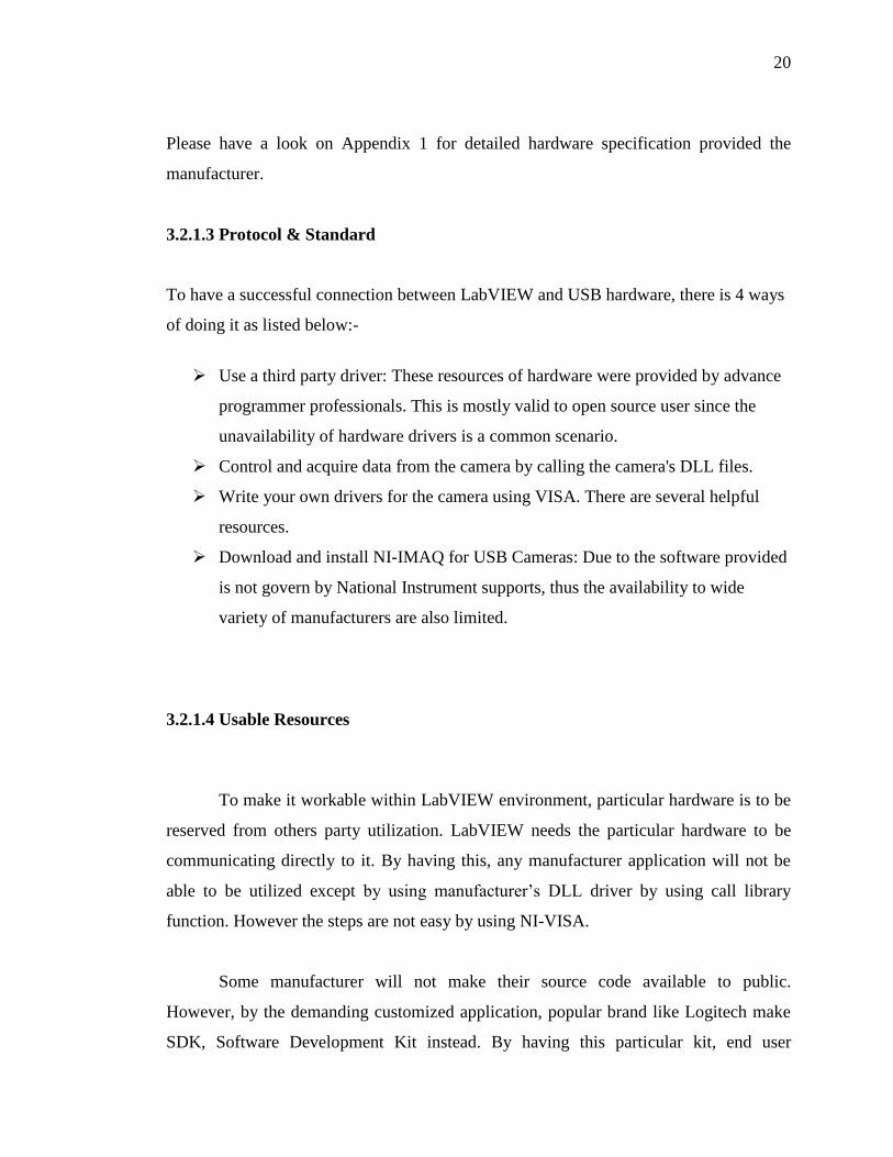
This wizard is used to create an INF file for a PXI/PCI, USB, or FireWire device.
Because you are creating the driver for a USB device, click USB and Next. The VISA
DDW Basic Device Information window opens as shown in Figure 2.
Figure 7: VISA DDW Basic Device Information Window
For this step, the USB vendor ID and product ID for USB hardware must be
known to address the right peripheral. These numbers identify the particular USB device
when you install it and address your device when you want to communicate with it.
According to the USB specification, both numbers are 16-bit hexadecimal numbers and
should be provided by the device manufacturer. The demonstration above is directly
taken from the Windows Xp Home Edition environment where Microsoft’s software

24
automatically detects and addresses the web camera hardware. This information is being
reused to configure NI-VISA to be available on MAX.
The recognition takes seconds when the hardware is plugged in. This has lead to
the usage of latest VISA driver available free to download in national instrument’s
websites. The information appear in the Device Manager from the Control Panel and
find your device on the list. Usually it is indicated as "Other Devices". The Logitech
driver apparently was readily available under Xp environment. Double click the device
to open the properties. Select the Details tab and ensure that "Device Instance Id" shows
in the attribute dropdown box. A string of characters will be displayed similar to Figure
10. The four characters to the right of "VID_" and "PID_" indicating vendor ID and
product ID, respectively.
Figure 8: Vendor ID and Product ID appear in Windows Xp Device Manager

25
The Logitech QuickCam Express came with Vendor ID of 046D and Product ID
of 0870. These prefix is shown in hexadecimal format. Enter the vendor ID, product ID,
manufacturer name, and model name for your device into their respective field. Click
Next. The Output Files Properties window is displayed as shown in Figure 11.
Figure 9: VISA DDW Output Files Properties Window

26
The USB instrument prefix is simply a descriptor you use to identify the files
used for this device. Enter a USB instrument prefix, select the desired directory in which
to place these files, and click next. The next window will provide you installation
options. The default selection is to install the setup information for the operating system
and is usually the best option. Once you select an option, click Finish to exit the wizard.
The INF file is created in the directory you specified in the output file directory field in
the previous window. Install the INF files and the respective USB device.
3.2.1.6 Advantech Data Acquisition Card
These are among the feature available for a DAQ card. DAQ card is very to get along
with as it has input and output specifically for advance electrical application to computer
interface. This package comes with a PCI Card, data connector and a Multifunction
Card. The usage is rather easy, by just installation and go type of software. However to
get it right, it must be installed in a sequential as follows:-

27
Figure 10: Step for installing hardware and software all together
By having these done, the hardware can be used directly. There are some
function that is supplied with programming example include DAQ Open and DAQ
Close that give the facility to automatically acquire port number and hardware location.
If it is supplied into the source code, it is ready to be used. This part of programming has
been used in decision making process. Additionally, it is a need to install driver for
LabVIEW support provided by Advantech. Below are the features of this hardware.
100 KS/s, 12-bit, 16-ch Multifunction Card w/o Analog Output
16 single-ended, 8 differential or a combination of analog inputs
12-bit A/D converter, with up to 100 kHz sampling rate

28
Programmable gain for each input channel
Free combination of single-ended and differential inputs
On-board 4 K samples FIFO buffer
Two 12-bit analog output channels
16 digital inputs and 16 digital outputs
Programmable pacer/counter
Board ID™ Switch
Short circuit protection
Figure 11: Data Acquisition Card with Terminal Board with Din-Rail

29
Industrial Wiring Terminal Board with CJC Circuit
Low-cost screw-terminal boards
On-board CJC (Cold Junction Compensation) circuits for direct thermocouple
measurement.
Reserved space for signal-conditioning circuits such as low-pass filter, voltage
attenuator
Industrial-grade screw-clamp terminal blocks for heavy-duty and reliable
connections.
Supports PCI-1710/1710L/1710HG/1710HGL/1711/1711L/1716/1716L cards
DIN-rail mounting case for easy mounting
Dimensions (W x L x H): 169 x 112 x 51 mm (6.7" x 4.4" x 2.0")
3.2.1.7 Protocol & Standard
Advantech have a complimentary compact disc that comes with almost
everything. It provide driver for the hardware and some vi for labview software
implementation. The connection is directly from DAQ card to a PCI interfaces.
30
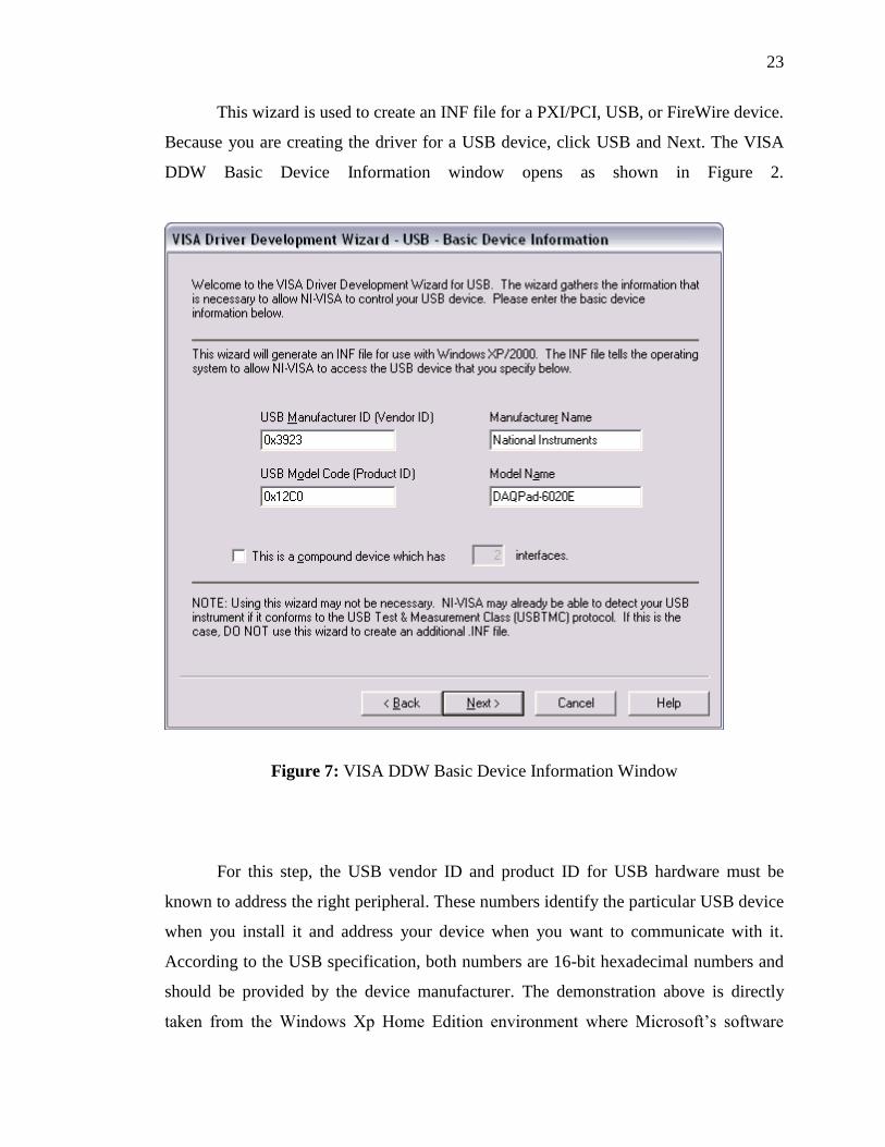
3.2.1.8 Autotronic’s Triggered MP4 Player
Figure 12: Overall Hardware (Red) Dell Desktop Computer (Blue) Advantech Data
Acquisition Card (Green) MP4 Player and Autotronics Control
This project used simple autotronics to short any of its 7 buttons of control on the
mp4 player. The circuit is shown below:

31
Figure 13: Darlington pair, impedance output and relays
Transistor were used because of different voltage of each circuit whereas relay
were use to negotiate with a straightforward and simple circuitry.
Digital outputs were used, for driving 6 relay of rated 6Vdc. Instead having
normal C9013 transistor, it was then replaced with a Darlington transistor C1209. Both
were NPN transistors but different in arrangement especially Darlington transistors have
the ability to share ground connection from the 5Vdc DAQ card with the autotronics
6Vdc circuit’s supply. It is specialized to handle data output interface such as Advantech
PCI-8710 had on it. IN14001 diodes were used to ensure compatibility and no back
flowing of current from either system one another.

32
3.2.2 Software
Block diagram programming using LabVIEW is also known as programming in
G. As reflect to nowadays culture of seeing things, programming in C to date is the most
popular one. C refers to computer programming while G refers to graphical
programming.
G programming popularity was increasing as most other software besides
LabVIEW is going to follow the same trends. Ladder diagram programming in
Programmable Logic Controls started to be the one of them, to have an easy yet
customizable programming. Today, PLC’s programming also use block diagram
programming instead of ladder diagram. It is the interest of who is the end user that
benefit from it.
This is due to professional such as engineers do not have a solid background in
programming specifically. Engineers do need however, to program as what they
application needs. NI introduces LabVIEW for this purpose. They do not need to know
into depth what machine language say, but they need to use it to get their jobs done. This
is actually derived from programmers view, where viewing into binary data transfer and
receive is also not a need. Let it be programming software to look into it. Up to the
demand that National Instrument take initiative to create graphical programming
environment where it was made to be intuitive and user friendly.
Next, to gain knowledge to program in G, there’s a need here to literate coding in
G, distinguish data type as it will become the right parameter feed, creating sub-VIs and
lastly to solve simple data acquisition tasks with LabVIEW with interfaced hardware
later on.
LabVIEW is a high level language that giving it's user a choice of functions
instead of typing it or referring to syntax programming guide. It is a norm for a

33
programmer to have the syntax programming book beside him when coding the
program. So the choice of having internally built functions is something similar with the
norm. With this kind of programming environment, many more advance feature played
by the functions can be fully utilized.
Some company is not that much concern on the details of the programming; they
intended programming tasks to be settled in order to fill their needs within a short period
of time. As for popularity, this specific type of programming is also entering the next
stage to become as popular as normal syntax typing programming language. Most of our
advance application in the near future will no longer need tedious job of typing, but
implementing instead block diagram to ask computer to help out for the tedious parts.
3.2.2.1 National Instrument LabVIEW version 8.2
The LabVIEW block diagram programming starts from left to right. Some of the
function consist its own already built program. It can later be customized base on the
needs of our program. For such needs, it is a very straightforward process. Putting
require process that refer to the program needs all inside the block, then interconnecting
it from left to right as well. The particular function must be connected to the similar
function type by the same group of wire. This includes session, image, error and data
lines. All else is connected when necessary and as an input or output to trigger
something else.
National Instrument has a very high reputation on developing this software
mostly used in instrumentation and measurement. Internationally, this type of
programming software is very highly recommended and the positive comment came
from its user and employee who put a requirement LabVIEW as compulsory on new
recruitment. Some company hires people just because they literate with LabVIEW
platform.

34
3.2.2.2 Measurement & Automation Explorer (MAX)
Figure 14: Measurement & Automation Explorer main graphical interface
Measurement & Automation Explorer (MAX) provides access to all your
National Instruments DAQ, GPIB, IMAQ, IVI, Motion, VISA, and VXI devices. With
MAX, you can configure your National Instruments hardware and software, add new
channels, interfaces, and virtual instruments, execute system diagnostics, and view the
devices and instruments connected to your system. MAX installs automatically with NI-
VISA version 2.5 or higher or NI-VXI version 3.0 or higher. MAX is available only for
Win32-based operating systems.

35
3.2.2.3 NI Vision Development Module
Figure 15: With NI Vision Development Module installed
It appears inside Vision and Motion sub Main Functions, where it has Vision
Utilities, Image Processing and Machine Vision. NI IMAQ for USB was taken from NI
IMAQ for USB device driver. NI IMAQ for USB will be explained later.

36
3.2.2.4 NI Vision Assistant
Figure 16: NI Vision Assistant
NI Vision Assistant gives a configurable image processing at user disposal, by
graphically see the changes each processing and compare it to original one. It is a newer
Vision Builder (explained later), processing in step-by-step and simple layout of pass
and fail step status screen. The parameters in this environment are then converted into
usable parameter to be fed in LabVIEW environment later on. This software is a trial
version, thus cannot be exported directly to LabVIEW. Redo all the function and some
findings through functions and library is necessary.

37
3.2.2.5 Vision Builder version 2.5
Figure 17: Shown Vision Builder Automated Inspection Version 2.5
There are two modes available within Vision Builder that is Configure Inspection
and Inspect Product. Configure Inspection were used to apply any functions and
processing to images setup for the particular project. On the other hand, Inspect Product
will use finished Vision Tasks to have evaluated the performance of any given system.

38
Figure 18: Inspection Mode to evaluate vision task or system performance
Vision builder is somewhat the same as NI Vision Assistant. It is an older
version of Vision Assistant and before it comes with a plug-in of vision assistant. For
today’s Vision Assistant are actually same as Vision Builder with some Vision Assistant
in complement with each other. Shown in figure 18 are the Battery Clamp Inspection
Demo were used to be inspected, where yield (%), Active vs. Idle Time data, parts per
second and Processing Time (ms).
3.2.2.6 NI IMAQ for USB Camera
The NI-IMAQ for USB Camera driver supports any camera with a Direct Show
filter. This typically includes any USB camera, microscope, scanner, etc, most IEEE-
1394 cameras, and even USB video adapters (takes analog video and converts it to
USB).

39
This driver is not meant for high-end vision applications because the cameras
that have Direct Show filters are typically consumer grade low resolution cameras. The
industrial IEEE-1394 cameras with Direct Show filters typically don't provide as many
resolutions and frame rates with the Direct Show filter as the IEEE-1394 interface
provides. This driver is geared towards academic applications and users who want to
acquire images but don't require high quality images. The camera's Direct Show filter
typically compresses images and adds compression artifacts to the image that make
image processing difficult.
The NI-IMAQ for USB Camera driver does not support grabbing from more than
one camera simultaneously. It is also recommended to use the driver with single
processor non hyper threaded machines. If you do have a dual processor or hyper
threaded machine, you can disable these features to allow for better USB acquisition
performance with this driver.
3.3 Preparation of Optimal Imaging
Images could be taken properly for vision application and further processing with
the consideration of imaging environment. This will greatly enhanced unneeded
processing in later stage.
3.3.1 Backlighting
The effect of backlighting discovered from the unsolicited condition of heavy
light from the background. The parameter of RGB used for color threshold were the
resultant of research onto how backlighting can assist computer not to get easily
confused.
40
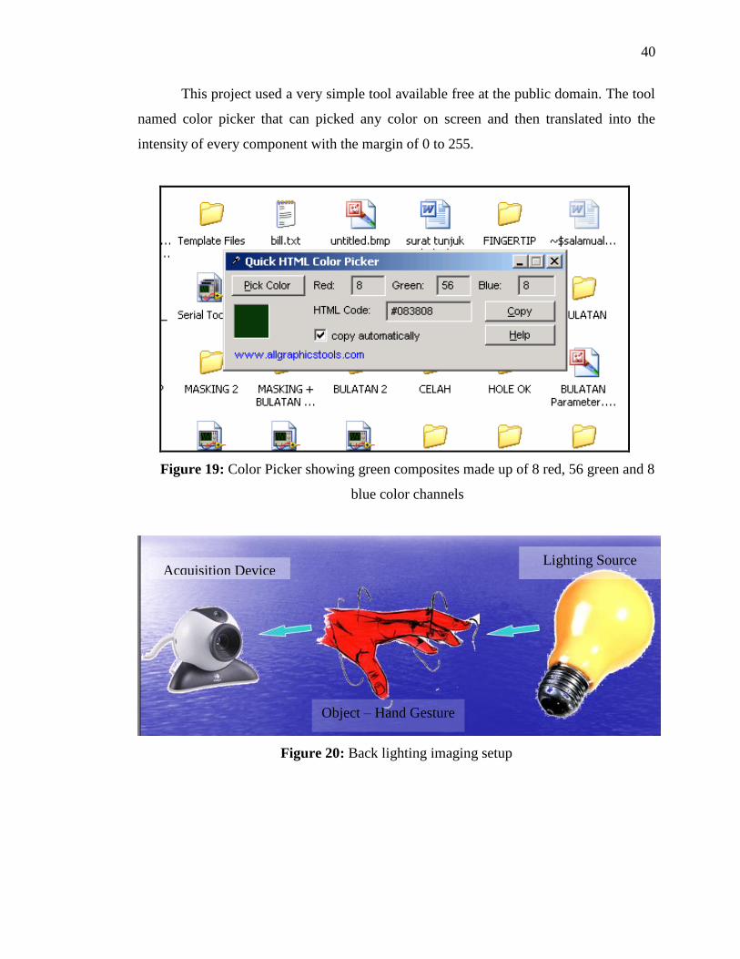
This project used a very simple tool available free at the public domain. The tool
named color picker that can picked any color on screen and then translated into the
intensity of every component with the margin of 0 to 255.
Figure 19: Color Picker showing green composites made up of 8 red, 56 green and 8
blue color channels
Figure 20: Back lighting imaging setup
Acquisition Device
Object – Hand Gesture
Lighting Source

41
Figure 21: Shown color image under backlighting effect
No. Red Green Blue
1 41 24 0
2
24 12 0
3 24 20 0
4 33 20 16
5 66 44 16
6 36 33 33
7 57 28 8
8 44 21 8
Table 1: Example of hand’s color composition samples

42
It is concluded that human skin contains dominant color of red, moderate number
of green and a small or no number of blue channels. The intensity of the color was
reduced to a smaller range. The table below is some of the values used for parameter
settings. This is important for having thresholding value from color thresholding
function. The best of this technique, the 32-bit RGB image will be changed to 2-bit
binary image at once processing only. This is the type of image that can be used to take
information out of it right away.
3.4 Process of Acquisition
Image Acquisition is actually referring to acquired by hardware available. Image
processing system uses any hardware capable of doing image snapshots and grab
continuous capturing ability. Acquisition in this context is the part responsible to acquire
in input to be processed later. This input then be manipulated, processed and changed
into useful information.
IMAQ is actually the abbreviation of Image Acquisition. Function that have
IMAQ is actually refers to certain parts that responsible for doing image information
capturing. The data stream of acquired images can be taken by discrete steps or
continuously. This can be illustrated by VI below:-
Figure 22: Acquisition using IMAQ USB Snap function

43
Snap function have the advantages over acquire to give sharper image and
require less time for a given input to be processed. This project incorporates this VI
instead of grab function. However, both can be used together for its own function.
Figure 23: Acquisition using IMAQ USB Grab Acquire function
A grab is a continuous, high-speed acquisition of data to a single buffer in host
memory. This function performs an acquisition that loops continually on one buffer [15].
Grab gives smoother images for displaying purposes.
The human’s hands movement is suitable for grab whereas snapshot taken to be
fed into system is suitable for snap. This is true as somewhat like our world such as
audio signal appears to be analog signal, but to be taken into system it must be spoon-
feed digitally.
Explained below are basic acquisitions in process whenever information from
web camera is taken into software part. Because LabVIEW access hardware without
anything and particular hardware resources needed to be freed, it is partly programming
to engaging it as well. Manufacturer fancy and easy software are non usable except what
the camera hardware side can do, that is snap and grab.

44
3.4.1 Initialize – engaging input hardware
Figure 24: IMAQ create
IMAQ create responsible for having an image container and create the specific
data to have a place in memory, name shown there as ‘image’. This name is important as
the memory is momentarily kept as a file.
Figure 25: IMAQ USB Grab Setup
Setup is required to have automatically connected USB web camera will all the
suitable settings. This are for doing the connection setup, thus if there are more feature
available from the hardware can be used if the programmer know really well the data
flow from the camera. The addressing has been explained earlier. Setup also determines
how data flows from the sensor to LabVIEW programs created.

45
3.4.2 Acquire
Figure 26: IMAQ USB Grab Setup
USB Grab Acquire will continuously acquire images in a very high rate at
approximately 25 ~ 26 frame per seconds. This project acquires 352x244 pixels of RGB
format images from Logitech QuickCam Express. Better response will not improve in
anyway the system performance. This project is very much software dependent.
3.4.3 Use data
Figure 27: Shown are images being used as an indicator and being
shown in front panel area

46
The information will be used for processing in background or being shown in
front panel. There are control for inputting programming variables and indicator for
displaying or give output to be seen in front panel.
3.4.4 Dump
Figure 28: To free the cache to be used for the next image to fill or done before
terminating application
After that, resources & cache used will be needed to be freed from the memory.
This will enable it being used again for any other purposes or for properly terminating
the whole program.
3.5 Preprocessing & Processing
This step was done to generate a clear image that is only the interest to be
processed out. This project was characterized into two main steps that is preprocessing
and processing. This project was to apply temporal, where all acquired images will be
processed. Thus there were neither minimizing the burden of preprocessing steps nor
mechanism skip processing steps of an issue.
To have a clear advantage of normal recognition, all acquired images will be
recognized, whether the user is performing a gesture or not. As a hypothesis, when

47
gestures are present and same as predefined, the scores of recognition is very good as
high as 800 over 1000. In contrast, when there is no gesture, the processed gesture will
leave no action state at all time. This is very tricky when it comes to a very bad
environment as computer mistakenly identified none of the predefined.
The performance, will not be elaborated here will be most likely almost the same
as the program will be going the same path over and over again. For more information
on performance, please refer to chapter 4.
LabVIEW keeps a library or group of function in block diagram area as
Functions. These functions can be used drag-and-drop to block diagram area. Image
processing functions is kept under Image Processing sub library.
(a) (b)
Figure 29: (a) Vision and Motion sub Library and (b) Image Processing sub library
48
The available have eight basic groups of functions. These processes are able to
automatically recognized inspection. The groups are as follows: -
i. Acquire Images
ii. Enhance Images
iii. Locate Features
iv. Measure Features
v. Check for Presence
vi. Identify Parts
vii. Communicate
viii. Additional Tools
The steps are a basic process for all image processing. By using image
processing, the capability is quite wide. Many other projects are being developed just to
copy what human vision can do. If most the development is a success, all the things that
human can do is no longer impossible to the robots and machine.
To have better understanding of the whole, this sub chapter 3.5 will be dedicated
to explain in great details of each of each processing function use within this project’s
scope.
3.5.1 Preprocessing
Preprocessing is the amendment process to filter out what is the region of interest
or area necessary to be take feature out of it. This step has nothing to do to improve
machine vision’s readability on specified system. It does however, to pin point the
location of hand, the object of interest of this project.

49
(a) (b)
Figure 30: Image Processing Steps (a) Image Acquisition, shown RGB type with
resolution of 352 x 244 pixels (b) Threshold
(a) (b)
Figure 31: Image Processing Steps (a) Remove small object (b) Lookup table
Image Processing Step Applied
1. Extract RGB – Red Plane 1
2. Threshold 1 – Auto threshold: Inter Variance
3. Remove Small Object – Iteration: 3, Square, Connectivity: 4/8
4. Lookup Table – Equalize
This is crucial to have an image usable for the next step. Next to have

50
(a) (b)
Figure 32: Image Processing Steps (a) Inverse Binary Image (b) Particle Filter
Image processing step applied
5. Inverse Binary Image
6. Particle Filter - % Area/Image Area, Keep: 10-100%, Conectivity: 4/8
By using particle filter, the image is very much ready to be processed. Resultant image
were very clear of anything besides biggest binary large object between 10 ~ 100% of
the whole area. The end result of this step determined how high the accuracy should be
as it goes to the next steps that is feature extraction processing.
Figure 33: Image Processing Steps: Find circle

51
Figure 34: The processing finds circular edge perfectly
crops at yellow line marking.
Figure 35: The automated masking and bottom y-coordinate for detaching arm with
surrounding particles (red) variables input (blue) new y-coordinate
The mid-point between two were taken by additional pixel to have it not to cut
too much. Thus, leaving some part of arm that is too small to sway output information.
Finding circular edge are for having average height of the centre of the hole to
cut a little bit at bottom of y position in order to discriminate arm area with the

52
surrounding that may have connection to arm. This step brings better accuracy of hand’s
area without most of the arm area. This step used to give a better approximation if the
center body mask used in find circle, feature extraction. Below are the same step
processed on a bigger sample of 640x480 pixels RGB image file. When bigger image
were used, the area is absolutely bigger, where the percentage will have very much the
same amount. This process successfully cropped y axis only its algorithm also shown in
figure 36.
Figure 36: This test image of 640x480 pixels is also compatible with the processing
3.5.2 Processing
Processing is to override the current image to an enhanced version. These steps
were done to optimize the system performance when feature extractions were made
upon. This involved process apply contrast or to filter out noise. Processing was also
made at processing level. Pre-processing and processing can happen between each other
and does not bounded with sequential operation. Both are used to complement each
other and at the same time both serve different function.

53
(a) (b)
Figure 37: Image Processing Steps (a) Threshold (b) Smoothing
Image processing step applied
7. Lookup Table – Equalize
8. Smoothing – Low Pass 1, Filter Size: 3x3
Smoothing will have an enhanced number of pixel deviations. Where the number
will most likely be lower and increase the chance of the step for feature extraction such
as Find Circular Edge to have pass state.
3.6 Feature Extraction
Programming has never been easier with graphical programming. Even with a
very easy way of coding, programming must be followed by a good practice to ensure
readability and neat program. Programming tends to contain error that needed to be
carefully corrected in order for it to work.
Pattern matching for fingertip have an output of position, angle, scale, score and
bounding box. All of this parameter has been under careful consideration and to have
score within acceptable margin. Trial and error first, then modification to perfected the
template and tweaking the parameter to give optimum score whether to fail or pass

54
inspected feature. Too easy on detection parameter will have many data to consider and
increase error on output state.
Most of the considerations were made under automated inspection within Vision
Assistant environment. Unfortunately, there were slight differences when comparing
data with the actual system completely under LabVIEW full programming. This might
occur because of differences in versions and refined function.
The parameter determined to be most unique are as follows:-
a. Circle
b. Wedge
c. Fingertip
d. Hole
3.6.1 Conversion Process
LabVIEW function gives output way different from Boolean logic format. The
data can be in cluster such as positions have the x-coordinate and y-coordinate each.
Each position is an array of positions of every object available.

55
3.6.2 Find Circular Edge
Figure 38: Outside deviation (arrow) Note the position of centre
The pixel deviates away too much because the finger was present.
Figure 39: Within deviation (arrow) Note the position of centre
The system is designed to have a dynamic variables so the system is more
automated than in the whole inspection vary depend on center body mass taken from

56
Particle Analysis data. This automated processed have been tested with different picture,
and different size apparently of 640x480 pixels.
Figure 40: Within deviation (arrow) note the position of centre
Find circular edges appear to be finding clear edges. By having gap decrease, the
roundness of object to evaluate also increases.
3.6.3 Pattern Matching – Fingertip Detection
All pattern matching regardless of what to match with, uses the same method in
order to carry out detection of feature. To have a match, feature to be found must being
compared to a template as. This thesis uses the word pre-defined as indication of average
look of what to find. This template must be selected from the most prominent image to
show important details of thumb or fingertip taken from the same hardware in this
system. For fine tuning, the picture selected was being trial and error method.
To understand how NI Vision Assistant do their observation. To have equally
good scores for most given acquisition, it must have normally with score greater than
800. The template can be selected randomly from any picture inside vision assistant. All

57
templates are stored in PNG files of height and width very small to increase speed in
calculation and to produce 8-bit or binary image containers.
Figure 41: Fingertip Detection Row 1 (arrow) Feature Extraction Data Out
Most of hand gesture recognition systems since the year 1992, the first attempts
were made to recognize hand gestures from color video signals in real time [17] was
fingertip detection. It is proven to be the only feature that did not appear twice (in the
meaning of occurrences) in human hands. This project also uses fingertip as the main
feature to be detected thus can freely be regarded as fingertip detection. This matter is
carefully being raised as the needs to detect fingertip remain the decision factor and can
affect the decision making process. Whereas other feature such as wedge, hole and circle
will affect only certain predefined gesture and if it does appear in any other gesture, the
decision of having it present be neglected if not necessary.

58
Figure 42: Thumb recognized as fingertip
Early development of this system, fingertip and thumb are separated as for human bare
eye, it has distinct differences. As compared to the picture below:-
Figure 43: Fingertip used as master template
The feature must appear to be unique. No connection should appear (referring to
black area in figure 42 and figure 43) to surrounding. The black area is actually holds 0
value of pixel location.

59
3.6.4 Pattern Matching - Others
Figure 44: Three fingertips were detected
Three fingertips were detected for having score over 800. As shown are 975
points matched, 984 points match and lastly 992 points. These template matched is said
to be almost as identical as predefined template.
Figure 45: Three fingertips and a circle were detected with score, angle and location
As shown feature output with all the information taken out from a specific
template detected. Among the criteria to be met so that the output would be true is the
orientation. Shown in figure 46 the origin of NI LabVIEW system is not as usually used
in daily life. Need to be pinpoint here this is machine translation. It is the default (0, 0)
origin coordinates for any image files. That is actually not a problem as machine states

60
the top and left as the origin and the other two as bottom and right as the maximum
width and height. This refers to maximum resolution of acquired signal.
Figure 46: Shown coordinate system and FT3 and FT4 criteria
FT3 will show hold true logic if the template is within deviation between the
angle of 5o to 25o and FT4 will hold true logic for any template detected within the angle
of 75o to 95o. Data was taken from and being evaluated under decision making section.
This is why there is a close relation of feature extraction section with decision making
module.
FT4
FT3

61
Figure 47: Two wedges detected with template shown
Figure 48: A hole detected with template shown
3.7 Decision Making
This project implements fuzzy logic in decision making module, where all data analyze
will be fuzzy logically output certain decision.
The decision is simple, that are:
1. no action
2. on / off
3. play
4. pause

62
5. fast forward
6. fast backward
7. volume up
8. volume down
Figure 49: Front Panel of the system including decided action
The decision have eight considerations, to put in binary system is 3 bit consideration.
Since this project is all about developing a recognition system, it will be classified into
four main group to fraction it down for easier fuzzy logic coding. This is in respect to
three group of two, which have identical gestures.

63
The first two bit will classify what group of two it will be. These four groups are as
follows:
1. Boolean of 00x for no action / stop gestures
2. Boolean of 01x for pause or resume / fast backward gesture
or
3. Boolean of 10x for volume up / volume down gesture
or

64
4. Boolean of 11x for play / fast forward gestures
or
All four groups will don’t-care the third bit values. When these four classifications
succeeded, this system will have 12.5 % accuracy. This action is also known as Data
Clustering.
Fine tuning recognition only needed for these two gestures.
or
Figure 50: 01x for pause or resume / fast backward gesture
There is not much different except the absent of thumb. Both have slightly
referring to the same gesture, but there is differences needed for the system to detect.
This includes what object, other information that can be incorporated with such as
position and bounding box. These features will help to decide is it appearing to be one
on the other. In another example below:

65
or
Figure 51: 10x for volume up / volume down gesture
The different is also not much except the orientation the object. Deep into
recognition matters, the most machine vision task can be fulfilled is by presetting
reference image and pattern matching.
From all, generally no arm is being taken into consideration. It is also wise to
build a system that determined by web camera at a base of a table and user input
gestures by laying his/her hands on the sensor’s equipped table. This is possible with
assist of external lighting and wide lenses. It is not used considering the hands location
can be anywhere inside a car. Fixed position will not make gesture input as an easier
choice. The purpose for easing will not be reached.
This simple making of the definition will easier guide programmer to go deeper
with advance fuzzy logic programming. To go briefly into fuzzy logic, the rule if x and
then y then z is used as a general rule. Only one criterion to be met, all definition is
represented in numerical values.

66
Figure 52: C1 and H1 logic from Decision Making for Circle and Hole respectively
Figure 53: Overall Decision Making to the output cluster of LCD

67
Figure 54: Modified parameter of x and y coordinate for find circular edge
Figure 55: Re-injecting new x and y position for find circle

68
Figure 56: Position, score, bounding box, angle and scale
Figure 57: Improved Decision Making front panel
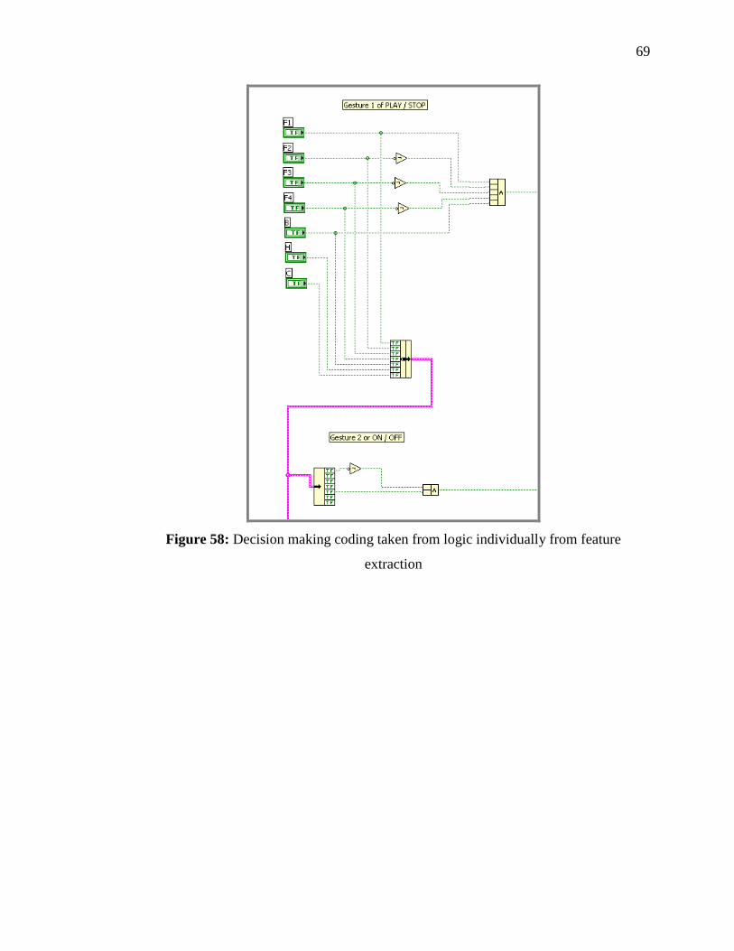
69
Figure 58: Decision making coding taken from logic individually from feature
extraction

70
CHAPTER 4
RESULTS & DISCUSSION
4.1 Introduction
Performance of any recognition system is by the degree of precision of any given
signal fed into it and recognized. This system emphasis more on fingertip recognition as
the main feature to be evaluated thus requires a comparison to available system using the
very same method as well. This also include how fast the system can compute to churn
out last bit parameter completely to Boolean logic then to decide what to do.
Precision for this system is very subjective. This system is made very loose in
evaluating correct parameter output. To detect many blobs, it is held on algorithm to
filter out only the highest probability of gesture and the quality of acquisition is it can or
not take it up into decision process. Fingertip system available outside can have the very
good result up to 90 over percent.
71
4.1.1 System Performance
This system was evaluated by having the calculation to a very big sample size of
any picture, regardless of output it made. The system capable of doing 450 ~ 500 ms or
approximately 2 frame per second. The speed calculation was also being made under
Vision Assistant Environment. The actual calculation time vary between images
acquainted. Some processing takes more time than the other, and this also apply to
images information type and size. This project feeds on JPG files, a compressed version
of BMP files and RGB color set.
This project is considered successfully if only both of decision making can
decide out from the acquisition, processing and anything else are working together
wonderfully. Beside that, the key performance indicator for this project lay on the
percentage of successfulness to translate gesture given into command with minimal
acceptable error margin. The gestures include no matter what size, background, noise or
lighting condition, the system still work together. To have this done is the most
challenging part of all.
4.2 Discussion
This project must have an output no matter what. The last improved decision
making VI was tested by running continuously and proven to be giving only one input at
any given time. At the gesture not detected, the algorithm found none and the scores are
low, no action will active. Other than that, only one will active above 7 possibilities.

72
Table 2: Feature Extraction Summary
No Description Gesture
1 Play / Pause
2 ON / OFF
3 Mode
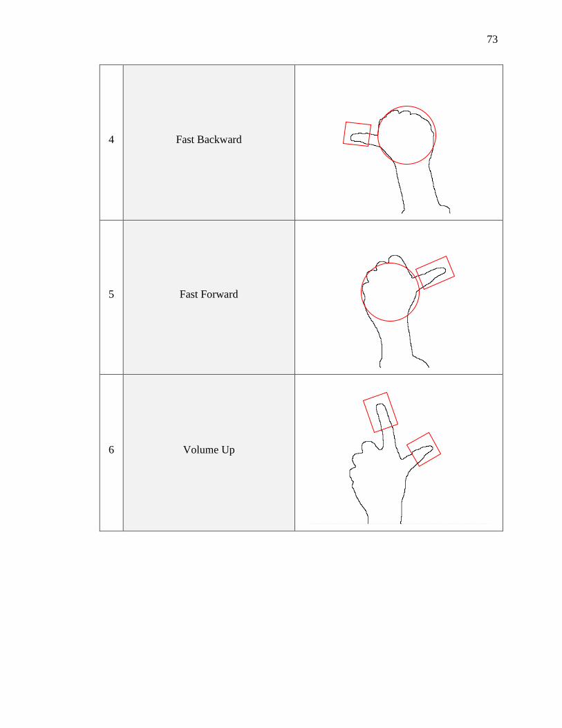
73
4 Fast Backward
5 Fast Forward
6 Volume Up

74
7 Volume Down
Shown is the finalized decision making Boolean rule to follow. Notes there are too many
don’t care everywhere. This give the system flexibility upon evaluating any hand gesture
fed into it.
Table 3: Decision making truth table
Boolean \ Gesture 1 2 3 4 5 6 7
FT1 T F T T T T T
FT 2 F X T F F F F
FT 3 F X F F T X F
FT4 F X F T F F X
C1 T T X T T F F
H1 X X T X X X X
W1 X X T X X X X
Remarks
FT: Fingertip
C: Circle
H: Hole
W: Wedge

75
Any result other than on the truth table will return to no action. As seen in the
above table, result is very much depends on how much feature detected within the
system. This project at evaluation phase has a cumulative of 246 samples each represent
varieties of gesture. There are only 7 gestures whereas the eighth is going to be the only
decision when the detection didn’t return any results. Among the 246 samples, for
astounding 175 were rejected as having to heavy background, giving for only 71
samples to be used. All samples are included in the DVD attached at the back.
4.2.1 System Limitation
Table 4: Result for feature recognition
No Feature Results Comment
1 FT1 65/71
Problems at gesture number three, attaching
particle regarded as detached features
especially at low score as predefined
settings.
2 FT2 65/71
3 FT3 65/71
4 FT4 64/71
5 C1 59/71 Return very tricky, need some advance
detection
6 H1 63/71
7 W1 57/71 Worse when unwanted background
available.

76
As refer to earlier discussion, this feature will be evaluated functional and
effective (denoted as how many per the sample size) if it turns true when feature
available and turn to false when feature unavailable.
Wedge turn to be the worse as almost anything can give illustrate wedge shape in
particular. The predefined matching is very lenient as the location can be almost
anywhere. There are gesture than cannot filter out all the background noise and left out
only the gestures, that is where wedge detected too much as the background became
them.
Most of the acquisition for bigger sensor sized image return zero. These parts
still needed to be refined in the future. Fingertip is very effective. It turns to be if the
FT1 is okay, the FT2, FT3 and FT4 will be okay as well. The only different is at the
orientation and how many were detected. The only problems occur when attaching
particles are declared as fingertip as well.
Table 5: Result for gesture recognition (Please refer table 2 for gesture number)
No Gesture Results Comment
1 1 34/71
2 2 37/71
3 3 24/71
4 4 27/71
5 5 34/71
6 6 0/71 Decision making problems
7 7 0/71 Decision making problems
This result is much easier as it can be observed by the front panel. This project
comes with a live acquisition version, however is it not comfortable to take
measurement when it is in live mode as this system return output very much faster than
taking measurement. The outcome is very positive despite limitation under certain
lighting condition and for having almost blank as background. This part of evaluation

77
will evaluate functional and effectiveness (denoted as how many per the sample size) if
it turns true when gesture match what have been given and turn to false when gesture
unavailable. The numbers a quite low, but by looking at the earlier table of feature
extraction, detecting more feature and improved decision making programming rules is a
good idea.

78
CHAPTER 5
CONCLUSION
5.1 Conclusion
It is concluded that this project have successfully achieved its objective by
having a complete system of recognition and be able to deliver output to respective
device. However, there are plenty of rooms of improvement especially in processing and
training for this purpose. The system can be developed to do additional processing
where needed or to bypass unnecessary processing. This can be accomplished by using
artificial intelligent programming. The numbers of sample should be improved in the
future. This problems lies at sample collection that turns out saving picture on the same
file over and over again. At last, the only solution is to acquire input images manually.
Interfacing between software and hardware should address the usability of widely
accepted standards such as serial and parallel communication or even a USB port.

79
5.2 Future Recommendation
It is hopefully this project could reach end with a success of a minimum error working
system. This project is hopefully being used for the following:
i. To be used as a basis of motion processing. These include conveying information
with not only capture function but also grab function, available in LabVIEW.
ii. To be later assist the advancement and courses on advance usage of LabVIEW
programming environment especially attached with Instrumentation &
Measurement subject. The subject is available in electrical, mechanical, civil and
chemical engineering
iii. To be used coupled with technology such as holographic technology.
iv. To be used as a video editing software that use motion input to control the
editing process and fixed to timeline functions.
It’s a very good start for having advance usage of image and motion processing and
analysis in the future.
5.2.1 Cost & Commercialization
The cost impact for a recognition system can start for as low as RM 130 to a few
thousand ringgit. As reflected for this project the cost is very low. This includes
assumption of the interested party have a personal computer and LabVIEW software
installed and running at their disposal.
For a web camera will only cost not more than RM75 per unit. For the
autotronics parts, the pricing for simple circuitry hardly exceed RM50. The cost of
overall system will be much if higher performance devices were used such as IEEE-
1394 cameras or Line Scan conveyor belt camera. These cameras were design to cut
processing time by having some optimum imaging function built from the hardware

80
section. In some design, high performance camera is more cost effective, as the general
rules are all varied.
In industrial application, very fast camera not just the only option when
encountering abundant pending vision tasks. Using multiple camera arrangement can
also achieve the same results to complement with the software part. IEEE-1394 for
example has the capability to be used in multiple acquisition arrangement. The
performance of the camera is also good. The cost for a firewire cameras vary from
RM300 to RM500 based on its functionality. By having setting up multiple cameras
with firewire devices, a multiplexer will be added to complete the system.
Table 6: Cost impact
No Item Per Unit (in MYR) Qty
Sub total
(in MYR)
1 LabVIEW Base System for
Windows with 1 Yr
Service (English)
4 748 1 4 748
2 NI Vision Development
Module Ver 8.5, Includes 1
Year SSP
13 064 1 13 064
3 NI Vision Run-Time
License 1 184 1 1 184
4 Autotronics control circuit 67 1 67
5 Web camera 75 1 75
6 Advantech DAQ Card 3 000 1 3 000
TOTAL 22 138
As for looking of limitless capability, it is a viable investment to be made. If
there is enough time, more time can be used to enhance the capability of the whole

81
system. The purpose of this sub chapter is to support informed decision before selecting
to spend on any particular software for development purposes.

82
REFERENCE
[1] Museum of Vision Science, School of Optometry, University of Waterloo. (2007)
“Fact about Eyes” http://www.optometry.uwaterloo.ca/~museum/answer2.htm
[2] MIRA GETV (2006), “Modern Marvel, Car Tech of the Future” Video www.the-
realworld.de
[3] Wikipedia (2006). Article “Definition of Human Interface Device”
http://en.wikipedia.org/wiki/Human_interface_device
[4] Oxford University Press (2006). Concise Oxford Dictionary (Tenth Edition).
“Meaning of gesture” http://www.askoxford.com/?view=uk
[5] Wikipedia (2006). Article “Definition of Image Processing”
http://en.wikipedia.org/wiki/Image_processing
[6] National Instrument Corporation (2005). “NI Vision Concept Manual”.
Austin, Texas: Worldwide technical support and Product Information
[7] Wikipedia (2006). Article “Definition of Pixel” http://en.wikipedia.org/wiki/Pixel
[8] Wikipedia (2006). Article “History of Digital Image Processing”
http://en.wikipedia.org/wiki/Digital_image_processing#History
[9] Ibid
[10] Wikipedia (2006). Article “Definition of Digital Image Processing”
http://en.wikipedia.org/wiki/Digital_image_processing
[11] National Instrument Corporation (2001). “LabVIEW Machine Vision and Image
Processing Course Manual”. Austin, Texas: Worldwide technical support and
Product Information
[12] Ibid
[13] Ibid
[14] Jeremy Kennedy (2005). Logitech G15 Forums. “The Logitech G15 FAQ”
http://www.g15forums.com/
[15] Prof. Paul Y. Oh (2001). “TRIPOD, Template for Real-Time Image PrOcessing
Development” Drexel University in Philadelphia,
http://www.boondog.com/tutorials/tripodBinarize/tripodBinarize.html

83
[16] The American Heritage® Dictionary of the English Language, Fourth Edition
(2000). “Definition of Vision” Houghton Mifflin Company.
www.thefreedictionary.com/vision
[17] Markus Kohler, Sven Schröter &Helge Baier (2001). “Vision Based Hand Gesture
Recognition Systems” Computer Graphics, University of Dortmund, http://ls7-
www.cs.uni-dortmund.de/research/gesture/vbgr-table.html

84
Appendix A

85

86
Appendix B

87
Appendix A
Appendix B