universidad politÉcnica de madridoa.upm.es/51150/1/tfm_aleksandar_zivkovic.pdf · 2018. 6. 4. ·...
TRANSCRIPT

UNIVERSIDAD POLITÉCNICA DE MADRID
ESCUELA TÉCNICA SUPERIOR DE INGENIEROS INFORMÁTICOS
MÁSTER UNIVERSITARIO EN INGENIERÍA DEL SOFTWARE – EUROPEAN MASTER IN SOFTWARE ENGINEERING
Development of Autonomous Driving using Robot Operating System
Master Thesis
Aleksandar Živković
Madrid, May 2018
This thesis is submitted to the ETSI Informáticos at Universidad Politécnica de Madrid in partial fulfillment of the requirements for the degree of Master of Science in Software Engineering.
Master Thesis Master Universitario en Ingeniería del Software – European Master in Software Engineering Thesis Title: Master Development of Autonomous Driving using Robot Operating System Thesis no: EMSE-2018-3 May 2018
Author: Aleksandar Živković BSc University of Oulu
Supervisor: Co-supervisor:
Pasi Kuvaja Professor, PhD University of Oulu
Name Surname1 Surname2 Academic title University of the presented title
Faculty of Information Technology and Electrical Engineering University of Oulu
Department School University
ETSI Informáticos Universidad Politécnica de Madrid Campus de Montegancedo, s/n 28660 Boadilla del Monte (Madrid) Spain
Development of Autonomous Driving using ROS
University of Oulu
Faculty of Information Technology and
Electrical Engineering / M3S
Master’s Thesis
Aleksandar Živković
1.6.2018.

2
Abstract
Autonomous driving, or self-driving, is the ability of a vehicle to drive itself without
human input. To achieve this, the vehicle uses mechanical and electronic parts, sensors,
actuators and an on-board computer. The on-board computer runs sophisticated
software which allows the vehicle to perceive and understand its environment based on
sensor input, localise itself in that environment and plan the optimal route from point A
to point B. Autonomous driving is no longer a thing of the future, and to develop
autonomous driving solutions is a highly valuable skill in today’s software engineering
field.
Robot Operating System (ROS) is a meta-operating system that simplifies the process
of robotics programming. This master’s thesis aims to demonstrate how ROS could be
used to develop autonomous driving software by analysing autonomous driving
problems, examining existing solutions and developing a prototype vehicle using ROS.
This thesis provides an overview of autonomous driving and usage of ROS in the
development of autonomous driving, then elaborates on the benefits and challenges of
using ROS for autonomous car development.
The research methods used in this master’s thesis are design science research (DSR) and
a literature review. An artefact is developed and evaluated—a remote-controlled (RC)
car equipped with Raspberry Pi 3 board as the on-board computer, an Arduino Uno
board, Teensy LC board, a set of sensors and ROS-based software. The thesis is
supported by the author’s employer, automotive software company called Elektrobit.
By following the steps described in this thesis, it is possible to develop an autonomous
driving RC car which runs on ROS. Additionally, this thesis shows why ROS provides
good solutions for the autonomous driving issues. It points to the benefits of ROS: open
sourced, peer-to-peer, network-based meta-operating system with ready-made
components for autonomous driving, and highlights some of the challenges of ROS:
security issues and single point of failure.
Keywords Autonomous Driving, Self-driving, Robot Operating System, ROS, RC Car
Supervisor Professor Pasi Kuvaja, University of Oulu
Co-Supervisor Professor Ricardo Imbert Paredes, Universidad Politécnica de Madrid

3
Foreword
I would like to express my sincere gratitude to my employer, Elektrobit Oulu, for
allowing and encouraging me to work on my master’s thesis, ‘Development of
Autonomous Driving using ROS’. I extend my deepest thanks to all my colleagues from
Elektrobit and all who contributed directly or indirectly to my thesis, especially to
Erling Stage.
I would also like to thank my supervisors, Professor Pasi Kuvaja and Professor Ricardo
Imbert Paredes, for providing me with guidance, feedback and support throughout the
entire thesis process.
This thesis and my master’s studies were supported by the European Master in Software
Engineering (EMSE) programme, to which I owe a debt of sincere gratitude.
Finally, without the support of my family, this work would have been much more
difficult, thus my thanks go to my family as well.
Aleksandar Živković
Oulu, June 1, 2018

4
Abbreviations
ROS Robot Operating System
SW Software
HW Hardware
IMU Inertial Measurement Unit
EB Elektrobit
DSR Design Science Research
RC Remote Controlled
SLAM Simultaneous Localisation and Mapping
SSH Secure Shell

5
Contents
Abstract ............................................................................................................................. 2 Foreword ........................................................................................................................... 3 Abbreviations .................................................................................................................... 4 Contents ............................................................................................................................ 5 1. Introduction .................................................................................................................. 6 2. Research Problem and Methodology ........................................................................... 8 3. Prior Research and Background ................................................................................. 12
3.1 Autonomous driving .......................................................................................... 12 3.1.1 The concept of autonomous driving ....................................................... 12 3.1.2 Vehicle autonomy levels ........................................................................ 13 3.1.3 Sensors of self-driving vehicles .............................................................. 14 3.1.4 SW block diagram of self-driving vehicles ............................................ 15
3.2 Robot Operating System (ROS) ........................................................................ 16 3.2.1 ROS Overview ........................................................................................ 17 3.2.2 ROS nodes .............................................................................................. 18 3.2.3 ROS messages ........................................................................................ 19 3.2.4 ROS topics .............................................................................................. 19 3.2.5 ROS services .......................................................................................... 19
3.3 Usage of ROS in autonomous driving development ......................................... 20 3.3.1 ADAS Development Vehicle Kit ........................................................... 21 3.3.2 Stanford Racing’s Junior ........................................................................ 21 3.3.3 AutoRally Project ................................................................................... 21
3.4 Requirements derived from the literature .......................................................... 22 4. Design ......................................................................................................................... 23
4.1 Developing the requirements ............................................................................. 23 4.1.1 Company requirements ........................................................................... 23 4.1.2 Final requirements .................................................................................. 24
4.3 EB Hobby Car .................................................................................................... 26 4.4 Designing the system structure .......................................................................... 29 4.5 Development ...................................................................................................... 30
4.5.1 ROS on EB Hobby Car ........................................................................... 31 4.5.2 ROS Development .................................................................................. 31
5. Evaluation ................................................................................................................... 42 6. Discussion .................................................................................................................. 45 7. Conclusion .................................................................................................................. 47 References ....................................................................................................................... 48

6
1. Introduction
We live in an era of rapid technological improvement, what with the advance of
artificial intelligence, sensors, communication technologies, software (SW) and
hardware (HW) engineering and other industries—not least of which is the automotive
industry. In this new age, smart, autonomously driving cars are no longer ideas of the
future—they are things of the present. As automotive tycoons and powerful software
companies try to get ahead in the self-driving business, engineers who can work with
the technologies needed for developing autonomous cars are of high value.
Robot Operating System (ROS) is one such technology that can be used to develop
autonomous cars (Tellez, 2017). Robot Operating System is a meta-operating system,
which contains a set of tools and libraries that aim to make robotics programming more
comprehensive (Reddivari et al., 2014). Additionally, to achieve that goal, ROS
enforces certain robotic programming conventions (Reddivari et al., 2014). We can
think of autonomous cars as robots because, in fact, that is what they are: robots with
sensors (GPS, odometers, ultrasound sensors) and actuators (wheels, servos, motors).
Davies (2017) projects that the era of measuring a car’s power by that of its engine is
about to end. In the coming era, the autonomous driving era, car power will be
measured by the power of the vehicle’s sensors, computers and SW (Davies, 2017).
Despite advancements, however, programming of robots is still very difficult. One
reason for this is that robots can work in different HW environments and run on various
SW systems. Code reusability is a big issue, as SW is often highly coupled and built for
specific HW. Even if one identifies a piece of relevant code from someone else’s work,
reusing code written specifically for another platform poses a challenge. As a flexible
meta-operating system for writing robotic SW, ROS offers an opportunity to overcome
these issues (Quigley et al., 2009).
The objective of this master’s thesis is to analyse how ROS can be used to develop and
run autonomous driving SW and to identify the benefits and challenges of using ROS to
develop autonomous cars. An employee of the automotive SW company Elektrobit
(EB), the author of this paper was motivated to conduct this research by EB’s interest in
autonomous driving, particularly that using ROS. The topic in general is an attractive
one, as common interest in autonomous driving is rapidly increasing. Solutions for
autonomous driving problems, especially those that use open-source SW such as ROS,
could be very useful to the autonomous driving community.
The main aim of this research is to provide insight into how ROS can be used to
develop autonomous driving and to identify its benefits and challenges. Both scientific
circles and the automotive SW industry can benefit from the results of this investigation
as it will analyse both the design and implementation of autonomous cars using ROS.
The present review examines the existing literature related to autonomous cars, ROS
and the use of ROS in autonomous cars. This literature review is then used as the basis
for the main research of the thesis, which uses the design science research (DSR)
method. This includes developing an artefact using DSR—in this case, an autonomous
7
remote-controlled (RC) car, called ‘EB Hobby Car’, running on ROS, specifically ROS
Kinetic. Development of the artefact is done in iterations following DSR guidelines.
This thesis strictly follows the template and instructions given by Halonen (2015) from
the University of Oulu. This template guides students to write a proper master’s thesis
per the regulations of the University of Oulu (Halonen, 2016). This paper begins by
defining the research problem and research questions, then explains in detail the chosen
research methodology—DSR. A literature review is performed to gather knowledge
about the prior research on the present topic. The results of this literature review are
then used to introduce the topics of autonomous driving, ROS and the use of ROS to
develop autonomous cars. The literature review’s results also inform the initial set of
requirements formed in the present study. This set of requirements, named ‘literature
requirements’, serves as a base for the following DSR. The core part of the thesis is the
in-depth description of the performed DSR, followed by an evaluation of the results of
the DSR against the previously established requirements. Finally, the results of the
thesis are presented, the research questions answered, limitations of the study pointed
out and ideas for future work proposed. A summary of the main findings concludes the
paper.

8
2. Research Problem and Methodology
An informal literature review was conducted to gather prior knowledge related to the
research topic. The review focused on literature containing information about
autonomous driving, ROS and use of ROS in developing autonomous cars. The main
research method was DSR. As there was no need for a systematic or structured literature
review, the literature was collected, read and analysed in an ad hoc manner. Due to the
novelty of the topic, non-scientific literature, such as blog posts and websites, was also
reviewed. ROS use in autonomous driving development is a relatively new topic, so the
volume of peer-reviewed literature on the subject was limited; this justified the
inclusion of non-peer–reviewed literature in the review.
After gaining knowledge about the research topics from the literature, related projects in
which ROS was used for the development of autonomous cars were selected and
analysed. The core of this thesis is the conducted DSR, which is described in detail
below. The main research problem was to analyse how ROS can be used in the
development of self-driving vehicles and to identify its potential benefits and
challenges. To solve the research problem, the following research questions were
proposed:
RQ1: How can ROS be used in the development of autonomous driving?
RQ2: What are the benefits and challenges of using ROS in the development of
autonomous driving?
The first research question was answered by describing the steps needed to create the
present experiment’s autonomously driving RC car using ROS. By answering the first
question and analysing the related literature, the benefits and challenges of using ROS
for autonomous driving were identified, thus answering the second research question.
With the research questions answered, the initial research problem could be addressed.
As noted above, the literature review served to provide insight into the field of
autonomous driving, learn about ROS and understand how ROS can be used to develop
self-driving vehicles. No systematic literature review was conducted, as the use of DSR
negated the need for rigorous literature analysis. Google Scholar and Science Direct
databases were searched for the relevant scientific literature. When there was no
scientific literature available, Wikipedia and popular ROS websites and blogs were used
to search for related non-scientific literature.
In the conducted DSR, the results of the literature review were used to build the
knowledge base upon which the artefact could be constructed. Thus, the main output of
the performed literature review was the compiled set of requirements, called ‘literature
requirements’. This set of requirements was used as a basis for the DSR that followed
the analysis. Building on these requirements, additional requirements were compiled
through conversations with experienced professionals from EB. The final set of
requirements was created by merging the literature and company requirements. Once
the final set of requirements was in place, the design part of the DSR began.

9
The formal definition of DSR, given by Hevner and Chatterjee (2010), is as follows:
“Design science research is a research paradigm in which a designer
answers questions relevant to human problems via the creation of innovative
artefacts, thereby contributing new knowledge to the body of scientific
evidence. The designed artefacts are both useful and fundamental in
understanding that problem (Hevner & Chatterjee, 2010, p. 5).”
Due to the empirical nature of the present research, wherein a new system is constructed
and evaluated, the DSR methodology was a realistic research method. DSR is a research
methodology in which the design problem is understood and solved by building and
applying a viable artefact (Hevner, March, Park, & Ram, 2004). The artefact can be a
construct, a model, a method or an instantiation, which helps to explain and address
information system-related problems (Hevner, March, Park, & Ram, 2004). The artefact
is developed in iterations and then evaluated to produce the wanted outcome. In this
thesis, an autonomous, ROS-running RC car and the developed autonomous driving SW
qualify as the artefacts of this DSR.
There are several different DSR-related frameworks. These generally differ in their
views on what should be emphasised in the research process and how research should
be conducted in general. In this thesis, framework presented by Hevner (2007), as
shown in Figure 1, is adopted in an applied manner, because it fit well the purpose and
the environment of this DSR.
Figure 1. Design science research cycles (Hevner A. R., A Three Cycle View of Design, 2007).
Hevner’s (2007) DSR cycles were followed to answer the research questions. As stated
by Hevner and Chatterjee (2010), the cycles of DSR are:
Relevance cycle. Works as a bridge between the research environment and DSR
activities.
Rigor cycle. Works as a bridge between DSR activities and the knowledge base of
scientific theories and methods, existing expertise and gained experience.
Design cycle. Iterated by repeating the core activities of building and evaluating the
design artefacts and processes within the research.
10
The main goal of DSR is to improve the environment throughout the whole process of
the artefact building and by the built artefact itself. In DSR, a research problem is is
solved by designing, implementing and studying of an artefact in an iterative way
(Hevner & Chatterjee, 2010). DSR starts by identifying the problems and the
opportunities of the environment, by identification of the context of the application
(Hevner & Chatterjee, 2010). This context is what provides both the design
requirements and the acceptance criteria for the evaluation of the developed artefact and
the research itself (Hevner & Chatterjee, 2010). The results of the evaluation reveal
potential issues in functionality or performance and inform the decision as to whether
additional iterations of the relevance cycle are required (Hevner & Chatterjee, 2010).
The knowledge base of theories and methods provide the foundation for rigorous
research in DSR (Hevner & Chatterjee, 2010). The knowledge base is composed out of
the prior research, existing artefacts, experiences and expertise (Hevner & Chatterjee,
2010). The rigor cycle builds on prior research by adding new artefacts and experiences
gained from the research work and its evaluations in the application environment to the
existing knowledge base (Hevner & Chatterjee, 2010).
During the design cycle, artefact is built in an iterative manner, whereas after each
iteration, the artefact is evaluated and potential refinement feedback is given (Hevner &
Chatterjee, 2010). Design cycle activities, construction and evaluation, are basically
being repeated until the constructed artefact does not fulfil the requirements set prior
(Hevner & Chatterjee, 2010). Both the construction and evaluation must be performed
with rigor and purpose (Hevner & Chatterjee, 2010).
The immediate environment of the research was EB’s office in Oulu, where the created
artefact was to operate. The wider environment included current practices of automated
driving, automotive SW development and SW engineering approaches. The information
about ROS and similar projects were gathered from analyses of the literature and related
projects. The information was used to create the present research’s knowledge base.
This knowledge was used to write the present thesis’ introduction, and to compile the
initial set of requirements needed for development of the artefact. From the DSR
perspective, the literature requirements contributed applicable knowledge to build the
artefact. As the core part of this research was the development of the artefact, the
development was done in several cycles to achieve the complete system. Each cycle had
its own objectives to accomplish. The main cycles of this DSR are described below.
Cycle 1: Developing the requirements. The objective here was to develop a list of
requirements for the system. The final list merged requirements extracted from the
literature and those noted in the discussion with experienced company professionals.
Cycle completion was evaluated by analysing the validity of the final requirements with
the company professionals, with consideration for budget and other limitations.
Cycle 2: Designing the system structure. The objective of this cycle was to design the
structure of the system’s components. The structure was based on the requirements
developed in the previous cycle. The completion of the cycle was evaluated by
confirming that the structure met the requirements and the objectives of the thesis.
Cycle 3: Developing and testing the system. The objective of this cycle was to use the
system to perform its features according to the developed system structure. The
components chosen in the previous cycles were used. The completion of the cycle was
evaluated by confirming that the system could perform the desired features
satisfactorily.

11
After the cycles were completed, the entire system was evaluated. This was done by
analysing its performance and capabilities according to the requirements set prior. The
results of the literature review and reflections on the DSR process allowed the research
questions to be answered, thus solving the initial research problem. With the research
questions answered and the research problem solved, the knowledge gained from this
research may contribute significantly to the knowledge base.
12
3. Prior Research and Background
In this chapter, the analyses of prior research and related works are presented. These
analyses introduce the concepts of autonomous driving, ROS and the use of ROS in
autonomous driving development.
3.1 Autonomous driving
The idea of automating vehicles is an old one. People have been trying to automate cars
and aircrafts since 1930, but the hype for self-driving cars skyrocketed between 2004
and 2013. To encourage autonomous car technology, the U.S. Department of Defense’s
research arm, the Defense Advanced Research Projects Agency (DARPA), created a
challenge called the Grand DARPA Challenge in 2004 (Joseph, 2017). The aim of the
challenge was to design a vehicle that could drive autonomously through real world
environment (Joseph, 2017). The winner of the challenge was Team Taran Racing from
Carnegie Mellon University, and the second placed team was Stanford Racing from
Stanford University (Joseph, 2017).
DARPA challenges popularized autonomous driving and pushed the automotive
companies to start working on implementation of the autonomous driving capabilities in
their vehicles (Joseph, 2017). Currently, almost all automotive companies are trying to
develop their own model of a self-driving car. In 2009, Google started to develop its
own self-driving car, now known as Waymo, which has greatly influenced other
companies to start autonomous car development on their own (Davies, 2017).
3.1.1 The concept of autonomous driving
A car capable of autonomous driving should be able to drive itself without any human
input (Autonomous car, n.d.). To achieve this, the autonomous car needs to sense its
environment, navigate and react without human interaction (Autonomous car, n.d.). A
wide range of sensors, such as LIDAR, RADAR, GPS, wheel odometry sensors and
cameras are used by self-driving cars to perceive their surroundings. In addition, the
autonomous car must have a control system that is able to understand the data received
from the sensors and make a difference between traffic signs, obstacles, pedestrian and
other expected and unexpected things on the road (Autonomous car, n.d.).
For a vehicle to operate autonomously several real-time systems must work tightly
together (Levinson et al., 2011). These real-time systems, as identified by Levinson et
al. (2011), include environment mapping and understanding, localisation, route planning
and movement control. For these real-time systems to have a platform to work on, the
self-driving car itself needs to be equipped with the appropriate sensors, computational
HW, networking and SW infrastructure (Levinson et al., 2011).
Autonomous driving has many benefits for humankind. Zakharenko (2016) predicts that
autonomous transport will reduce the cost of travel, allow children to travel without
present adults and relieve people from the burden of driving, all of which will result in
an enhanced travel experience. Zakharenko (2016) adds that the self-driving cars will be
safer, choose more optimal routes and increase highway throughput. Zakharenko (2016)
also adds that the cars will be able to park themselves, if needed, far away from their
13
owners, which would reduce the parking costs. Finally, Zakharenko (2016) notes that
the interest in autonomous driving developers is increasing together with the growth of
the autonomous driving industry. One of the valuable skills, that those autonomous
driving developers could have in their pockets, is the knowledge of ROS programming
(Zakharenko, 2016).
For a machine to be called a robot, it should satisfy at least three important capabilities:
to be able to sense, plan, and act (Joseph, 2017). For a car to be called an autonomous
car, it should satisfy the same requirements (Joseph, 2017). Self-driving cars are
essentially robot cars that can make decisions about how to get from point A to point B.
The passenger only needs to specify the destination, and the autonomous car should be
able to take him or her there safely. To transform an ordinary car into an autonomous
car requires the addition of sensors and an on-board computer (Joseph, 2017).
3.1.2 Vehicle autonomy levels
Joseph (2017) identifies six levels of vehicle autonomy:
Autonomy Level 0. Vehicles with level 0 autonomy are completely manual, with a
human driver. Most old cars belong in this category (Joseph, 2017).
Autonomy Level 1. Vehicles with level 1 autonomy have a human driver, but they also
have a driver assistance system that can automatically control either the motor or
steering systems using environmental information (Joseph, 2017).
Autonomy Level 2. This level qualifies as partial automation, as at this level, the
vehicle can perform both motor control and steering functions, while all other tasks are
controlled by the driver (Joseph, 2017).
Autonomy Level 3. This level is called conditional automation, as at this level, it is
expected that all tasks are performed by the car autonomously, though it is also
expected that a human will intervene whenever required (Joseph, 2017).
Autonomy Level 4. Joseph (2017) states that at this level, there is no need for a human
driver, as everything is handled by an automated system. This level is called high
automation and this kind of autonomous system will work in a set type of area under
specified weather conditions (Joseph, 2017).
Autonomy Level 5. This level of autonomy is called full automation, as at this level,
everything is heavily automated and the car can work autonomously on any road in any
weather (Joseph, 2017). Joseph (2017) notes that at this level of automation, there is no
need for a human driver at all.
According to Hughes (2017), the highest level of autonomy currently reached by
modern cars is level 3. This means that the current technology is not on the level of full
autonomy, nor on the level of high autonomy, though there is promise from big players
in the automotive industry that this will change in the near future (Hughes, 2017).

14
3.1.3 Sensors of self-driving vehicles
According to Joseph (2017), the following sensors should be present in all self-driving
cars:
Global positioning system (GPS). Global positioning system is used to determine the
position of a self-driving car by triangulating signals received from GPS satellites
(Joseph, 2017). It is often used in combination with data gathered from an IMU and
wheel odometry encoder for more accurate vehicle positioning and state using sensor
fusion algorithms (Joseph, 2017).
Light detection and ranging (LIDAR). A core sensor of a self-driving car, this
measures the distance to an object by sending a laser signal and receiving its reflection
(Joseph, 2017). It can provide accurate 3D data of the environment, computed from
each received laser signal (Joseph, 2017). Self-driving vehicles use LIDAR to map the
environment and detect and avoid obstacles (Joseph, 2017).
Camera. Camera on board of a self-driving car is used to detect traffic signs, traffic
lights, pedestrians, etc. by using image processing algorithms (Joseph, 2017).
RADAR. RADAR is used for the same purposes as LIDAR. The advantages of
RADAR over LIDAR are that it is lighter and has the capability to operate in different
conditions (Jamelska, 2017). While it has longer range, all RADAR categories have a
limited field of vision (Jamelska, 2017).
Ultrasound sensors. Ultrasound sensors play an important role in the parking of self-
driving vehicles and avoiding and detecting obstacles in blind spots, as their range is
usually up to 10 metres (Joseph, 2017).
Wheel odometry encoder. Wheel encoders provide data about the rotation of car’s wheels per second. Odometry makes use of this data, calculates the speed, and estimates
the car’s position and velocity based on it (Odometry and encoders, 2010). Odometry is
often used with other sensor’s data to determine a car’s position more accurately.
Inertial measurement unit (IMU). An IMU consists of gyroscopes and
accelerometers, with one pair oriented towards each of the axes (Schweber, 2018).
These sensors provide data on the rotational and linear motion of the car, which is then
used to calculate the motion and position of the vehicle regardless of speed or any type
of signal obstruction (Schweber, 2018).
On-board computer. This is the core part of any self-driving car. As any computer, it
can be of varying power, depending on how much sensor data it has to process and how
efficient it needs to be (Joseph, 2017). All sensors connect to this computer, which has
to make use of sensor’s data by understanding it, planning the route and controlling the car’s actuators. The control is performed by sending the control commands such as
steering angle, throttle and braking to the wheels, motors and servo of the autonomous
car (Joseph, 2017).

15
3.1.4 SW block diagram of self-driving vehicles
Figure 2 illustrates the SW block diagram of the standard self-driving car, as presented
by Joseph (2017).
Figure 2. SW block diagram of a self-driving car (Joseph, 2017).
Each block seen in Figure 2 can interact with other blocks using inter-process
communication (IPC) or shared memory, so ROS messaging system works very well
here (Joseph, 2017). Joseph (2017) identified the following blocks for the SW block
diagram of a typical self-driving car:
Sensor interface modules. All communication between sensors and the car is
performed in this block, as it enables data acquired from sensors to be shared with other
blocks (Joseph, 2017). The core sensors, from which data is gathered in this block, are:
LIDAR, RADAR, GPS, IMU, cameras and wheel encoders (Joseph, 2017).
Perception modules. These modules process perception data from sensors such as
LIDAR, RADAR and cameras, then segment the processed data to locate different
objects that are staying still or moving (Joseph, 2017). These modules also help in self-
driving car localisation, relative to the generated map of the environment (Joseph,
2017).
Navigation modules. Navigation modules determine the behaviour of the self-driving
car, as they have route and motion planners, as well as a state machine of car’s
behaviour (Joseph, 2017). To generate the most optimal route for the car to get from
point A to point B, navigation modules communicate with perception modules (Joseph,
2017).
Vehicle interface. This interface’s goal is to send control commands such as steering,
throttle and braking to the car after the path has been plotted in the navigation module
(Joseph, 2017).
User interface. The user interface provides user controls that can be related to setting a
destination or looking at the map (Joseph, 2017). Typically, an emergency stop button
should also be available to the user (Joseph, 2017).

16
Global services. Global services module controls the car’s SW reliability by allowing
logging and time-stamping of car’s sensor data (Joseph, 2017).
3.2 Robot Operating System (ROS)
ROS is not an actual operating system, but rather a meta-operating system. Simply put,
ROS works on top of other operating system and allows different processes to
communicate with each other during runtime. As a meta-operating system, ROS offers a
communications layer, in a structured manner, running on top of the operating systems
of host computers (Quigley et al., 2009). Usage of ROS is not limited to robotics only,
as majority of ROS tools are compatible with peripheral hardware and can be used for
various purposes (Ademovic, 2015). ROS core consists of more than a two thousand
packages, where each package has it’s specific functionality (Ademovic, 2015).
Finally, ROS is a set of tools that provides the functionality and services of an operating
system on a single, or over multiple computers. These services include abstraction of
the hardware, exchange of messages between processes, management of packages, etc.
(Thomas, 2014). Ademovic (2015) argues that ROS’s greatest strength is the number of available ROS tools (Ademovic, 2015).
There are many different areas of robotics programming, and for one person or a team
to know how to solve all the robotic programming problems is almost impossible
(About ROS 2018). Because of that, robotics programming teams and laboratories need
to cooperate with each other to create complex robotics solutions (About ROS, 2018).
ROS is convenient because to create a robust robot software is too demanding for a
single engineer. The core idea of ROS is to develop a meta-operating system that would
allow people to cooperate in development of robotics solutions by using standardized
way of programming, exchange standardized messages, make use of reusable and
scalable programming modules (About ROS, 2018). Thus, ROS was created with a goal
that different groups of engineers could collaborate, cooperate and build their solutions
on top of each other’s work (About ROS, 2018).
One very important characteristic of ROS is that it is completely open source. ROS was
designed with the goal of robotic SW reusability in mind. It is stated by Quigley et al.
(2009) that writing SW for robots is difficult, particularly as the scale and scope of
robotics grows. Different types of robots can have widely varying HW, making code
reuse extremely challenging. Further, robot SW is tightly coupled, and the extraction of
reusable code can be very difficult and ROS is built to overcome these problems
(Quigley et al., 2009).
To explain ROS, Quigley et al. (2009) summarised the philosophical goals of ROS
using the following five statements:
ROS is peer-to-peer. ROS nodes are units of execution that communicate with each
other directly or via publish/subscribe mechanisms.
ROS is tools-based. It uses a microkernel design and several small tools and modules.
ROS is multilingual. It has support for C++, Python, Octave and LISP.
ROS is ‘thin’. It uses a catkin build system to provide code segmentation in terms of
packages and libraries.
ROS is free and open source. ROS is publicly available under a BSD license.

17
3.2.1 ROS Overview
ROS uses internet protocol (IP)-based communication to transfer data between ROS
nodes. This way, ROS splits the robotic SW into ROS nodes that can be executed on
one machine or on the distributed computer cluster. ROS nodes use publish/subscribe
channels to exchange information amongst themselves, but they can also provide
callable services to other nodes. A running ROS system has one master node (roscore)
that acts as a name server and allows other nodes to find each other to form direct
connections (Roscore, 2016). This architecture results in very low coupling between
nodes and promotes their reuse. For example, the same ROS nodes can be used without
modification in both the actual robot and in the simulator.
The fundamental concepts of ROS implementation are nodes, messages, topics and
services. Figure 3 illustrates the role of the ROS master node: roscore, which is the
essential part of each ROS-based program. Simply put, roscore is a set of core ROS
nodes that are essential for ROS-based application to be able to run (Roscore, 2016).
The roscore master node must be running for ROS nodes to communicate (Roscore,
2016). When roscore is active, nodes can exchange messages by publishing and
subscribing to certain topics or by directly invoking the services and actions of the other
nodes.
Figure 3. Illustration of ROS nodes and messages (Clearpath Robotics, 2015).
Figure 4 illustrates the ROS concepts (nodes, messages and topics) and how they
correlate. Services, a way of communicating between nodes, do not use
publish/subscribe mechanism illustrated in Figure 4, but rather directly invoke the
services of the other node.
Figure 4. Visualisation of ROS concepts (MathWorks, 2018).

18
As identified in the article written by Tellez (2017), ROS has two major drawbacks.
Roscore is a single point of failure. As roscore must be constantly running for ROS
program to run, roscore poses a security threat for all ROS-based programs. The rest of
the system might be running smoothly and written perfectly, but if roscore terminates,
the whole ROS-based program shuts down too (Tellez, 2017).
Security issue. The access to ROS network is not secured, which is a big security threat
for autonomous car’s which are using ROS. The communication among ROS nodes is
not secured, thus the whole system is vulnerable. Someone who gains the access to car’s ROS network can access and alter the car’s behaviour (Tellez, 2017) .
Tellez (2017) also stated, however, that both drawbacks are being addressed in the
newest version of ROS—ROS version 2 (Tellez, 2017). Even with the present
negatives, it can be argued that ROS is a good solution for developing autonomous
driving.
There are two ROS versions: ROS version 1, and the new ROS version 2. Further, there
are different versions of ROS version 1 available. The major ROS version 1 releases to
date are: Box Turtle (March 2, 2010), C Turtle (August 2, 2010), Diamondback (March
2, 2011), Electric Emys (August 30, 2011), Fuerte Turtle (April 23, 2012), Groovy
Galapagos (December 31, 2012), Hydro Medusa (September 4, 2013), Indigo Igloo
(July 22, 2014), Jade Turtle (May 23, 2015), Kinetic Kame (May 23, 2016) and Lunar
Loggerhead (May 23, 2017) (Robot Operating System, n.d.). This thesis uses ROS
version 1 Kinetic Kame because it was the most stable ROS release at the time of
writing.
The ROS core concepts—nodes, topics, messages and services—are explained in detail
in the subchapters below.
3.2.2 ROS nodes
In ROS, a node is a process that performs computation and it can be seen as a single
unit of execution in the ROS ecosystem (Conley, 2012). Nodes can communicate with
each other using client server–like architecture, where each node can serve both as a
client and a server at the same time. Once a new node is spawned, it registers with the
master node. Registration makes the node accessible to the other nodes for
communication (Conley, 2012). Nodes can communicate between themselves through
the direct invocation of another nodes’ services or actions or through publish/subscribe
mechanisms (Conley, 2012).
As an ROS-based robot control system will usually have many nodes, each node should
be designed to have small, specific task (Conley, 2012). Nodes should perform their
own tasks and communicate their results with the other nodes, thus forming the complex
graph-like structure capable of solving demanding problems. Node-based architecture
provides ROS with many benefits, where the biggest benefits are fault tolerance (as
each node is an isolated part of the system) and reduced code complexity compared to
monolithic systems, which are not decoupled (Conley, 2012). As additional benefit,
Conley (2012) adds that the implementation details in ROS are well hidden by nodes
that expose only minimal API.

19
3.2.3 ROS messages
ROS messages are exchanged between ROS nodes using publish/subscribe mechanism.
One ROS node would publish the ROS message to certain ROS topic, while the other
ROS node would subscribe to that ROS topic and obtain the sent ROS message. ROS
Messages are typically described in text files inside msgs folder under ROS folder
structure. These text files are following certain standards for description of ROS
messages. The description format of ROS messages is fairly simple. Each ROS message
is a data structure which contains primitive types (integers, floats or booleans) or an
array of primitive types (Messages, 2016). Additionally, ROS message can contain the
other ROS message or an array of ROS messages as a data type. ROS messages can be
also exchanged in direct communication between nodes, called ROS Services and in
this case, the messages should be inside of the srv folder (Messages, 2016).
3.2.4 ROS topics
ROS topics are used when ROS nodes are communicating using publish/subscribe
mechanism (Topics, 2014). Each ROS topic has a unique name, so that ROS nodes can
publish or subscribe to it. Any node can publish or subscribe to any ROS topic and there
is no limitation on the number of topics to which a node can subscribe or publish to
(Topics, 2014). As this communication is not direct, nodes are not aware who are they
getting the data from or who are they sending the data to (Topics, 2014).
3.2.5 ROS services
ROS services are used when there is a need for nodes to communicate directly with
each other. By using the ROS services, publish/subscribe mechanism is avoided and
nodes can send requests and replies to each other directly using the defined request and
reply messages (Conley, 2012). As ROS services are a form of direct communication,
they are increasing the performance of the system, but at the same time they are
decreasing the system’s decoupling (Conley, 2012).
20
3.3 Usage of ROS in autonomous driving development
As it is mature and flexible meta-operating system for robotics programming, ROS is
highly interesting for development of autonomous driving (Tellez, 2017). Because
autonomous cars are robot cars, the same type of programs used to control robots can be
used to control autonomous cars. Tellez (2017) states that ROS allows easy access to
the data gathered from the sensors, processing of the received data and sending the
instructions to robot’s actuators. Tellez (2017) adds that, as ROS works as a distributed
computing system, different ROS nodes can perform different actions and computations
at the same time. ROS-based program can be running on a single computer or over
multiple computers because of its distributed nature (Tellez, 2017).
Another good thing about ROS is that it has been used for development of robots on
wheels and autonomous driving since it’s creation. Tellez (2017) notes that because of
that, there are already ready-made solutions for most of the self-driving driving issues.
ROS is thus a perfect tool for self-driving car development, as all the complex
algorithms for environment mapping, route planning, obstacle detection, etc. are already
developed and free to use (Tellez, 2017).
Additionally, ROS has a big advantage as an option for autonomous driving
development, as it has tools for visualisation already available (Tellez, 2017). ROS
provides visualisation tools, which are able to log and present data gathered from the
car’s sensors in a convenient way (Tellez, 2017). Visualisation tools can also be created
in a custom manner and added so that they serve for some specific need, which can be
very handy in certain situations of software development and debugging process
(Tellez, 2017).
To develop a simple autonomous driving car using ROS is fairly simple if the developer
has basic knowledge about autonomous driving and ROS (Tellez, 2017). The car needs
to have basic mechanical and electrical parts such as wheels, servo, motor and sensors.
There are many sensors that an autonomous car can have, but to be able to detect
obstacles, map the environment and plan the route, which are essential actions of a self-
driving cars, the car should have at least ultrasound sensors, LIDAR, inertial
measurement unit and a camera (Tellez, 2017). If all these sensors are in place, and car
is running on ROS, it should be fairly easy to program simple car’s autonomous behaviour according to Tellez (2017). More professional efforts can begin after buying
ROS-compatible car and better quality sensors. Because ROS offers an easy and
standardized way of autonomous cars development, many big software and automotive
companies are starting to use it (Tellez, 2017).
Many scientific papers and non-scientific articles have been published about
autonomous driving, and judging from searches through Google Scholar and Science
Direct, that number is increasing. This indicates that autonomous driving is a current
topic of major interest. While relevant scientific papers on ROS may be limited in
number, there are ample non-scientific articles, highly rated blog posts and intriguing
books. These resources, as well as the present analysis of related projects, can be very
helpful in understanding how ROS works and how it can be used to implement
autonomous driving. Some of the related projects that use ROS in development of
autonomous driving are analysed in the subchapters below.

21
3.3.1 ADAS Development Vehicle Kit
This project is fully implemented using ROS and it allows the control of a real car using
ROS software (ADAS Development Vehicle Kit, 2017). The user can control the car
using ROS-based controller, through which it is possible take control over the car’s
brakes, steering, shifting of gears and motor control (ADAS Development Vehicle Kit,
2017). ADAS Development Vehicle Kit was created with a goal of testing of the
autonomous driving sensors and it currently supports development of two car models:
Lincoln MKZ and Ford Fusion (ADAS Development Vehicle Kit, 2017).
3.3.2 Stanford Racing’s Junior
The Stanford Racing team created an autonomous car called ‘Junior’. Junior was able to
finish the DARPA Urban Challenge in 2010, and come to the finish line as second
(Schaerer, 2016). This required solving of very complex real driving situations, though
rough terrain, which proves how good of an autonomous car Junior is. It is important to
mention, that Junior was not fully implemented using ROS, rather it has only one
software component implemented in ROS – perception libraries (Schaerer, 2016). These
libraries helped Junior in detection and classification of obstacles on the road, while the
rest of the system was implemented using inter process communication (IPC) (Schaerer,
2016).
This proves that ROS is compatible with other self-driving software implementations
and is highly decoupled. According to Schaerer (2016), this was exactly one of the main
goals of ROS. ROS was designed in that way so that the modules, or ROS nodes, are
kept as small as possible and highly decoupled, so that they could be reused in different
projects with no need for modifications (Schaerer, 2016).
3.3.3 AutoRally Project
The AutoRally project is a good example of self-driving RC car development using
ROS. This aggressive, well-performing, self-driving RC car was developed at Georgia
Tech. It was integrated with ROS and designed as a self-contained system that required
no external sensing or computing (AutoRally, 2017). The developers of AutoRally
created a very advanced control mechanism that allowed the car to adjust its route and
control its motor and steering to handle unexpected behaviours, such as drifting.
AutoRally’s core SW and simulation environment are publicly available, complete with
tutorials. This open source aspect and code availability is one of the greatest things
about ROS. Developers of the AutoRally project chose ROS as their software middle
layer so as not to start from scratch. They have chosen ROS, as it has ready packages
available for autonomous driving. They were able to make use of this ready made
packages to set up the project and get the car’s basic functionality up and running
rapidly. After that, they’ve focus on advanced features which allowed them to develop a
very fast and powerful RC car (Schaerer, 2016).
Developers of the AutoRally project stated that, when new workforce was needed for
the project, they were able to find new people with ROS experience gained from various
courses and workshops. These newcomers did not have to spend a lot of time learning
about the AutoRally, but were able to contribute to the project fairly quickly, as they
have already had generic knowledge of ROS programming (Schaerer, 2016).

22
3.4 Requirements derived from the literature
Table 1 displays the requirements gathered from the literature review and the analysis of
related projects. These requirements were gathered from different sources, taking into
the account that the artefact for design is a self-driving car that must be developed using
ROS.
Table 1. The requirements from the literature.
Requirement ID Requirement description
L-R1 Self-driving car should have cameras, ultrasound sensors, IMU, LIDAR, RADAR,
GPS, wheel encoders and an on-board computer (Joseph, ROS Robotics Projects,
2017).
L-R2 All self-driving car sensors should be interfaced with ROS (Joseph, ROS Robotics
Projects, 2017).
L-R3 Self-driving car should have motor and servo controls interfaced with ROS (Joseph,
ROS Robotics Projects, 2017).
L-R4 Self-driving car should be able to detect obstacles (Joseph, ROS Robotics Projects,
2017).
L-R5 Self-driving car should be able to create a 3D map of the environment (Joseph, ROS
Robotics Projects, 2017).
L-R6 Self-driving car should be able to estimate its position based on its starting location
(Joseph, ROS Robotics Projects, 2017).
L-R7 Self-driving car should be able to plan its route from point A to point B (Joseph, ROS
Robotics Projects, 2017).
L-R8 Self-driving car should have a user interface for manual user input (Joseph, ROS
Robotics Projects, 2017).
L-R9 Self-driving car should log sensor data (Joseph, ROS Robotics Projects, 2017).
L-R10 Self-driving car should use standardised ROS messages in communication between
ROS nodes (Joseph, ROS Robotics Projects, 2017).
It was clear that some of the literature requirements could not be achieved. Those
requirements were not included in the final requirements. For example, requirement L-
R8, which states that the autonomous car should have a user interface for manual user
input, was not relevant to EB Hobby Car and therefore discarded. Also, some of the
sensors listed as required in L-R1 could not be acquired due to budget limitations, so
this requirement was implemented only in part.

23
4. Design
With the support of the list of requirements gathered from the literature review and
analyses of related projects, development of the system could begin. The system was
developed iteratively in cycles.
4.1 Developing the requirements
In the initial phase of the DSR and after compiling the requirements from the literature,
the study’s author met with EB professionals from the autonomous driving industry to
discuss the second set of requirements: company requirements.
4.1.1 Company requirements
These requirements were compiled during an informal meeting with EB professionals
from the field of autonomous driving. In the meeting, the author and the gathered
professionals discussed what must be done to achieve the goal of developing an artefact
that would answer the research questions. While the author had domain knowledge
about autonomous driving and ROS from prior research analyses, the company
professionals had practical experience in building such systems, so their suggestions
were very useful. The company requirements, derived from purposeful discussions
between the author and the involved professionals, can be seen in Table 2.
Table 2. The Company requirements for the autonomous driving artefact.
Requirement ID Requirement description
R1 Car should be accessible remotely via another computer on the same network.
R2 Car’s movement should be manually controllable using keyboard input.
R3 Car should be able to detect obstacles.
R4 Car should be able to perform emergency braking if a critically close obstacle is
detected.
R5 Car should be able to recognise and react to different colours using the Pi Camera.
R6 Car should be able to navigate and return to its initial position in reverse steps.
R7 Car should be able to turn in any compass direction.
R8 Car should be able to move in a given direction for a given distance, then stop.
R9 Car should be able to perform a K-turn.

24
R10 ROS launch files should be used to start ROS nodes.
R11 Car should implement Ackermann steering.
R12 Vector data of car’s movement from sensors should be collected and logged.
R13 A URDF model of EB Hobby Car should be created.
R14 Mapping of the environment should be done by detecting obstacles’ positions in a 2D
space.
R15 Car should implement route planning.
4.1.2 Final requirements
The final requirements, shown in Table 3, were created as a fusion of the requirements
compiled from the literature and professional suggestions. In Table 3, car refers to EB
Hobby Car. From the beginning, it was clear that some of the requirements could not be
achieved due to time, budget or HW limitations. Some of those, to be discussed later,
still made the list of final requirements due to their importance.
Table 3. EB Hobby Car final requirements.
Requirement ID Requirement description
R1 Car should have a camera, ultrasound sensors, IMU, LIDAR, RADAR, GPS, wheel
encoders and an on-board computer.
R2 Car’s sensors should be interfaced with ROS.
R3 Car should have a motor and servo controls interfaced with ROS.
R4 Car should use standardised ROS messages in communication between ROS nodes.
R5 ROS launch files should be used to start ROS nodes.
R6 Car should be accessible remotely via another computer on the same network.
R7 Car’s movements should be manually controllable using keyboard input.
R8 Car should be able to detect obstacles.
R9 Car should be able to perform emergency braking if a critically close obstacle is
detected.
R10 Car should be able to recognise and react to different colours using the Pi Camera.
R11 Car should be able to turn in any compass direction.

25
R12 Car should be able to navigate and return to its initial position in reverse steps.
R13 Car should be able to move in a given direction for a given distance, and then stop.
R14 Car should be able to perform a K-turn.
R15 Car should implement Ackermann steering.
R16 Car should implement route planning.
R17 Car should log sensor data.
R18 A URDF model of EB Hobby Car should be created.
R19 Mapping of the environment should be done by detecting obstacles’ positions in a 2D space.
R20 Car should be able to estimate its position based on its starting location.

26
4.3 EB Hobby Car
EB Hobby Car is a custom-assembled RC car with an on-board computer and sensors.
Turnigy SCT 2WD 1/10 Brushless Short Course Truck, shown in Figure 5, was used as
the mechanical platform. It was chosen for its moderate size—not too big for the office
environment and not too small to carry all the mounted equipment. This RC car was
assembled from scratch, as all mechanical and electronic parts, components and sensors
were wired and mounted on car’s chassis in the EB’s office.
Figure 5. EB Hobby Car's early stages.
Figure 5 shows how EB Hobby Car looked in its early stages, with its chassis assembled
and no electronics mounted. As weeks passed, EB Hobby Car started to look more like
as shown in Figure 6, with the platform mounted and all the components and sensors
attached.
Figure 6. EB Hobby Car with electronics attached.
27
A robot can have either a computer or a microcontroller as a computation and
processing unit. Powerful computers are used to process data if the robot has sensors
such as cameras, laser scanners and LIDARs, while microcontrollers are used in all
kinds of robots for interfacing low-bandwidth sensors and for performing real-time
tasks (Joseph, 2017). Both the computers and microcontrollers can be found in most
self-driving cars.
The most important parts of EB Hobby Car were the components that bridged the car’s
HW and SW: Raspberry Pi 3 board, Arduino Uno board and Teensy LC board. The
Raspberry Pi 3 is a microprocessor-based board, while Arduino and Teensy are both
microcontroller-based boards. Raspberry Pi 3 is an embedded board and a single-board
computer, which can load and use an operating system as would a standard PC (Joseph,
2017). It has a system on chip comprised of such components as an ARM processor,
RAM, GPU and all the standard computer ports (Joseph, 2017). For EB Hobby Car, it
runs Ubuntu 16.04, with ROS running on Ubuntu.
An Arduino Uno board is one of the most popular embedded controller boards that can
be used in self-driving cars and is commonly used in robotics (Arduino Uno Rev3, n.d.).
In EB Hobby Car is it used to gather sensor data. To gather data about vehicle
orientation and localisation, EB Hobby Car used a 9 Degrees of Freedom IMU 9250,
while an Adafruit 16-Channel Pulse Width Modulation (PWM) / Servo HAT for
Raspberry Pi 3 was mounted on top of EB Hobby Car’s Raspberry Pi 3 to send PWM
signals to control the motor and servos.
A Teensy-LC (low-cost) board is a tiny USB-based microcontroller development board
commonly used to build various embedded solutions (Teensy USB Development Board,
n.d.). In EB Hobby Car, it was used to handle data from the ultrasound sensors. EB
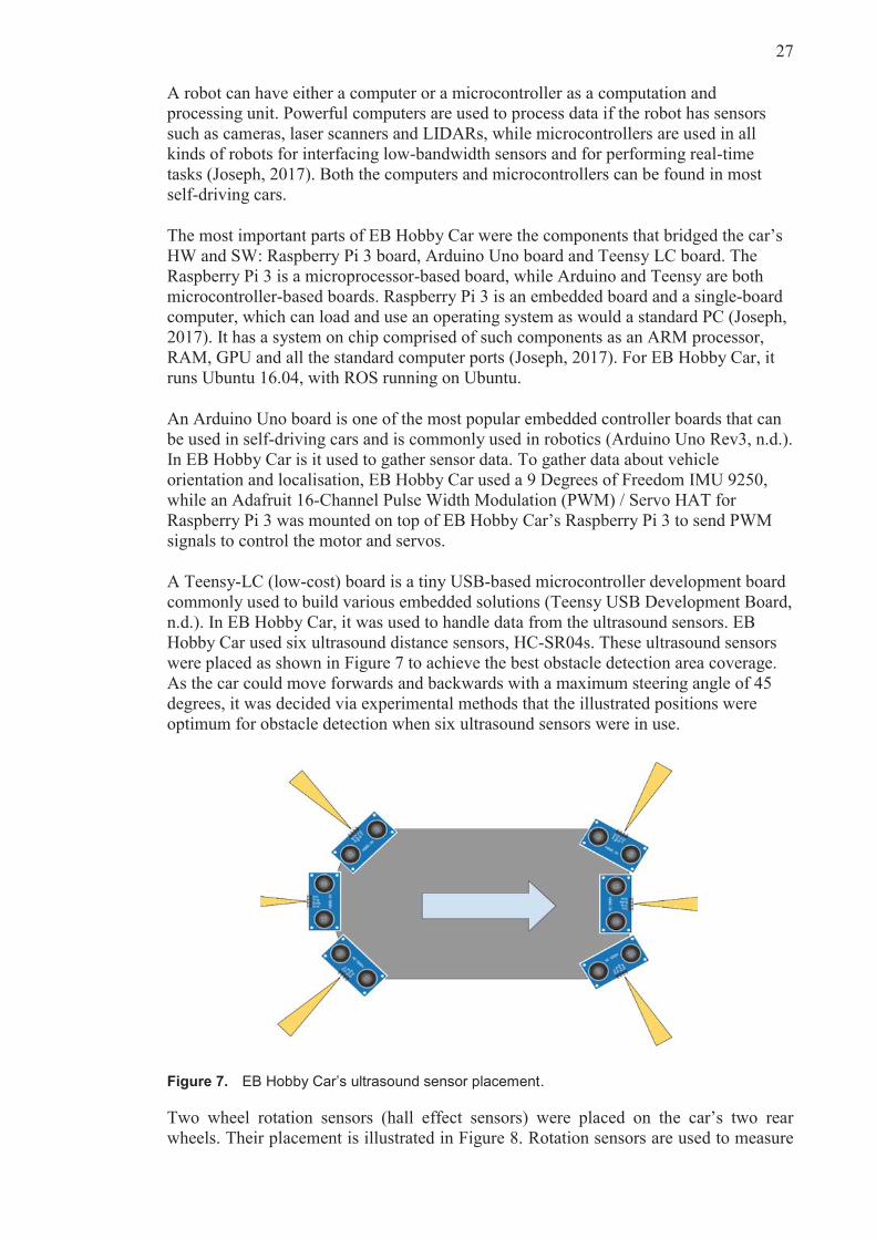
Hobby Car used six ultrasound distance sensors, HC-SR04s. These ultrasound sensors
were placed as shown in Figure 7 to achieve the best obstacle detection area coverage.
As the car could move forwards and backwards with a maximum steering angle of 45
degrees, it was decided via experimental methods that the illustrated positions were
optimum for obstacle detection when six ultrasound sensors were in use.
Figure 7. EB Hobby Car’s ultrasound sensor placement.
Two wheel rotation sensors (hall effect sensors) were placed on the car’s two rear
wheels. Their placement is illustrated in Figure 8. Rotation sensors are used to measure

28
speed and wheel rotation, and they can be used to perform a positioning process called
‘dead reckoning’. In this process, one sensor is placed on each side of the car to
compensate for different distances driven by the outer and inner wheels in a curve. The
direction of rotation is derived from motor input.
Figure 8. EB Hobby Car’s wheel rotation sensors placement.
EB Hobby Car used a Turnigy 1300mAh 2S 20C Lipo Pack battery to power itself.
During development and testing, the car often had to be running; because of this, two
batteries were used. One was always kept fully charged as a backup while the other was
in use. For image processing, EB Hobby Car used a Raspberry Pi Camera Board v2 - 8
Megapixels. It was mounted statically to have a view of the front of the car, as shown in
Figure 9.
Figure 9 illustrates the final look of EB Hobby Car, with its main HW components
marked. Here, the position and placement of the main HW components are visible. As
described, the final EB Hobby Car was equipped with six ultrasound sensors (three in
the front and three in the rear), two rotation sensors (one on the left and one on the right
rear wheel)—which also detected rotation direction—an IMU (containing a 3D
compass, acceleration, gyro and thermometer) and the Raspberry Pi camera.
Figure 9. Final look of EB Hobby Car with marked HW.

29
4.4 Designing the system structure
Figure 10 illustrates the network setup required for the development and control of EB
Hobby Car. To be able to connect to the car’s Raspberry Pi via Secure Shell (SSH)
protocol, while developing and testing, the Raspberry Pi and a remote PC had to be on
the same network. With the EB network closed, this required another network to be set
up; thus, 4G and a mobile hotspot were used. SSH connection was necessary during
development because had any cables been attached to the car, it would not have been
able to move freely.
Figure 10. Network setup for development and control of EB Hobby Car.
The system architecture of EB Hobby Car was devised from the requirements shown in
Table 3. All the data acquired by the sensors had to be made available for the on-board
computer, Raspberry Pi. This was achieved by writing low-level drivers, which
understood data coming from the sensors and made it available for high-level
processing. Low-level drivers for car’s movement were also developed. This made
high-level development based on the ROS possible.
Figure 11 illustrates how the sensors, motor and steering interfaced with the low-level
drivers and the ROS. Each ROS node communicates with the other nodes by displaying
the ROS nodes, ROS topics and ROS messages exchanged between them. The ROS
master node, roscore, is always active and responsible for registering the other nodes
and topics in the running ROS ecosystem.
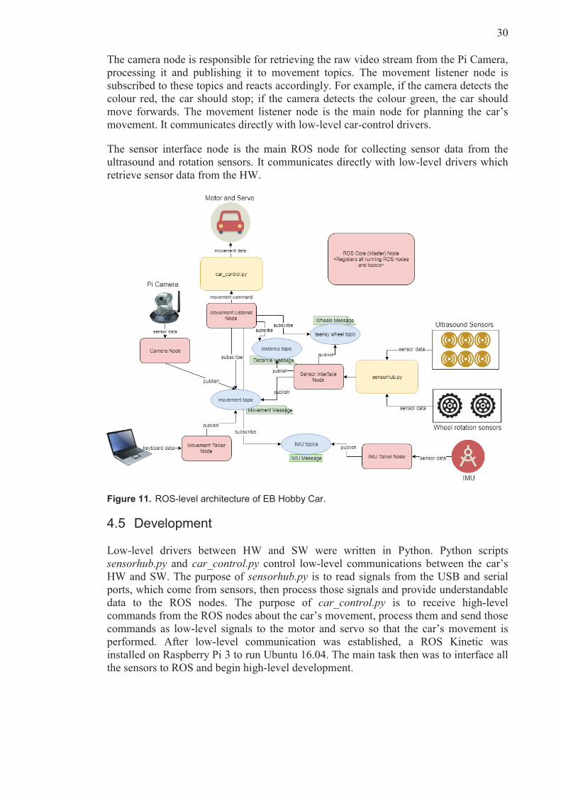
The IMU talker node is an ROS node responsible for gathering data from the IMU unit,
processing it and publishing it to IMU topics. The movement listener node is subscribed
to the IMU topics and retrieves the needed data to decide the car’s next movement. An example of the type of data that comes from the IMU talker node is heading data,
expressed in degrees from 0 to 360, which allows the car to know which way it is
heading according to the Earth’s magnetic field.
30
The camera node is responsible for retrieving the raw video stream from the Pi Camera,
processing it and publishing it to movement topics. The movement listener node is
subscribed to these topics and reacts accordingly. For example, if the camera detects the
colour red, the car should stop; if the camera detects the colour green, the car should
move forwards. The movement listener node is the main node for planning the car’s movement. It communicates directly with low-level car-control drivers.
The sensor interface node is the main ROS node for collecting sensor data from the
ultrasound and rotation sensors. It communicates directly with low-level drivers which
retrieve sensor data from the HW.
ROS-level architecture of EB Hobby Car.
4.5 Development
Low-level drivers between HW and SW were written in Python. Python scripts
sensorhub.py and car_control.py control low-level communications between the car’s
HW and SW. The purpose of sensorhub.py is to read signals from the USB and serial
ports, which come from sensors, then process those signals and provide understandable
data to the ROS nodes. The purpose of car_control.py is to receive high-level
commands from the ROS nodes about the car’s movement, process them and send those
commands as low-level signals to the motor and servo so that the car’s movement is
performed. After low-level communication was established, a ROS Kinetic was
installed on Raspberry Pi 3 to run Ubuntu 16.04. The main task then was to interface all
the sensors to ROS and begin high-level development.
31
4.5.1 ROS on EB Hobby Car
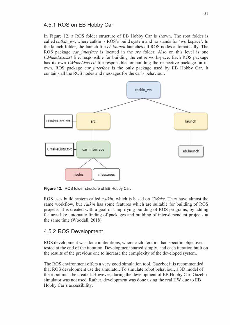
In Figure 12, a ROS folder structure of EB Hobby Car is shown. The root folder is
called catkin_ws, where catkin is ROS’s build system and ws stands for ‘workspace’. In
the launch folder, the launch file eb.launch launches all ROS nodes automatically. The
ROS package car_interface is located in the src folder. Also on this level is one
CMakeLists.txt file, responsible for building the entire workspace. Each ROS package
has its own CMakeLists.txt file responsible for building the respective package on its
own. ROS package car_interface is the only package used by EB Hobby Car. It
contains all the ROS nodes and messages for the car’s behaviour.
Figure 12. ROS folder structure of EB Hobby Car.
ROS uses build system called catkin, which is based on CMake. They have almost the
same workflow, but catkin has some features which are suitable for building of ROS
projects. It is created with a goal of simplifying building of ROS programs, by adding
features like automatic finding of packages and building of inter-dependent projects at
the same time (Woodall, 2018).
4.5.2 ROS Development
ROS development was done in iterations, where each iteration had specific objectives
tested at the end of the iteration. Development started simply, and each iteration built on
the results of the previous one to increase the complexity of the developed system.
The ROS environment offers a very good simulation tool, Gazebo; it is recommended
that ROS development use the simulator. To simulate robot behaviour, a 3D model of
the robot must be created. However, during the development of EB Hobby Car, Gazebo
simulator was not used. Rather, development was done using the real HW due to EB
Hobby Car’s accessibility.

32
Iteration 1: Manual control
The goal of the first iteration was familiarisation with the ROS environment and ROS
programming by developing the manual control of EB Hobby Car via the keyboard. The
following ROS messages, topic and nodes were written and used in this iteration:
ROS message Movement:
# command: forward, reverse, left, right, brake, reset string command
Here we see ROS topic /movement, ROS node movement_talker (which publishes to
the /movement topic) and ROS node movement_listener (which subscribes to the
/movement topic).
Figure 13 illustrates the ROS node movement_talker running in the terminal where the
user has the ability to publish movement messages to the /movement topic by pressing
certain keyboard buttons.
Figure 13. Movement talker node running in the terminal.
Below is a code snippet from the start of the movement_talker_node main method,
where a ROS node prepares to publish data to a ROS topic:
def main_loop(): rospy.init_node('movement_talker_node') pub=rospy.Publisher('movement_talker', Movement, queue_size=1) print(',---------------------------------------------') print('| Enter command: |') print('| w = throttle forward / s = throttle reverse |') print('| a = steer left / d = steer right |') print('| b = break |') print('| r = center steering |') print('| any other key = kill switch, STOP! |') print('| q = STOP and quit script |') print(' ---------------------------------------------')
while True: ch = getin() movement_msg = Movement()
33
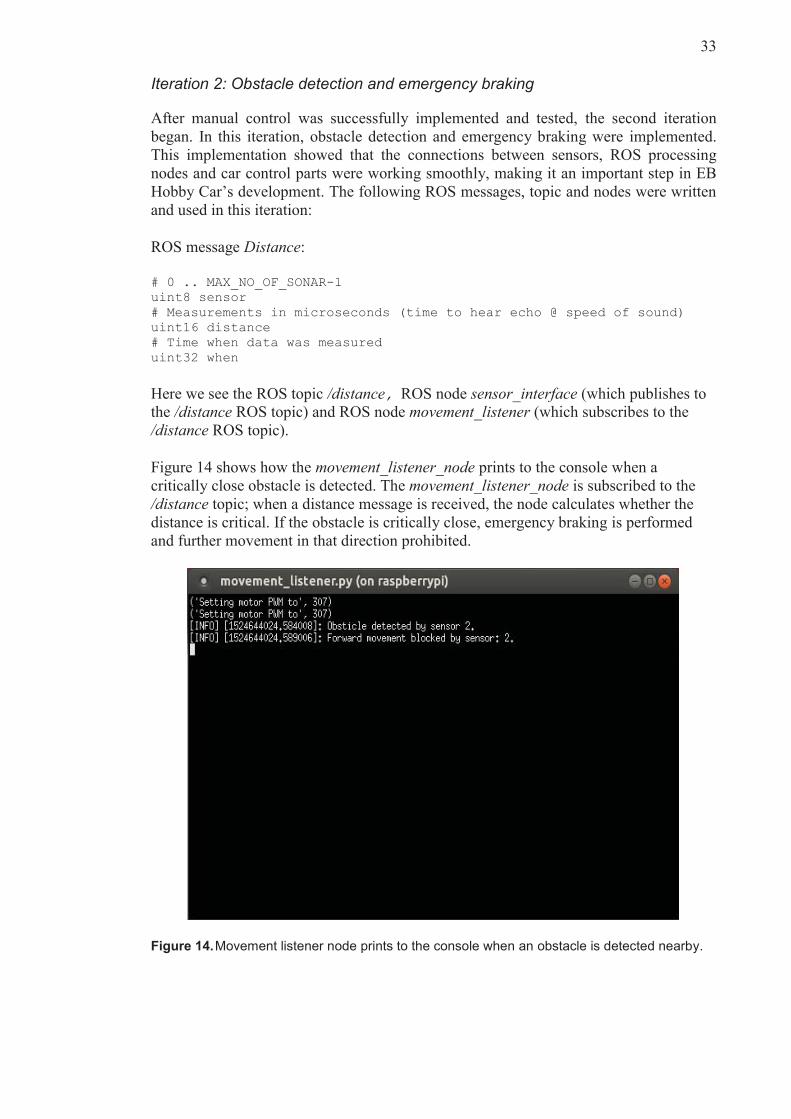
Iteration 2: Obstacle detection and emergency braking
After manual control was successfully implemented and tested, the second iteration
began. In this iteration, obstacle detection and emergency braking were implemented.
This implementation showed that the connections between sensors, ROS processing
nodes and car control parts were working smoothly, making it an important step in EB
Hobby Car’s development. The following ROS messages, topic and nodes were written
and used in this iteration:
ROS message Distance:
# 0 .. MAX_NO_OF_SONAR-1 uint8 sensor # Measurements in microseconds (time to hear echo @ speed of sound) uint16 distance # Time when data was measured uint32 when
Here we see the ROS topic /distance, ROS node sensor_interface (which publishes to
the /distance ROS topic) and ROS node movement_listener (which subscribes to the
/distance ROS topic).
Figure 14 shows how the movement_listener_node prints to the console when a
critically close obstacle is detected. The movement_listener_node is subscribed to the
/distance topic; when a distance message is received, the node calculates whether the
distance is critical. If the obstacle is critically close, emergency braking is performed
and further movement in that direction prohibited.
Figure 14. Movement listener node prints to the console when an obstacle is detected nearby.

34
In the main loop, the movement_listener_node subscribes to four different topics and
handles them in separate call-back functions, as seen from the code snippet below. This
code snippet also illustrates how the ROS node subscribes to a ROS topic.
def movement_listener(): rospy.init_node('movement_listener_node',anonymous=True) rospy.Subscriber(MOVEMENT_TOPIC_NAME,Movement,movement_cb) rospy.Subscriber(DISTANCE_TOPIC_NAME,Distance,distance_cb) rospy.Subscriber(WHEEL_TOPIC_NAME,Wheels,wheels_cb) rospy.Subscriber(IMU_TALKER_TOPIC_NAME,ImuMessage,imu_message_cb) rospy.spin()
An example handler code could look like this:
def imu_message_callback(data): global heading, roll, pitch heading = data.heading roll = data.roll pitch = data.pitch print('Heading={0:0.2F}Roll={1:0.2F}Pitch={2:0.2F}'.format(heading, roll, pitch))
Iteration 3: Pi camera colour detection
The goal of the third iteration was to use the Pi camera to detect colours. The idea was
that, in future work, this function would be used to detect traffic light colours and other
traffic signals. The successful implementation of this iteration provided the proof of
concept that the Pi camera can be interfaced with the ROS and used for image
processing.
Figure 15. Screenshot from the video obtained by the ROS node camera_talker.

35
In Figure 15, a screenshot from the video obtained by the ROS node camera_talker can
be seen. The following ROS messages, topic and nodes were written and used in this
iteration:
ROS message Movement:
# command: forward, reverse, left, right, brake, reset string command
Here we see the ROS topic /movement, ROS node camera_talker (which publishes to
the /movement ROS topic) and the ROS node movement_listener (which subscribes to
the /movement ROS topic).
Iteration 4: Wheel rotation sensors
In the fourth iteration, wheel rotation sensor data was used to obtain information about
how far each wheel travelled. First, wheel odometry calibration was performed.
Calibration is required in odometry to reduce navigational errors. The main parameter
for calibration is the measure of ‘distance per encoder ticks of the wheels’ (Joseph,
2015). Joseph (2015) explains this measure as the distance traversed by the car’s wheel during each encoder tick.
Figure 16. EB Hobby Car in the process of odometry calibration.
The process of odometry calibration for EB Hobby Car can be seen in Figure 16. To
calibrate the car, it was driven for a fixed distance (e.g. as illustrated in Figure 16, EB
Hobby Car drove for one meter) while the encoder counted the left and right wheels.
The following equation gave an average count per millimetre:
Counts per millimetre = (left counts + right counts)/2)/ total millimetre travelled

36
The following ROS messages, topic and nodes were written and used in this iteration:
ROS message Wheel:
# Two records, one for left and one for right wheel OneWheel left OneWheel right
ROS message OneWheel:
# Pulses per second (lowest possible speed is 20 seconds for one wheel revolution) uint16 speed # Enumeration rotDirection is used uint8 direction # Timestamp for measurement uint32 when # Odometer when direction changed uint32 dist # Absolute distance travelled uint32 dist_abs
Here we see the ROS topic /teensy_wheel, the ROS node sensor_interface publishes to
/teensy_wheel topic and the ROS node movement_listener subscribes to the
/teensy_wheel topic.
In Figure 17, data received from the /teensy_wheel topic can be seen printed in the
movement_listener node.
Figure 17. Data from /teensy_wheel topic received and printed in movement_listener node.

37
Iteration 5: 3D model of EB Hobby Car
The ROS grants access to a whole system of tools to support robot development. Within
this system are simulation tools such as Gazebo, which allow for robotic SW to be
developed without running it in actual HW.
Use of these simulation tools requires a model of the robot. The model can be defined in
varying levels of detail, but at minimum it should specify all the model’s moving parts
(links) and how they are connected (joints). The visual aspects of the model are less
relevant for the simulation, though it is possible to include purely visual elements so
that the model looks like the real thing.
The most common way for modelling when using an ROS is unified robot description
format (URDF). A URDF ROS package has XML specifications upon which one can
choose model of the robot, sensors, scenes, et cetera (Coleman, 2014). Simply put,
when using URDF, one can describe and model one’s own autonomous car using XML-
like syntax understood by the ROS. URDF allows the basic physical structure of the
robot, as well as its visual look and feel, to be modelled (Gazebosim, n.d.). Gazebo
actually uses a more comprehensive modelling format called Simulation Description
Format (SDF), but the recommendation is to start with URDF, because it works with
most of the available ROS tools and has the best ROS support (Gazebosim, n.d.). URDF
can be converted to SDF (Gazebosim, n.d.).
The following piece of XML code is a snippet from an rccar.urdf file used to describe
EB Hobby Car and create the car’s model.
<!-- Front left wheel --> <link name="front_left_wheel"> <collision> <origin rpy="1.5708 0 0"/> <geometry> <cylinder length="0.04" radius="0.055"/> </geometry> </collision> <visual> <origin rpy="1.5708 0 0"/> <geometry> <cylinder length="0.04" radius="0.055"/> </geometry> <material name="black"/> </visual> <inertial> <origin rpy="1.5708 0 0"/> <mass value="0.1"/> <inertia ixx="8.896e-5" ixy="0.0" ixz="0.0" iyy="8.896e-5" iyz="0.0" izz="1.515e-4"/> </inertial> </link> <gazebo reference="front_left_wheel"> <material>Gazebo/Black</material> </gazebo>
The visualisation shows the joints and their local coordinate axes, which makes it easy
to see whether they are located where expected. The model has all the basic moving
parts and joints that EB Hobby Car has, and its dimensions should be roughly correct.

38
The goal was to make the model move in Gazebo to enable the autonomous driving
algorithms to be developed in parallel with the actual car.
Figure 18. RVIZ visualisation of a simple model of EB Hobby Car, done in URDF.
ROS Visualisation (RVIZ) is a way of displaying sensor data and robot’s state
information from the ROS in a 3D manner. Figure 18 shows an RVIZ visualisation of a
simple model of EB Hobby Car in URDF.
Iteration 6: Localization and mapping
An autonomous car cannot navigate through an unknown environment without sensors
and an on-board computer which would make use of acquired sensor’s data to
understand the environment. Different kinds of sensors (such as sonars, odometers,
LIDAR, IMU, GPS and cameras) are used to make an autonomous car capable of
sensing a wide range of environments (Zaman, Slany, & Steinbauer, 2011). A map of
the environment is a basic need of an autonomous car to perform services like moving
from point A to point B (Zaman, Slany, & Steinbauer, 2011). While it is moving
through an environment, the car should also be aware of its own location in that
environment, and its own dimensions, to be able to solve navigation and route planning
issues successfully (Zaman, Slany, & Steinbauer, 2011).
Mapping of the environment. Environment mapping is done by creating the 2D model of
the environment surrounding a car using its sensors and mapping algorithms (Zaman,
Slany, & Steinbauer, 2011). The created map is then used for car’s localisation,
navigation and route planning.
Localisation. Car localisation tells the car where it is in relation to its environment.
Localisation uses odometry, laser data and a map (Zaman, Slany, & Steinbauer, 2011).
The localisation algorithms play a crucial role in the positioning. As input, localisation
algorithm requires a global map with occupied cells, a LIDAR, RADAR or ultrasound
sensor sweep and, optionally, an estimated location, which is usually obtained using the

39
dead reckoning algorithm (Zaman, Slany, & Steinbauer, 2011). If the estimated location
is not available, localisation will be performed using the full scale map, otherwise
localisation will be restricted to around the estimated location (Varveropoulos, 2005).
Dead reckoning. Dead reckoning is a location estimation algorithm that uses odometry
information. This is a is a very common approach to solving the localisation problem.
Even though it is fast and relatively easy to implement, dead reckoning is usually used
as a secondary source of location information, as it can be inaccurate (Varveropoulos,
2005). It is often combined with other localisation methods, to get more accurate results.
When combined with range sensor–based localisation algorithm, dead reckoning can
provide much better localisation results close to real time (Varveropoulos, 2005).
The ROS platform could greatly shorten the robot development cycle, and simultaneous
localisation and mapping (SLAM) could easily be realised using ROS (An, Hao, Liu, &
Dai, 2016). This is possible because ROS already has ready packages for this purpose
called gmapping. By using this package, ROS-based self-driving car could simply map
the environment by using LIDAR sensor (Gmapping, n.d.).
As EB Hobby Car was not designed with an LIDAR, use of this ready ROS package
was not possible. An alternative solution was to use ultrasound sensors to perform
SLAM. The problem was that mapping an environment using ultrasound sensors
outputs much poorer results than LIDAR mapping. This is because the ultrasound
sensors could pick up the returning signal from the other ultrasound sensor, which
would give inaccurate results (Mapping with sonar data, n.d.). Because of this, it is very
important how and where ultrasound sensors are placed. Additionally, bandwidth of
ultrasound sensors is smaller than of LIDAR sensors (Mapping with sonar data, n.d.).
Nevertheless, mapping of the environment using ultrasound sensors is in theory
possible, but was beyond the scope of this DSR. In the future, EB Hobby Car may be
equipped with LIDAR.
Iteration 7: Route planning
Once the environment map is in place and the car can locate itself with success, what is
left to do is to plan a route from point A to point B within that environment. Route
planning is one of the core functions of a self-driving car, where the car, ideally, finds
the shortest or optimal path between two points.
This process can be done using different route planning algorithms, depending on the
implementation and situation. If the whole map is already known, and will not change,
algorithms like Dijkstra or A* can be implemented to manage the navigation from point
A to point B (Paden, Michal , Sze , Yershov, & Frazzoli, 2016). Dijkstra’s algorithm is
one of the simplest algorithms which allows the car to find the shortest path from point
A to point B in a graph-like structure of the environment map (Feik, 2017). A*
algorithm requires a cost estimation along with the actual distance and the marked node,
is more efficient than Dijkstra’s algorithm and works better for occupancy grid maps.
(Paden, Michal , Sze , Yershov, & Frazzoli, 2016).
More complex algorithms, for example D* and Rapidly-exploring Random Trees
(RRT), are needed if the car needs to react to the changing environment map (Paden,
Michal , Sze , Yershov, & Frazzoli, 2016). D* algorithm is an extension of the A*
algorithm, which solves the issue of demanding recalculations that occur when car faces
unexpected obstacles in the path (Paden, Michal , Sze , Yershov, & Frazzoli, 2016). D*
is designed to efficiently recalculate the shortest path every time the graph-like map

40
changes using information from previous search efforts (Paden, Michal , Sze , Yershov,
& Frazzoli, 2016). RTT algorithm is the most efficient algorithm for route finding in
large environment maps (Akgun & Stilman, 2011). The RTT algorithm aims to
randomly explore a large area of the search space quickly with iterative refinements
(Akgun & Stilman, 2011).
Iteration 8: Creation of ROS launch files
The following launch file describes the eb_imu.launch ROS launch file used to start the
ROS nodes in EB Hobby Car:
<?xml version="1.0"?> <launch> <!-- Sensor Interface Node --> <node pkg="car_interface" type="sensor_interface.py" name="sensor_interface_node" output="screen" launch-prefix="xterm -e" /> <!-- Custom IMU Node --> <node pkg="car_interface" type="imu_talker.py" name="imu_talker_node" output="screen" launch-prefix="xterm -e" /> <!-- Movement Listener Node --> <node pkg="car_interface" type="movement_listener.py" name="movement_listener_node" output="screen" launch-prefix="xterm -e" /> <!-- Movement Talker Node --> <node pkg="car_interface" type="movement_talker.py" name="movement_talker_node" output="screen" launch-prefix="xterm -e" /> </launch>
This is launch file, eb.launch, launches when the command roslaunch eb.launch is
executed in the terminal. After the command is executed, the ROS master node starts
automatically and nodes sensor_interface_node, movement_listener_node,
imu_talker_node and movement_talker_node, all from the car_interface ROS package,
start automatically in separate terminals. Launch files are very useful, as without them,
each node would have to be started manually in a separate terminal. Doing so would
require much time, especially during development and testing when the whole system
must restart frequently.

41
The launch file eb_camera.launch includes the launch file eb_imu.launch, which means
that it does the same as eb_imu.launch and spawns the camera_talker ROS node. Figure
19 illustrates the desktop after execution of the roslaunch eb_camera.launch command.
As shown, the sensor_interface_node, imu_talker_node, movement_listener_node,
movement_talker_node and picamera_color_decetion_node are launched in separate
terminals and communicate using defined topics and messages.
Figure 19. Full-screen screenshot after launch file execution.

42
5. Evaluation
This section presents the evaluation of the developed artefact against the pre-determined
requirements. This involved recording the achievement status of each requirement
identified in Chapter 4, then an evaluation rationale for each reported achievement
status.
Adherence to the requirements was noted as follows:
R1: Car should have camera, ultrasound sensors, IMU, LIDAR, RADAR, GPS, wheel
encoders and an on-board computer.
Status: Partially achieved
Evaluation: EB Hobby Car had all the described sensors except LIDAR, RADAR and
GPS due to budget limitations.
R2: Car’s sensors should be interfaced with ROS.
Status: Achieved
Evaluation: All the available sensors were interfaced with ROS.
R3: Car should have motor and servo control interfaced with ROS.
Status: Achieved
Evaluation: EB Hobby Car’s motor and servo control were interfaced with ROS.
R4: Car should use standardised ROS messages in communication between ROS nodes.
Status: Partially achieved
Evaluation: One part of the ROS messages exchanged between the ROS nodes of EB
Hobby Car was that of standardised ROS messages, while others were custom ROS
messages. Because EB Hobby Car was not a standardised ROS robot and its HW not
standardised ROS HW, custom ROS messages were necessary.
R5: ROS launch files should be used to start ROS nodes.
Status: Achieved
Evaluation: EB Hobby Car used launch files to start ROS nodes. Launch files created
and used were: eb_imu.launch and eb_camera.launch.
R6: Car should be accessible remotely via another computer on the same network.
Status: Achieved
Evaluation: A remote PC was able access EB Hobby Car’s Raspberry Pi 3 via SSH.
They were both set to the same network, where EB Hobby Car was assigned a static IP
address.
R7: The car’s movement should be manually controllable using keyboard input.
Status: Achieved
Evaluation: ROS node movement_talker_node accepted keyboard input via the
terminal and sent the data to car_control.py driver, which then controlled the car’s
movement.

43
R8: The car should be able to detect obstacles.
Status: Achieved
Evaluation: EB Hobby Car was able to detect obstacles using its six ultrasound sensors
at the front and rear of the car.
R9: The car should be able to perform emergency braking if a critically close obstacle is
detected.
Status: Achieved
Evaluation: When the ultrasound sensors detected a critically close obstacle,
emergency braking was performed and further movement in the direction of that
obstacle was prohibited.
R10: The car should be able to recognise and react to different colours using the Pi
Camera.
Status: Achieved
Evaluation: Data obtained from the Raspberry Pi camera was processed by ROS node
picamera_color_detection.py, which then published the processed data to the
/movement ROS topic custom ROS message, Movement. When a red colour was
detected, the car performed emergency braking; when a green colour was detected, the
car moved forward. This is proof that the Raspberry Pi camera can be used for image
processing with ROS.
R11: The car should be able to turn in any compass direction.
Status: Achieved
Evaluation: Using the ROS node imu_talker_node, which published the ROS message
imu_message to the ROS topic imu_topic, the car received heading directions from the
IMU unit. This data was converted to floats ranging from 0.0 to 360.0 to represent angle
degrees. Using this data, the car knew in which direction it was to head. When
requested, the car could use this data to turn in the desired direction. When instructed to
turn at a certain angle, ROS node movement_listener_node first calculated whether it
was closer to steer left or right to reach the desired angle, then executed the command
and moved the car.
R12: The car should be able to navigate and return to its initial position in reverse steps.
Status: Not achieved
Evaluation: Not achieved due to time limitations.
R13: The car should be able to move in a given direction for a given distance, and then
stop.
Status: Achieved
Evaluation: Achieved by implementing functions which controlled the car’s turning to
a given direction and moving for a given number of meters. Orientation data received
from the IMU unit had to be transformed to a float value between 0 and 360 degrees,
and odometry data received from the wheel encoders had to be calibrated.
R14: The car should be able to perform a K-turn.
Status: Achieved
Evaluation: Achieved by implementing the following algorithm: steer in one direction
and go reverse for 90 degrees, then steer in the opposite direction and move forward for
90 degrees.

44
R15: The car should implement Ackermann steering.
Status: Not achieved
Evaluation: Not achieved due to time limitations.
R16: The car should implement route planning.
Status: Not achieved
Evaluation: As environment mapping was not completed, route planning could not be
implemented.
R17: The car should log sensor data.
Status: Achieved
Evaluation: EB Hobby Car logged all its received sensor data.
R19: An URDF model of EB Hobby Car should be created.
Status: Achieved
Evaluation: An URDF model of EB Hobby Car was created and visualised in RVIZ.
Both the URDF code snippet and RVIZ image are shown in Chapter 4.
R19: Mapping of the environment should be done by detecting obstacles’ positions in a 2D space.
Status: Partially achieved
Evaluation: The full implementation was not achieved, as explained in Chapter 4. To
implement it properly would have required LIDAR. An experimental implementation
using ultrasound sensors was partially completed as proof of concept.
R20: The car should be able to estimate its position based on its starting location.
Status: Achieved
Evaluation: Using wheel odometry and dead reckoning, the car was able to locate itself
in correspondence to the starting location.

45
6. Discussion
The objective of this research was to determine how ROS can be used in developing
autonomous driving and to identify the possible benefits and challenges of such
implementation. This research problem was approached through the DSR methodology.
System development was divided into cycles, and the development process was done
iteratively. The completed system was evaluated against the requirements identified in
Chapter 4. The results of the evaluation revealed that most of the requirements were
met, with few exceptions due to lack of HW and other limitations to be discussed in this
section (ways to fulfil the requirements will also be discussed).
In Figure 20, EB Hobby Car is shown in action. By the end of the experiment, EB
Hobby Car reached a level of automation, thereby demonstrating the design as a valid
prototype to answer the DSR’s research questions. The two research questions
established at the beginning of the thesis are answered and discussed below.
Figure 20. EB Hobby Car in action.
This DSR was conducted to answer the research questions asked in Chapter 1. The
answer to RQ1, how can ROS be used in the development of autonomous driving, was
addressed by the design part of this experiment. The autonomous RC car was developed
using ROS per the steps described in the DSR: collect requirements, assemble
mechanical and electronic parts, connect sensors and interface them to the ROS,
implement motor and servo control and set up obstacle detection algorithms,
environment mapping, localisation and route planning. This complex task was
simplified by ROS, which provided tested and reusable SW components for
autonomous driving.
The answer to RQ2, what are the benefits and challenges of using ROS to develop
autonomous driving, came from analysing the present literature review and from the

46
author’s observations during the DSR. Unlike conventional SW development platforms,
ROS focuses on usability and ease of installation, and has the advantage of being free
and open source (An, Hao, Liu, & Dai, 2016). However, a developer still must have at
least basic knowledge of distributed computing and programming to undertake designs
related to automated driving.
The main benefits of ROS identified from the literature and present experiment are that
ROS as a robotic programming platform is peer-to-peer, tool-based, multi-lingual,
‘thin’, free and open source (Quigley et al., 2009). These benefits are discussed in
Chapter 3. Further, ROS includes several ready-made packages for autonomous driving
that can be used off-the-shelf, making it an easy choice for autonomous car
development. Additionally, there are ready-made visualisation tools which make ROS
development of self-driving cars easier (Tellez, 2017).
As for identified challenges, it is already mentioned in Chapter 3 that ROS has a single
point of failure and that ROS network is not secure (Tellez, 2017). As these security
threats pose a big vulnerability of car’s software, they are being addressed in ROS
version 2 (Tellez, 2017). Another challenge of using ROS in development of
autonomous cars, is that it requires solid C++ or Python programming skills, as most of
the ROS packages are written in those languages. Additionally, ROS also requires basic
Linux knowledge, being that ROS is Linux-based meta-operating system. Because of
this, ROS learning curve might be steep for some developers.
A search of the related literature did not reveal a structured set of requirements for
developing autonomous driving. This thesis responds to this gap by offering a structured
set of requirements for developing an autonomous RC car using ROS. By following
these requirements, an autonomous RC car can be developed using relatively cheap HW
equipment and open-source SW such as ROS. The described design process thus
contributes to the existing knowledge base on the topic. Further, the present study’s
identification of the benefits and challenges of using ROS in autonomous driving
development represents yet another contribution of this research to the knowledge base.
The complete SW of EB Hobby Car is publicly available via the present author’s
GitHub account. The name of the GitHub project is ros_autonomous_car. It is
published as an open-source project under Massachusetts Institute of Technology (MIT)
licensing. As the MIT license is a permissive free SW license, reusability is very liberal
(MIT License, n.d.). As such, the EB Hobby Car’s SW may be freely distributed,
modified and run, so long as credit is attributed to the author. This SW also enriches the
existing knowledge base on the topic.
As for limitations, budget constraints meant that some of the HW was not acquired,
such as the LIDAR sensor. The lack of LIDAR limited the development of the EB
Hobby Car, as explained in Chapter 4. Further, the author did not have experience
developing autonomous driving using conventional SW development platforms to
compare with the current ROS-based development. As such, the present study’s implementation could only be evaluated against the requirements set in Chapter 4.
For the EB Hobby Car to be fully autonomous, it will require proper environment
mapping using LIDAR and route planning algorithms. Ways to implement these
features are described in Chapter 4. This should be done in future works, and all
encountered challenges (or potential challenges) should be reported.

47
7. Conclusion
The purpose of this thesis was to research how ROS can be used in the development of
autonomous driving and to gain insight into the benefits and challenges of such an
approach. The research used the DSR methodology to test the use of ROS in
autonomous driving by implementing the system as described in Chapter 4.
The devised system was an ROS-based autonomous RC car. Its implementation drew
from the requirements presented in Chapter 4, which were developed from the literature
and company requirements. The DSR’s design phase included planning the desired
system’s structure and workflow, acquiring components, assembling the mechanical and
electronic parts of the car and developing iterative SW using ROS. The following
evaluation assessed how well the system met the design requirements.
Results show that ROS-based autonomous driving is both a feasible and a working
concept. This thesis shows how ROS can be used to develop autonomous cars by
following the steps in this DSR, thereby answering the first research question. Chapter 6
reported on the benefits and encountered challenges when using ROS in autonomous
driving development during this DSR, thereby answering the second research question.
This research will assist in the complex task of coping with the issues of autonomous
driving. Though the present DSR-developed artefact was a small RC car, its main
technical issues were the same as those of a full-scale car. As such, the problems,
solutions, benefits and challenges discussed in this DSR are viable for ROS-based
autonomous cars of any size and environments of any type.
In this thesis, more benefits were observed than challenges regarding the use of ROS in
developing autonomous driving. Research on this topic should continue, as it can
benefit the autonomous driving community, both academic and commercial.

48
References
About ROS. (2018). Retrieved May 9, 2018, from ROS: http://www.ros.org/about-ros/
Ademovic, A. (2015). An Introduction to Robot Operating System: The Ultimate Robot
Application Framework. Retrieved May 10, 2018, from Toptal:
https://www.toptal.com/robotics/introduction-to-robot-operating-system
Akgun, B., & Stilman, M. (2011). Sampling Heuristics for Optimal Motion Planning in
High Dimensions. Georgia Institute of Technology.
An, Z., Hao, L., Liu, Y., & Dai, L. (2016). Development of Mobile Robot SLAM Based
on. International Journal of Mechanical Engineering and Robotics Research
Vol. 5, No. 1 , 47.
Arduino Uno Rev3. (n.d.). Retrieved May 31, 2018, from Arduino:
https://store.arduino.cc/usa/arduino-uno-rev3
Autonomous car. (2018). Retrieved May 10, 2018, from Wikipedia:
https://en.wikipedia.org/wiki/Autonomous_car
AutoRally. (2017). Retrieved May 30, 2018, from ROS Wiki:
http://wiki.ros.org/Robots/autorally
Clearpath Robotics. (2015). Intro to ROS. Retrieved May 9, 2018, from Clearpath
Robotics:
http://www.clearpathrobotics.com/assets/guides/ros/Intro%20to%20the%20Rob
ot%20Operating%20System.html
Coleman, D. (2014, October 12). URDF. Retrieved May 9, 2018, from ROS:
http://wiki.ros.org/urdf
Conley, K. (2012, February 3). Nodes. Retrieved May 9, 2018, from ROS:
http://wiki.ros.org/Nodes
Conley, K. (2012, February 3). Services. Retrieved May 9, 2018, from ROS:
http://wiki.ros.org/Services
Davies, A. (2017, July 11). Waymo has taken the humans out of its self-driving cars.
Retrieved May 10, 2018, from Wired: https://www.wired.com/story/waymo-
google-arizona-phoenix-driverless-self-driving-cars/
Feik, F. (2017). SLAM-Based Navigation of An Autonomous Driving Car. Technical
University of Munich.
Forouher, D. (2014, June 1). Topics. Retrieved May 9, 2018, from ROS:
http://wiki.ros.org/Topics
Gazebosim. (n.d.). URDF in Gazebo. Retrieved May 31, 2018, from Gazebosim:
http://gazebosim.org/tutorials/?tut=ros_urdf

49
Gmapping. (2018). Retrieved May 10, 2018, from ROS: http://wiki.ros.org/gmapping
Hallenbeck, K. (2017, February 27). ADAS Development Vehicle Kit. Retrieved May 9,
2018, from ROS: http://wiki.ros.org/Robots/ADAS_Development_Vehicle_Kit
Halonen, R. (2016). Formal Instructions for Master's Thesis. Oulu: University of Oulu.
Hevner, A. R. (2007). A Three Cycle View of Design. Scandinavian journal of
information systems, 19(2) , 4.
Hevner, A. R., March, S. T., Park, J., & Ram, S. (2004). Design science in information
systems research. MIS quarterly, 28(1) , pp. 75-105.
Hevner, A., & Chatterjee, S. (2010). Design research in information systems: theory
and practice (Vol. 22). Springer Science & Business Media.
Hughes, J. (2017, November 3). Car Autonomy Levels Explained. Retrieved May 9,
2018, from The Drive: http://www.thedrive.com/sheetmetal/15724/what-are-
these-levels-of-autonomy-anyway
Jamelska, M. (2017, August 3). RADAR vs. LIDAR sensors in automotive industry.
Retrieved May 9, 2018, from Stanford University:
https://mse238blog.stanford.edu/2017/08/mj2017/radar-vs-lidar-sensors-in-
automotive-industry/
Joseph, L. (2015). Learning Robotics Using Python. Packt Publishing Ltd.
Joseph, L. (2017). ROS Robotics Projects. Birmingham: Packt Publishing Ltd.
Kurzaj, D. (2016, August 26). Messages. Retrieved May 9, 2018, from ROS:
http://wiki.ros.org/Messages
Levinson, J., Askeland, J., Becker, J., Dolson, J., Held, D., Kammel, S., et al. (2011).
Towards Fully Autonomous Driving: Systems and Algorithms. Intelligent
Vehicles Symposium (IV) (pp. 163-168). IEEE.
Mapping with Sonar Data. (2012, August 17). Retrieved May 9, 2018, from ROS
Answers: https://answers.ros.org/question/41550/mapping-with-sonar-data/
MathWorks. (2018). Exchange Data with ROS Publishers and Subscribers. Retrieved
May 9, 2018, from MathWorks:
https://www.mathworks.com/help/robotics/examples/exchange-data-with-ros-
publishers-and-subscribers.html
MIT License. (2018). Retrieved May 10, 2018, from Wikipedia:
https://en.wikipedia.org/wiki/MIT_License
Paden, B., Michal , Č., Sze , Z., Yershov, D., & Frazzoli, E. (2016). A survey of motion
planning and control techniques for self-driving urban vehicles. IEEE
Transactions on Intelligent Vehicles, 1(1) (pp. 33-55). IEEE.
Quigley, M., Conley, K., Gerkey, B., Faust, J., Foote, T., Leibs, J., et al. (2009). ROS:
an open-source Robot Operating System. ICRA workshop on open source
software, vol. 3, no. 3.2 , 5.

50
Reddivari, H., Yang, C., Ju, Z., Liang, P., Li, Z., & Xu, B. (2014). Teleoperation control
of Baxter robot using body motion tracking. Multisensor Fusion and
Information Integration for Intelligent Systems (MFI), 2014 International
Conference (pp. 1-6). IEEE.
Robot Operating System. (n.d.). Retrieved May 9, 2018, from Wikipedia:
https://en.wikipedia.org/wiki/Robot_Operating_System
Schaerer, S. (2016, June 17). The AutoRally Platform. Retrieved May 10, 2018, from
ROS: http://www.ros.org/news/robots/autonomous-cars/
Schweber, B. (2018). The Autonomous Car: A Diverse Array of Sensors Drives
Navigation, Driving, and Performance. Retrieved May 9, 2018, from Mouser:
https://www.mouser.fi/applications/autonomous-car-sensors-drive-performance/
Tellez, R. (2017, September 29). How to Start with Self-Driving Cars Using ROS.
Retrieved May 10, 2018, from The Construct:
http://www.theconstructsim.com/start-self-driving-cars-using-ros/
Teensy USB Development Board. (n.d.). Retrieved May 31, 2018, from PJRC:
https://www.pjrc.com/teensy/
Thomas, D. (2014, May 22). Introduction. Retrieved May 9, 2018, from ROS:
http://wiki.ros.org/ROS/Introduction
TTU Advanced Robotics. (2010, May 17). Odometry and Encoders. Retrieved May 9,
2018, from TTU Advanced Robotics:
http://ttuadvancedrobotics.wikidot.com/odometry
Varveropoulos, V. (2005). Robot localization and map construction using sonar data.
The Rossum Project, (pp. 1-10).
Woodall, W. (2018, January 16). Rosbuild. Retrieved May 9, 2018, from ROS:
http://wiki.ros.org/rosbuild
Zakharenko, R. (2016). Self-driving cars will change cities. Regional Science and
Urban Economics, 61 , 26-37.
Zaman, S., Slany, W., & Steinbauer, G. (2011). ROS-based Mapping, Localization and
Autonomous Navigation using a Pioneer 3-DX robot and their relevant issues.
Electronics, Communications and Photonics Conference (SIECPC), 2011 Saudi
International (pp. 1-5). IEEE.