universally compliant method of rigless well plug and ... · plug and abandonment of “onshore”...
TRANSCRIPT

Universally Compliant Method of Rigless Well Plug and Abandonment
Prospectus

2
New Method of Using Proven Technology
| www.oilfieldinnovations.com
This page intentionally left blank

3
Oilfield Innovations Limited, June 2018
PROSPECTUS |
Abstract: The social cost of offshore well plug and abandonment (P&A) is extreme and could escalate by 150% to 354% (Boschee, 2014)15. “UK taxpayers are facing a £24 billion bill for decommissioning that threatens to wipe out the remaining value of UK North Sea oil and gas (Ward, Financial Times, 2017)1.” About 47% of decommissioning costs are well plug and abandonment (Thornton, 2017)8, so over £11 billion is attributable to well P&A. Well P&A is, literally, putting cement into a hole-in-the-ground, so why is it so expensive? The majority of that £11 billion cost is not for cement plugging of the wells but, instead, relates to the systematic selection of the most expensive, instead of the least expensive, offshore logistics. This fact is easily demonstrated by comparing relatively inexpensive “onshore P&A” to very expensive “offshore P&A,” for similar well architectures. Many industry proven offshore logistical alternatives exist; however, industry systematically selects the most expensive offshore logistical means for well P&A. Proponents of drilling rigs, which account
for 40% to 70% of construction and P&A costs (Canny, 2017)17, cite cement bond measurements and keeping risks as-low-as-reasonably-practical (ALARP); however, measuring the cement bond is regularly avoided during drilling rig P&A and quantitative risk assessment shows that lower cost well logistics, using fewer people protected by pressure containment systems, are safer (Håheim, 2003)9. To explain this conundrum to those financially authorising drilling rig P&A requires ordinary speech to avoid the confusing technical jargon of practitioners. With those terms of reference in mind, Oilfield Innovations Limited, a Scottish registered micro-company, seeks funding to qualify a safer and lower cost universal rigless P&A method that uses lower cost industry proven tooling and offshore production intervention logistics, combinable with the logistics of other decommissioning activities, to reduce P&A cost by 32% (Siems, 2016)21 to 60% (Varne, 2017)85 and put cement into a hole-in-the-ground according to present regulatory requirements and industry best practice so as to keep risks and legal liabilities as-low-as-reasonably-practicable.
Its not Rocket Science;Its putting cement intoa Hole-in-the-Ground.
KEEP CALM
OFFSHORE WELL P&A
Prospectus for Universally Compliant Rigless Well Plug and Abandonment Method
by Clint Smitha and Bruce Tungetb
Introduction
Many corporations and governments around the world are feeling the effects of revenue tax deductions associated with offshore tax expense.
Offshore may no longer be the most attractive play, as World Oil reported in March 2017, “Exxon Mobile is diverting about one-third of its drilling budget this year to (onshore) shale fields that will deliver cash flow in as little as three years, said Chairman and CEO Darren Woods”131.
In January this year, the Financial Times1 reported “UK taxpayers are facing a £24bn bill for decommissioning oil and gas fields in the North Sea, which threatens to wipe out remaining tax revenues from an industry that has been among the Treasury’s most reliable cash cows for the past four decades.”
A few weeks ago, BP’s Vice President of Decommissioning (Thornton, 2017)8 reported to the International Oil and Gas Producers (IOGP) well experts committee that 47%, over £11 billion, of that cost is well plug and abandonment (P&A).
BP also alluded to the prospect that the estimated £11 billion P&A cost (47%) could increase by the historic decommissioning cost escalation rate of 150% to 354% (Boschee, 2014)15, i.e. £16.5 billion to £1.25 trillion.
In the authors’ experience, it is quite common for a rig-based P&A cost estimate to increase by factors of 150% to 350% once work begins and the unpredictable internal condition of older well becomes evident during P&A.
Offshore P&A has the two (2) objectives of: i) putting at least two cement plugs into a hole-in-the-ground, and then ii) removing the above seabed well equipment, wherein the cost of accomplishing these two simple objectives for +/- 5,000 UK wells is over £11 billion or £2.2 million per well.
If you ask external or resident P&A “experts” why it costs so much? You will get a lot of unnecessary technical jargon that leaves you even more confused.
We agree with Einstein who said: “if you cannot explain a problem simply, you do not understand it well enough.”

4 June 2018 | OGTC Funding Request
Terms of Reference
RiserlessSubsea
RiserRiser Subsea& Platform
Rig Logistics (Red)
RiserlessSubseaRiserless Logistics (Green)
Platform Bridge& Crane fromJackup Barge& Wireline or
Coiled Tubing
Light WellInterventionVessel (LWIV)
& Wirelineor CoiledTubing
Helideck &Crane withWireline or
Coiled Tubing
Supply BoatWalk-to-Work
Gangway
Helideck &Supply Boat
Wirline & CapillaryCoiled Tubing with
in situ or mobile crane
Drilling RigJackup Cantilevered
over subsea or platform
Restored PlatformRig or Workover
Rig
DrillingRig
Proven O�shore Logistical P&A Alternatives
Figure 1 - Proven Offshore Logistical P&A Alternatives
What Drives Offshore P&A Cost
Plug and abandonment of “onshore” wells is relatively simple and low cost because you can drive up to the well with a truck mounted rig to quickly remove the tubing, place cement and cut off the near ground level production equipment at the top of the well (wellhead).
Conversely, “offshore” logistics are costly, time consuming and require traversing a vast and often hostile ocean environment, whereby companies are responsible for providing an inhabitable and safe working environment.
It is, in fact, “logistics” that drives the majority of the £11 billion cost of UK P&A and, unfortunately, arguments between P&A “experts” as to the need for rig or rigless P&A work-scopes (see Figure 5) is at the heart of systematic selection of the most expensive logistical alternative of drilling rig P&A.
A step change in offshore P&A cost requires significantly reducing offshore logistical costs, which means drilling rig logistics must be replaced by rigless P&A logistics combined with other decommissioning activities and/or traditional rigless well intervention logistics.
Using the various Figure 1 “rigless” logistical methods, experts within a combined decommissioning campaign of 176 of 360 well P&A’s and 92 of 109 structure removals, produced cost savings of 32% over more conventional methods used in the Gulf of Mexico (Siems, 2016)21.
Arguably, if more of the 360 wells had been riglessly plugged and abandoned, more than 32% savings could have been achieved given that drilling rig cost accounts for 40% to 70% of well construction and deconstruction expense (Canny, 2017)17.
For example, an ENI study, showed that the ease of operations and light weight equipment of a rigless light well intervention vessel (LWIV) provided a 50% cost savings (Karlsen, 2014)22, while more recent studies indicate 60% cost savings (Varne, 2017)85.
A 30% to 60% P&A cost savings of between £3.3 and £6.6 billion, before escalation, would result in average per well P&A cost savings of £660,000 to £1,320,000 across the £11 billion total cost for the UK’s +/- 5,000 wells.
Combining P&A with other decommissioning logistics requires rig-less P&A equipment whereby, for example, if qualifying Oilfield Innovations’ rigless P&A method to API 17N technology readiness level 7 (TRL-7) cost a £1 million, the capital investment would be returned within the first two well plug and abandonments.
A step change in UK P&A costs that returns billions to the Treasury can be achieved by riglessly delivering a rig-based P&A work scope and combining the logistics of rigless P&A with other decommissioning activities.
Different Experts may be Needed
Drilling rig logistics are relatively easy. An oil and gas company contracts a drilling rig contractor who mobilises a self-sufficient drilling unit, refurbishes an owned platform drilling rig or mobilises a workover rig onto a platform and together with existing contracts the company is, more or less, ready for P&A.
Almost everyone but the UK Treasury and taxpayers, who will need to make up the tax shortfall, are happy with the status quo.

5OGTC Funding Request |
Terms of Reference
www.oilfieldinnovations.com
Figure 2 - LeTourneau 116C Class Drilling Rigover a Small Platform in UK Southern North Sea
Figure 3 - Walk to Work System Horne Wren48 (Decom World)
Combining decommissioning and rigless P&A logistics will obviously cause consternation and anxiety within the industry, especially within Operator drilling departments.
How could saving billions in UK P&A costs be anything other than controversial when said savings will adversely affect peoples’ lives and jobs?
Conversely, many more peoples’ lives will be adversely affected when decommissioning wipes out the tax revenues from UK oil and gas and forces government austerity measures.
Keeping the status quo may be obviously easier but, according to the Financial Times, it may be the end of UK North Sea oil and gas tax revenues.
Accordingly, if external or resident P&A experts resist changing P&A practices, for the good of the United Kingdom, different experts may be needed.
Rig versus Rigless Logistics
For reference, Figures 2 shows the enormous size of a typical UK Southern North Sea (SNS) rig compared to a UK SNS platform. Figure 3 shows a similarly sized platform with a walk-to-work gangway from a floating vessel and Figure 4 shows a jack-up barge and bridge link to the same platform during the UK Horne Wren decommisioning48.
Based upon the size alone, you do not need to be a rocket scientist to see that the rig-based logistical costs of Figure 2 will be significantly greater than the rigless logistical costs of Figures 3 and 4.
The equipment on drilling rigs is designed for harsh “drilling” environments. Through Operator revenue P&A deductions, Tax Payers are paying for 100% of the rigs “drilling” equipment when only about 25% of the equipment is necessary for P&A.
Rigless P&A logistics require detailed planning to determine available workspace, well access, lifting needs, pumping capacity and other rigless logistical requirements for various service and equipment contracts before P&A can be combined with other decommissioning activities.
Unfortunately, Oil and Gas Operators do not presently allocate sufficient resources or time to carry out anything other than a status quo [rig-based] plug and abandonment (Jenkins, 2016)13.

6 June 2018 | OGTC Funding Request
Terms of Reference
Figure 4 - Barge Bridge Linked to UK SNS Horne Wren Platform (Tullow)48
While more front-end staff for rigless intervention engineering will be required, logistical and contracting services can be included within other decommissioning activities to minimise cost.
Figure 1 shows the various offshore logistical options that can be used. Small platforms in shallow waters can use supply boats and helidecks or walk-to-work motion compensated gangways, pictured in Figure 3, with in-situ or mobile cranes to place rigless wireline (Figures 21, 23, 28-29 and 42) or capillary coiled tubing equipment (Wilde, 2013)92 that can perform rigless P&A.
As shown in Figure 4, small platforms in shallow water can also be accessed riglessly using a bridge link to windfarm jack-up barges with cranes for placing wireline units on the platform and/or deck space for coiled tubing units (Figures 22, 23, and 30-32) spooled to platform wells with cranes or jacking and pulling units used for removal of above seabed production equipment (Figures 10, 24-25 and 33-35).
The cranes on jack-up barges can also be used for deploying subsea lubricator systems, remote operated vehicles and divers for shallow water subsea wells to perform riserless wireline or coiled tubing P&A as well as above seabed equipment removal.
Combining rigless P&A with other decommissioning activities is not new in the North Sea, as seen on Horne Wren48 decommissioning shown in Figures 3, 4 and 33, but it depends upon a company’s view of P&A legal liabilities.
Depending upon the size of the platform, various platform decommissioning activities may be carried out concurrently. For example, some platform equipment may be removed, changed or added to better facilitate P&A and various facilities decommissioning activities can be performed at the same time as well P&A (Siems, 2016)21.
Within deeper water, light well intervention vessels (LWIV), see Figure 23, can use subsea lubricators to riglessly P&A subsea wells (Varne, 2017)85.
Finally, larger platforms in deeper water can use their cranes and helidecks to mobilise people and rigless equipment onto the platform’s decks to avoid reactivating a decrepit drilling rig or to avoid mobilising a workover rig onto the platform.
Even when a fully functional drilling rig is available on a large platform, lower costs with less people and safer operations are achievable with rigless methods of through production equipment P&A involving fewer lifting operations that leave radioactive contaminated LSA / NORM (Woods99,1994; Sharkey100,2008; Mously101, 2009; Smith102, 2010, Barclay103, 2010; Crouch104, 2012) equipment within the well.
For example, Shell estimates that 10,900 tonnes of LSA/NORM contaminated tubing and 18,980 tonnes of casing, or a total of 29,880 tonnes of steel from well P&A, are being sent to shore (Consultation Draft, 2017)28, whereas such steel and radioactive material could have been left in-situ during decommissioning of the Alpha, Bravo, Charlie and Delta Brent platforms if rigless methods had been used.

7OGTC Funding Request |
Terms of Reference
www.oilfieldinnovations.com
P&ACement
Plug
In SituCasing
Hole-in-the-ground
ImpermeableStrong Rock
P&ACement
Plug
In SituCement
In SituCasing
Hole-in-the-ground
High SealantPlacement Friction
LoggingInterference
ControlLines
ImpermeableStrong Rock
In SituTubing
In SituCement
Conventional RiglessPlug and Abandonment
Scope-of-Work
Conventional RigPlug and Abandonment
Scope-of-Work
Figure 5 - Conventional Rig-based versus Conventional Rigless Scope-of-Work Differences for P&A
Work Scope Differences
As depicted in the Figure 5 plan view, a well is a hole-in-the-ground through which jointed steel casing is cemented and production equipment (tubing, valves, control lines, etc.) are inserted to control hydrocarbon flow and provide environmental barriers.
P&A plugs act like a “bath tub” plug keeping higher pressure fluids within the earth from draining into lower pressure atmospheric and water environments.
The work scope for rig-based well plugging is shown in the left frame of Figure 5 and the work scope for conventional rigless well plugging is shown on the right side of Figure 5.
Work scopes for drilling and workover rigs comprise removing the production equipment and casing to place a sealant (cement) across a single properly cemented steel tubular string (casing).
A rig-based P&A work scope is expensive not only because of the scale of logistics and rental equipment shown in Figure 2, but also because additional disposal costs are generated by rig-based cleaning, removal and disposal of radioactive scale contaminated production equipment.
Because the cost of generating and disposing of large volumes of waste onshore is less than the time cost of an offshore drilling rig, using rig time to minimise waste is uneconomic and reducing the amount of waste generated by P&A is rarely considered.
Conversely, a conventional rigless P&A scope-of-work comprises placing a sealant (cement) through and around in-situ downhole production equipment within casing before removing above seabed equipment.
Rigless P&A is substantially less expensive because the logistical and rental costs of the smaller and less complex equipment use minimal resources.
Generating waste within rigless P&A can be problematic due to a lack of space and resources and, therefore, waste minimisation is the rule rather than the exception and radioactive scale contaminated production equipment is left in-situ wherever possible.
Rigless P&A is by far the lowest present cost option but, unfortunately, current logging technology is not able to measure the quality of in-situ cement through multiple casings (Moeinikia, 2014)63 left within a rigless P&A work scope and the legal liabilities of P&A must be considered.
8 June 2018 | OGTC Funding Request
Terms of Reference
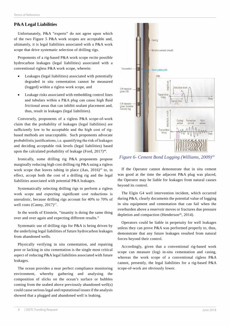
Figure 6- Cement Bond Logging (Williams, 2009)19
P&A Legal Liabilities
Unfortunately, P&A “experts” do not agree upon which of the two Figure 5 P&A work scopes are acceptable and, ultimately, it is legal liabilities associated with a P&A work scope that drive systematic selection of drilling rigs.
Proponents of a rig-based P&A work scope recite possible hydrocarbon leakages (legal liabilities) associated with a conventional rigless P&A work scope, wherein:
• Leakages (legal liabilities) associated with potentially degraded in situ cementation cannot be measured (logged) within a rigless work scope, and
• Leakage risks associated with embedding control lines and tubulars within a P&A plug can cause high fluid frictional areas that can inhibit sealant placement and, thus, result in leakages (legal liabilities).
Conversely, proponents of a rigless P&A scope-of-work claim that the probability of leakages (legal liabilities) are sufficiently low to be acceptable and the high cost of rig-based methods are unacceptable. Such proponents advocate probabilistic justifications, i.e. quantifying the risk of leakages and deciding acceptable risk levels (legal liabilities) based upon the calculated probability of leakage (Ford, 2017)44.
Ironically, some drilling rig P&A proponents propose marginally reducing high cost drilling rig P&A using a rigless work scope that leaves tubing in place (Aas, 2016)25 to, in effect, accept both the cost of a drilling rig and the legal liabilities associated with potential P&A leakages.
Systematically selecting drilling rigs to perform a rigless work scope and expecting significant cost reductions is unrealistic, because drilling rigs account for 40% to 70% of well costs (Canny, 2017)17.
In the words of Einstein, “insanity is doing the same thing over and over again and expecting different results.”
Systematic use of drilling rigs for P&A is being driven by the underlying legal liabilities of future hydrocarbon leakages from abandoned wells.
Physically verifying in situ cementation, and repairing poor or lacking in situ cementation is the single most critical aspect of reducing P&A legal liabilities associated with future leakages.
The ocean provides a near perfect compliance monitoring environment, whereby gathering and analysing the composition of slicks on the ocean’s surface or bubbles coming from the seabed above previously abandoned well(s) could cause serious legal and reputational issues if the analysis showed that a plugged and abandoned well is leaking.
If the Operator cannot demonstrate that in situ cement was good at the time the adjacent P&A plug was placed, the Operator may be liable for leakages from natural causes beyond its control.
The Elgin G4 well intervention incident, which occurred during P&A, clearly documents the potential value of logging in situ equipment and cementation that can fail when the overburden above a reservoir moves or fractures due pressure depletion and compaction (Henderson26, 2014).
Operators could be liable in perpetuity for well leakages unless they can prove P&A was performed properly to, thus, demonstrate that any future leakages resulted from natural forces beyond their control.
Accordingly, given that a conventional rig-based work scope can measure (log) in-situ cementation and casing, whereas the work scope of a conventional rigless P&A cannot, presently, the legal liabilities for a rig-based P&A scope-of-work are obviously lower.

9OGTC Funding Request |
Terms of Reference
www.oilfieldinnovations.com
Figure 7 - Pulse Reflection (Williams, 2009)19
Cement Bond Logging Measurements
NORSOK requires a minimum length of 30 metres measured depth for annular cement verification by cement bonding logs (Delabroy, 2017)27 and Oil and Gas UK guidelines2,30 specify a minimum of 100 foot (30m), if previously logged cement, or 1,000 feet (300m) of cement above the base of the intended barrier if estimated from original differential pump pressures.
Also, numerous Shell presentations publicly advocate the requirements of cement bond logging and, during the Aberdeen OGA Hackathon in June 2016, ConocoPhillips stated within its end-of-the-day summary that through-tubing-logging was the “holy grail” needed for compliant rigless P&A.
Unfortunately, current logging technology is not able to log through multiple casings (Moeinikia, 2014)63. Also, there are no accurate methods of determining cement levels in a rigless work scope for both tubing and annulus (Oil & Gas UK, 2015)2.
Williams19, et al., teach in Figures 6 and 7 that modern cement bond and variable density log measurement tools send low frequency omni-directional pulses that induce longitudinal vibrations in the casing. Receivers within the logging tools then record the reflected vibrations and when casing is bonded to hardened cement and rock, the vibration of the casing is attenuated and the reflected signal amplitude is relatively small.
Echoes and vibrations caused by unsecured and potentially eccentric and/or helically buckled production tubing are unpredictable and cannot be accurately separated from casing vibrations and, unfortunately, render bond and variable density logging tools unusable when the unsecured tubing is left in-situ.
Experiments show that it is possible to have sealant (cement) well placed in the annulus when tubing is left in the hole. Also, microannuli are relatively small and probably non-uniform. Furthermore, the presence of control lines may not represent additional leakage paths (Aas, 2016)25.
Unfortunately, while recent research shows that rigless P&A plug cementing through and around the tubing may be acceptable, it is a moot point because it is impossible to measure the integrity and quality of in-situ cement behind the casing without first moving the tubing.
Various authors (Woolsey53, 1988; Morlta54, 1992; Settari55, 2002; Williams19, 2009; Marbun56, 2011; King57, 2013; Feng52, 2016) have reported on the effects of well construction failures, reservoir compaction and changes in overlaying geology that can affect in-situ cementation and invalidate historical records of well construction.
Placing a useless P&A plug within casing with annuli leakages may exemplify gross negligence as, without log evaluations, there is little evidence otherwise. Evaluating cement in older wells can be particularly challenging (Smolen132, 1996; Benge65, 2014), but it legally documents P&A competency.
Accordingly, physically measuring in-situ conditions and cement bonding can comprise legal evidence usable to avoid claims of gross negligence should P&A wells ever leak, wherein defendants can blame natural causes for the leakages.
When production tubing is moved away from the casing, using a rig-based approach or, alternatively, using Oilfield Innovations’ patented rigless method, cement bond and variable density logging measurements are possible, whereas conventional rigless methods cannot assess the quality of in- situ cementation and, thus, may reduce present costs but not future legal liabilities associated with well leakages.

10 June 2018 | OGTC Funding Request
Terms of Reference
Barrier Elements
Height of 500ft MD, containing at least 100ft MD of Good Cement.
Good Practices
Good bond, clean surfaces, water wet
Support to prevent cement movement, slumping and gas migration while setting
Sealing plug of permanent material
Tubulars embeddedin cement
Sealing primary cementations
Formation:Impermeable &adequate strength to contain future pressures
“Restoring the Cap Rock”Permanent Abandonment Barrier (red dashed envelop)
Plug Depth determined by formation and primary cementation
Permanent Barrier (red dashed envelope)
Figure 8 -Good P&A Plug Practices (Oil & Gas UK, 2015)2
As-Low-As-Reasonably-Practicable (ALARP)
Oil and Gas producers may, in perpetuity, be legally liable for environmental pollution caused by well P&A when it is relatively easy to, in perpetuity, capture, analyse and confirm the source of a slick upon the ocean’s surface or hydrocarbons bubbling from the seabed.
Companies perceive legal liabilities differently and, therefore, a single industry-wide P&A standard does not exist and local requirements vary widely between prescriptive and goal setting regimes.
Generally, two (2) permanent P&A plug barriers to fluid flow are accepted when the zone requiring isolation is hydrocarbon-bearing or over-pressured and water-bearing.
Such primary and secondary (backup) barriers should be set above zone(s) with flow potential across a suitable caprock that is impermeable, laterally continuous and has adequate strength and thickness to contain the maximum anticipated pressures from the zone(s) being isolated.
Figure 8 shows that an Oil and Gas UK2 permanent barrier constitutes a good cement column of at least 100 feet (30 m) measured depth (MD). Where possible 500 feet MD barriers are set, presumably due to drilling rig P&A cement contamination when using a small diameter stinger (Rove, 2014)29.
Oil and Gas UK recites2 that at least 100 feet (30m) of
good annular cement should be verified by logging, but the industry trade group recognises the risk tolerance of their members varies and further recites that historic data can be used in a probabilistic manner to estimate whether good in- situ cement exists.
King57 and Ford44, et al., advocate “fit for purpose” risk-based approaches over prescriptive standards like NORSOK D-010. A risk-based approach means that any P&A solution is expressed in terms of the leakage risks shown in Figure 9, which can be formulated in terms of whether the (permanent) barrier system will fail in a given time period measured against the corresponding consequence in terms of leakage to the environment.
Unfortunately, risk-based P&A leak calculations may, or may not, comply with the UK legal precedents of keeping risks as-low-as-reasonably-practicable (Aguilar, 2016; Taylor, 2014)46,47.
Landmark UK legal cases in 1947 and 1954 established that “The test of what is (reasonably practicable) is not simply what is practicable as a matter of engineering, but depends on the consideration, in the light of the whole circumstances at the time of the incident, whether the time, trouble and expense of the precautions suggested are or are not disproportionate to the risk involved, and also an assessment of the degree of security which the measures may be expected to afford (Marshall v Gotham Co Ltd, 1 All ER 937 (HC) 1954).”

11OGTC Funding Request |
Terms of Reference
www.oilfieldinnovations.com
Figure 9 - Potential Leak Paths in P&A Plug(Gasda, 2004;Ford, 2017)43,44
Figure 10 - Rigless Pulling & Jacking Unit (PJU) ondamaged platform well (Canny, 2017)17
Elgin G4 well abandonment incident (Henderson, 2014)26 is evidential of how geological changes resulting from production depletion can cause hydrocarbon leakages from previously unproducible zones, wherein construing rig-based P&A to measure in-situ cement quality as a disproportionate sacrifice is ludicrous when other Operators typically use rigs for P&A cement quality measurements.
An annulus barrier is necessary for P&A and it does not matter whether the annular barrier is cement, shale (Willams29, 2009 Fjær111,2016) or salt (Lavery 2017)49. Provided logging measurements at the time of P&A can confirm an annular barrier, companies can prove that P&A was properly performed and the laws associated with disproportionality can be applied to the benefit of the Operator.
Hydrocarbon vs. Water Risk-Based Approach
Many authors (Lonnes66, 2009; King57, 2013; Taylor47, 2014; Guo64, 2014; Benge65, 2014; DNVGL-RP-E10314, 2016; Aguilar46, 2016; Ford44, 2017) discuss the merits and drawbacks of risk-based approaches to P&A.
Without delving into pedantic arguments, water and hydrocarbons are two different types of fluids with very different legal liabilities.
Adopting a risked based P&A approach for water bearing subterranean zones, located below the ocean far from any drinking water sources, can have negligible consequences given the impossibility of finding a water leak into an ocean, whereas catching, analysing and confirming the source of hydrocarbon slicks on the ocean surface or subsea bubbles leaking from a well P&A is realistically possible and has significant legal, reputational and cost consequences.
Using the Oil and Gas UK P&A Guidelines2 of accepting old construction records and using work by Aas25, et al., involving a risked based approach to leaving tubulars within the well during isolation of water bearing zones, below an ocean, has minimal legal liability; whereas the same cannot be said about P&A of hydrocarbon fluids which are lighter than water, naturally float to surface through any available leak paths and are easily identified at seabed and on the ocean’s surface.
Accordingly, a risk based approach to water bearing zones has few or no consequences, whereas the same cannot+ be said about hydrocarbon zones when accurately estimating any future event is impossible and the consequences of hydrocarbon leakages are substantial.
Regardless of risk-based versus traditional P&A approaches, or whether you believe isolating water bearing zones has a lower risk than isolating hydrocarbons, drilling rigs are not a P&A requirement. Rigless equipment is available for all P&A tasks, albeit there is no one-size-fits-all solution. For example, where Oilfield Innovations method cannot pull casing and conductors, rigless Pulling and Jacking Units (PJU) can, as pictured in the Figure 10 P&A being performed on a damaged wellhead platform (Canny, 2017)17.

12 June 2018 |www.oilfieldinnovations.com
Universally Compliant Rigless P&A Method
Hole-in-the-Ground
In Situ Cement(to be logged)
In Situ Casing
Weakening Cut
VerticallySplit TubingSplayed by
SpearTubing Spearsevered fromtubing string andforced downwardby piston
Plan View Elevation View
Ø13.375
Ø12.347
Ø9.625
Ø8.535
Ø9.625Ø8.535
Ø7.000Ø6.184
Ø9.625Ø8.535
Ø5.500Ø4.778
Ø9.625Ø8.535
Ø4.500Ø3.958
Ø7.000Ø6.059
Ø4.500Ø3.958
86.8%LiquidSpace
85.2%LiquidSpace
89.8%Liquid Space
93.7%Liquid Space
87.5%L.S.
9 5/8” inside 13 3/8”7” inside 9 5/8”
5.5” inside 9 5/8” 4.5” inside 9 5/8”4.5” inside 7”
RIGLESS TUBING COMPACTION TO CREATE LOGGING & CEMENT SPACE
drawn-to-scaleCOMMON NORTH SEA TUBULAR COMBINATIONS
In Situ Tubing
delivers rig-equivalentlogging and
cement space
Hydraulic Pressure& Inflatable Piston
force Tubing Spearinto Split Tubing
Rig-Equivalent Window:
Figure 11 - Plan View: Universal Method of Rig-Equivalent Rigless Abandonment
Universal Rigless P&A Method
Step changes in P&A cost require stopping the systematic selection of drilling rigs for P&A through Operator Corporate Management and Governmental influence away from the status quo.
Oilfield Innovations have patented a rigless P&A method, shown in the Figures 11 & 12, that compacts portions of downhole production tubulars into the 80% to 90% liquid spaces of a well to form a “Rig-Equivalent-Window” free of tubular interference for compliance logging and cementing, whereby the logistics of rigless P&A can keep legal liabilities and risks as-low-as-reasonably-practicable and remove arguments for using drilling rigs to, thus, allow Oil and Gas Operator Corporate Management and Government guidance for combining rigless P&A with other decommissioning activities and logistics to reduce the total offshore UK P&A cost by 30% to 60% (£3.3 to £6.6 billion).
The lower half of Figure 11 illustrates various common North Sea tubular combinations, which have 85% to 93% liquid space within the inner circumference of an outermost casing. Oil Country Tubular Goods (OCTG) are used worldwide and have standardized proportions and
combinations that are typically between 80% and 90% liquid space, which makes our P&A method universally applicable.
Creating the Figure 11 “Rig-Equivalent Window” provides a rig-based P&A work scope, shown in Figure 5, where unobstructed logging measurements of in-situ cement, shale (Willams29, 2009; Fjær111,2016) or salt (Lavery 2017)49 annulus barriers can riglessly occur to provide legal evidence that, so-far-as-reasonably-practicable, safe and environmentally responsible P&A occurred.
Split, weakened and severed tubing can easily be compacted into the 80% to 90% liquid spaces of a well to form a Rig-Equivalent-Window for proven conventional logging measurements confirming placement of a compliant P&A plug, as further illustrated in Figure 12 elevation view.
Explanatory Method Steps
The various steps of Oilfield Innovations’ universal rigless P&A method of in-situ cement verification and plugging illustrated in Figure 12 elevation view are similar or equivalent to other common downhole operations.
Step #1 of Figure 12 depicts vertically splitting in-situ production tubing to remove the strength of its circular shape, wherein the step requires qualification.

13June 2017 |
Universally Compliant Rigless P&A Method
www.oilfieldinnovations.com
VerticalSplit
BridgePlug
To PushAgainst
PumpPressureForcesPiston
DownwardThru-Tubing
InflatablePackermade of
a materiallike your
Car’s Tyrewith metal
slatsprotectingelastomerelements
A valve inthe packer(piston) or
perforationsin the casingor injection
into thereservorprevent
hydrauliclocking
The pistonscrapes andfluid cleansthe casing
duringcompaction
TubingSlumps
CirculateCleaning
Fluid
Thru-TubingLogging
of cementbehindcasing
RIGEQUIVALENT
WINDOW
Packer sealsagainst gasmigration
and supportscement plug
CementPlug
placed thruexistingTubing
Whereinsufficent
tubing slumpoccurs, thepacker canbe inflated
in the tubing,which can bepressurizedto push thesplit tubingdownwardto causeslumping
All wellshave
1000’sof metres
or feetof Tubing
Wthetherit is a
ProductionPacker orprevious
cement plugthe tubing iscompacted
into afixed
position
Step #1 Step #2 Step #3 Step #4 Step #5 Step #6
SeveredTubingSpear
Figure 12 - Elevation View: Universal Method of Rig-Equivalent Rigless Abandonment
Step #2 of Figure 12 illustrates the “common task” of severing the tubing above the split and circulating a cleaning fluid into the annulus space between the tubing and casing.
Step #3 of Figure 12 shows the “common task” of placing a mechanical plug for the subsequent packer (piston) to push against and then severing above the mechanical plug to create a tubing spear that can be pushed alongside the split tubing. Oilfield Innovations have proved the concept a tubing spear.
Step #4 of Figure 12 depicts the “common task” of inflating a packer in the casing and hydraulically pumping fluid into the well to push the packer (piston) downward to force the tubing spear alongside the split tubing, wherein the step of
using proven inflatables packers requires qualification.
Step #5 of Figure 12 illustrates “common” through tubing logging measurements of the in-situ cement within the Rig-Equivalent-Window space created to measure cement bonding. Alternatively, research shows that shale (Willams, 2009)29 or salt (Lavery 2017)49 can also comprise an annulus barrier that can be confirmed by logging measurements.
Step #6 of Figure 12 shows “common” placement of a P&A sealant (cement) plug that is supported by the compacted tubing, whereby the packer element’s casing seal prevents gas migration during sealant curing (hardening) to provide a universally compliant P&A plug.

14 June 2018 |www.oilfieldinnovations.com
Universally Compliant Rigless P&A Method
Figure 13 - Proof of Concept
Run
Yield Strength
Stress
Ultimate Strength
Strain Hardening Necking
Young’s Modulus =RiseRun
= Slope
Strain
Fracture
Yield and Ultimate Strength
1,660-psi
57.2 in2
1,398-psi
9.625 Csg Piston Area = 57.2 in2
80,000-lbf = 1,398-psi (96.4 bar)
4.5” API 12.6-ppf L80 Tubing
57.2in2
95,000-lbf = 1,660-psi (114.5 bar)
TRL 4 Compaction TrialsFull Scale Proof of Concept
There is nothing magical about the precisely defined properties of oilfield steel tubulars.
Oilfield Innovations method is not rocket science, it uses a piston to bend cut metal. Finding anything more simplistic may be impossible.
Oilfield Innovations have performed TRL-3 experiments20 and TRL-4 Full Scale Trials shown in Figure 13 and found that axially splitting tubulars decreased compaction resistance and resulted in tubular compaction ratios of near 50% in “worst case” horizontal conditions with as low as 500-psi pressure for 4.5 inch L80 tubing inside 9.625 inch casing, see Figure 15.
The predominate North Sea production casing size for P&A plugs is 9 5/8 inch (244.5mm) casing, which has a piston area of 57 in2 (368 cm2) and can provide enormous piston forces (see Appendix B Figure 40).
API Specification 5CT defines the properties of oilfield steel tubulars. The Figures 13 and 15 crushed L80 4.5” 12.6-ppf tubing had a minimum yield strength of 80,000-psi (551.6 N/mm2) and a maximum yield strength of 95,000-psi (655 N/mm2). Yielding 1in2 (6.5 cm2) of L80 steel requires forces between 80,000-lbf (355 kN) and 5,000-lbf (423 kN), which can be divided by the piston’s cross-sectional area of 57.2 in2 (369 cm2) to determine compaction pressures of 1,398-psi (96.4 bar) and 1660-psi (114.5 bar).
During the Figure 13 tubing compaction simulation, bending momentarily peaked to 2,000-psi (137.9 bar) due to piston friction, but then fell to average about 500 psi (34.5 bar) until reaching a 8% compaction ratio when the pressures increased again as shown in Fig. 15.
The North Sea predominantly uses tubing sizes of 4 ½ inch (114.3mm) and 5 ½ inch (139.7mm) outside diameter with steel grades of L80 or P110. API grade L80 steel has a minimum yield of 80,000-psi (551 N/mm2) and maximum yield of 95,000-psi (655 N/mm2). API grade P110 steel has a minimum yield of 110,000-psi (758.4 N/mm2) and maximum yield of 140,000-psi (965.3 N/mm2).
OGTC funded full scale Technology Readiness Level (TRL) 4 trials near Aberdeen Scotland trialled compacting both 4.5” and 5.5” L80 13Cr API specification tubulars within 9.625” casing to demonstrate that compacting such tubular to 50% of the original length is realistic.
North Sea wells are typically designed for pressures of 5,000-psi (344.7 bar) or 10,000-psi (689.5 bar) and can easily accommodate similar pressures measured within the full scale trials.
Accordingly, there is no doubt that tubulars can be compacted into the 80% to 90% liquid space of a well. As shown in Figure 14, it is only a matter of cutting tubulars to reduce the bending areas of steel with known properties.
Oilfield Innovations is also working with Oil and Gas Innovation Centre (OGIC), the University of Glasgow and the Oil and Gas Technology Centre (OGTC) to perform further mathematical simulations as discussed in Appendix A.
Additionally, TRL-2 work for a vertical cutter has been completed and TRL-3 work started with regard to developing an axial cutting tool to facilitate compaction.
Further technical justification with answers to frequently asked questions can be found in Appendix B and Oilfield Innovaitons can provide the TRL 4 Full Scale Tubular Compaction Trials Report upon request.

15June 2017 |
Universally Compliant Rigless P&A Method
www.oilfieldinnovations.com
Figure 14 - Splitting and Weakening of Tubulars to Reduce Compaction Forces or Facilitate Repair
Splitting Vertical Cut Shredding Vertical Cuts
Stacked & AlignedVertical Cutters
Tubing
Casing
Vertical Cutter
StackedVerticalCutters
Stacked & PhasedVertical Cutters
Weakening Vertical CutMinimizes Required Bending Force
Split & Weakening Tubularlessens necessary bending
to a hinge-like area
Multiple Wall Splitting Cuts or Multiple Weakening Cuts with a Single Split
What we have and what we need
Drilling rigs account for 40% to 70% of construction and P&A cost (Canning, 2017)17 and removing the reasons for selecting drilling rigs could save Operators and Governments billions.
Only logging measurements of in-situ cement can remove legal liabilities of P&A and, because our rigless method can provide the legal security of a rig-based P&A, our patents have a significant “enabling” value to Operators and the United Kingdom that could be as much as £3.3 to £6.6 billion.
Development costs for our method are infinitesimal compared to the savings, which could be recovered within the first two wells abandonments.
Rigless P&A methods have been available for many years, yet large Operators will not use them to reduce P&A cost.
Operators select drilling rigs to avoid the legal liabilities of not measuring in-situ cement during P&A.
That paradigm needs to change.
Oilfield Innovations have a method enabling in-situ cement verification but need funding to qualify a simplistic method of cutting and bending tubulars walls into a relatively large space to provide a rig-equivalent work scope using rigless P&A equipment that can be combined with other decommissioning activities and logistics.
Our method allows Operators to divert P&A funds to exploration and production drilling, Scotland could establish itself as the worldwide centre of excellence for P&A and the
toxic labels placed upon UK North Sea assets burdened by decommissioning liabilities could be removed so that smaller companies could assume ownership and continue production.
Cutting and weakening tubulars creates a simple hinge as shown in Figure 14. Bending a split piece of tubing is not difficult and spearing a whole piece of tubing into the 80% to 90% liquid space is equally simple (see Figures 11 and 12). The properties of steel are known and we have proven the concept proven (see Figures 13 and 15), but we understand that people want to see it for themselves.
Oilfield Innovations has with OGIC support funded a mathematical modelling project (see Appendix A), but will not be able to self-fund construction of a vertical cutter or TRL 5 compaction trials and will need full funding support.
Oilfield Innovations comprises two (2) engineers who own patented legal protection for cutting and using a piston to bend steel within a hole-in-the-ground to provide a space for regulatory compliant logging and cement. Unfortunately, we have gone as far as our limited resources allow.
Oilfield Innovations may be able to get State Funding support for development, but we will need matching development funding and support from Operators, Service Providers and/or Venture Capitalists.
Whether you consider cutting and bending steel with a piston to be new technology, or not, developing new technology just doesn’t get any simpler or have any higher rates of return.
We would need to understand the objectives and financial requirements of funding, but we are flexible and willing to explore various arrangements between New Technology

16 June 2018 |www.oilfieldinnovations.com
Universally Compliant Rigless P&A Method
450
650
850
1.05⋅10³
1.25⋅10³
1.45⋅10³
1.65⋅10³
1.85⋅10³
50
250
2.05⋅10³
440 475 510 545 580 615 650 685 720370 405 755
⋅1.281 103
⋅2.029 103
351
231
375 411 638 743670
vol9 ( )
pres9⎛⎜⎝―
2
⎞⎟⎠
pips9⎛⎜⎝―
2
⎞⎟⎠
48% Compaction
+/- 500-psi average Compaction Pressure
Figure 15 - TRL 4 Trials Compaction Pressure 4.5” Tubing compacted inside 9.625 Casing
Organisations, Operators, Service Companies and/or Venture Capitalists.
We are marketing our patents to cover tool development, test well and field trial qualification costs.
Oilfield Innovations contribution can comprise: selling patents to pay for development, using the patents as collateral for financing development, or transferring the patents to qualified company(s) who can match governmental development funding requirements.
Oilfield Innovations can offer a low-cost simple universal solution to verifiable P&A, but we can’t change the system. The systematic selection of drilling rigs for P&A needs to change and only the Operator Corporate Management and Government can influence that change.
Conclusion
As demonstrated in the TRL 4 Trial shown in Figure 15, Tubular Compaction can be used to perform P&A using relatively low pressures. Now is the time for change in the North Sea and combining universally compliant rigless P&A with other decommissioning activities is something that can save Operators and the UK government billions. The most challenging aspect is the industry’s natural resistance to change.
It is no coincidence that drillers systematically recommend drilling rig P&A and ignore published lessons in rigless
P&A (Coronado78, 1991; Edmondson96, 1996; Olsen79, 2001; Foster86, 2001; Khurana5, 2003; Håheim9, 2003; Munkerud71, 2007; Lonnes66, 2009; Jøssang72, 2010; Fjærtoft80, 2011; Flett87, 2011; Zwanenburg94, 2012; Zijderveld73, 2012; Morrison74, 2013; Willis75, 2013; Osorio81, 2013; Wilde92, 2013; Birk95, 2013; Krüger76, 2014; Karlsen22, 2014; Webb93, 2014; Løver77, 2015; Loov82, 2015; Webb83,2015; McLeod88, 2015; Stein70, 2016; Numbere84, 2016; Rivas89, 2016; Mackie91, 2016; Varne85, 2017; Tanoto109, 2017).
Drillers are comfortable using drilling rigs for P&A and letting Corporations and Governments pick up the P&A bill.
Drilling rig cost accounts for 40% to 70% of well and P&A costs (Canny, 2017)17 and, therefore, all rig-based operations are justified based upon the rig time needed to complete a task.
When asked to reduce time and cost, drilling rig P&A proponents recommend Perf & Wash (Ferg32, 2011; Abshire69, 2012; Khalifeh68, 2013; Moeinikia63, 2014; Aas25, 2016; Delabroy27, 2017) to avoid long and costly cutting, milling and pulling operations that may, or may not, be necessary.
What the drillers don’t tell you is that Perf & Wash provides a rigless work scope that could have been accomplished without using a drilling rig costing 40% to 70% of the total P&A expense.
People naturally fear change and use technical jargon that sounds like rocket science to keep the status quo; however, when the simple problems are answered P&A becomes easy.

17June 2017 |
Universally Compliant Rigless P&A Method
www.oilfieldinnovations.com
Further Information
Addition detailed information on the Oilfield Innovations’ rigless P&A method described above is included in Appendix B, please provide this document to your engineers and we would be happy to answer any further queries. For additional information or further queries please contact Clint Smith or Bruce Tunget at the below email addresses.
Notes and referencesa Clint Smith is Professional Engineer in the State of Texas, began working in the Drilling, Intervention and Well Operations in 1978 and lives in Houston, Texas, USA; Curriculum Vitae (CV) available upon request; [email protected]
b Bruce Tunget earned a PhD. and MSc in Mineral Economics and a BSc in Mineral Engineering from the Colorado School of Mines, is a Chartered Financial Analyst, began working in Drilling, Intervention and Abandonment Operations in 1982 and lives in Aberdeen, Scotland; Curriculum Vitae (CV) available upon request; [email protected]
† Various photograph have been taken from the following cited references.
‡ Footnotes.
1 UK faces £24bn bill for shutting North Sea fields; A. Ward; N. Thomas; G. Parker; Financial Times (internet version), January 8, 2017.
2 Guidelines for the Abandonment of Wells, Oil and Gas UK, Issue 5, July 2015.
3 New Recommended Practice for Fit-for-Purpose Well Abandonment, A. Wilson, JPT, January 2017, reporting on paper OTC 27084 by D. Buchmill-er, P. Jahre-Nilsen, S. Saetre and E. Allen.
4 P. Boschee, Engineering for Decommissioning during Project Design Re-duces Cost, Oil and Gas Facilities, August 2014.
5 S. Khurana, B. DeWalt, Granherne Inc. and C. Headworth, Subsea 7, Well Intervention Using Rigless Techniques, OTC 15177, presented 5-8 May 2003.
6 Brent Field Decommissioning Programmes, Shell U.K. Limited, BDE-GEN-AA-5580-00015, February 2017, Consultation Draft.
7 D. Glaim, J. Santiapichi, M. Bogaerts, D. Herrington, Schlumberger, Coiled Tubing Cementing Best Practices for Successful Permanent Well Aban-donment in Deepwater Gulf of Mexico, SPE-184789-MS, presented 21-22 March 2017 SPE/ICoTA.
8 W. Thornton, BP Vice President Decommissioning, Decommissioning and Abandonment Presentation, IOGP WEC 10th June 2017.
9 S. Håheim, C. Hoen, B. Heigre, E. Heim, Ø. Windsland, ABB Offshore Systems, Riserless Coiled-Tubing Well Intervention, OTC 15179, presented
The distinguishing difference between rig and rigless work scopes comprises measuring the quality of in-situ cementation to reduce or avoid P&A leakage liability.
Oilfield Innovations’ method riglessly enables logging the quality of in-situ cementation and provides a rig-based P&A work scope using rigless P&A equipment that can be combined with the logistics of other decommissioning activities to provide cost savings of 32% (Siems, 2016)21 to 60% (Varne, 2017)85.
The United Kingdom’s Horne Wren decommissioning (Martin48, 2015), pictured in Figures 3, 4 and 33, demonstrates that such techniques are not confined to the Gulf of Mexico.
Drillers cloak P&A within technical jargon to confuse the facts, whereby, in fact, universally acceptable P&A is simply putting cement into a hole-in-the-ground where in-situ cementation has been confirmed.
Oilfield Innovations’ patented method of in-situ cement verification is not rocket science, it simply makes room for logging tools by cutting and compacting a small amount of steel with known properties using a piston and a pump.
Oilfield Innovations has and will continue overcoming the technical challenges of providing rigless logging of in-situ cement, but we need help to overcome the financial hurdles of qualifying our method and industry’s natural resistance.
We need development financing in exchange for ownership of our patents. Efficient markets can provide cost reduction below the next most expensive method and our method could economically compete with P&A methods worldwide.
Our method could also enable other new methods like thermite self-sintering ceramic plugs (Lowry, 2015)31 and those listed in Appendix B.
Operator Corporate Management and Government have oversite and can overcome the natural resistance to change by, for example, dictating that production well abandonments be included within decommissioning or require drillers justify why P&A is not being combined with other decommissioning logistics.
Obviously, companies who rely upon the present system of rig-based P&A may become outraged that their livelihoods will be impacted, but the alternative status quo may wipe out future revenues from the UK North Sea (Financial Times, 2017)1 and cause government austerity measures that affect far more people’s livelihoods.
North Sea oil and gas is a resource that affects countless lives. The short-term controversy of switching to rigless P&A will ultimately benefit drilling rig proponents when money is not wasted on P&A and directed toward drilling exploration and production wells instead of wasting it on P&A.
Inclusion of a universally acceptable rigless P&A within the overall decommissioning logistics can provide a step change in total decommissioning costs and improve oil and gas economics by directing funds to more productive activities.
Oilfield Innovations can provide in-kind funding comprising legal patent protection in exchange for development funding, but we can’t provide matching cash-funding nor can we overcome natural industry resistance to change without the help of corporate management and the government.

18 June 2018 | OGTC Funding Request
Cited References
5-8 May 2003
10 S. Murchie, M. Billingham, Schlumberger, D. Guillot, C. Esponge, Produc-tion Wireline, Impact of Digital Slickline Capability on Slickline Convey-ance Phases of Plug and Abandonment Operations, OTC 23916, presented 6-9 May 2013
11 D. Giam, J. Santiapichi, M. Bogaerts, D. Herrington, Schlumberger, Coiled Tubing Cementing Best Practices for Successful Permanent Well Abandon-ment in Deepwater Gulf of Mexico, SPE-184789-MS, 2017
12 M. Freeman, J. White, Shell, The Challenge of Gaining Access to a Sus-pended HPHT Subsea Well Using Coiled Tubing to Complete Full Aban-donment to Current Standards, SPE-173673-MS, 2015.
13 M. Jenkins, ConocoPhillips, UK Oil and Gas Authority SNS Well P&A Hackathon after session summary, June 2016.
14 Risk-based abandonment of offshore wells, DNVGL, DNVGL-RP-E103, April 2016 edition.
15 P. Boschee, Senior Editor, Engineering for Decommissioning During Proj-ect Design Reduces Costs, August 2014, pgs. 24-20, Oil and Gas Facilities.
16 A.B. Plumb, MacDonald Energy; A. Stewart (SPE),; J. van de Laar; P. Milton, Kerr-McGee; Abandonment of the Hutton TLP Wells, SPE/IADC 79799, 2003.
17 S. Canny, Weatherford International; Intervention and Abandonment Oper-ations Utilising a Rigless Well Servicing Unit: Case Studies, SPE-185381-MS, 2017.
18 R. von Flatern, Senior Editor; The Defining Series: Well Intervention-Main-tenance and Repair, Oilfield Review.
19 S. Williams, T. Carlsen, SPE; K. Constable, SPE, StatoilHydro ASA; A. Guldahl, SPE, Schlumberger; Identification and Qualification of Shale An-nular Barriers Using Wireline Logs During Plug and Abandonment Opera-tions, SPE/IADC 119321, 2009.
20 C. Smith; B. Tunget; Oilfield Innovations Limited; Crushing of Tubing within Horizontal Casing, 19 August 2013.
21 G. L. Siems, Stone Energy Corporation; Decommissioning Process Optimi-zation Methodology; OTC-26867-MS, presented 2–5 May 2016.
22 O. E. Karlsen, SPE, G. Andrews, Welltec; Electric Line Riserless Light Well Intervention (RLWI) Methods Key to Increasing Recovery from Subsea Wells; SPE-169188-MS; 2014.
23 Armageddon. Dir. Michael Bay, Perfs. B. Willis, B. Affleck, B. B. Thornton, L. Tyler, O. Wilson, W. Patton, P. Stormare, W. Fichtner, M. C. Duncan, K. David, and St. Buscemi, Prod. J. Bruckheimer, Rel. by Touchstone Pictures 1998.
24 Deepwater Horizon, Dir. Peter Berg, Perfs. M. Wahlberg, K. Russell, J. Malkovich, G. Rodriguez, D. O’Brien and K. Hudson, Prod. Participant Me-dia, Rel. by Summit Entertainment, 2016.
25 B. Aas; J. Sørbø, S. Stokka, IRIS/DrillWell; A. Saasen, Det Norske Olje-selskap; R. Godøy Statoil; Ø. Lunde, ConocoPhillips; T. Vrålstad, SINTEF Petroleum Research/DrillWell; Cement Placement with Tubing Left in Hole during Plug and Abandonment Operations; IADC/SPE-178840-MS; 2016.
26 D. Henderson, Total E&P UK; Elgin G4 Gas Release: What Happened and the Lessons to Prevent Recurrence; SPE 168478, 2014.
27 L. Delabroy, D. Rodrigues, E. Norum, M. Straume, Aker BP; K. H. Halvors-en, Statoil; Perforate, Wash and Cement PWC Verification Process and an Industry Standard for Barrier Acceptance Criteria; SPE-185938-MS, 2017.
28 Brent Field Decommissioning Programmes, Shell U.K. Limited, Shell Re-port Number BDE-F-GEN-AA-5880-00015, Consultation Draft, February 2017.
29 J. Roye, Schlumberger; S. Pickett, Chesapeake; Don’t Get Stung Setting Balanced Cement Plugs: A Look at Current Industry Practices for Plac-ing Cement Plugs in a Wellbore Using a Stinger or Tail Pipe; IADC/SPE 168005, 2014.
30 Well Life Cycle Integrity Guidelines, Oil and Gas UK, Issue 3, March 2016.
31 W. Lowry, S. Dunn, K. Coates, Olympic Research; A. Duguid, Schlumberg-er; K. Wohletz, Los Alamos National Laboratory; High Performance Ce-ramic Plugs For Borehole Sealing; IHLRWM 2015, Charleston, SC, April 12-16, 2015.
32 T. Ferg, H. Lund, D. Mueller; M. Myhre, A. Larsen, P. Andersen, HydraWell Intervention; C. Hudson, MISwaco; G. Lende, C. Prestegaard, D. Field, Halliburton; Novel Approach to More Effective Plug and Abandonment Ce-menting Techniques; SPE 148640, 2011.
33 M. Denmon, K. Harive, B. Irvine, Halliburton; Single-Trip Abandonment Approach; OTC-26638-MS, 2016.
34 M. Denmon, K. Harive, B. Irvine, Halliburton; Single-Trip Abandonment Approach; OTC-26638-MS, 2016.
35 R.F. Mitchell, SPE, Enertech Engineering & Research Co.; Numerical Anal-ysis of Helical Buckling; SPE 14981, 1986.
36 R. F. Mitchell, SPE, Landmark Drilling & Well Services; Helical Buckling of Pipe With Connectors; SPE/IADC 52847, 1999.
37 R. F. Mitchell, SPE, Landmark Graphics; The Pitch of Helically Buckled Pipe; SPE/IADC 92212, 2005.
38 R.F. Mitchell, SPE, Halliburton; Tubing Buckling—The State of the Art; SPE 104267, 2006.
39 A. Zdvizhkov, S. Miska, SPE, The University of Tulsa; R. Mitchell, SPE, Landmark Graphics; Measurement and Analysis of Induced Torsion in He-lically Buckled Tubing; SPE/IADC 92274, 2005.
40 J. Wu, H.C. Juvkam-Wold, Texas A&M U.; Study of Helical Buckling of Pipes in Horizontal Wells; SPE 25503, 1993.
41 H. Hishida, M. Ueno, Nippon Steel Corp.; K. Higuchi, T. Hatakeyama,SPE, Japan National Oil Corp.; Prediction of Helical/ Sinusoidal Buckling; IADC/SPE 36384, 1996.
42 R.C. McCann, P.V.R. Suryanarayana, Mobil E&P Technical Center; Exper-imental Study of Curvature and Frictional Effects on Buckling; OTC 7568, 1994.
43 S.E. Gasda, S. Bachu, M.A. Celia, Spatial characterization of the location of potentially leaky wells penetrating a deep saline aquifer in a mature sed-imentary basin, Environmental Geology. 46 (6): 707-720, 2004
44 E. Ford, IRIS; F. Moeinikia, Ø. Arild, M. Majoumerd, IRIS; H. P. Lohne, K.K. Fjelde, UiS, Leakage Calculator for Plugged and Abandoned Wells, SPE-185890-MS, 2017
45 D. Sundramurthy, G. Dean, F. Stanley, A. Terry, Baker Hughes; O. Z. Abidin, Murphy Oil; Small, Lightweight CTU Helps Enhance Production from Limited-Space Offshore Platform, OTC-25060-MS, 2014
46 P. Aguilar, C. R. Johnson, J. Salazar, M. Bogaerts, Schlumberger; Plug and Abandonment Solution for Oilfield Decommissioning in the North Sea, SPE-180040-MS, 2016
47 M. Taylor, Aberdeen; C. Israni, Houston; ERM; Understanding the ALARP Concept: Its Origin and Application, SPE 168486, 2014.
48 A. Martin, Director, Tullor Oil SK Limited; Horne & Wren Field Decom-missioning Programme, www.gov.uk, 22 October 2015.
49 D. Lavery, A. Imrie, Halliburton; The Silver Lining to Squeezing Salts: Practical Cased Hole Logging and Interpretation Method Determines if Mo-bile Formations Act as Annular Barriers for Plug and Abandonment Appli-cations, SPE/IADC-184720-MS, 2017.
50 S. H. Fallahzadeh, M. Hossain, A. J. Cornwell, Univ. Perth Australia; V. Ra-souli, Univ. of Dakota, USA; Near Wellbore Hydraulic Fracture Propagation in Tight Rocks: The Roles of Fracturing Fluid Viscosity and Injection Rate, MDPI, 2017.
51 M. Gajdos, T. Kristofic, S. Jankovic, G. Horvath, I. Kocis, GA Drilling AS; Use Of Plasma-Based Tool For Plug And Abandonment, SPE-175431-MS, 2015.

19OGTC Funding Request |
Cited References
www.oilfieldinnovations.com
52 Y. Feng, K. E. Gray, Univ. of Texas at Austin; A Comparison Study of Ex-tended Leak-off Tests in Permeable and Impermeable Formations, ARMA 16-33, 2016.
53 G. Woolsey, W. Prachner, SPE; Reservoir Compaction Loads on Casing and Liners, SPE Production Engineering, Feb. 1988.
54 N. Morlta, Conoco; K.E. Gray, U. of Texas; F. A.A. SrouJI, P.N. Jogi, Teleco Oilfield Services Inc.; Rock-Property Changes During Reservoir Compac-tion, SPE Formation Evaluation, Sep. 1992.
55 A. Settari, SPE, U. of Calgary; Reservoir Compaction, SPE Distinguished Authors, Aug. 2002.
56 B.T.H. Marbun, B. Cahyoniarso, S.Z. Sinaga, and H.A. Kurnia, Institut Te-knologi Bandung; A Methodology of Well Abandoning in Offshore Field, IPTC 14752, 2011.
57 G. King, Apache Corp.; D. King, WG Consulting; Environmental Risk Arising From Well-Construction Failure—Differences Between Barrier and Well Failure, and Estimates of Failure Frequency Across Common Well Types, Locations, and Well Age, SPE Production and Operations, 2013.
58 A. D. Taleghani, G. Li, M. Moayeri, Louisiana State U.; The Use of Tem-perature-Triggered Polymers to Seal Cement Voids and Fractures in Wells, SPE-181384-MS, 2016.
59 B.R. Reddy, L. Eoff, E. D. Dalrymple, K. Black, D. Brown, M. Rietjens, Halliburton.; A Natural Polymer-Based Cross Linker System for Confor-mance Gel Systems, SPE 84937, SPE Journal, June 2003.
60 J. Davies, K. Parenteau, Anadarko Canada Corp; G. Schappert, F. Tahmour-pour, J. Griffith, Halliburton; Reverse Circulation of Primary Cementing Jobs—Evaluation and Case History, IADC/SPE 87197, 2004.
61 E. Gubanov, D. Nana, M. Bogaerts, F. Moretti, N.C. Flamant, A. Kanahuati, Schlumberger; Plug and Abandonment Using Reverse Cement Placement Technique in Deepwater Gulf of Mexico, OTC-25316-MS, 2014.
62 T. Marriott, S. Chase, I. Khallad, Halliburton; R. Bolt, P. Whelan, Devon Canada Corp.; Reverse-Circulation Cementing To Seal a Tight Liner Lap, OTC 18839, 2007.
63 F. Moeinikia, K. Fjelde, U. of Stavanger; A. Saasen, Det norske oljeselskap; T. Vrålstad, SINTEF; An Investigation of Different Approaches for Prob-abilistic Cost and Time Estimation of Rigless P&A in Subsea Multi-Well Campaign, SPE-169203-MS, 2014.
64 Y. Guo, X. Zhang, S. Taoutaou, T. Li, Schlumberger; Y. Li, Y. Lian, S. Huang, Y. Peng, Tarim Oil Co., PetroChina; Successful Placement of Ce-ment Plugs in HP/HT Wells Using an Innovative Computer-Aided Simula-tor, SPE-171395-MS, 2014.
65 G. Benge, Baker Hughes; Cement Evaluation - A Risky Business, SPE-170712-MS, 2014.
66 S. Lonnes, B. Williams, S. Burleson, ExxonMobil Prod. Co.; Successful Subsea Interventions in North Sea Beryl Field SPE 125258, 2009.
67 J. Wright, QServ, AkerSolutions; An Introduction to Well Intervention, SPE Monthly Evening Meeting, Douglas Hotel, 25th Jan, 2011.
68 M. Khalifeh, A. Saasen, H. Hodne, U. of Stavanger; T. Vrålstad, SINTEF Petroleum Research, QServ, AkerSolutions; Techniques and Materials for North Sea Plug and Abandonment Operations, OTC 23915, 2013.
69 L. Abshire, Louisiana; P. Desai, Houston; D. Mueller, ConocoPhillips; W. Paulsen, ATP Oil & Gas; R. Robertson, T. Solheim, Stavanger; Offshore Permanent Well Abandonment, Oilfield Review, Spring 2012: 24, no.1.
70 A. Stein, Interwell; Meeting the Demand for Barrier Plug Integrity Assur-ance & Verification of Well Abandonment Barriers, SPE-182468-MS, 2016.
71 P.K. Munkerud, Statoil; O. Inderberg, FMC Technologies; Riserless Light Well Intervention (RLWI), OTC 18746, 2007.
72 R. F. S. N. Jøssang, B. Gramstad, S. Dalane, Island Offshore Subsea /IOSS; Experiences from Operating New Generation Riserless Light Well Interven-tion (RLWI) Units in the North Sea, Challenges and Future Opportunities, OTC 20418, 2010.
73 G.H.T. Zijderveld, J.J. Tiebout, S.M. Hendriks, L. Poldervaart, GustoMSC;
Subsea Well Intervention Vessel and Systems, OTC 23161, 2012.
74 B. Morrison, O. E. Karlsen, SPE; Rigless Intervention: Barriers and Misper-ceptions About Using Lightweight Intervention Solutions To Increase Oil Recovery from Deepwater, Subsea Wells, OTC 24054, 2013.
75 O. Willis, P. Bosworth, Well Ops (UK) Ltd - Helix Energy Solutions Group; Rigless Intervention Case Studies, UK and Africa, OTC 24065, 2013.
76 C. Krüger, A. Faraoun, T. Eikeland, Welltec; Improving Overhead and Re-ducing Time Consumption on P&A Operations with E-line, Explosion-free, Mechanical Cutter Tool, OTC-25438-MS, 2014.
77 T. A. Løver, O. Bjerkvik, FMC Technologies; Riserless Light Well Inter-vention Operations in Harsh Environment – A Case Study from West of Shetland, OTC-25725-MS, 2015.
78 M.P. Coronado, R.K. Mody,G.C. Craig, Baker Service Tools; Thru-Tubing Inflatable Workover Systems, SPE 22825, 1991.
79 T. Olsen, Smedvig; H. K. Mjøs, Norsk Hydro, A. Nergaard, Smedvig; Per-forming eleven subsea interventions in fifteen days, SPE 79832, 2001.
80 L. Fjærtoft, G. Sønstabø,, Statoil; Success From Subsea Riserless Well In-terventions, SPE 143296, 2011.
81 A. Osorio, R. Frisby, TAM International; Zone Abandonment with E-Line Inflatable Bridge Plug Provides Work-Around for Platform with Coiled-Tub-ing Access Limitations, SPE 163922, 2013.
82 R. Loov, D. Locken, Schlumberger; N. McInnes, E. Chippett, Suncor Ener-gy; Light Well Intervention Using Conventional Slickline and Electric Line off the East Coast of Canada, SPE-173687-MS, 2015.
83 B. Webb, P. Cahill, C. Broady, P. Williams, Schlumberger; T. Greene, ExxonMobil; B. Penrose, SolstenXP; Coiled Tubing Completes Unique High-Pressure Well Abandonments in Remote Alaska Field, SPE-173693-MS, 2015.
84 O. Numbere, C. Nwagu, O. Ugochukwu, Addax Petroleum; Subsea well intervention challenges, OML 126 Wells – A Case Study, SPE-184260-MS, 2016.
85 T. Varne, E. Jorgensen, J. Gjertsen, ALTUS Intervention; L. Osugo, Qinterra Technologies; R. Friedberg, Island Offshore; O. Bjerkvik, E. C. Halvorsen, TechnipFMC; Plug and Abandonment Campaigns from a Riserless Light Well Intervention Vessel Provide Cost Savings for Subsea Well Abandon-ments, SPE-185891-MS, 2017.
86 J. Foster, J. Clemens, D. Moore, Halliburton Energy Services, Inc.; Slick-line-Deployed Electro-Mechanical Intervention System, a Cost-Effective Alternative to Traditional Cased-Hole Services, SPE 67201, 2001.
87 C. Flett, Shell UK; R. Macaula, J.M. Vincent, Weatherford; The Application of Heavy Duty Wireline Fishing Techniques Retrieves Wellbore Obstruc-tion and Allows Well To Be Plugged and Full Integrity To Be Regained, SPE 143240, 2011.
88 J. McLeod, BP Exploration Alaska; M. J. Brown, Petrotechnical Resources Alaska; C. Diller, R. Harris, Northern Solutions; Slickline/CTU Deployed Scab Liner System Eliminates Use of Workover Rigs and Reduces Cost, SPE-173642-MS, 2015.
89 C. Rivas, C. D. Bunraj, A. I. Medina, Repsol; J. M. Araujo, A. Padilla, G. Gonzalez, Schlumberger; Real Time Slickline - Applications of New Tech-nology in a Mature Field, SPE-180872-MS, 2016.
90 J N Edmondson, UK Health and Safety Executive;DK Hide, Amoco Explo-ration (UK) Ltd; Risk Assessment of Hydrocarbon Releases during Work-over and Wireline Operations on Completed Wells on Offshore Platforms, SPE 36913, 1996.
91 C. Mackie, B. Bill, G. Masson, E. Kinch, Interwell; Reinstating Well Integ-rity in Severely Buckled Tubing, SPE-182464-MS, 2016.
92 J. Wilde, T. Ellis, Baker Hughes; Cementing Through Capillary Tubing to Meet Regulatory Requirements: A Novel Approach for Plug and Abandon-ment, IPTC 16644, 2013.
93 B. Webb, A. Rudnik, B. Bonin, K. Crider, Schlumberger; Adaptability of Coiled Tubing Technology Enables Complex Well Abandonment in Gulf of Mexico Inland Waters, SPE 168302, 2014.

20 June 2018 | OGTC Funding Request
Cited References
94 M Zwanenburg, Schlumberger; G. Mulder, J. Schoenmakers, Nederlandse Aardolie Maatschappij; Well Abandonment: Abrasive Jetting to Access a Poorly Cemented Annulus and Placing a Sealant, SPE 159216 , 2012.
95 N. Birk, Schlumberger; First Field Application of 2-7/8” Scale Removal Tool for Offshore Well Abandonment, SPE 163904, 2013.
96 Phillips UK Limited, gov.uk website; Maureen Decommissioning Pro-gramme, Issue 7, 2001.
97 J. Heller, Catch-22: A satire novel about a life-and-death goal that continu-ally stays just out of reach. Simon and Schuster, 1961.
98 Dyna-Drill, Power Selection Catalog; 2011.
99 S.E. Woods, S. E. Abernathy, D. G. Chambers, Halliburton; Safety Con-siderations for the Recovery of NORM-contaminated Production Tubing, Petroleum Society of CIM & AOSTRA, Paper No. 94-22S, 1994.
100 M. A. Sharkey, J. M. Burton, Source Environmental Services, Inc.; Reme-diation of Hazardous Materials with an Emphasis on NORM, SPE 117936, 2008.
101 K.A. Mously, M.I. Cowie, Saudi Aramco; J.A. Campbell, OGP; The Inter-national Association of Oil & Gas Producers (OGP) Naturally Occurring Radioactive Material (NORM) Management Guideline, SPE 123482, 2009.
102 A. L. Smith, Risk Management Systems Ltd.; NORM: The Lessons to be Learned, New Challenges and Innovative Thinking with Decommissioning and Radioactive Waste, SPE 125661, 2010.
103 B. Barclay, S. Zamfir, Schlumberger; Technically Enhanced Naturally Occurring Radioactive Material (TENORM) – How Much Do We Really Know?, SPE 127128, 2010.
104 D. Crouch, Oceaneering; E. Stoney; NORM Disposal in Australia, SPE 156689, 2012.
105 M. Olsen, T. Sætre, R. Hanssen, M. Waagen, Halliburton; B. Sirevaag, C. Lindanger, J. R. Gustafsson, Statoil; Improved Through-Christmas-Tree P&A Plug Placement with New Innovative Cementing Methodology, SPE/IADC-184653-MS, 2017.
106 T. Vrålstad, J. Todorovic, SINTEF Petroleum Research/DrillWell; A. Saas-en, Det Norske Oljeselskap / U. of Stavanger; R. Godøy, Statoil; Long-Term Integrity of Well Cements at Downhole Conditions, SPE-180058-MS, 2016.
107 S. Durmaz, H. Karbasforoushan, E. M. Ozbayoglu, S. Z. Miska, M. Yu, N. Takach, U. of Tulsa; P. E. Aranha, Petrobras; Mixing of Cement Slurries During Cement Plug Setting, SPE-180338-MS, 2016.
108 H. Rogers, T. Stair, G. Makowiecki, Halliburton; Plug Setting Aid Retooled for Improved Downhole Slurry Placement Provides Greater Versatility to the Operator When Planning and Executing Section or Hole Abandonments, SPE-182735-MS, 2016.
109 E. Tanoto, M. F. Jaffery, M. Pasteris, P. T. P. Habeahan, Schlumberger; En-suring Zonal Isolation During Abandonment with an Innovative Coiled Tub-ing Placement Technique, SPE/IADC-184696-MS, 2017.
110 A. W. Chan, S. H. Ekbote, G. K. Wong, Shell; In Situ Stress Measurements during Well Abandonment, ARMA 15-843, 2015.
111 E. Fjær, U. of Trondheim; L. Li, SINTEF; How creeping shale may form a sealing barrier around a well, ARMA 16-482, 2016.
112 O. Alaref, M. Rourke, M. Khabibullin, A. Yakupov, GOWell Internation-al LLC; Comprehensive Well Integrity Solutions in Challenging Environ-ments Using Latest Technology Innovations, OTC-26560-MS, 2016.
113 A.C.G. Nagelhout, Shell Brunei; M.G.R. Bosma, P.J. Mul, G.G. Krol, J.F.G. van Velzen, J.S. Joldersma, NAM; S.G. James, B. Dargaud, G.J.R. Schreud-er, F. Théry, Schlumberger; Laboratory and Field Validation of a Sealant System for Critical Plug-and-Abandon Situations, SPE 97347, 2010.
114 A. Saasen, Det norske oljeselskap ASA / U. of Stavanger; S. Wold, B. T. Ribesen, T. Nhat Tran, Det norske oljeselskap ASA; A. Huse, AGR Petro-leum A/S; V. Rygg, I. Grannes, A. Svindland, Sandaband Well Plugging A/S; Permanent Abandonment of a North Sea Well Using Unconsolidated Well-Plugging Material, SPE 133446, 2011.
115 R. Skorpa, T. Vrålstad, SINTEF Petroleum Research/DrillWell; Visualiza-
tion and Quantification of Fluid Flow through Degraded Cement Sheaths, SPE-180019-MS, 2016.
116 W. C. Jimenez, J. A. Urdaneta, X. Pang, J. R. Garzon, Halliburton; G. Nucci, H. Arias, Ecopetrol; Innovation of Annular Sealants During the Past De-cades and Their Direct Relationship with On/Offshore Wellbore Economics, SPE-180041-MS, 2016.
117 T. Setiawan, R. B. Ghazali, PETRONAS; L. P. Granados, J. Chandrakala-tharan, A. U. Zubbir, M. M. M. Hanafi, W. Sepulveda, Schlumberger; Sama-rang Downhole Integrity Diagnostic Techniques, IADC/SPE-180680-MS, 2016.
118 M. Kasten, S. Mandal, W. Ross, S. Price, Y. Plotnikov, A. Ivan, H. C. Cli-ment, E. Nieters, R. Guida, S. Dolinsky, GE Global Research; Multi-Casing Well Integrity Inspection in Oil and Gas Wells, SPE-181776-MS, 2016.
119 B. F. Towler, M, Firouzi, H-G Holl, U. of Queensland; R. Gandhi, A. Thom-as, QGC Pty. Ltd; Field Trials of Plugging Oil and Gas Wells with Hydrated Bentonite, SPE-182199-MS, 2016.
120 Miles Ponsonby, P. Mathisen, Ø. Andersen, AGR Software AS; Identifying and Quantifying Risk in Well Abandonment Using Flow Charts and Proba-bilistic Planning, SPE-182296-MS, 2016.
121 X. Liu, M. J. Ramos, S. D. Nair, H. Lee, D. N. Espinoza, E. van Oort, U. of Texas; True Self-Healing Geopolymer Cements for Improved Zonal Isola-tion and Well Abandonment, SPE/IADC-184675-MS, 2017.
122 S. Salehi, C. P. Ezeakacha, U. of Oklahoma; M. J. Khattak, U. of Louisiana; Geopolymer Cements: How Can You Plug and Abandon a Well with New Class of Cheap Efficient Sealing Materials, SPE-185106-MS, 2017.
123 V. Dagestad, J. Bårdsen, R. R. Vasques, Welltec; Next Generation Annular Barrier Verification System, SPE-185897-MS, 2017.
124 L. N. Tello, D. L. Long, T. J. Blankinship Computalog, Precision Drilling; M. N. Pietrobon, R. L. Horine, BP America.; Through-Tubing Hostile-Envi-ronment Acoustic Logging Tool, SPWLA 45th Annual Logging Symposium, June 6-9, 2004.
125 L. Abshire, S. Hekelaar , P. Desai, Schlumberger; Offshore Plug & Aban-donment: Challenges and Technical Solutions, OTC 23906, 2013.
126 A. Loginov - TAM International; Plug and Abandonment Applications for Inflatable Packers in the Gulf of Mexico, OTC 23923, 2013.
127 I. E. Obodozie, S. J. Trahan, L. C. Joppe, Baker Hughes Incorporated; Elim-inating Sustained Casing Pressure in Well Abandonment, OTC-26432-MS, 2016.
128 D. M. Olstad, Weatherford International; Case Studies and Cost Savings Associated With Fit-For-Purpose Abandonment Systems, OTC-27301-MS, 2016.
129 D. Olstad, J. McCormick, Weatherford International Ltd.; Case History of Innovative Plug and Abandonment Equipment and Processes for Enhanced Safety and Significant Cost Savings, SPE/IADC 140331, 2011.
130 S. Campbell, B. Carter, J.P. Amiel, Weatherford International; Nonexplosive Tubing Cutter for Safe, Efficient Pipe Recovery Operations, SPE 121574, 2009.
131 Exxon Mobil shifts investments to quick-earning shale; J. Carroll; World Oil (internet version), March 1, 2017.
132 J. J. Smolen, Cased Hole and Production Log Evaluation; Penwell Publ. Co., 1996.
This document is copyrighted by Oilfield Innovations and may be free distribut-ed but not altered without written consent.

21June 2017 |
Appendix A - Upcoming North Sea Tubular Compaction Simulations
www.oilfieldinnovations.com
North Sea Tubular Compaction Simulation Project
APPENDIX A

22 June 2018 | www.oilfieldinnovations.com
Appendix A - Upcoming North Sea Tubular Compaction Simulations
Figure 16 - Data Collection Proof of Concept Simulations with North Sea Tubular Sizes
PI
FR
LG
CASING: 9.625"-FF-A1-02
CASING: 7"-FF-A2-02 OR HIGH PRESSURE PIPING
PIN ENDCAP REDUCER: 9.625"-FF-A1-03 BOX ENDCAP REDUCER: 9.625"-FF-A1-01
PIN ENDCAP REDUCER: 7"-FF-A2-01 PIN ENDCAP REDUCER: 7"-FF-A2-03
TUBING TO BE COMPACTED: 4.5"-TC-C1-01 OR 5.5"-TC-C1-02 OR 7"-TC-C1-03
OPTIONAL TUBING TO BE COMPACTED: 3.5"-TC-C2-01 OR 4.5"-TC-C2-02
PIPEWORK >=: 2"-FF-A3-03
PIPEWORK >=: 2"-FF-A3-01
PIPEWORK >=: 2"-FF-A3-02
HOSE >=: 2"-FF-B2-02
HOSE >=: 2"-FF-B2-01
PISTON-1
PISTON-2
ABILITY TO SWITCH
WATER TANK
PISTON PUMP
PSV-01
CV-01
CV-02
VV-01
VV-02
VV-03 VV-04
LG-01
FR-01
PI-01PP-01
WT-01
DATA RECORDER
DR-01
TEN (10) RANGE 2 COUPLED TUBING JOINTS (+/- 300ft OR 100m) PUSHED INSIDE ELEVEN (11) RANGE 2 COUPLED CASING JOINTS (+/- 330ft OR 110m)
Proof of Concept Experiments
Vertical cutting and weakening is the most important aspect of tubular compaction, wherein much of the misconception about the viability of our method results from misunderstanding the yield strength of steel and applicable bending forces.
Considerable oil and gas tubular buckling research (Wu40, 1993; McCann42, 1994; Hishida41, 1996; Zdvizhkov39, 2005, Michell35-38, 1986-2006) has demonstrated that wall friction associated with helically buckled “whole” tubing is considerable.
The strength of a circular tubular shape is a function of its cross-sectional area, second moment of the area (bending) and polar moment of its circular section (torsion), wherein applying force to constrained “whole” tubulars helically buckles the tubular within the bore until high fictional forces prevent further buckling.
During proof of concept experiments20, Oilfield Innovations found that applying axial force to “whole” tubing, having an unbroken circumference constrained within casing, resulted in helical buckling and friction that limited tubing failure to a short length immediately adjacent to the compaction piston.
During further proof of concept experiments20, shredding tubulars decreased their polar and area moments by a factor of about ten and resulted in tubular buckling and compaction ratios of around 46%.
Accordingly, Oilfield Innovations’ are working with the Oil and Gas Technology Centre (OGTC), Oil and Gas Innovation Centre (OGIC) and the University of Glasgow to perform mathematical modelling and experiments in the buckling of circumferentially cut tubulars constrained within a well bore to better understand and develop engineering equations.
Compaction Data Collection
The Figure 16 simulation data collection configuration will be similar to an OGTC and OGIC compaction project to collect data for University of Glasgow mathematical modelling of the compaction process shown in Figure 17.
A triplex positive displacement pump will force fluid into horizontal casing to push a piston that will drive a whole piece of tubing into a split piece of tubing.
If possible an inflatable piston will be used for the compaction simulations, otherwise a casing cementing wiper plug will be used to provide a seal with a metal piece protecting the wiper plug from the tubing being compacted.
Casing and tubing with known properties will be used while the pressures and volume pumped and returned will be digitally recorded to chart the relationship between applied force and percentage compaction.
Collected data and photographic results will then be used for bench scale modelling and computer modelling of the compaction process so that it can be predicted for any well configuration.
Compaction System Modelling
Oil and gas well compaction system will be comprised of the volume of fluid within the well bore, whereby a piston and various equipment and fluids are added to the casing volume while other fluids are injected or moved across the piston to facilitate compaction of in-situ equipment into the 80% to 90% liquid space of the well.
This process can be visualised as driving a tubing spear into spit tubing shown in Figures 11 and 12.
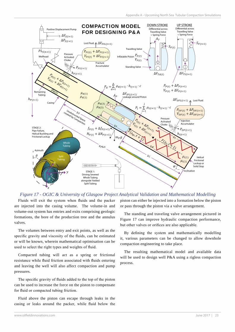
23June 2017 |
Appendix A - Upcoming North Sea Tubular Compaction Simulations
www.oilfieldinnovations.com
∆ ( +1) ∆ ( +1)
( +1)
(1) (2)
(1)
(1)
(2)
(1)
= ∑ ( +1) ∙ ℎ( +1) ∙=1
= ∑ ( +1) ∙ ℎ( +1) ∙=1
( ) + ∆( +1)
( ) + ∆( +1)
( ) + ∆( +1)
( ) + ∆( +1)
( ) ( +1)
( ) ( )
( ) + ∆ ( +1)
( ) + ∆ ( +1) ∆ ( +1)
( ) + ∆ ( +1)
( ) + ∆ ( +1)
(, + 1) ( , + 1)
&
ℎ ( +1)
ℎ ( +1)
( +1)
( ) + ∆ ( +1)
( +1)
( ) + ∆ ( +1)
∆ ( ) ∆ ( +1)
∆ ( +1)
∆ ( +1)
( ) + ∆ ( +1)
( ) + ∆ ( +1)
ℎ ( +1)
(3)(3)
In�atable Piston
Travelling Valve
Standing Valve
UP STROKEDOWN STROKE
PressureActivatedChoke
Positive Displacement Pump
Fracture Accumulator
SplitTubing
WholeTubing
InjectionAccumulator
PressureActivatedChoke
RemainingTubing
Casing
Unobstructed Space
created by Compaction
Leakage around Piston
Di�erential across Travelling Valve< Spring Force
Azimuth
Inclination
COMPACTION MODELFOR DESIGNING P&A
STAGE 2:Pipe Failure,Helical Buckling andFrictional Lockup
STAGE 1:Driving Severed
Whole Tubingalongside Yielded
Split Tubing
HelicalFrictional
Lockup orSolid Stop
Wellhead
Di�erential acrossTravelling Valve> Spring Force
Lost Fluid
Lost Fluid
Figure 17 - OGIC & University of Glasgow Project Analytical Validation and Mathematical Modelling Fluids will exit the system when fluids and the packer are injected into the casing volume. The volume-in and volume-out system has entries and exits comprising geologic formations, the bore of the production tree and the annulus valves.
The volumes between entry and exit points, as well as the specific gravity and viscosity of the fluids, can be estimated or will be known, wherein mathematical optimisation can be used to select the right types and weights of fluid.
Compacted tubing will act as a spring or frictional resistance while fluid friction associated with fluids entering and leaving the well will also affect compaction and pump pressures.
The specific gravity of fluids added to the top of the piston can be used to increase the force on the piston to compensate for fluid or compacted tubing friction.
Fluid above the piston can escape through leaks in the casing or leaks around the packer, while fluid below the
piston can either be injected into a formation below the piston or pass through the piston via a valve arrangement.
The standing and traveling valve arrangement pictured in Figure 17 can improve hydraulic compaction performance, but other valves or orifices are also applicable.
By defining the system and mathematically modelling it, various parameters can be changed to allow downhole compaction engineering to take place.
The resulting mathematical model and available data will be used to design well P&A using a rigless compaction process.

24 June 2018 | www.oilfieldinnovations.com
APPENDIX B - Answers to Common Questions and Concerns
This page intentionally left blank

25June 2017 |
APPENDIX B- Answers to Common Questions and Concerns
www.oilfieldinnovations.com
Answers to CommonTechnical Questions and Concerns
APPENDIX B
Common Concerns and Questions
Oilfield Innovations have proven the concept20 by compact-ing 2 3/8” tubing within 5 ½” API casing, as shown in Figure 13. The most common remaining questions and concerns are:
• How can Rigless Replace a Rig?
• What is Special about a Rig?
• How is Rigless Equipment Different?
• What does Thru-Tubing Mean?
• What does Wireline Look Like?
• What does Coiled Tubing Look Like?
• Above Seabed Equipment Removal?
• Does your Method work with Control Lines?
• How Much do you need to Compact?
• What about Helical Buckling?
• What about the Couplings?
• Oilfield Steel is too Strong!
• What about Integrity and Pressure Deration?
• Can you apply Sufficient Force?
• What about Different Tubing and Casing Sizes?
• Vertical Cutting Tools don’t exist!
• Retrieval and Re-Entering Previous Cuts?
• You’d need a lot of Expensive Tooling!
• How does a Vertical Cutter Work?
• How does a Packer Enter the Casing?
• What about Packer Element Damage?
• How do you Clean the Casing?
• What about Piston or Casing Leakage?
• How about Hydraulic Piston Lock-up?
• What about Repairs Requiring Casing Milling?
• How about Cutting & Pulling Casing?
• Compare your P&A Method to Rig P&A!
• What about 500 Foot P&A Plugs?
• Upside Potential for your P&A Method?
• How Protected are your Patents?
• How can your other Patents Help?
• What is Abrasive Filament Cutting?
• How does a Wireline Fluid Motor Help?
• Patents for Thru-Tubing Logging? and
• Logging After Placing a P&A plug?
• Compare your method with Thermite P&A.
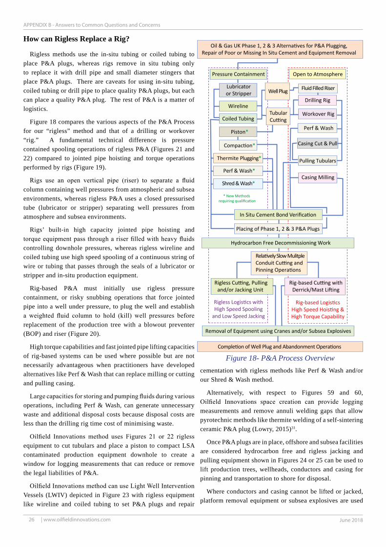
26 June 2018 | www.oilfieldinnovations.com
APPENDIX B - Answers to Common Questions and Concerns
Drilling Rig
Coiled Tubing
Removal of Equipment using Cranes and/or Subsea Explosives
Hydrocarbon Free Decommissioning Work
Wireline
Rigless Cutting, Pullingand/or Jacking Unit
Rig-based Cutting withDerrick/Mast Lifting
Pressure Containment
Oil & Gas UK Phase 1, 2 & 3 Alternatives for P&A Plugging,Repair of Poor or Missing In Situ Cement and Equipment Removal
Open to Atmosphere
Workover Rig
Rigless Logistics withHigh Speed Spooling
and Low Speed Jacking
Placing of Phase 1, 2 & 3 P&A Plugs
Completion of Well Plug and Abandonment Operations
In Situ Cement Bond Verification
Tubular
Well Plug
Relatively Slow MulitpleConduit Cutting andPinning Operations
Cutting
Lubricatoror Stripper
Pulling Tubulars
Piston*
Compaction*
Casing Milling
Casing Cut & Pull
Shred & Wash*
Thermite Plugging*
Perf & Wash*
Perf & Wash
Fluid Filled Riser
Rig-based LogisticsHigh Speed Hoisting &High Torque Capability
* New Methods requiring qualification
Figure 18- P&A Process Overview
How can Rigless Replace a Rig?
Rigless methods use the in-situ tubing or coiled tubing to place P&A plugs, whereas rigs remove in situ tubing only to replace it with drill pipe and small diameter stingers that place P&A plugs. There are caveats for using in-situ tubing, coiled tubing or drill pipe to place quality P&A plugs, but each can place a quality P&A plug. The rest of P&A is a matter of logistics.
Figure 18 compares the various aspects of the P&A Process for our “rigless” method and that of a drilling or workover “rig.” A fundamental technical difference is pressure contained spooling operations of rigless P&A (Figures 21 and 22) compared to jointed pipe hoisting and torque operations performed by rigs (Figure 19).
Rigs use an open vertical pipe (riser) to separate a fluid column containing well pressures from atmospheric and subsea environments, whereas rigless P&A uses a closed pressurised tube (lubricator or stripper) separating well pressures from atmosphere and subsea environments.
Rigs’ built-in high capacity jointed pipe hoisting and torque equipment pass through a riser filled with heavy fluids controlling downhole pressures, whereas rigless wireline and coiled tubing use high speed spooling of a continuous string of wire or tubing that passes through the seals of a lubricator or stripper and in-situ production equipment.
Rig-based P&A must initially use rigless pressure containment, or risky snubbing operations that force jointed pipe into a well under pressure, to plug the well and establish a weighted fluid column to hold (kill) well pressures before replacement of the production tree with a blowout preventer (BOP) and riser (Figure 20).
High torque capabilities and fast jointed pipe lifting capacities of rig-based systems can be used where possible but are not necessarily advantageous when practitioners have developed alternatives like Perf & Wash that can replace milling or cutting and pulling casing.
Large capacities for storing and pumping fluids during various operations, including Perf & Wash, can generate unnecessary waste and additional disposal costs because disposal costs are less than the drilling rig time cost of minimising waste.
Oilfield Innovations method uses Figures 21 or 22 rigless equipment to cut tubulars and place a piston to compact LSA contaminated production equipment downhole to create a window for logging measurements that can reduce or remove the legal liabilities of P&A.
Oilfield Innovations method can use Light Well Intervention Vessels (LWIV) depicted in Figure 23 with rigless equipment like wireline and coiled tubing to set P&A plugs and repair
cementation with rigless methods like Perf & Wash and/or our Shred & Wash method.
Alternatively, with respect to Figures 59 and 60, Oilfield Innovations space creation can provide logging measurements and remove annuli welding gaps that allow pyrotechnic methods like thermite welding of a self-sintering ceramic P&A plug (Lowry, 2015)31.
Once P&A plugs are in place, offshore and subsea facilities are considered hydrocarbon free and rigless jacking and pulling equipment shown in Figures 24 or 25 can be used to lift production trees, wellheads, conductors and casing for pinning and transportation to shore for disposal.
Where conductors and casing cannot be lifted or jacked, platform removal equipment or subsea explosives are used

27June 2017 |
APPENDIX B- Answers to Common Questions and Concerns
www.oilfieldinnovations.com
High Rotary Torque
VeryLarge
LiftingCapcity
withTall Derrick
orSubstantial
Mast
DISTINGUISHINGCHARACTERISTICS:
DRILLING RIGS
WORKOVER RIGS
OtherP&A Equipment
can beaccomodated
in variousways
HOISTING &TORQUEOPERATIONS
Figure 19- Unique Characteristics of Rig base P&A Equipment
Figure 20- Unique Characteristics of Rig based Well Control
to extract the conductors, regardless of whether a rig or rigless method is used.
Apart from high torque and high speed jointed tubular lifting, rigless equipment can perform any P&A task performed by a drilling or workover rig.
What is special about a Rig?
Drilling rig are designed for “drilling” and constructing wells. Large workover rigs are designed for working over wells to, for example, replace the tubing or “drill” smaller hole sizes when side-tracking a well. Large workover units are typically referred to as a rig, whereas small jacking and pulling units are generally referred to as rigless. The distinction can be confusing.
The real distinguishing characteristics of “rig” relative to “rigless” comprises large high-speed hoisting and torque capacity as illustrated in Figure 19.
Drilling rigs only use +/-25% of their equipment during P&A because time consuming and expensive torque operations like milling are avoided wherever possible while high speed lifting operations are less applicable to P&A than drilling.
Additionally, rigs perform work with the well open to atmosphere.
Rigs and special snubbing units can strip larger diameter pipe connections into a well by opening and closing blowout preventers around the tubular bodies as the string is pushed into a pressurized well, but the activity is one of the most dangerous in the industry and generally avoided.
As snubbing is universally avoided where possible, rigs also have the distinguishing characteristic of working with the well open to atmosphere and depending upon a weighted fluid column for control of well pressures.
While that is not necessarily a problem when constructing a well it can be troublesome during P&A because in situ equipment controlling well pressures must be removed as shown in Figure 20 and the stability of a weighted fluid column is often difficult to maintain during P&A.
An unstable weighted fluid column can be very expensive because all rig-based P&A work must stop until the well control fluid column is made stable.
Additional well control costs of maintaining a stable fluid column, above those necessary to replace the production tree with BOPs, are relatively common during rig-based P&A. It is relatively common to have a fluid influx when perforating casing during P&A because an expected pressure or fluid imbalance was encountered outside of the casing being perforated.

28 June 2018 | www.oilfieldinnovations.com
APPENDIX B - Answers to Common Questions and Concerns
MinimalisticWork Platform
Capable ofworking throughexistingproductionequipment
DISTINGUISHING CHARACTERISTICS:COILED TUBING
RIGLESS SPOOLING OPERATIONS
Spooling Support (Goose Neck)
Injector Headslides coiledtubing thru
pressurecontrol
equipment
ExistingWellhead
ExistingProduction
Tree
Coiled Tubingranging in size
from very small capillaryto large diameters
Tubing Reeland Winch
Available deck spaceon a Rig, Platform, Jack-up Barge
Light Well Intervention Vessel or Supply Boat.
Other P&A equipment requirements can be accomodated in various ways.
Figure 22- Unique Characteristics of Rigless Coiled Tubing
Pressurecontrol
equipment
Lubricator:pressurised
tube forholding
tools
Sheave
Electric orNon-Electric
Braided Wireline orSingle Strand (slick)
Wireline Winch
Load cell
Sheave
ExistingProduction
Tree
Wirelinevalve
Electric Line (braided wireline)or Slickline (single strand wireline)
Capable ofworking through
existingproductionequipment
DISTINGUISHING CHARACTERISTICS:RIGLESS SPOOLING OPERATIONS
Limited Workspace Required
Other P&A Equipment can beaccomodated in various ways
Figure 21- Unique Characteristics of RiglessWireline (single strand and braided cable)
How is Rigless Equipment Different?
Rigless well intervention equipment involves high speed spooling of a continuous string used in platform and subsea operations as shown in Figures 21 to 23. Rigless jacking and pulling units, shown in Figures 24 and 25, can jack or pull tubulars from a well after it has been plugged and, preferably, after the well is considered hydrocarbon free.
Figure 21 depicts wireline tooling using single strand (slickline) or braided-strand (cable) wire operations having non-electric bare wire or electrical core insulated wire. Gravity is used to deploy tools while wire is spooled from a winch through wheels and pulleys that measure distance and line pull until it reaches a stuffing box or grease head seal at the top of a lubricator (tube for holding tools). The lubricator is attached to blowout preventers which are attached to in-situ production equipment.
Figure 22 illustrates coiled tubing, which is like single strand wire (slickline) with the except a larger diameter and an internal passage for pumping fluids. The larger diameter of the coiled tubing requires an injector head push or pull the tubing within a well, whereby a stripper seal is used to prevent escape of well pressures as tools are spooled in and out of the well.

29June 2017 |
APPENDIX B- Answers to Common Questions and Concerns
www.oilfieldinnovations.com
Coiled tubing
Wireline or slickline
Controlumbilical
WellIntervention
Package
ROV umbilical
ROV tether
Guidelines
Coiled tubing,slickline or
wireline
Subsea wellhead
Subsea BOP
ROV
Figure 23- Rigless Light Well Intervention Vessel (LWIV) Equipment (Schlumberger)
Figure 25- Rigless Jacking Pulling Unit (JPU) Equipment (Canny, 2017)17
Figure 24- Rigless Jacking Frame (Franks Intl.)
Both Figure 21 wireline and Figure 22 coiled tubing can be used with a subsea lubricator attached to a subsea well from the Light Well Intervention Vessel depicted in Figure 23.
Jacking and Pulling Units (JPU) pictured in Figures 24 and 25 must be assembled on a platform to jack or pull tubulars using the platform as support. Light Well Intervention Vessels (LWIV) depicted in Figure 23 can use the buoyancy of the vessel to pull production trees, wellheads and severed casing from the seabed.
The combination of rigless equipment shown in Figures 21 to 25 have been used to perform many well plug and abandonments and, when combined with other decommissioning activities, can reduce the P&A cost by at least 32% (Siems, 2016)21.

30 June 2018 | www.oilfieldinnovations.com
APPENDIX B - Answers to Common Questions and Concerns
Surface Production Equipment
Rigless Equipment removesthis (swab) cap and worksfrom the top of the tree.
Hydraulic Actuator
Hydraulic Production Wing Valve
Production Tree
Wellhead
Tubing
ControlLinePort
Control LineControl Line
Control Line Port
Tubing Hanger
Productionoccurs fromthis flange
Kill Wing Valve
Hydraulic Master Valve
Manual Master ValveRig-based P&A removesProduction tree andand replaces it with afluid column and blowoutpreventers (BOPs)
A-Annulus Valves
A-Annulus Cap
B-Annulus Cap
C-Annulus Cap
B-Annulus Valve
C-Annulus Valve
Rigless methodscirculate betweentubing/casing and annulusvalves
Tubing
Production CasingIntermediate Casing
Surface CasingConductor Pipe
Phase 3 Well Abandonmentremoves this equipment fromjust below the seabed
Subsea wells basicallyhave the same equip.,albeit it is configuredfor underwater operationsand protected by a subea frame with the ability to interface through a subsearemote operated vehicle (ROV).
Figure 26 - In Situ Surface Production Equipment
What does Thru-Tubing Mean?
“Thru-tubing” indicates that small tools and a deployment string are passed through the production tree and tubing shown in Figure 26, whereas the tools of a “rig” are too large and must be deployed on pipe with enlarged connections that inhibit and effectively prevent fixed seals from isolating well pressures.
Except for small jacking and pulling units (Figures 24 and 25) rigless operations (Figures 21 to 23) work “thru-tubing,” i.e. through the smallest internal diameter of the tubing and associated completion jewelery, whereas rigs must remove the Figure 26 tree and replace it with a blowout preventer (Figure 20) prior to removing the tubing. The single exception is a horizontal subsea tree where the tubing can be pulled through the main valve block of the subsea tree.
Figures 27 and 28 illustrate how Figure 21 rigless wireline equipment is rigged up on top of the offshore platform production tree in Figure 26.
Figure 26 illustrates the internal components of a surface (dry) production tree and wellhead. Apart from B and C annuli access, subsea horizontal trees have the same basic components and flow paths. Subsea trees do not typically provide either B or C annulus access and cement from an inner casing string is not normally placed within the previous casing to prevent trapping fluids within annuli.
For both dry and wet (subsea) trees, access to the “A” annulus is typically sufficient to riglessly set the two primary P&A barrier plugs.
Rigless P&A can use the flow paths shown in Figure 26 to circulate fluids and cement into the well using the in-situ equipment and tubing.
Surface trees are relatively straight forward with access to all annuli, whereas working with subsea well equipment is more complex for both rigs and rigless operations.
The tubing is landed in “horizontal” subsea trees, whereas the tubing is landed in the wellhead below “vertical” subsea trees. Drilling rigs can pull the tubing through a horizontal subsea tree but must remove a vertical subsea tree to pull the tubing. The “A” annulus access in a “vertical” subsea tree passes through the tubing hanger, whereas “A” annulus access passes through a “horizontal” subsea tree’s primary valve block.
Differences in cement placement and annulus access cause differences in how P&A well control and cement placement is approached. With annulus access, cement can be circulated through in-situ tubing and annuli, whereas an inability to circulate through annuli dictates using rigless coiled tubing.
A rig and rigless subsea annulus is accessed using a remote
operated vehicle (ROV) to connection jumper hoses to the annulus, whereas the bore of subsea trees can be accessed by either floating drilling rigs or Light Well Intervention Vessels in deeper water depths, while shallower water depths require either jack-up drilling rigs cantilevered over the tree or an overboard jack-up barge crane supporting rigless subsea well

31June 2017 |
APPENDIX B- Answers to Common Questions and Concerns
www.oilfieldinnovations.com
Stu�ng Box(seal)
Lubricator(Tube)
for holdingtool string
Winch
Riser
ProductionTree
Wire
O�shorePlatform
Figure 28- Rigless Slickline and Wireline Equipment Rigged-Up on Small Platform
Figure 27- Rigless Slickline / Wireline Mast, BOPs and Lubricator Rig-up
control tooling attached to the subsea tree.
A primary P&A cement plug can be set through dry or wet production trees using a specialized wireline-set packer as a base and wiper plugs installed on a specialized spool piece to isolate the cement and indicate completion of the job (Olsen, 2017)105. This rigless operation is often performed on rig-based P&A prior to the Figure 20 removal of the Figure 26 production tree.

32 June 2018 | www.oilfieldinnovations.com
APPENDIX B - Answers to Common Questions and Concerns
Figure 29 - Slickline / Wireline Equipment (Wright, 2011)67
What does Wireline Look Like?
Most people have seen pictures of a drilling rig in the press or films23,24, whereas only practitioners can readily visualise wireline equipment shown in Figures 21, 27 to 29 and 42.
The photo of Figure 29 (Wright, 2011)67 looks downward upon wireline equipment (painted blue) placed on the deck of an offshore platform. The round shapes on the platform deck are access covers above each of the platform’s wells.
The Figure 29 control room wireline unit houses one or two people operating the wireline winch. The winch can use either single strand wire (slickline) or multi-strand wire (braided), wherein both types are referred to wireline. When electric conductance insulated wire is used with single or braided wire, electrified braided wire is referred to as “electric-line” or “e-line” while single strand mono core electric wire is referred to as “digital slickline (Loov, 2015)82.” Regardless of the type, wire passes across wheels and through pulleys that measure distance and line weight between the winch, mast and stuffing box or grease injection head as shown in Figure 21.
The difference between non-electric and electric wireline is primarily the pulling and jarring capacities of the wireline string. Immersing electrified wire into a liquid filled well requires isolation between fluids and electrical power that limits the pulling and jarring capacities lest the insulation become damaged.
Non-electric wireline rigless tooling can use battery powered tools together with hydrostatic pressure, shear pins and springs for actuation and deactivation, whereas digital slickline and e-line can actuate and deactivate tools real time via an electrical current passed through the wire.
A stuffing box is a stripper seal for smooth single strand wire (slickline), whereas a grease injection head is needed for sealing around the irregular curvature of braided wire.
Either a stuffing box or grease injection head will create a seal around the wireline at the top of the lubricator, which is just a pressure containment tube that holds small rigless tooling that can pass thru-tubing.
The lubricator can be connected to and disconnected from blowout preventers (BOPs) to load tools attached to the end of the wireline.

33June 2017 |
APPENDIX B- Answers to Common Questions and Concerns
www.oilfieldinnovations.com
Figure 30 - Rigless Coiled Tubing on Limited Space Small Platform (Sundramurthy, 2014)45
Figure 31 - Rigless Coiled Tubing on the deck of aDrilling Rig (Wright, 2011)67
The hydraulic unit powers the control unit and mast which is a portable crane used for lifting and lowering the lubricator to load and unload tools to and from the lubricator tube while BOP or valves of the well are closed. Once the lubricator loaded with tools and attached to the BOPs and pressure tested, the valves and BOP are opened to well pressure and the winch hoists tools into and out of the well using wire.
Wireline can be used with or without a rig and it is easy to see why wireline is the lowest cost rigless well P&A equipment when you compare its size in Figure 29 to that of the drilling rig in Figure 2.
What does Coiled Tubing Look Like?
Coiled tubing is slickline with a hole in it (Carl Lawson, Phillips 66). Figures 30 and 31 show coiled tubing equipment with small and large foot prints, while Figure 32 shows a close-up view of an injector head which differentiates coiled tubing from other rigless spooling equipment.
Coiled tubing comes in capillary sizes from ¼ inch (6.4mm) to ¾ inch (19mm) outside diameter, used primarily in downhole chemical treatments, and larger 1 inch (25.4mm) to 3 ½ inch (90mm) outside diameters for other applications.
Capillary coiled tubing provides an advantage over larger coiled tubing due to its lighter weight, smaller footprint, mobile structure, faster running speeds, and more economical costs, albeit friction pressures when pumping abrasive fluids can be limiting. Capillary tubing used for P&A in some remote onshore coal bed methane wells (Wilde92, 2013)92 can use Fly Ash Geopolymer Cements (Salehi, 2017)122 applicable to North Sea P&A.
Small coiled tubing equipment packages are comparable to more conventional larger spreads. A small coiled tubing package can be lightweight with a small-footprint which is especially beneficial where challenging crane or deck space limitations exist. The application of small coiled tubing units can substantially reduce costs, logistical support and risk exposure (Sundramurthy, 2014)45.
As shown in Figures 30 and 32, a reel can deploy coiled tubing through an injector head that pushes the continuous tubing through a stripper element that closes around the coil’s smooth outer surface to create a seal between well pressure and atmospheric or subsea environments.
Because rigs cannot work effectively through pressure containment, coiled tubing is often placed upon the deck of a drilling rig for well operations through the well’s in-situ production equipment, as shown in Figure 31.
A prime mover supplies power to the control system that hydraulically operates the reel (winch) that spools a continuous tubing string into and out of the injector head and stripper seal connected to in-situ production equipment. Coiled tubing tanks and pumps can circulate fluids through the coiled tubing when it is moving or stationary.
Oilfield Innovations’ method can use conventional coiled tubing P&A techniques for wells suffering from sustained casing pressure in one or more annuli. Abrasive jets can cut

34 June 2018 | www.oilfieldinnovations.com
APPENDIX B - Answers to Common Questions and Concerns
Figure 32- Coiled Tubing Injector Head on a Platform
holes into casing(s) across a full circumference of the casing, i.e. 360 degrees. An assembly can then be run on coiled tubing and rotated using an indexing tool followed by retainer plugs and squeezing of sealant behind the casing to stop the sustained casing pressures (Zwanenburg94, 2012; Tanoto109, 2017).
Where LSA scale inhibits through tubing access, coiled tubing can drill a pilot hole and use a scale-removal tool that jets beads to remove scale and provide access (Birk, 2013)95.
Coiled tubing is particularly useful in Phase 1 and 2 P&A due to its: i) ability to carry out work in live wells with high wellhead pressures; ii) versatility to convey tools and fluids that are necessary to secure the well and prepare it for decommissioning; and iii) a compact footprint and minimal environmental impact as compared to a rig or a snubbing unit (Webb, 2014)93.
Rigless coiled tubing equipment can be used from a platform’s or a rig’s deck, as shown in Figures 30 to 32, or it can be spooled from the deck of a jack-up barge to a platform which lacks sufficient space or to a subsea well in shallow water with a jack-up barge overboard crane supporting well control equipment.
Wireline and coiled tubing are regularly deployed from Light Well Intervention Vessels to access subsea wells in deeper water (Aguilar46, 2009; Willis75, 2013; Moeinikia63, 2014; Locken82, 2015; Gajdos51, 2015).
Small capillary coiled tubing, using fly ash polymer cements, or larger coiled tubing units, using normal cement or other sealants, can perform P&A in very limited platform spaces or larger spaces associated with platforms, barges or boats.
Oilfield Innovations’ method minimizes total P&A cost by first evaluating lower cost slickline or wireline with circulation through in-situ tubing. If circulating through in-situ tubing is not desirable, rigless small capillary diameter or more conventional diameter coiled tubing is used for P&A, wherein coiled tubing is substantially less expensive than rig-based P&A and still capable of providing a 30% to 60% P&A cost savings.

35June 2017 |
APPENDIX B- Answers to Common Questions and Concerns
www.oilfieldinnovations.com
Figure 33- Horne Wren Cond. Removal (Claxton)
Figure 34- Drilling Well Conductor for Pinning(Phillips UK Ltd,2001)96
Figure 35- Pinned Well Conductor and Casing(Phillips UK Ltd,2001)96
Above Seabed Equipment Removal?
Figure 33 depicts the removal of a conductor from the UK SNS Horne Wren platform using a crane and the jack-up barge in Figure 4. Figures 34 and 35 illustrate drilling and pinning of the Maureen Platform conductors and casings after they were cut with abrasive jetting (Phillips UK Ltd, 2001)96.
Jacking and pulling units of Figures 10, 24 and 25 are not always necessary and conductors and casing can be removed with a crane, as shown in Figure 33.
Figures 34 to 35 pictures show that the cutting, pulling and pinning of conductors and casing can be a time-consuming task where avoiding the high hourly cost of a drilling rig is the most economic option.
Rigs can cut and pull casings and conductors one-at-a-time assuming they are not stuck in place by cement or debris or, alternatively, wait for rigless abrasive cutting of multiple conductors with subsequent drilling (Figure 34) and pinning (Figure 35); however, both options are expensive.
Regardless of whether rig or rigless means are used, it is often the case that various well conductors and casing cannot be pulled with either jacking or drilling rig lifting and must wait for platform removal equipment as was the case for some wells during Maureen decommissioning46.
Accordingly, the removal of above seabed equipment is more economic when combined with other platform and subsea decommissioning activities.

36 June 2018 | www.oilfieldinnovations.com
APPENDIX B - Answers to Common Questions and Concerns
BARRIER
FLUIDPRESSURE:SEAWATEROR SALTBRINE ORHEAVY MUD
PRODUCTIONPACKER:OPTIONALLYCUT & PUSHEDDOWNHOLE
COMPACTEDTUBING &
CABLES
THRU TUBINGINFLATABLEPACKER PISTON30 ft (9m)
THRU-TUBINGLOGGINGWINDOW100 ft (30m)
RIG-EQUIVALENTWINDOW
EXISTING WELLHEAD
VERTICALLY SPLIT115 ft (35m) Split/Weakened115 (35m) Whole Spear
OFF-THE-SHELFTHRU TUBING
PROVENSLICKLINE,WIRELINE &
COILED TUBINGTOOLING
CEMENT100 ft
to 500 ft
CEMENT BARRIER
BARRIER
TUBING,CLAMPS &
CABLES
SCSSSV SCSSSV
SCSS
SV
PHASE 1RESERVOIR
ABANDONMENT
PHASE 2INTERMEDIATE
ABANDONMENT
PHASE 3ENVIRON
PLUG
A
B
C
D
E
F
G
H J
K
Figure 36- Compacting downhole Chemical Injection, Control Lines, Clamps and other Jewellery Downhole
Does your Method work with Control Lines?
Control and chemical lines are small, +/- ¼ inch (6.4mm) diameter, continuous capillary tubing or electrical cables attached to the tubing with clamps.
Various proven (TRL-7) knife and chemical cutters are capable of severing both tubing and associated small diameter lines clamped to the tubing’s outer diameter.
Control and chemical lines can be cut with conventional knife cutters and compacted to remove them from consideration as shown in Figure 36, wherein a Rig-Equivalent-Window will provide the required length of good cement. Where a plug longer than the compaction window is desired, experiments by Aas25, et al., show that embedding the control lines within the plug do not necessarily create a leak path. Also, fly ash geopolymer cement (Salehi, 2017)122, which can be pumped through capillary coiled tubing, can enter open control lines.
If the compacted volume of control and/or chemical lines and associated clamps are a concern, additional tubing can be compacted to account for the additional debris.
Other completion jewelery, including the surface controlled subsurface safety valve (SCSSSV) can also be pushed into a well’s lower end liquid spaces to provide an unobstructed logging and cementing space as shown Figure 36.
How Much do you need to Compact?
Good practice recommends logging at least 100 feet (30m) of in situ cement and, thus, a 100-foot (30m) logging window is needed.
Considering a compaction ratio of 50% and a 30-foot-long inflatable compaction piston, about 230 feet (100/0.5 +30), or 70 metres, of tubing would need to be compacted for each 100-ft logging window.

37June 2017 |
APPENDIX B- Answers to Common Questions and Concerns
www.oilfieldinnovations.com
Figure 37- Vertically Slicing Every-Other Tubing Joint
A 100-foot (30m) logging window can be formed by compacting an effective length of 115 feet (35m) of tubing spears into the 80%-90% liquid space around 115 feet (35m) of vertically split and weakened tubing.
For range 2 pipe, with an average length of 30 feet, 230 feet (70 m) of tubing is about eight (8) joints, wherein four (4) of the joints would be split and weakened with the other four (4) whole tubing joints used as spears. Range 3 pipe, with an average length of 41 feet, would result in three (3) joints being split and weakened with the other three (3) whole joints used as spears.
If clamps and control line debris is significant, an additional 30 feet (9m) could be added for such debris.
The math is simple and achieving a 50% compaction ration is visually evident in Figure 37. Finding 230 to 260 feet (70m-79m) of tubing adjacent to a formation with cap rock qualities within wells measured in thousands of feet or metres is normal practice within all P&A work scopes.
What about Helical Buckling?
Pipe-in-pipe arrangements with tubular movement within casing is peculiar to subterranean wells and often contributes to misconceptions regarding the strength of oilfield steel.
Tubular buckling research (Wu40, 1993; McCann42, 1994; Hishida41, 1996; Zdvizhkov39, 2005, Michell35-38, 1986-2006) demonstrates that helically buckling of pipe-in-pipe arrangements can exert very high frictional forces that can inhibit compaction of “whole” tubulars within other tubulars.
When whole tubing fails under axially compressive loads within casing, the failure tends to occur over a short axial distance because the friction of helically coiled and buckled tubing against the casing wall dissipates forces that might otherwise cause larger failures.
Buckling resistance is derived from a tubular’s diameter, cross sectional area, second moment of the area (bending) and polar moment (torsion).
Splitting the tubing in step #1 of Figure 12, as shown in Figures 11 and 14, destroys the strength of its circular shape to substantially reduce area and polar bending moment
resistance to facilitate bending shown in Figure 37 and allow side-by-side tubing compaction to achieve 50% compression.
What about the Couplings?
Unless downhole plasma cutting (Gajdos, 2015)51 is qualified for vertical splitting, cutting through both the tubular body and coupling will be difficult due to the thickness of the combined wall and coupling. Development of a downhole plasma cutter is an alternative to developing the mechanical vertical cutter of Figure 44, albeit downhole plasma cutting is likely to have higher development and operating costs.
Vertical splitting of the tubing body, using Figure 44 tooling, can cut the threaded portion of the body such that the body will separate from the coupling during compaction.
Using thru-tubing casing collar locator (CCL) logging, the in-situ depth of tubular couplings can be determined and either Figure 38 or Figure 44 tooling can be hoisted between the couplings to vertically weaken or slice every other tubular joint to provide Figure 37 compaction.

38 June 2018 | www.oilfieldinnovations.com
APPENDIX B - Answers to Common Questions and Concerns
Figure 38- Gator Perforator® (Source: Website)
Figure 39- API 5CT Steel Specification
Yield Strength
Stress
Ultimate Strength
Strain Hardening Necking
Strain
Fracture
Yield and Ultimate Strength
YIELD YIELD ULTIMATEMINUMUM MAXIMUM MINIMUM
PSI PSI PSIJ-55 55,000 80,000 75,000 K-55 55,000 80,000 95,000 C-75 75,000 90,000 95,000 N-80 80,000 110,000 100,000 L-80 80,000 95,000 95,000 HC-85 85,000 100,000 95,000 C-90 90,000 105,000 100,000 C-95 95,000 110,000 105,000 HC-95 95,000 125,000 110,000 P-105 105,000 135,000 120,000 P-110 110,000 140,000 125,000 Q-125 125,000 150,000 135,000
API 5CT - YIELDS
Accordingly, by vertically slicing every-other tubular body, the tubular string can separate at each coupling and a whole tubular joint can push its lower end coupling to bend and pass by the split tubular body as shown in Figure 37.
Flaring or bending of a split and weakened tubular body either inward or outward facilitates passage of the coupling as shown in Figure 11 and Figure 37.
As described in Appendix A, Oilfield Innovations are presently working with OGTC, OGIC and the University of Glasgow to better understand how to best split and/or weaken the tubular bodies to minimise compaction friction associated with the couplings.
Oilfield Steel is too Strong!
Believing that oilfield steels are somehow stronger than other steels is a common misconception. The yield strengths of other steels are similar. Oilfield tubulars generally have a greater wall thickness that provides additional strength, but splitting tubulars reduces the required bending force dramatically.
Figure 38 shows a Gator Perforator® tool visually demonstrates that oilfield steel is not as strong as you might believe, wherein it can rupture tubulars by “pushing” sharpened spikes through the wall of tubing. Such a tool could be used to weaken tubing if Oilfield Innovations cannot find funding to develop the tooling in Figure 44.
Like the lower part of Figure 13, the upper part of Figure 39 shows the relationship of stress, strain and yield strengths, while the lower table lists the yield strength minimum and maximum values as well as the ultimate yield values for various API 5CT specification tubulars.
As shown in the table of Figure 40, forces applicable to a compaction piston will far exceed the yield of oilfield steel once it is cut and/or weakened.
Yielding cut and weakened tubing is not a possibility; given sufficient force, it is a certainty.
What about Integrity and Pressure Deration?
The integrity of old wells is a concern for continuing production but not necessarily P&A.
Firstly, wells with higher grades of steel will have higher pressure ratings and, thus, compaction pressures will be matched to the steel grades being compacted even when the well pressure ratings have been derated.
Secondly, as shown in the table of Figure 40, the required pressures are not necessarily onerous and heavy fluids can be used to lower necessary surface pressures during compaction within derated pressure envelopes.

39June 2017 |
APPENDIX B- Answers to Common Questions and Concerns
www.oilfieldinnovations.com
Figure 40 - Applicable Piston and Fluid Weight Forces
Surface Pressure (psi) 0 1000 2000 3000 4000 5000 6000Depth TVD (feet) 6000 6000 6000 6000 6000 6000 6000
Casing Size Fluid7" (6" ID) Seawater - 28,274 56,549 84,823 113,097 141,372 169,646 9 5/8" (8.5" ID) Seawater - 56,745 113,490 170,235 226,980 283,725 340,470 13 3/8" (12.25" ID) Seawater - 117,859 235,718 353,576 471,435 589,294 707,153 7" (6" ID) 10-ppg NaCL Brine 12,350 40,625 68,899 97,173 125,448 153,722 181,996 9 5/8" (8.5" ID) 10-ppg NaCL Brine 24,786 81,531 138,276 195,021 251,766 308,511 365,256 13 3/8" (12.25" ID) 10-ppg NaCL Brine 51,481 169,340 287,198 405,057 522,916 640,775 758,634 7" (6" ID) 11.6-ppg CaCL2 Brine 26,465 54,739 83,013 111,288 139,562 167,836 196,111 9 5/8" (8.5" ID) 11.6-ppg CaCL2 Brine 53,113 109,858 166,603 223,348 280,093 336,838 393,583 13 3/8" (12.25" ID) 11.6-ppg CaCL2 Brine 110,316 228,175 346,033 463,892 581,751 699,610 817,469 7" (6" ID) 14-ppg WBM 47,637 75,911 104,185 132,460 160,734 189,008 217,283 9 5/8" (8.5" ID) 14-ppg WBM 95,604 152,349 209,094 265,839 322,584 379,329 436,074 13 3/8" (12.25" ID) 14-ppg WBM 198,569 316,427 434,286 552,145 670,004 787,863 905,721
Pounds of Force Against Compaction Piston
Finally, many old wells have leaking valves and seals that may need to be repaired or supplemented by, for example, pumping sealants into various voids and adding working valves to outside of valves which no longer work. Such costs are not necessarily significant.
It is important to remember that the objective of P&A is to “kill the patient” and not save it.
Integrity issues can be addressed at a relatively low cost for the remaining short life expectancy of the well, i.e. through P&A.
Can you apply Sufficient Force?
A geologic overburden normally has a water gradient which is assumed in the Figure 40 table of forces that can be applied to cut and weakened oilfield tubulars according to the piston’s casing size, applied surface pressure and fluids within the well at a depth of 6,000 feet (1829 metres), which is a relatively shallow fluid column weight applicable to most UK North Sea secondary P&A plugs. Deeper P&A compactions will have larger forces with weighted fluids and deeper fluid column heights while shallower depths may use still heavier fluids to compensate.
Figure 14 illustrates how tubing can be split and weakened. Cutting and weakening can be used to reduce the applicable steel area to less than one 1 in2 to more easily bend the walls of steel tubulars.
For arguments sake, assume the steel area resisting bending is 1 in2. Comparing the Figure 39 maximum yield (95,000 psi) for common North Sea steel (L80) to the table of Figure 40 demonstrates more than adequate bending forces are available.
About 2000-psi surface pressure applied to sea water at a depth of 6000 feet in 9 5/8” casing will overcome the maximum
yield of 1 in2 of L80 steel and, thus, allow tubing compaction. If 11.6-ppg brine is used then a surface pressure of 1000-psi is needed and if 14-ppg water based mud (WBM) is used then a surface pressure of a few hundred pounds per square inch is needed to overcome the maximum yield of 95,000 psi for 1 in2 of L80 steel.
The math is simple, oilfield steel has defined properties, cutting tubulars reduces the steel area applicable to bending and the forces available to compaction are more than sufficient to yield oilfield steel.
What about Different Tubing and Casing Sizes?
Figure 40 provides applicable compaction forces for different casing sizes, wherein North Sea casing sizes provide excellent compaction force. The proportions of tubular combinations are standardised (see Figure 11) and even 9 5/8 casing could be compacted into 87% liquid space within 13 3/8 casing when split using the Figure 44 tooling and severed using an abrasive filament cutter (see Figure 54).
Oilfield Innovations have proved the concept (see Figure 13) under the worst friction and piston force conditions. Our simulations used dry friction in a horizontal orientation, whereas North Sea wells will be fluid filled and vertical or inclined with significantly less friction. Also, gravity will add the weight of the steel to place the maximum force as the bottom to further maximise compaction.
North Sea 7 inch 29-ppf, 9 5/8 inch 53.5-ppf and 13 3/8 inch 72-ppf casings have 167%, 319% and 667% larger piston area sizes, respectively, than the 5 ½” 20-ppf casing used in our proof of concept, while L80 and P110 grades used in the North Sea have maximum yields only 119% and 175% greater than the J55 tubing used in our proof of concept. Compared to our proof of concept, the increase in piston force is greater than the increased strength of 1 in2 of steel.

40 June 2018 | www.oilfieldinnovations.com
APPENDIX B - Answers to Common Questions and Concerns
Figure 41- Downhole Cutting Wheel Performance (Campbell, 2009)130
Cutting Torque2-3/8 J-55 4.6#
0%
20 %
40 %
60 %
80 %
100 %
0 2 4 6 8 10
Cut Time (Minutes)
Avg
.Cut
ting
Torq
ue(N
orm
aliz
ed)
Size (in.)
Weight (lb/ft)
YieldStrength
(kpsi)
Approx. Cut Time(min)
2 3/8 4.6 55 10
2 3/8 4.6 110 25
2 7/8 6.5 80 25
2 7/8 7.9 110 60
More than enough liquid space exists within the casing and defined properties of API 5CT tubulars are exceeded by applicable piston forces shown in the table of Figure 40.
Vertical Cutting Tools don’t exist!
The proven Gator Perforator® shown in Figure 38 may be used to weaken tubing sufficiently that it could split along perforations to effectively shred tubing vertically.
Because the Gator Perforator® is not able to create a single split in tubing and cannot reach casing to enable casing compaction or Shred & Wash cement repair, Oilfield Innovations believe the tooling of Figure 44 should be developed, wherein Figure 41 proven cutting wheels technology is hoisted with the tooling of Figure 42.
Following OGTC and OGIC simulations described in Appendix A, Oilfield Innovations require support to develop a method of deploying proven tubular cutting wheels shown in Figure 44 or qualification of the Gator Perforator® with Figure 42 conventional wireline equipment.
As shown in Figure 41, cutting wheel experiments (Campbell, 2009)130 for J55 through P110 grade steel for 2 3/8 inch and 2 7/8 inch tubulars found that the average required force is relatively constant and cutting times vary according to the steel grade and wall thickness.
Oilfield Innovations have also proven the concept of cutting 5 ½” 20-ppf L80 tubulars with similar low cost cutting wheels available off-the-shelf from ordinary hardware stores. We severed a 5 ½ inch 20-ppf L80 tubular joint, “by hand,” with a conventional plumber’s cutting tool in about 300 rotations with no measurable wear to the cutting wheel.
Cutting wheels like that of Figure 41 can be very low cost and the required deployment tooling is limited to a few hand sized tools using mechanisms like the Figure 43 gauge hanger. Both cutting wheels and the gauge hanger deployment mechanisms are proven. Oilfield Innovations simply want to qualify the combination of these two proven technologies.
Retrieval and Re-Entering Previous Cuts?
If for any reason the tools are pulled, they can be rerun to re-enter previous cuts. For example, if operations are to be stopped due to daylight hours, incoming weather or should the Figure 41 cutting wheels dull and additional cutting is required, the wheels can be replaced and/or the tool rerun later.
The left of Figure 14 depicts gravity orientation of the tool body deploying a cutter skate for splitting and weakening tubulars. Gravity orients one or more aligned skates upward to the same groove each time it is run.
The right of Figure 14 illustrates that phasing of the cutters creates a stacked helical arrangement of cutting skates, wherein gravity acting on the unsupported parts of the tooling naturally urges the skates in a helical path when moved along the axis of the well and hoisted up or down.
If for any reason the tooling is pulled to surface before cutting through the tubular wall, when the tool is rerun gravity will orient the tool and naturally rotate it, as it is hoisted, until it falls into the previous cut grooves where the spring force on the skate cutters and sides of the grooves will hold it within the same cuts.

41June 2017 |
APPENDIX B- Answers to Common Questions and Concerns
www.oilfieldinnovations.com
SLICKLINE AND/OR WIRELINE UNIT
SLICKLINE AND/ORWIRELINE WINCH
DEPTHCOUNTER
LOAD CELL & SHEAVE
PRIMARY BARRIERSTUFFING BOX
SLICKLINE AND/ORWIRELINE SHEAVE
SECONDARY BARRIERSLICLINE/WIRELINE BOPs
PUMP-INTEE & VALVE
WORK VALVE
RISER
XMAS TREE SWAB VALVE CONNECTION
LUBRICATORWINCH
MAN-RIDINGWINCH
PORTABLEHYDRAULIC
EXTENDABLEMAST THIS EQUIPMENT
IS COMMONLY USEDON ALL WELLS
AND DRILLING RIGS
Figure 42- Rigless Mobile Single Strand (Slickline) and Braided Strand (Wireline) Equipment

42 June 2018 | www.oilfieldinnovations.com
APPENDIX B - Answers to Common Questions and Concerns
Figure 43GaugeHanger
(Interwellwebsite)
ConventionalGauge Hanger
Tool
You’d need a lot of Expensive Tooling!
As shown by the soft-drink-can-scale in the lower left of Figure 44, the tooling is relatively small with a 2.36-inch (60mm) diameter and can be combined with proven tooling that already exists for rigless wire and coiled tubing deployment.
To minimise development and ultimately operating costs, Oilfield Innovations have designed a single small diameter tooling set applicable for vertically cutting API specified OCTG tubulars from 3 ½” inch (88.9 mm) tubing to 9 5/8 inch (244.5 mm) casing and use proven mechanisms like cutting wheels and gauge hanger skate deployment.
While nothing in the oilfield is cheap, our tooling will be at the bottom of oilfield tool development cost rankings.
How does a Vertical Cutter Work?
The Figure 41 cutting wheels are deployed on skate’s body like the slips on the Figure 43 gauge hanger, whereby skates are extended then hoisted up and down by the Figure 42 wireline tools deployed through in situ production equipment.
The tools function like ice skates or roller skates with sharp edges that are pushed and pulled across ice or flooring to cut a groove and deepen the groove until the ice or flooring are completely cut.
We propose qualifying basic tools that use sliding shafts, springs and shear pins, which are the simplest and most reliable mechanisms in the oil and gas industry.
Alternatively, if funding is not found, we could qualify the Figure 38 Gator Perforator®.
Figure 44 illustrates a single vertical cutter tool string with a single skate cutter tool (07) deployed in three different positions A), B) and C). Figure 44 also depicts tool subassemblies (01) to (10).
Figure 44 has a single skate subassembly (07) carrying three cutting wheels usable to split and weaken the tubing in step#1 of Figure 12.
Multiple vertical skate cutters subassemblies (07) can also be stacked and either aligned or phased, as shown on the far left and right sides of Figure 14.
Figure 44 deployment position A), cutting position B) and retrieval position C) use proven TRL-7 subassemblies 01 to 05 while subassemblies
06 to 10 are new tools to be manufactured and qualified.
Funding is needed for the construction and qualification of new components comprising Figure 44: spring drive (06), vertical skate cutter (07 extended & 09 retracted), a telescopic spring release (08) and an adapter (10) for connecting to other tools.
Figure 44 position A) illustrates the cutter in a retracted position that is lowered into the well on wire attached to the rope socket (03). Tools are guided over any upsets within in situ production equipment using the roller stem (04) wheels and knuckle jar (01).
A hydrostatic actuator (02) is programmed to measure the hydrostatic pressure and temperature for actuation after a specified depth has been reached and a specified time has elapsed.
Figure 44 position B) illustrates firing of the first hydrostatic actuator (02) at the desired depth to cock a spring tool (06) that drives an internal shaft to apply a constant force that deploys and holds the skate’s cutting wheels against the tubular wall.
Engaging the skate cutting wheels against the tubular wall, then hoisting the skate up and down on a wire, cuts the tubular’s inner wall vertically until a second programmable hydrostatic actuator (02) fires.
The second actuator is used to shear pins in the telescopic tool (08) that releases the spring force (06) to allow the skate to retract into Figure 44 position C) for retrieval from the well.
Any qualified slickline tool manufacturer can design and construct such tooling using standard mechanisms and their experience with other tools like the Figure 43 gauge hanger.

43June 2017 |
APPENDIX B- Answers to Common Questions and Concerns
www.oilfieldinnovations.com
TOOL STRING WHILE RUNNING TO DEPTH
TOOL STRING WHILE VERTICALLYCUTTING (HOISTING UP AND DOWN)
TOOL STRING WHEN PULLED OUT-OF-WELL
TRL-7ROPESOCKET
TRL-7 KNUCKLEJAR
TRL-7ROLLERSTEM
TRL-7 HYDROSTATICPROGRAMMABLE
ACTUATOR
TRL-7TUBING ENDLOCATOR
TRL-1HYDROSTATIC
ACTUATEDSPRING
DRIVE
VERTICALCUTTER
TRL-1EXTENDED
TRL-1TELESCOPIC
RELEASE
TRL-1RETRACTED
VERTICALCUTTER
TRL-1HYDRAULIC
TRL-7CUTTINGWHEELS
ACUTATORADAPTER
Position A) Position B) Positon C)
01
02
03
04
05
06
07
08
09
10
Mar
que
dep.
SCALE
Figure 44 - Vertical Cutter Slickline Tool String in Running A), Cutting B) & Retrieval C) Positions

44 June 2018 | www.oilfieldinnovations.com
APPENDIX B - Answers to Common Questions and Concerns
#3 #3A #3B
InflatePackerinside
Tubingand
PressureTubing to
Extrudefrom
LowerEnd
Cross-Linked
PolymerFluid
ImprovesSeal
CleaningFluid
Tubingpushed
downand/orUpper
TubingLifted
ContinueInflatingPacker
as itexits
Tubing toEngageCasing
UpperTubing
Liftsand/or
BottomPushed
Down
Figure 45- Thru-Tubing Packer Inflation
How does a Packer enter the Casing?
Severing tubing that is in tension allows the severed end to fall and slump which may, or may not, provide sufficient space for inflating a packer within the casing. A wireline impression block and tubing end locator can be run to determine if sufficient slump has occurred.
If the tubing does not slump sufficiently, the packer can be inflated and deployed from inside the tubing as shown in Figure 45.
In such cases, step #3 of Figure 12 is extended to steps #3A and #3B of Figure 45, wherein the packer is partially inflated with tubing pressurization extruding the packer from the end of the tubing to cause the hanging tubing to lift off the piston and/or force the tubing spear downward.
During extrusion or after extrusion from the tubing, the packer will further expand to create a seal and form a piston in the casing.
Inflatable packers are like your car tyre. The pressure in your car tyre can be low and still support your car because the weight of your car compresses the tyre and, thus, increases the pressure in your tyre. Similarly, high inflatable pressure within the tubing may result in a lower inflatable pressure in the casing, but it will still expand to the casing as pressurised fluid above compresses and increases the inflatable element’s internal pressure to create sealing side force.
A cross-linked polymer fluid can also be placed above the inflatable to prevent leakages due to changes of diameter when expanding from the tubing to the casing.
Proven cross-linked polymers (Reddy, 2003)59 are regularly used to stop dire downhole fluid leakages and are very strong semi-fluid gels that are difficult to shear and, thus, can seal across relatively large gaps.
What about Packer Element Damage?
Conventional inflatable packers use slats attached to a robust elastomeric element, like your car tyre, whereby the slats protect the element and anchor the packer to the casing.
The inflatable manufacturer can attach smooth slats to inflatable elements to minimise friction and allow it to slide while protecting the inflatable elastomeric membrane during tubular compaction.
Alternatively, more rugged and lower cost packers can be designed and qualified. For example, a Kevlar (bullet proof)
bag can be filled with a particle sealant like Sandaband® (Sassen, 2011)114 to be extruded from the tubing, as shown in Figure 46, without damaging the bullet proof bag. Pleats in the Kevlar bag can allow particle sealants to fall while internal bow springs expand the pleated bullet proof bag as it transitions from tubing to casing.
Oilfield Innovations are recommending inflatable packers for compaction to minimise the cost of developing the new

45June 2017 |
APPENDIX B- Answers to Common Questions and Concerns
www.oilfieldinnovations.com
Figure 46- Managing Compaction Hydraulics
#4
Fluids can be Injected into a formationthrough a Planned Perforation
Fluids can be bleed from the bottomof the piston using beam pump valves
Leaks in the Casing or past the Pistoncan be managed with the pump ratesexceeding leakage rates and/or withviscous fluids and/or particles likecross-linked polymers or mud with LCM
Fluids can be Injected into a Depleted Reservoir
Spring
BeamPumpValves
Down StrokeAbove Piston Pressure
> Trapped Pressure+ Spring Force
Pump PressureCloses Springto Fill Chamber
and CloseStationary Valve
Spring LiftsTravelling Valve
as PressuresEqualize to
Fill Chamber
Up StrokeAbove Piston Pressure
< Trapped Pressure+ Spring Force
Alternatively, poppet or venturi valves
Source: (S. Fallahzadeh, 2017)50
00
1450 psi10 MPa
2900 psi20 MPa
-0.5
0.0
0.5
1.0
1000 2000
Frac
turin
g P
ress
ure
Pre
ssur
izat
ion
Rat
e (M
Pa/
s)
Wellbore Pressurization Rate
Fracture Break Down Pressure
Fluid Flow throughthe Fracture
Fracture Pressures
Filling WellboreEnd of Fracture
Propagation
Fracture
Initiation
Pressure
Time (s)
technology, but a low-cost Kevlar bag compaction piston could also be part of the development if there are concerns about damaging inflatable packers.
How do you Clean the Casing?
The piston packer contacts the casing. As it is hydraulically forced downhole, previously placed cleaning fluid and the metal slats attached to the elastomeric inflatable packer element or Kevlar bag can scrape and clean the casing walls to provide a water wettable surface for cement bonding.
Cleaning the casing during compaction also minimises waste fluids by keeping such fluids and debris downhole.
What about Piston or Casing Leakage?
Leakages above or around the compaction piston can be managed by adjusting the pump rate to exceed the leakage rate and/or with industry proven thixotropic fluids, polymers and/or brines or drilling mud with lost circulation material (LCM), as illustrated in Figures 45 and 46.
Many positive displacement surface pumps can supply sufficient pressure and volume to maintain compaction movement at a dynamic frictional value. If pump capacity exceeds that needed to keep the compaction moving, small seepage losses in the system are not necessarily an issue.
Cross-linked polymer fluids usable to plug leakages above or around the compaction piston can be time and temperature dependent as well as environmentally friendly (Reddy, 2003)59, wherein the high fluid friction of the cross-linked gels can effectively seal leakages during compaction.
Alternatively, LCM laden environmentally friendly brine or drilling mud can be used to both seal fluid loses at or above the compaction piston and supply additional specific gravity compaction force.
What about Hydraulic Piston Lock-up?
Pressure integrity above the piston maximises compaction force on the piston, whereas disposal or leakage below the piston is desirable to ensure that trapped fluid does not impede compaction.
Figure 46 describes various methods that can be used to avoid hydraulically locking the piston by trapping fluids below it. The alternatives include valves and injection into
the reservoir or another formation.
Low fluid friction injection into a depleted reservoir is relatively easy.
Perforating and fracturing a non-reservoir formation below the intended compaction depth can also be used to prevent trapping of fluids below the piston.

46 June 2018 | www.oilfieldinnovations.com
APPENDIX B - Answers to Common Questions and Concerns
Step #0 Step #3 Step #5 Step #5A Step #5B Step #6A
Hole
Casing
Coupling
Tubing
Coupling
SplitTubingat theCoupling
BridgePlug
In�atablePacker
(piston)
LoggingDiscovers
Poor orLacking
In SituCement
Compaction
CasingScrapping
CleaningViscous
Polymertimed todissolve
over timewith well
temperature
Low CostTRL-7
CuttingWheels
WirelineHoisted
Repeatedlyto Shred
Casing
As toolsis liftedup and
downcuttingwheels
shredcasing
CirculationaroundPacker
or AngledFluid Jet
Cleaning
ShreddedStrands
of CasingVibrate
RemovingEccentricity
FrictionalIssues
JettedCementVibrates
CasingStrands
CoiledTubing
EmbeddedCasing
StrandsStrengthen
Plug likeRebar
ShreddedCasing
Expandedto CloseAnnulus
Figure 47- Elevation View: Shred, Wash and Cement (SWC) Method of P&A Annular Cementing Higher pressure fracture breakdown can be initiated before placing the piston. As shown in Figure 46, fracture reopening back pressure of about 1200-psi, or 8-MPa (Chan110, 2015; Fallahzadeh50, 2017) will resist compaction. Heavier fluids can be used to negate or partially offset back pressure due to injection.
Alternatively, or in addition, trapped fluid and/or pressures below the injection pressure can be bleed-off through various valve arrangements through the centre of the piston comprising, for example, an orifice, a venturi, poppet valve or a combination of traveling and stationary valves like that depicted in Figure 46.
What about repairs requiring Casing Milling?
For various reasons squeeze cementing repairs can be necessary, even for a drilling rig, when milling is undesirable and/or when cutting and pulling partially cemented casing is practically impossible. Various rig and rigless cement squeeze repair methods are usable to repair in-situ cementation (Zwanenburg94, 2012, Teleghani58, 2016; Tanoto109, 2017).
When conventional squeeze cementing is insufficient and the casing cannot be cut and pulled, the remaining rig-based option is milling the casing to remove the poor cement and reach a virgin rock face.
Casing section milling is time consuming and exposes a rig’s blowout preventers to damaging metal fragments called swarf and, hence, casing section milling is avoided where possible even during drilling rig P&A. Accordingly, rig-based P&A proponents have developed improved methods of squeezing cement like Perforate, Wash and Cement (PWC) which is commonly referred to as Perf & Wash. A Perf & Wash method can avoid milling by perforating the casing, washing the annulus through the perforations and placing cement across the whole cross section of the wellbore (Delabroy27, 2017).
Perf & Wash can be used to remove the need for traditional rig-based casing milling (Ferg32, 2011; Denmon33, 2016; Delabroy27, 2017); however, Perf & Wash simply adds more perforations to conventional squeeze cementing practice to provide better circulation and, therefore, can also be used riglessly with coiled tubing (Moeinikia63, 2014; Skorpa115, 2016) to deliver a rigless work scope where multiple tubulars are embedded in cement.
Cleaning circulation through small perforations can require high flow rates and create large volumes of waste that may, in various instances, be unsuitable for rigless pumping and waste storage capacities.

47June 2017 |
APPENDIX B- Answers to Common Questions and Concerns
www.oilfieldinnovations.com
Microannuli Coiled TubingRotational
Jetting
P&A PlugReinforced by
Shredded CasingStrands
Shape ofShredded StrandCauses Vibration
Debris and/orFluid Friction
CementSqueeze
and Vibration
RemedialCement
Repair
POOR IN SITU CEMENTATION(SHRED & WASH)
REPAIRED CEMENTWITH P&A PLUG
Figure 48 - Plan View: Shred, Wash and Cement (SWC) Method of P&A Annular Cementing
Accordingly, Oilfield Innovations have patented a Shred & Wash method shown in Figure 47 that is better suited to rigless operations.
Rig-based proponents of Perf & Wash have performed full-scale experimental testing to demonstrate that good cement placement is possible when the tubulars are left within other tubulars in the hole, even when control lines are present. The experiments showed that cement can be well-placed within the in-situ tubing annulus, but some microannuli may be present, albeit they are probably not continuous (Aas, 2016)25.
Perf & Wash can be improved by shredding the tubular wall to eliminate cleaning and cementing through numerous small diameter perforations, wherein shredding also removes microannuli through vibration as depicted in Figures 47 and 48.
Figure 47 step #0 shows production tubing within uncemented casing. Step #3 of Figure 47 replaces step #3 of Figure 12 and depicts vertically slicing across a coupling to eliminate the need for severance.
Within step #5 of Figures 12 and 47, logging discovers that the in-situ cement is poor or lacking. Figure 47 step #5A then shreds the casing using tools similar in configuration to the right side of Figure 14.
Figure 47 step #5B illustrates washing and cleaning the shredded casing with a fluid inflatable packer element used to divert circulation through the shredded casing strand gaps.
Figure 47 step 6A uses coiled tubing cementing and replaces
step #6 of Figure 12, wherein the fluid inflatable packer of step #5B was further inflated to expand the shredded strands of casing and provide annulus support for the P&A plug.
Oilfield Innovations’ TRL-0 Shred & Wash method of Figures 47 and 48 can be proved and qualified with coiled tubing flow rates to reduce the need for rig-based P&A.
Shred & Wash can reduce required pump flow rates and waste generation through the vibration of shredded casing strands, which will also reinforce the P&A plug like rebar reinforces concrete.
As shown in Figure 47 and Figure 48, shredded casing strands can vibrate when fluid is jetted against their inner arc, wherein fluid diversion acts toward one side of the strands’ inner arc to induce twisting forces that can vibrate the strand to dislodge debris and embed the strand within cement.
Research that justifies numerous small perforation holes in casing equally indicates that the larger vertical cuts of Shred & Wash could provide a viable alternative to casing section milling for both platform and subsea wells.
Shred & Wash is an upside potential for the present tubing compaction support request or, alternatively, can be a part of a separate support request for rig-based and rigless P&A.
What about Cutting & Pulling Casing?
After pulling the tubing, in cases of uncemented casing-in-casing, a rig-based P&A typically cuts and pulls casing to provide the work scope shown on the left of Figures 5 and 49.

48 June 2018 | www.oilfieldinnovations.com
APPENDIX B - Answers to Common Questions and Concerns
Figure 49 - Simple schematic of abandoned wells (left: Moeinikia63, 2014; right: Varne85, 2017 )After
Rig-Basedwith cuttingand pullingof casing(Moeinikia)
Rigless SubseaWell P&A
with LWIV(Varne)
Figure 49 shows an elevation view for a rig-based P&A work scope on the left and an elevation view of a rigless P&A work scope for a subsea well on the right.
A rigless pulling and jacking units (PJU), pictured in Figures 24 and 25, can also cut and pull casing (Canny, 2017)17, just like a rig, only much slower.
Uncemented casing-in-casing arrangements are, by design, typically located significantly above producible hydrocarbon zones, but there may be overpressure water bearing zones or unproducible hydrocarbon layers around which P&A plugs should be located.
As earlier discussed, the legal liabilities of hydrocarbons and pressurized water zones are not the same. Probabilistic risk-based P&A approaches, proposed by Aas25, DNVGL and others, can be more acceptable for over-pressure water zones and insignificant unproducible hydrocarbon zones.
Also, work by various authors (Davies60, 2004; Marriott62, 2007; Gubanov61, 2014) shows that other methods like reverse cementing can also be used to improve the cementing of annuli of casing-in-casing arrangements to mitigate the need to cut and pull casing.
From a practical viewpoint, with respect to the right side of Figures 49 and 50, using a risk-based approach to justify not cutting and pulling casing to isolate a water bearing zone or unproducible hydrocarbon zones may provide acceptable legal liabilities because consequences are virtually non-existent. Water leakages into offshore strata and/or the ocean
cannot be measured and unproducible hydrocarbon layers have insufficient permeability to leak in any meaningful amounts.
For non-reservoir P&A plugs #3 and #4, a Rigless Pulling and Jacking Unit (PJU) can cut and pull casing or, given the extremely low to negligible risks of leakages from water zones or hydrocarbons trapped in impermeable rock, a risk assessment can be carried out for use of rigless Perf & Wash, Shred & Wash and/or Reverse Cementing methods that can be used to keep risks as-low-as-reasonably-practicable (ALARP), from a legal liability viewpoint, to provide the rigless work scope on the right side of Figure 50.
Compare your P&A Method to Rig P&A!
Figure 50 elevational cross-sectional schematic details the differences between rig and our rigless P&A for comparison with Figure 49 rig (Moeinikia, 2014)63 and conventional rigless P&A (Varne85, 2017)85.
During Phase 1 P&A, both rig and rigless work scopes use low cost wireline spooling equipment with a single strand of wire (slickline) or a braided wire cable, wherein either can be electrified (electric-line).
Wireline equipment is predominantly used in Phase 1 reservoir P&A. Some companies use wireline to set mechanical plugs to facilitate pulling the tubing with a rig (Shell6, 2017) while others use wireline crews to set multiple P&A cement plugs to isolate the reservoir (Plumb16, 2003).

49June 2017 |
APPENDIX B- Answers to Common Questions and Concerns
www.oilfieldinnovations.com
Figure 50 - Comparison of Rig-based to Rigless P&A with Logging Windows
VERIFIABLEIN SITU CEMENTPRIMARYP&A PLUG #1IsolatingReservoir
Production Casingwith LinerVarious Completions
exist below the Prod.Casing, but they havelittle effect on the P&A
Reservoir
Over PressuredWater Zone
Cap Rock
Intermediate Casing
Surface Casing
Conductor
Phase 3 P&APhase 2 P&A
Phase 1 P&APhase 2 P&A
B-AnnulusValves
C-AnnulusValves
A-AnnulusValves
A production treeis secured to the
top of the wellhead
ProductionPacker
500-ftCement &
100-ft (30m)LoggingWindow
100-ft (30m)LoggingWindow
VERIFIABLEIN SITU CEMENTSECONDARYP&A PLUG #2500-ft (152m)
+/- 230-ft (70m)of TubingCompacted
+/- 230-ft (70m)of TubingCompacted
100-ft (30m)Perf & Wash orShred & WashWindow
TERTIARYP&A PLUG #3500-ft (152m)
AbbrasiveSeverance
AbbrasiveSeverance
Before P&A Rigless P&Aw/ Logging Windows
Typical Rig-Based P&Aw/ Logging Windows
SCOPE OF WORK:Work through Tree,Set Plugs #1 to #3,Remove Tree,Abbrasive Cut,Plug #4,Abbrasive Cut,Remove Wellhead& Remaining Casing
EnvironmentalPlug #4
Alternatively,a Rigless Jacking
and Pulling Unit(see Figure 55,Canny, 2017)17
can be used toprovide rig-based
cut and pullingof casing
+/- 230-ft (70m)of Tubing
Compacted
+/- 230-ft (70m)of TubingCompacted
UNVERIFIABLEIN SITU CEMENT
P&A PLUG #1Conventional
Bullheadingof Cementto IsolateReservoir
FREQUENTIN SITU CEMENT
VERIFICATION:PRIMARY
P&A PLUG #2500-ft (152m)
ViscousFluid Base
for Plug
Cut and PullCasing, setMechanical
Plug
INFREQUENTIN SITU CEMENT
VERIFICATION:SECONDARYP&A PLUG #3500-ft (152m)
EnvironmentalPlug #4
SCOPE-OF-WORK:Plug #1,
Remove Tree,Rig-up BOP,
Plug #2,Rig-down BOP,Remove Spool,
Rig-up BOP,Plug #3,Plug #4,
Remove Wellhead& Remaining Casing
Cut and PullCasing
ViscousFluid Base
for Plug

50 June 2018 | www.oilfieldinnovations.com
APPENDIX B - Answers to Common Questions and Concerns
Figure 51 - Channelled Flow (Guo, 2014)64
For challenging rig and rigless P&A work scopes, coiled tubing can be used to perform reservoir and intermediate P&A in Phases 1 and 2 (Freeman12, 2015).
As shown in Figure 50, when isolating the reservoir in Phase 1, rig-based P&A normally leaves the production packer in place. Conventional rig and rigless P&A typically bullhead cement into the reservoir through in situ tubing (Olsen, 2017)105, whereas our compaction method can compact tubing below the production packer to verify in situ cement and place a primary P&A plug.
Once the well can be opened to atmosphere, rigs remove the tubing and associated production jewelery before logging in situ cement and placing a viscous fluid to support a primary P&A plug #2 as shown on the left of Figure 50. A rig will then cut and pull uncemented production casing before setting a mechanical plug to support a secondary P&A plug #3. For reasons of cost, rigs infrequently log in-situ cement for a secondary P&A plug. The intermediate casing will then be cut and pulled before setting an environmental plug and removing above seabed well equipment.
Alternatively, instead of cutting and pulling casing, a rig may use a Perf & Wash method (Ferg32, 2011; Abshire69, 2012; Khalifeh68, 2013; Moeinikia63, 2014; Aas25, 2016; Delabroy27, 2017) and, therefore, the method is equally applicable to lower cost rigless P&A.
Oilfield Innovations’ rigless method uses a piston to compact part of the tubing, and any associated jewelery, control or injection lines, to create at least a 100-ft (30m) logging windows before placing the 500-ft (152m) cement plugs through the remaining in situ tubing as depicted on the right of Figure 50.
Oilfield Innovations can use Perf & Wash, Shred & Wash and/or various techniques including Reverse Cementing methods (Davies60, 2004; Marriott62, 2007; Gubanov61, 2014; Vrålstad106,2016; Durmaz107, 2016; Rogers108, 2016; Tanoto109, 2017; Olsen105, 2017) for placement of P&A plugs #3 and #4 on the right of Figure 50.
Alternatively, rigless pulling and jacking units can cut and pull casing (Canny, 2017)17 to make the upper portion of the well P&A look like that of a rig-based P&A where necessary.
After rigless P&A plugging, the platform or subsea equipment above the mudline is hydrocarbon free and various rigless methods using abrasive cutting, explosives or other means are used to remove the above seabed equipment with jacks and cranes.
Accordingly, as shown in Figure 50, using various industry proven methods and equipment, Oilfield Innovations’ rigless method can deliver a rig-equivalent P&A using
rigless logistical means that can be combined with other decommissioning activities to reduce total P&A cost by 30% (Siems, 2016)21 to 60% (Varne, 2017)85.
What about 500 Foot P&A Plugs?
Both rig and rigless methods can place 500 feet (152 m) of cement and both require 100 feet (30 m) of confirmed in-situ cement bonding. Therefore, regardless of the cement plug height, a 100-foot (30 m) logging window is sufficient.
During rigless operations the end of the severed tubing hanging from the wellhead can be centralised above the 100-foot (30 m) window to better place a 500-foot P&A plug, wherein 400 feet of tubing would be embedded within the plug.
Cement within the 100-ft (30m) logging windows provides adequate compliance, but experiments (Aas, 2016)25 demonstrate that embedded tubing can provide sealing P&A plugs and placing 500-ft (152m) P&A plugs would be acceptable. Also, unlike the small diameter stingers used by drilling rigs, the constant diameter of the tubing can provide an uncontaminated balanced plug (Rove, 2014)29 making less than a 500-ft (152m) cement plug appropriate when using computer modelling to adjust pumping parameters (Guo, 2014)64 for channelling of heavy cement through lighter fluids, as shown in Figure 51, within the lower 100 feet (30m) window.
Accordingly, Oilfield Innovations’ rigless method can provide 500-foot cement plugs without unnecessary extra cutting and compacting by embedding in situ tubing above the logging window and using it to place a balanced cement plug consistent with industry practice.

51June 2017 |
APPENDIX B- Answers to Common Questions and Concerns
www.oilfieldinnovations.com
Key productpatents are filed
in Brazil
All of our patentsare filed in the USA
Key product patentsare filed in Mexico
Key product patentsare filed in Canada
Key UAE patentsare filed for protection
in the Middle East
Most of our productspatent are filed in the EU
To capitalise uponPatent Box Tax Benefits
all of our productsare patented in the UK,
which now providesfurther benefitgiven BREXIT
Key EU Patentshave been filedin Norway
Key productpatents are filed
in Australia
Key productpatents are
filed in Malaysia
Key productpatents are
filed in Indonesia
Most of ourproduct patents
are filed in China
We have limitedpatent filings in
Argentina
Key product patentsare filed in Russia
Patenting Strategy:Patents in countries
where large Operatorsor Service Companieshave Headquarters or
produce significantoil & gas volumes
PATENTSPATENTS
Figure 52 - Oilfield Innovations Worldwide Patents
Upside Potential for your Method?
Oilfield Innovations have a portfolio of patents relating to rigless P&A methods within the countries shown in Figure 52. This has taken many years and fully depleted our funding capacity.
We are willing to combine our P&A patents into a portfolio that can be marketed to pay for development of the various new technologies within the patents.
It is not the purpose of this document to demonstrate the viability of our additional patented technologies so we briefly explain the core principles on the following pages to allow the reader to see the upside potential that our patented methods can provide in the future. For those who are interested, Oilfield Innovations can provide more information.
How protected are your Patents?
We have ring fenced patents with other patents that provide a worldwide legal monopoly for the methods and equipment described herein. Breaking our ring-fence of patents would be extremely difficult regardless of available legal resources as inventions are not only broadly claimed but also intertwined and cross referenced.
For example, the patent described by Figure 53 describes the use of well abandonment to develop new technologies and further references the methods described herein.
Also, Figure 54 describes method and apparatus for using abrasive filament cutters that claim vertical cutting and cross cutting of vertically cut surfaces, which also references fluid motors run on wireline in Figure 55 that are claimed as part of our primary compaction method.
Finally, Figures 56 and 57 cement bond logging before and after P&A cement placement also references our patented method of tubular compaction.
The value of our patents is not just their simplicity and ability to provide step changes in the P&A costs, their value also relates to worldwide legal protection for enterprises that develop and distribute licenses for using the method in other countries.
If the patents are controlled by those wishing to profit from or drastically reduce the cost of P&A, the method can be licensed to local companies in other countries wishing to use the method.
If worldwide patents are controlled from an oil and gas technology centre or city, the beneficial effects of being a worldwide centre of excellence and leader in low cost P&A can further help the centre or city.

52 June 2018 | www.oilfieldinnovations.com
APPENDIX B - Answers to Common Questions and Concerns
Figure 53- UK or Scottish University Research Funding Patent
Wells available for Abandonment ProducersService Providers
Technology Company Abandonment Liability Owners
Contractual Rental or Sale Infrastructure
Creation of Usable SpaceFurther Usable Space Creation
Side-tracking from Usable Spaceto Marginal Zones
Developing & Testing NewTechnology within Usable Space
Proven New Technology
Brownfields
Further Production
Greenfields
Regional and Social Benefit
Abandonment or Suspensionof Wells’ Lower Portion using
at least a portion of said Space
How can your other Patents Help?
Oilfield Innovations have found that “Catch-22”97 for companies who want to develop new technology consists of members of the “group” of Oil and Gas Producers that will not use new technology until it has already been used by another member of said “group” … which effectively prevents the development of new technology.
Oilfield Innovations has patented the Figure 53 market of testing new technology in the relatively risk-free environment of a well where the reservoir has been isolated using the low-cost method of P&A described herein, whereby the lower end P&A plugged well could be used to perform new technology development for the oil and gas industry.
The decommissioning process takes many years to complete and wells may be abandoned years in advance of facilities cessation of production. Combining low cost rigless P&A with the logistics of other decommissioning activities can also extend the P&A period.
Once the reservoir is isolated and before surface environmental plugs are placed, a partially abandoned well could be used as a “test well” for new technology.
Oilfield Innovations have patented marketing such wells as test wells that can be used for research and development.
Oilfield Innovations can assign our patented market for renting a partially abandoned well for use as a test well to, for example, Universities who could perform research for service companies developing new technology like the cutting and logging technologies described in the following pages.
Producers own the abandonment liability and the well so they can do as they wish within regulatory requirements; however, Producers wanting to use our low-cost method of P&A could be further encouraged to, in their own self-interests, allow Universities to work with Service Providers who wish to rent their partially abandoned wells for testing of new technology.
Like OGIC and OGTC matching funding, the rental of the partially abandoned well could be paid to the University to fund research that may, or may not, demonstrate that the technology is viable based upon the data collected.
In either case, Producers benefit and the Service Providers can break through the “Catch 22”97 new technology barrier.

53June 2017 |
APPENDIX B- Answers to Common Questions and Concerns
www.oilfieldinnovations.com
Figure 55 Wireline Fluid Motor Cleaning or Cut
Figure 54- Abrasive Strand Tubing/Casing Cutter
High PressureFluid is pumpedthru Tubing todrive fluid motorturning scaleremoving strimmerfilaments
High PressureFluid drives
a PositiveDisplacement
Motor
Various swivelsand anti-rotationdevices preventtwisting of wire
Radioactive Scaleand Metal Swarf
Left Downhole
Abbrasive FilamentsCut Tubing or Filaments
or Brushes RemoveScale from Tubingto severe tubing or
provided access
Pumped Drive Fluidis injected into a formation
or circulated tubing toannulus thru perforations
Top View
CrossSection
A-A
A A
ElevationCross Section
Super AbbrasiveFilament
FilamentSpooling
Driven by an downholeelectric or hydraulic motorto cut and extend thrumultiple tubular strings
What is an Abrasive Filament Cutter?
Oilfield Innovations have patented the Figure 54 concept of using a super abrasive or diamond wire filament cutter configured like a conventional horticultural strimmer or weed-wacker.
Super abrasive or diamond wire filaments are proven oil and gas cutting technology used in, for example, conductor cutting, wherein adapting the proven filament technology to be deployed by a strimmer or weed-wacker arranged for downhole severance could be used to cut through multiple conduits and cables where conventional knife, chemical and explosive cutters cannot.
Some off-the-shelf knife blade cutters can sever tubing and adjacent control lines while others cannot.
Cutting a single tubular with knives, chemicals and wheels is relatively common in the oil and gas industry but cutting through more than one concentric tubular is very challenging and generally involves abrasive fluid blasting, large explosives or casing milling to provide access for further cutter deployment.
Abrasive particles can be jetted with fluid to cut through multiple conduits and casing but such tooling is not necessarily suited for thru-tubing severance of multiple tubulars and is primarily used in larger diameter casing.
Thru-tubing automatically spooled super abrasive or diamond wire filaments rotated by a fluid or electric motor could abrade through multiple concentric tubulars and control lines.
Rotated diamond wire filament cutting is not only applicable to P&A. It is also applicable to stuck pipe situation where, for example, drilling or milling strings have become stuck during drilling or workover operations and a means of through tubular severance is needed.
A downhole filament cutter could be run on drill pipe, coiled tubing or electric-line with pipe rotation, fluid motor or electric motor rotation.
Within rigless P&A, where in situ cement is poor or lacking, the casing could first be vertically shredded and then an abrasive filament cutter could be used to cross cut the vertically cut wall strands to create confetti like debris that would fall downward, wherein abrasive filament cutting could be used to riglessly remove wall sections to accomplish the same scope of work as casing milling.
How does a Wireline Fluid Motor Help?
Another upside potential innovation is coiled tubing fluid motors run on wireline as shown in Figure 55. Combining non-rotational mechanisms and a seal at the top of a coiled

54 June 2018 | www.oilfieldinnovations.com
APPENDIX B - Answers to Common Questions and Concerns
Figure 56 - Through Tubing Cement Bond Logging Rig-Equivalent Works-cope P&A Plugging
#1Install Plug
within Tubing
#2PerforateTubingfor later
circulation
#3Install WireConnected
Array ofTransmitters
andReceivers
Spikedthru-Tubingto Engage
Casing
AcousticPulsesSent thruCasing toReceiver
AcousticPulsesSent thruCasing toReceivers
AcousticPulsesSent thruCasing toReceivers
LoggingMeasurementsBefore Cement
Placement,during CementHardening andAfter Setting
#4Analyse
Signal forCementBonding
#5After
ConfirmingAnnuliBond
Circulatein CementP&A Plug
BEFORE AFTERLoggingTool ReceivesData
tubing motor can allow it to be run on wireline, whereby fluid may be pumped down the tubing when lowering a fluid motor on wireline to, for example, clean LSA scale or mill obstructions from the tubing and/or sever tubulars when a abrasive filament cutter is held at a specific depth.
A primary advantage of using a fluid motor run on wire during P&A is that the pump used for cementing can also be used to run a fluid motor operated brush or filament cutter to, thus, minimise the volume of equipment and utilities needed for rigless P&A.
Through tubing operations can be obstructed by LSA scale that can be brushed or cut from the tubing wall and left downhole below a wireline run fluid motor operated by either injection or circulation.
Proven coiled tubing fluid motors, usable on wireline, are available in sizes ranging from 1.68 inches (42.6 mm) to 5 inches (127 mm) in diameter which could be used in 2 3/8 inch (60 mm) to 7-inch (178 mm) production tubing.
Patents for Thru-Tubing Logging?
Current logging technology is not able to log through multiple casings (Moeinikia, 2014)63 and the legal liability of potential P&A leakages drives a need to measure the quality of in-situ cementation.
Vibration of unsecured tubing within casing prevents conventional cement bond logging tools from accurately sending and receiving acoustic pulses.
Securing the tubing by spiking it to the casing prevents such vibration and connects transmitters and receivers of acoustic logging signals with the casing to measure bonding of in situ cementation.
Significant upside potential exists for a method of logging through tubing and/or multiple casings before setting a P&A plug is exemplified by industry’s desire to leave the tubing in place, whereby if the results of logging through tubing showed poor or lacking cement the tooling could be pulled and a rigless repair carried out.
The left of Figure 56 shows the well bore before P&A begins, while the right side shows the installation of an array of logging tools using driven spikes to secure the tubing and engage the transmitters and receivers to the casing wall.
Driving spikes through the tubing using, for example, the Figure 38 Gator Perforator can mechanically secure the tubing and connect a logging tool to the casing to send and/or receive acoustic pulses and measure the casing’s bond to in-situ cement.
An array of transmitters and receivers can be connected by and run on wire that can be used to transmit data and initiate, for example, an explosive charge that drives mechanical spikes through the tubing into the casing.

55June 2017 |
APPENDIX B- Answers to Common Questions and Concerns
www.oilfieldinnovations.com
#1CompactTubing to
CreateRig-Equivalent
Window
#2Cement BondLogging and
for Confirmation& Callibration
DataSignalSent thruCasingto SurfaceReceiverorDownholeReceiverMemoryGauge
DataSignalSent thruCasingto SurfaceReceiverorDownholeReceiverMemoryGauge
DataSignalSent thruCasingto SurfaceReceiverorDownholeReceiverMemoryGauge
#3Install
Array ofTransmitters& ReceiversSecured to
Casingwith Gauge
Hangers
SignalMeasurements
CalibratedBefore CementPlacement and
Measuredduring CementHardening andAfter Setting
#4Place
Cement,Thru-Tubing
Then Collect &AnalyseSignals
over time.
RetrieveData from
Top MemoryGauge
BEFORE AFTER
Figure 57 - Cement Bond Logging afterRig-Equivalent Work-scope P&A Plugging
An array of sending and/or receiving tools connected to the spikes sends waves of acoustic signals, or wave-trains (Smolen, 1996)132, through the tubing to vibrate the casing. Like conventional bond logging, attenuation of the acoustic pulse indicates that surrounding cementation and strata are bonded to the casing as shown in Figure 58.
Spacing of the logging tool spikes and configuring the array to send and receive acoustic wave-trains can be used to provide the coverage of conventional logging tools, which require movement.
Data transmission signals can be transmitted to surface through wire, memory gauges, fluids within the well or the tubing or casing walls extending to surface, after which the received data can be deciphered to measure the quality of in-situ cement over a 100-ft (30m) tubular section.
After analysing the data and confirming the bonding of cement to the casing, a cement plug could be circulated into the well using the in-situ tubing or, alternatively, the inner logging tools could be pulled, leaving the spikes, and Perf & Wash could be used for repair. Alternatively, after pulling the array of tools, a shallower compaction window could be created for Shred & Wash repair, a rigless pulling and jacking unit could pull the tubing for conventional repair or casing milling with a drilling rig could be planned.
Logging after Placing a P&A Plug?
The method can be used for logging after placing P&A cement plugs, as shown in Figure 57, by measuring bond quality and sending a data transmission signal through the wall of the casing to surface or a cable connecting the cement embedded logging tool array to a retrievable memory gauge above the cement plug or to a transponder that sends data transmission signals through well fluids above the plug.
The method of confirming bonding after placing a P&A plug can be accompanied by calibrating in situ cement bonding measurements before placing the plug by either logging through a compaction window or through-tubing, as shown in Figure 56, with further measurements by an embedded array of logging tools after cement is placed to confirm the P&A plug itself.
Placing loggings tools in a compaction window using an array of transmitters and receivers that can be engaged to the casing with spikes or gauge hangers to transmit and receive wave-train acoustic pulses through casing (see Figure 58) can measure bond quality after placing the P&A plug and send data transmission signals after cement has hardened.
Cement bond logging after placing a P&A plug can also be used after cement repairs like Perf & Wash, Shred & Wash or more conventional perforating and squeezing of cement
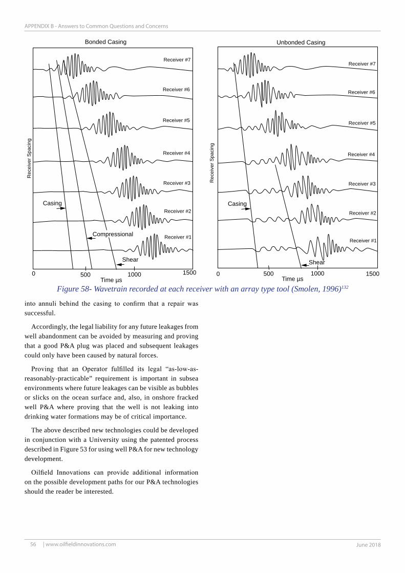
56 June 2018 | www.oilfieldinnovations.com
APPENDIX B - Answers to Common Questions and Concerns
Casing
Compressional
Shear
Casing
Shear
0 15001000500 0 15001000500Time µs Time µs
Bonded Casing Unbonded Casing
Receiver #7
Receiver #6
Receiver #5
Receiver #4
Receiver #3
Receiver #2
Receiver #1
Receiver #7
Receiver #6
Receiver #5
Receiver #4
Receiver #3
Receiver #2
Receiver #1
Rec
eive
r Spa
cing
Rec
eive
r Spa
cing
Figure 58- Wavetrain recorded at each receiver with an array type tool (Smolen, 1996)132
into annuli behind the casing to confirm that a repair was successful.
Accordingly, the legal liability for any future leakages from well abandonment can be avoided by measuring and proving that a good P&A plug was placed and subsequent leakages could only have been caused by natural forces.
Proving that an Operator fulfilled its legal “as-low-as-reasonably-practicable” requirement is important in subsea environments where future leakages can be visible as bubbles or slicks on the ocean surface and, also, in onshore fracked well P&A where proving that the well is not leaking into drinking water formations may be of critical importance.
The above described new technologies could be developed in conjunction with a University using the patented process described in Figure 53 for using well P&A for new technology development.
Oilfield Innovations can provide additional information on the possible development paths for our P&A technologies should the reader be interested.

57June 2017 |
APPENDIX B- Answers to Common Questions and Concerns
www.oilfieldinnovations.com
Figure 59 - Thermite Tear-drop Effect Figure 60 - Thermite Plugs in Oil and Gas Wells
Charge Emplacement
Charge
Ignition Cooling
Igniter
Lowry, et. al, Ceramic Plugging in purposely designed well
MechanicalPlug
Charge Emplacement
Charge
Ignition
GranularMaterial
SedimentaryRock
Fluid Expansion
UnbridgedAnnulus
Graniteor Basalt
Cooling
Igniter
Ceramic Plug Process in an Oil and Gas Well
MechanicalPlug
Path of LeastResistance
Annulus Fluid By-Pass Flow
Micro-Annuli Thermal Creation and/or By-Pass Flow
ThermalFluid
Fracking
ThermalFluidFracking
Thermite Ignition2500 deg. C4532 deg. F
Flow ofMolten
Material
CEM
ENT
CEMEN
TCASI
NG
CASIN
GTUBI
NG
TUBIN
G
Compare your method with Thermite P&A
The two methods are not mutually exclusive as they can be combined to provide a cost effective solution.
Within social media, where scientific evidence is not necessarily pertinent, thermite may be an appealing solution that removes the thought process by annihilating the well bore but, unfortunately, the uncontrollable nature of thermite can make it a problem and not a solution for thru-tubing thermite burning temperatures of 2,500 deg. C, as shown in Figure 59.
Lowry31 , et al., teach a controlled self-sintering ceramic plugs, which are placed in an open granite or basalt bore on top of a granular material filled borehole. Unfortunately, oil and gas wells are predominately in porous sedimentary rock with potentially high fluid content, wherein economic use of such a plug requires thru-tubing placement.
A shown in the lower part of Figure 60, oil and gas through-production-tubing “thermite only plugging” may require larger quantities of thermite to bridge large annuli gaps to melt a large volume of surrounding rock.
Rapid and extreme expansion of superheated trapped annuli and rock fluids could burst casing and fracture rock before being displaced upward or outward as molten material
travels downward to create additional annuli and leak paths around the perimeter of the well bore.
Provided fluids are allowed to spew from the top of the well, aging and decrepit wellhead equipment may, for the most part, avoid being burst or blown from the well when igniting large quantities of thermite.
Oilfield Innovations applauds Lowry’s and his co-contributors’ work and believe that it may be a valuable contribution, wherein the combination of a self-sintering ceramic plug process with our compaction method may mitigate the risks and provide a viable solution.
Our method of tubing compaction could remove the tubing and associated annuli gaps through which thermite might fall. It also allows logging the condition and fluid content of the surrounding geology to measure whether a ceramic plug can be welded to the cap rock without fracking. Finally, our piston supported by compacted tubing could be composed of a Kevlar bag of granular sealing material that provides a fireproof base for backfilled granular materials needed to hold and weld a self-sintering mix of thermite and inert materials to the rock of the well bore.
Accordingly, Oilfield Innovations method could be used to enable use of thermite ceramic plugs within oil and gas wells.