united states patent us 7,315,678 b2 a - nasa · (12) united siegel et a states patent (54) method...
TRANSCRIPT

(12) United Siegel et a
States Patent
(54) METHOD AND APPARATUS FOR LOW-LOSS SIGNAL TRANSMISSION
(75) Inventors: Peter Siegel, La Canada, CA (US); Cavour Yeh, Los Angeles, CA (US); Fred Shimabukuro, Rancho Palos Verde, CA (US); Scott Fraser, La Canada-Flintridge, CA (US)
(73) Assignee: California Institute Of Technology, Pasadena, CA (US)
Subject to any disclaimer, the term of this patent is extended or adjusted under 35 U.S.C. 154(b) by 0 days.
( * ) Notice:
(21) Appl. No.: 11/300,639
(22) Filed: Dec. 13, 2005
(65) Prior Publication Data
US 200610165360 A1 Jul. 27, 2006
Related U.S. Application Data
(60) Provisional application No. 601635,846, filed on Dec. 13, 2004.
(51) Int. C1.
(52) U.S. C1. ....................... 385/125; 3851117; 3851123 (58) Field of Classification Search ................ 3851117,
3851123, 125; 3331239, 242, 248
G02B 6/02 (2006.01)
See application file for complete search history.
(56) References Cited
U.S. PATENT DOCUMENTS
4,458,229 A * 7/1984 Landry et al. .............. 333/248 5,638,478 A * 6/1997 Iwakura et al. ............. 385/111
(io) Patent No.: (45) Date of Patent:
US 7,315,678 B2 Jan. 1,2008
6,975,898 B2 * 12/2005 Seibel ........................ 600/473 2004/0175082 A1 * 9/2004 Birks et al. ................. 385/123
FOREIGN PATENT DOCUMENTS
EP 1541090 A1 * 6/2005 WO WO 2002/101430 A1 * 12/2002 WO WO 2002101430 A1 * 12/2002
OTHER PUBLICATIONS
B.J. Mangan, L. Farr, A. Langford, P.J. Roberts, D.P. Williams, F. Couny, M. Lawman, M. Mason, S. Coupland, R. Flea, H. Sabert, T.A. Birks, J.C. Knight and P. J. Russell, “Low loss (1.7dB/km) hollow core photonic bandgap fiber,” Optical and Fiber C o r n . Conf (OFC-2004) post deadline paper PDP24, Los Angeles, CA, Feb. 22-27, 2004.
(Continued)
Primary Examiner-Frank G. Font Assistant Examiner-Hung Lam (74) Attorney, Agent, or Firm-Tope-McKay & Associates
(57) ABSTRACT
The present invention relates to the field of radio-frequency (RF) waveguides. More specifically, the present invention pertains to a method and apparatus that provides ultra-low- loss RF waveguide structures targeted between approxi- mately 300 GHz and approximately 30 THz. The RF waveguide includes a hollow core and a flexible honey- comb, periodic-bandgap structure surrounding the hollow core. The flexible honeycomb, periodic-bandgap structure is formed of a plurality of tubes formed of a dielectric material such as of low-loss quartz, polyethylene, or high-resistivity silicon. Using the RF waveguide, a user may attach a terahertz signal source to the waveguide and pass signals through the waveguide, while a terahertz signal receiver receives the signals.
21 Claims, 6 Drawing Sheets
200
J
02
https://ntrs.nasa.gov/search.jsp?R=20080018812 2018-06-02T10:54:43+00:00Z
US 7,315,678 B2 Page 2
OTHER PUBLICATIONS
T.A. Birks, D. Mogilevtsev, J.C. Knight and P.J. Russell, “Disper- sion compensation using single-material fibers,” IEEE Photonics Technology Letters, vol. 11, No. 6, pp. 674-676, Jun. 1999. Philip Russell, “Photonic Crystal Fibers,” Science, v.299, pp. 358- 362, Jan. 17, 2003. G. Humbert, J.C. Knight, G. Bouwmans, P. J. Russell, D.P. Will- isms, p, J, Roberts and B, J, Mangan, “Hollow core photonic crystal fibers for beam delivery,” optics E ~ ~ ~ ~ ~ ~ , vel, 12, N ~ , 8, pp,
J.C. Knight, T.A. Birks, P.J. Russell and D.M. Atkin, “All-silica single-mode optical fiber with photonic crystal cladding,” Optics Letters, vol. 21, No. 19, pp. 1547-1549, Oct. 1, 1996. G. Humbert, J.C. Knight, G. Bouwmans, P. J. Russell, D.P. Will- iams, P.J. Roberts and B.J. Mangan, “Hollow core photonic crystal fibers for beam delivery,” Optics Express, ~ 0 1 . 12, No. 8, pp. 1477-1484, A9 Apr. 2004. H. Han, H. park, M. Cho, J. Kim, I. Park and H. Lim, “Terahertz pulse propagation in plastic photonic crysta1 fibers,” 2o02 IEEE MTT-S Int. Mic. SYm. Digest, vel. 2, PP. 1075-1078, Juri. 7, 2002.
1477-1484, Apr. 19, 2004. * cited by examiner

U.S. Patent Jan. 1,2008 Sheet 1 of 6 US 7,315,678 B2
0 0

U.S. Patent Jan. 1,2008 Sheet 2 of 6 US 7,315,678 B2
cv 0

U.S. Patent Jan. 1,2008 Sheet 3 of 6
0 / 0 c')
co 0 c') /
US 7,315,678 B2
U.S. Patent Jan. 1,2008 Sheet 4 of 6 US 7,315,678 B2

U.S. Patent Jan. 1,2008 Sheet 5 of 6 US 7,315,678 B2
a c5 co
LL
I\
\l
@ /
\
2, 0 Lo

U.S. Patent Jan. 1,2008 Sheet 6 of 6 US 7,315,678 B2
cv - 0 b
LL
‘ 0 0 l-

US 7,315,678 B2 1
METHOD AND APPARATUS FOR LOW-L,OSS SIGNAL TRANSMISSION
PRIORITY CLAIM
The present application claims the benefit of priority of U.S. Provisional Patent Application No. 601635,846, filed Dec. 13, 2004, and entitled “Hollow-core periodic bandgap flexible dielectric waveguide for low-loss THz signal trans- mission.”
STATEMENT OF GOVERNMENT INTEREST
The invention described herein was made in the perfor- mance of work under a NASA contract, and is subject to the provisions of Public Law 96-517 (35 USC 202) in which the Contractor has elected to retain title.
BACKGROUND OF THE INVENTION
(1) Technical Field The present invention relates to the field of radio-fre-
quency (RF) waveguides. More specifically, the present invention pertains to a method and apparatus that provides ultra-low-loss (less than 1 dB per meter) RF waveguide structures targeted between 300 GHz and 30 THz.
(2) Background RF waveguides are based on the theory of wave propa-
gation. The theory of wave propagation in periodic struc- tures was developed several years ago. That theory provided fundamental understanding in solid-state physics and x-ray diffraction. Since then, the theory has been expanded for many other applications, such as traveling wave tubes, bandpass filters, distributed feedback lasers, integrated optics structures, dichroic plates, artificial dielectrics, etc. Most recently, photonic periodic structures (or photonic crystals) using the same basic theory have been developed for a wide range of traveling wave applications in both the microwave and optical regions of the electromagnetic spec- trum. The periodic nature of the photonic crystal elements allows propagation over a restricted band of wavelengths, thus allowing filters, couplers, power splitters, waveguides and many other components, to be realized. The construc- tions that give rise to this frequency-dependent behavior are commonly termed “photonic bandgap structures” (PBG structures).
Hollow core photonic bandgap fiber has been developed in large part by P. J. Russell, J. C. Knight and colleagues at the University of Bath (located at BA2 7AY, United King- dom) over the past 10 years, as disclosed in the following papers:
(1) Philip Russell, “Photonic Crystal Fibers,” Science, v.299, pp. 358-362, Jan. 17, 2003.
(2) G. Humbert, J. C. Knight, G. Bouwmans, P. J. Russell, D. P. Williams, P. J. Roberts and B. J. Mangan, “Hollow core photonic crystal fibers for beam delivery,” Optics Express, Vol. 12, no. 8, pp. 1477-1484, 19Apr., 2004.
(3) B. J. Mangan, L. Farr, A. Langford, P. J. Roberts, D. P. Williams, F. Couny, M. Lawman, M. Mason, S. Coupland, R. Flea, H. Sabert, T. A. Birks, J. C. Knight and P. J. Russell, “Low loss (1.7 d B h ) hollow core photonic bandgap fiber,” Optical and Fiber Comm. Conf (OFC-2004) post deadline paper PDP24, Los Angeles, Calif., Feb. 22-27, 2004.
(4) T. A. Birks, D. Mogilevtsev, J. C. Knight and P. J. Russell, “Dispersion compensation using single-material fibers,” IEEE Photonics Technology Letters, vol. 11, no. 6, pp. 674-676, June 1999.
2 (5) J. C. Knight, T. A. Birks, P. J. Russell and D. M. Atkin,
“All-silica single-mode optical fiber with photonic crystal cladding,” Optics Letters, vol. 21, no. 19, pp. 1547-1549, Oct. 1, 1996.
These investigators have targeted the optical fiber com- munity, especially the near infrared, and optimized hollow core (HC)-PBG structures for both low-loss and high power continuous wave (CW) and pulsed propagation between 1 and 2 microns, with potential extension to 10 microns
The article by Knight and Russell et al. discloses a hollow core photonic bandgap fiber developed for 1.5 micron propagation. The core is 20 microns in diameter and the honeycomb is approximately 4 microns. The material
15 employed is silica and the structures are extruded through a mandrel in a hot-melt process, allowing for the fabrication of many geometries.
Knight and Russell et al. developed another optical HC- PBG design, which is disclosed in G. Humbert, J. C. Knight,
20 G. Bouwmans, P. J. Russell, D. P. Williams, P. J. Roberts and B. J. Mangan, “Hollow core photonic crystal fibers for beam delivery,” Optics Express, Vol. 12, no. 8, pp. 1477-1484, A9 April, 2004. This second design disclosed a reduced diam- eter core and substantially higher propagation loss. Knight
25 and Russell et al. focused on 7-cell and 19-cell core designs. The idea of using photonic bandgap structures for tera-
hertz waveguide propagation was published by H. Han, H. Park, M. Cho and J. Kim, in “Terahertz pulse propagation in plastic photonic crystal fibers,” Lasers and Electro-optics,
30 2001 and CLEOiPacific Rim 2001, Volume: Supplement, paper WIPD1-10, pp. 22-23, 19 Jul. 2001, and later embel- lished in H. Han, H. Park, M. Cho, J. Kim, I. Park and H. Lim, “Terahertz pulse propagation in plastic photonic crystal fibers,” 2002 IEEE MTT-S Int. Mic. Sym. Digest, vol. 2, pp.
Hans et al. disclosed a plastic PBG guide with a solid polyethylene core and surrounding an equal-sized honey- comb sheath for terahertz pulse propagation. However, the measured loss is high, greater than 5 decibels per centimeter
The above-mentioned PBG guides are typically used for fiber optic communications. However, such PBG guides are not suitable for use in terahertz endoscopes and fiberscopes. Accordingly, a need exists for an apparatus and method that
45 provides a low-loss radio-frequency (RF) waveguide struc- tures between sub-millimeter (300 GHz) and far-infrared (30 THz).
5
i o wavelength.
35 1075-1078, Jun. 7, 2002.
40 (dB1cm) at 400 gigahertz (GHz).
SUMMARY OF THE INVENTION 50
The present invention provides a system and a method that overcomes the aforementioned limitations and fills the aforementioned needs by providing a method and apparatus for ultra-low loss RF waveguide structures targeted between
55 300 GHz and 30 THz. This new structure uses a hollow core rather than the solid
core of Han et al., thereby reducing losses and making long path length propagation possible for both endoscope or fiberscope operation. It also allows low-loss single mode
60 propagation of energy in the frequency range from 300 GHz to 30 THz, as well as simple coupling into and out of fundamental mode waveguide horns that are inserted in the core of the guide in order to launch into the fiber.
The low-loss RF waveguide comprises a hollow core and 65 a flexible honeycomb, periodic-bandgap structure surround-
ing the hollow core. The low-loss RF waveguide is formed to operate between 300 GHz and 30 THz.

US 7,315,678 B2 3 4
Additionally, the flexible honeycomb, periodic-bandgap structure comprises a plurality of tubes having approxi- mately equal size. The tubes are composed of a material selected from a group consisting of low-loss quartz, poly- ethylene, and high-resistivity silicon. In another aspect, the 5 hollow core is over-moded and has a circular cross-section.
In another aspect, a ribbon-guide is positioned within the The objects, features and advantages of the present inven- hollow core such that the hollow core has a first cross- tion will be apparent from the following detailed descrip- sectional dimension and a second cross-sectional dimension, tions of the various aspects of the invention in conjunction wherein the first cross-sectional dimension is not equal to i o with reference to the following drawings, where: the second cross-sectional dimension. FIG. 1 is a cross-sectional illustration a low-loss RF
In yet another aspect, the present invention further com- prises a conical feedhorn attached with the hollow core. FIG. 2 is a cross-sectional illustration of a hybrid structure
The present invention also relates to a fiberscope. The fiberscope comprises a low-loss RF waveguide and a tera- 15 FIG. 3 is an illustration of an exemplary application ofthe hertz signal source coupled with the low-loss RF waveguide. The low-loss RF waveguide includes a hollow core and a FIG. 4 is an illustration of an exemplary application of the flexible honeycomb, periodic-bandgap structure surround- ing the hollow core. Additionally, the low-loss RF FIG. 5 is an illustration of a hollow-core, periodic- waveguide is configured to operate between 300 GHz and 30 20 bandgap (HC-PBG) structure according to the present inven- THz. A beam splitter is located within the low-loss RF tion, with input and output homs to launch a desired mode; waveguide for polarizing a signal passed through the FIG. 6A is an illustration of an exemplary analysis indi- waveguide. A terahertz signal receiver is coupled with the cating a low dispersion propagating mode with a confined beam splitter to receive a reflected signal. electrostatic field (E plane field);
FIG. 6B is an illustration of an exemplary analysis indi- hollow core and positioned between the low loss-RF cating a low dispersion propagating mode with a confined waveguide and the terahertz signal source. magnetic field (H plane field);
In another aspect, the present invention includes a method FIG. 7A is an illustration of an exemplary HC-PBG for guiding RF signals. The method comprises acts of structure for operation at 350 GHz; and forming a flexible honeycomb, periodic-bandgap structure 30 FIG. 7B is an illustration of an exemplary HC-PBG around a hollow core, resulting in a low-loss RF waveguide, structure for operation at 1200 GHz. such that the RF waveguide is operable for receiving RF signals in the range of approximately 300 GHz to approxi- mately 30 THz.
The present invention relates to the field of radio-fre- approximately equal size to form the flexible honeycomb, quency (RF) waveguides. More specifically, the present periodic-bandgap structure. Additionally, the act of arrang- invention pertains to a method and apparatus that provides ing includes an act of selecting and forming the tubes of a ultra-low-loss RF waveguide structures targeted between material selected from a group consisting of low-loss quartz, 300 GHz and 30 THz. The following description, taken in polyethylene, and high-resistivity silicon. The act of forming 40 conjunction with the referenced drawings, is presented to further includes an act of arranging the flexible honeycomb, enable one of ordinary skill in the art to make and use the periodicic-bandgap structure such that the hollow core has a invention and to incorporate it in the context of particular circular cross-section. applications. Various modifications, as well as a variety of
In another aspect, the act of forming further includes an uses in different applications will be readily apparent to act positioning a ribbon-guide within the hollow core such 45 those skilled in the art, and the general principles defined that the hollow core has a first cross-sectional dimension and herein may be applied to a wide range of embodiments. a second cross-sectional dimension, whereby the first cross- Thus, the present invention is not intended to be limited to sectional dimension does not equal the second cross-sec- the embodiments presented, but is to be accorded the widest tional dimension. scope consistent with the principles and novel features
In another aspect, the method further comprises acts act of 50 disclosed herein. Furthermore, it should be noted that, unless coupling a terahertz signal source to the low-loss RF explicitly stated otherwise, the figures included herein are waveguide; and coupling a conical feedhorn between the illustrated diagrammatically and without any specific scale, terahertz signal source and the low-loss RF waveguide such as they are provided as qualitative illustrations of the con- that the conical feedhorn fits into the hollow core. cept of the present invention.
In the following detailed description, numerous specific of inserting a beam splitter into the low-loss RF waveguide; details are set forth in order to provide a more thorough and coupling a terahertz signal receiver to the beam splitter. understanding of the present invention. However, it will be
The present invention also relates to a method of imaging, apparent to one skilled in the art that the present invention comprising acts of utilizing the low-loss RF waveguide; may be practiced without necessarily being limited to these passing a signal having a frequency in the range of 300 GHz 60 specific details. In other instances, well-known structures to 30 THz into the low-loss RF waveguide; reflecting the and devices are shown in block diagram form, rather than in signal off of an object, resulting in a reflected signal; and detail, in order to avoid obscuring the present invention. receiving the reflected signal. The act of receiving the The reader’s attention is directed to all papers and docu- reflected signal further comprises acts of utilizing a beam ments which are filed concurrently with this specification splitter inserted into the low-loss RF waveguide; and receiv- 65 and which are open to public inspection with this specifi- ing the reflected signal with a receiver coupled with the cation, and the contents of all such papers and documents are beam splitter. incorporated herein by reference. All the features disclosed
Finally, in the act of utilizing a low-loss RF waveguide, the RF waveguide includes a ribbon-guide positioned within the hollow core.
BRIEF DESCRIPTION OF THE DRAWNGS
waveguide according to the present invention;
according to the present invention;
present invention;
Present invention;
In another aspect, a conical feedhorn is attached with the 25
DETAILED DESCRIPTION
The act of forming includes an act of arranging tubes of 35
In yet another aspect, the method further comprises acts 55

US 7,315,678 B2 5 6
in this specification (including any accompanying claims, odic-bandgap structure 104. In this aspect, as a non-limiting abstract, and drawings) may be replaced by alternative example, the diameter of the hollow core 102 is approxi- features serving the same, equivalent or similar purpose, mately 720 micrometers. As can be appreciated by one unless expressly stated otherwise. Thus, unless expressly skilled in the art, the dimensions described herein are for stated otherwise, each feature disclosed is one example only 5 illustrative purposes only and are not intended to be limiting of a generic series of equivalent or similar features.
Furthermore, any element in a claim that does not explic- itly state “means for” performing a specified function, or “step for” performing a specific function, is not to be interpreted as a “means” or “step” clause as specified in 35 i o U.S.C. Section 112, Paragraph 6. In particular, the use of “step of’ in the claims herein is not intended to invoke the provisions of 35 U.S.C. Section 112, Paragraph 6.
Below, a brief introduction is provided in the form of a narrative description of the present invention to give a 15
thereto. The diameter of each of the tubes 106 making up the honeycomb periodic bandgap structure 104 is approximately 180 micrometers (p). Although individual tubes 106 can differ in size, it is desirable that the tubes 106 be equally- sized. In the above dimensions, the overall diameter of the low-loss, flexible waveguide 100 is approximately 2 milli- meters. A small overall diameter allows for flexible move- ment when the honeycomb, periodic-bandgap structure 104 is made of a plastic. Alternatively, the small overall diameter provides a slightly more restrictive movement when the
conceptual understanding prior to developing the specific details. Next, a detailed explanation of various aspects is provided in order to enable the reader to make and use the various embodiments of the invention without involving undue experimentation.
(1) Introduction Disclosed herein is a new class of ultra-low-loss radio
frequency (RF) waveguide structures targeted at frequencies between approximately 300 gigahertz (GHz) and 30 tera- hertz (THz). also referred to as the “Terahertz Gan.” The
honeycomb, periodic-bandgap structure 104 is made from silicon or quartz.
The dimensions provided in FIG. 1 have been optimized for 2.5 THz operation. Optimization for other frequency
20 ranges can be obtained by direct scaling or using a finite- difference time-domain (FDTD) code. Geometric shape, configuration, and aperture dimensions may be adjusted to optimize propagation and stop bands as well as matching into and out of feedhorns. Further, materials selected may be
25 altered in order to ontimize the low-loss RF waveguide for , ,l u
guide medium takes the form of a hollow-core, periodic- other frequency ranges. For example, non-uniform PBG bandgap (HC-PBG) structure. The HC-PBG structure sheath characteristics (such as size and index variations) includes a honeycomb array of tubes around an oversized may be used to optimize mode confinement and purity. (multi-mode) hollow core. The hollow core 102 is over-moded and has a circular
The geometric arrangement of the HC-PBG structure and 30 cross-section. The tubes 106 comprising the honeycomb, the selected materials provide for a HC-PBG structure being periodic-bandgap structure 104 may be manufactured from operable over a much wider wavelength range than other a variety of materials, non-limiting examples of which HC-PBG structures. The surrounding honeycomb periodic- include low-loss quartz tubing, polyethylene or high-resis- bandgap structure possesses band-gapistop behavior for tivity silicon. The geometry, size, and spacing of the tubes fields of the guided wave penetrating into that structure, 35 106 may be varied in order to optimize the low-loss RF resulting in the confinement of the wave within the central waveguide 100 for any of a variety of frequencies from core or hole over a desired propagation band. The hollow approximately 300 GHz to 30 THz. In one aspect, it is core and the honeycomb periodic structure results in the desirable for the tubes 106 to have approximately equal propagating fields lying almost entirely in air, thereby pro- cross-sectional geometry. viding propagating fields that have minimal absorptive loss. 40 In order to launch a single confined mode into the PBG Compared to existing guide media, the HC-PBG structure core, a conical feedhom is inserted fully into the central hole has lower propagation loss in the terahertz region by several of the PBG structure. Coupling out of the PBG guide is orders of magnitude. Existing guide media are typically accomplished in the same manner. The feedhom taper and formed from metallic or dielectric waveguide. For such aperture diameter are designed to match the PBG core 102 existing waveguides, resistive skin effect loss in non-perfect 45 diameter. Simulations using FDTD analysis show good conductors and vibrational phonon absorptive loss in dielec- matching into the waveguide with this arrangement. A trics combine to make low-loss RF propagation impossible. non-limiting example of such a feedhom includes a simple,
Further, the disclosed HC-PBG structure provides a flex- dual-mode Pickett-Potter horn. The Picket-Potter horn was ible, low-loss guide medium for terahertz frequencies (i.e., described in the following publication: “Characterization of wavelengths from roughly 1 mm to 10 microns). As a 50 a Dual Mode Horn for Sub-millimeter Wavelengths,” IEEE non-limiting example, the disclosed HC-PBG structure can Trans. Microwave Theory and Techniques, vol. MTT-32, no. be utilized in the development of THz endoscopes and 8, Aug. 1984, pp. 936-8. fiberscopes, opening up the first in-vivo use of terahertz FIG. 2 depicts a cross-sectional view of another aspect of signals. Other exemplary uses for the guide medium include the present invention. FIG. 2 illustrates a hybrid structure low-loss, flexible THz waveguides for efficient sensor and 55 200 comprising a dielectric ribbon-guide 202 supported by source coupling; chip-to-chip RF interconnects; reconfig- a honeycomb, periodic-bandgap structure 204 (formed of a urable beam waveguides; and any application where guided plurality of tubes 206). Variations to the core structure result RF power distribution is desired. Additionally, the present in a hybrid structure 200 which combines the properties of invention includes a system and method for efficient input/ a THz ribbon-guide and a hollow-core, periodic-bandgap output coupling for RF excitation and detection as well as a 60 guide. This ribbon-guide 202 can be composed of any mechanism of combining the HC-PBG with an alternate suitable dielectric material, non-limiting examples of which low-loss RF guide concept (Le., inclusion of a terahertz include high resistivity silicon, quartz, low-loss plastic such ribbon). as polyethylene or polypropylene, kapton, polyethylene and
(2) Detailed Explanation polypropylene. For example, a quartz ribbon can be utilized FIG. 1 depicts a cross-sectional view of one aspect of a 65 that is formed gluing together 10 circular fibers of 100
micron diameter to form a 1000x100 micron cross section ribbon.
low-loss RF waveguide 100. The low-loss RF waveguide 100 comprises a hollow core 102 and a honeycomb, peri-
US 7,315,678 B2 7
The ribbon-guide 202 is positioned within the hollow core 203 such that the hollow core has a first cross-sectional dimension 212 that is not equal to a second cross-sectional dimension 214. The ribbon-guide 202 has a dimension in a first direction 208 (width) of approximately one-half wave- length, and a dimension in a second direction 210 (thick- ness) of approximately a tenth of a wavelength. In this aspect, the propagating mode is pinned to the ribbon-guide 202, reducing the hollow core 203 diameter 212 to 2-5 wavelengths. The honeycomb, periodic-bandgap structure
8 low-loss RF waveguide 402 comprises a beam splitter 412, such as a polarizing beam splitter. As a non-limiting example, the beam splitter 412 is a 45 degree wire-grid beam splitter. Using the beam splitter 412, the THz signal source
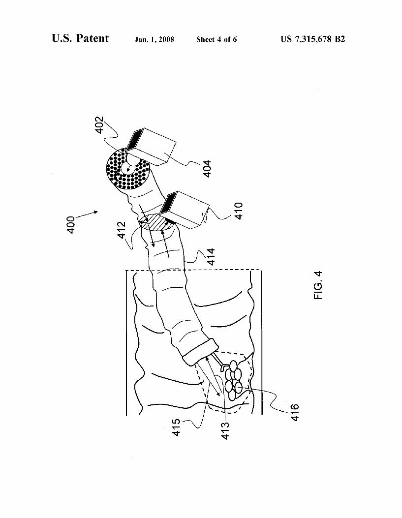
5 404 may transmit one polarization signal (having a fre- quency) 415 to be reflected by an object 416, while the reflection of the THz signal 413 will be in another polar- ization signal. In this aspect, the beam splitter 412 can separate the polarization and ensure that the reflected signal
i o 413 is passed to the THz signal receiver 410. 204 provides the isolation required to handle the waveguide For applications in in-vivo imaging via a fiberscope or an while retaining the flexibility and low-loss guiding proper- endoscope, the low-loss RF waveguide 302 may be sealed in ties. Some advantages of this embodiment are greater design a commercially or specially fabricated insertion tube 310 freedom and a smaller cross-sectional area. (FIG. 3) or 414 (FIG. 4), with a thin resonant window (not
The low-loss RF waveguide of the present invention can 15 shown). The resonant window is located at the end where the be used in a variety of applications, such as in-vivo imaging THz source 304 and 404 connects with the low-loss RF with endoscope and fiberscope tools, long length terahertz waveguide 302 or 402. Using the fiberscope or endoscope, propagation in an undisturbed environment, and vacuum imaging can be performed with fixed frequencies or with propagation (by sealing off and pumping out the core). The chirped or scanned frequencies providing depth andor spec- geometry, size, and spacing of the tubes 106 (as shown FIG. 20 troscopic information. 1) and 206 (as shown in FIG. 2) may be optimized to provide FIG. 5 shows an exemplary arrangement of a PBG guide continuous wave propagation of narrow frequency bands. 500 with an input horn 502 and an output horn 504 to launch For example, the low-loss RF waveguides may be optimized the desired HEll mode. A mode is the particular geometric for use in narrow frequency bands centered around 2.5 THz field pattern that propagates the pattern through the device. and 650 GHz, two frequencies that are known to be useful 25 HEll is the electrostatic field (E-field) verticalimagnetic for imaging applications in the submillimeter area. An field (H-field) horizontal, Gaussian power distribution (cen- advantage of the low-loss RF waveguides is that they can ter-to-edge) that propagates from a typical conical or pyra- bend or twist without distorting internal fields, which is not midal quality feed horn. As shown in FIG. 5, the horns 502 possible with metallic waveguides or fixed optical beams. and 504 are conical in shape and cover the hollow core.
An example of one application is shown in FIG. 3, which 30 Although also conical, due to the orientation of the illustra- depicts a first THz fiberscope 300. The THz fiberscope tion in FIG. 5, the conical portion of the output horn 504 is comprises a low-loss RF waveguide 302 coupled with a THz not shown. signal source (multiplier) 304 that injects an RF signal FIGS. 6A and 6B depict an analysis of field confinement directly into the hollow core 308. In this aspect, the THz using waveguide horns to launch a desired mode. As shown signal source 304 has a waveguide horn 306 which fits inside 35 in FIG. 6A, the analysis indicates a low dispersion propa- the hollow core 308 of the low-loss RF waveguide 302. A gating mode with a confined electrostatic field (E plane return signal is picked up by a second THz fiberscope where field). Additionally, FIG. 6B depicts an analysis indicating a the THz signal source 304 is replaced with a THz signal low dispersion propagating mode with a confined magnetic receiver. In this aspect, a parallel HC-PBG waveguide field (H plane field). (second fiberscope) port is inserted into the fiberscope 300 40 FIGS. 7A and 7B depict exemplary HC-PBG guides 700 (or endoscope) with an external detector on the output side for operation at 350 GHz and 1200 GHz respectively. In (also coupled into the HC-PBG guide using an inserted feed these examples, the HC-PBG guide 700 was fabricated from horn). commercially available Teflon tubes 702 wrapped with thin
The feedhorn is a mode launching antenna. The feedhorn Teflon tape 704 around a hollow Teflon tube core 706. As takes input power from a source (which can be a waveguide, 45 shown in FIG. 7B, the smaller tubes 702 and smaller transmission line or active power generator) and gradually diameter of the tube core 706 provide for higher GHz converts the power into a propagating mode that matches to operation. a plane wave in free space. Typically, the designation “feed” What is claimed is: refers to the fact that the horn is matching or feeding the 1. A low-loss RF waveguide, comprising: power to some other beam forming network (like a parabolic 50 a hollow core; antenna in the case of a radio telescope), or to free space. a flexible honeycomb, periodic-bandgap fiber surround- The “horn” portion indicates that the geometric form is ing the hollow core, wherein the low-loss RF similar to that of a sound forming wind instrument. Essen- waveguide is formed to operate in a range of approxi- tially, it provides the same function, matching the sound mately 300 GHz to approximately 30 THz; and wave in the instrument to free space for maximum trans- 55 a dielectric ribbon-guide positioned within the hollow mitted power. Horns are typically either conical or pyrami- core such that the hollow core has a first cross-sectional dal, but they can take many other shapes as well, depending dimension and a second cross-sectional dimension, on the inputioutput fields being propagatedigenerated. wherein the first cross-sectional dimension is not equal Although other horn shapes can be used in the present to the second cross-sectional dimension. invention, a conical horn (the most common millimeter 60 2. A low-loss RF waveguide as set forth in claim 1, wave power launcher) is desirable because it matches the wherein the flexible honeycomb, periodic-bandgap fiber PBG guide core and launches a nice propagating Gaussian comprises a plurality of tubes having approximately equal mode in to the PBG guide itself. cross-sectional geometry.
FIG. 4 depicts another exemplary THz fiberscope 400. As 3. A low-loss RF waveguide as set forth in claim 2, shown in FIG. 4, the THz fiberscope 400 comprises a 65 wherein the tubes are formed of a material selected from a low-loss RF waveguide 402 coupled with a THz signal group consisting of low-loss quartz, polyethylene, and high- source 404 and a THz signal receiver 410. Additionally, the resistivity silicon.
US 7,315,678 B2 9 10
4. A low-loss RF waveguide as set forth in claim 1, wherein the hollow core is over-moded.
5. A low-loss RF waveguide as set forth in claim 1, wherein the flexible honeycomb, periodic-bandgap fiber is composed of material a selected from a group consisting of 5 low-loss quartz, polyethylene, and high-resistivity silicon.
6. A low-loss RF waveguide as set forth in claim 1,
dimension and a second cross-sectional dimension, wherein the first cross-sectional dimension is not equal to the second cross-sectional dimension; resulting in a low-loss RF waveguide such that the RF waveguide is operable for receiving RF signals in the range of approximately 300 GHz to approximately 30 THz.
13. A method as set forth in claim 12, wherein the act of
equal size to form the flexible honeycomb, periodic-bandgap
14. A method as set forth in claim 13, wherein the act of arranging includes an act of selecting the tubes formed of a material selected from a group consisting of low-loss quartz, polyethylene, and high-resistivity silicon.
forming includes an act of manufacturing the flexible hon- eycomb, periodic.bandgap fiber from a material selected from a group consisting of low-loss quartz, polyethylene, and high-resistivity silicon.
16. A method as set forth in claim 12, wherein the act of
honeycomb, periodic-bandgap fiber such that the hollow core has a circular cross-section.
17. A method as Set forth in claim 12, further comprising an act of coupling a terahertz signal source to the low-loss
18. A method as set forth in claim 17, further comprising an act of coupling a conical feedhorn between the terahertz
30 signal source and the low-loss RF waveguide such that the conical feedhorn fits into the hollow core.
19. A method as set forth in claim 12, further comprising
inserting a beam splitter into the low-loss RF waveguide;
coupling a terahertz signal receiver to the beam splitter. 20. A method of imaging, the method comprising acts of: utilizing a low-loss RF waveguide, where the low-loss RF
a hollow core; a flexible honeycomb, periodic-bandgap fiber surround-
ing the hollow core; and a dielectric ribbon-guide positioned within the hollow
core such that the hollow core has a first cross-sectional dimension and a second cross-sectional dimension, wherein the first cross-sectional dimension is not equal to the second cross-sectional dimension;
passing a signal having a frequency in the range of approximate~y 300 G H ~ to approximate~y 30 T H ~ into the low-loss RF waveguide;
reflecting the of an object, resulting in a reflected signal; and receiving the reflected signal.
21. A method as set forth in claim 20, wherein the act of
utilizing a beam splitter inserted into the low-loss RF
receiving the reflected signal with a receiver coupled with
wherein the hollow core has a substantially circular cross- forming includes an act of arranging tubes of approximately section.
comprising a conical feedhorn attached with the hollow core.
7. A low-loss RF waveguide as set forth in claim 1, further i o fiber.
8. A low-loss RF waveguide, comprising: a hollow core; a honeycomb, periodic-bandgap fiber surround- l5 15, A method as set forth in claim 12, wherein the act of ing the hollow core; a dielectric ribbon-guide positioned within the hollow
core such that the hollow core has a first cross-sectional dimension and a second cross-sectional dimension, wherein the first cross-sectional dimension is not equal 20 to the second cross-sectional dimension; and
in a range o~approximate~y 300 G H ~ to approximate~y 30 THz;
wherein the flexible honeycomb, periodic-bandgap fiber 25 comprises a plurality of tubes having approximate~y equal cross-sectional geometry; RF waveguide.
wherein the tubes are formed of a material selected from a group consisting of low-loss quartz, polyethylene, and high-resistivity silicon;
wherein the low-10~~ RF waveguide is formed to operate forming further an act Of arranging the
wherein the hollow core is over-moded; and wherein the hollow core has a substantially circular
cross-section. acts of: 9. A fiberscope comprising: a low-loss RF waveguide, comprising: 35 and a hollow core; a flexible honeycomb, periodic-bandgap fiber surround-
ing the hollow core, wherein the low-loss RF waveguide operates in a range of approximately 300 GHz to approximately 30 THz; 4o waveguide comprises:
a dielectric ribbon-guide positioned within the hollow core such that the hollow core has a first cross-sectional dimension and a second cross-sectional dimension, wherein the first cross-sectional dimension is not equal to the second cross-sectional dimension; and
a terahertz signal source coupled with the low-loss RF waveguide.
10. A fiberscope as set forth in claim 9, further comprising a conical feedhorn attached with the hollow core and posi- tioned between the low loss-RF waveguide and the terahertz 50 signal source.
11. A fiberscope as set forth in claim 10, further compris- ing:
a beam splitter located within the low-loss RF waveguide;
45
and 55 a terahertz signal receiver coupled with the beam splitter, receiving the reflected further comprises acts Of:
12, A method for guiding RF signals, the method
forming a flexible honeycomb, periodic-bandgap fiber around a hollow core; and 60 the beam-splitter.
positioning a dielectric ribbon-guide within the hollow core such that the hollow core has a first cross-sectional
prising acts of: waveguide; and
* * * * *