united states patent patent number: ,o - ntrs.nasa.gov · united states patent [191 [ill patent...
TRANSCRIPT

United States Patent [191 [ill Patent Number: 5,705 ,O 18 Hartley [451 Date of Patent: Jan. 6,1998
MICROMACHINED PERISTALTIC PUMP
Inventor: Frank T. Hartley. 529 E. Las Flores Ave.. Arcadia, Calif. 91006
Appl. No.: 572,186
Filed Dec 13,1995
ht. CL6 ........................................................ B44c 1/22 U.S. C1. ................... 1 5 6 M ; 156/630.1; 15W657.1;
216/2; 216/33 Field of Search ................................. 156B45, 630.1,
156f657.1, 662.1; 21W2, 33.41; 417f474, 477,480
References Cited
U.S. PATENT DOCUMENTS
4,794,370 1211988 Simpson et al. . 5,380,3% 1/1995 Shikida et al. ....................... 15W630.1 5,585,011 12/1996 S& et al. ............................... 216/33
OTHER PUBLICXITONS
Preprint of “Design. Fabrication & Testing of a Miniature Peristaltic Membrane Pump,” by James A. Folta et al., Apr. 1992. prepared for Proceedings of the IEEE Solid State Sensor and Actuator Workshop, Hilton Head Island, South Carolina, held Jun. 21-25, 1992. “Design. Fabrication & Testing of a Miniature Peristaltic Membrane Pump,” by James A. Folta et al.. pp. 186189. Apr. 1992, Lawrence Livermore National Laboratory, Cali- fornia. “A Piezo-Electric Pump Driven by a Flexural Progressive Wave,” pp. 11&113, by Shun-ichi Miyazaki et al.. Seventh International Conference on Solid State Sensors and Actua- tors, held at Yokohama, Japan, on Juri. 7-10. 1993. “A Novel Piezoelectric Valve-Less Fluid Pump,” by Erik Stemme et al., 7th International Conference on Solid State Sensors & Actuators. pp. 110-113. Yokohama, Japan, Jun. 7-10. 1993.
“Pexformance Simulation of Microminiaturized Membrane Pumps,” by R. Zengerle. et al.. Fraunhofer Institute for Solid State Technology. Munich, Germany. “Peristaltic Pumpting,” by M.Y. JafFrin et al., 197 1, Depart- ment of Mechanical Engineering, Institute of Technology, Cambridge, Massachusetts. “F’iezoelectric Micropump with Three Valves Working Peri- staltically.” by Jan G. Smist, Sensors and Actuators (1990).
“A Micro Membrane Pump with Electrostatic Actuation.” by R. Zengerle et al., Micro Electro Mechanical Systems ’92, Travemunde, Germany, Feb. 4-7, 1992. “Electrohydrodynamic Pumping and Flow Measurement,” by A. Richter et al., pp. 271-276, Proceedings of the IFEE Micro Elwtro Mechanical Systems, Application of Micro Structure, Sensors. Actuators, Machines and Robots, Nara, Japan, Jan. 30-Feb. 2. 1992, New Yak, New York. U.S.A., IEEE 1991. “Dialog Search Abstract,” date Oct. 12. 1995, pp. 1-8. “Dialog Search Abstract,” date Ob., 1995. Primary Examiner-William Powell Attorney, Agent, or Firn+F’rice, Gess & Ubell
P71 ABSTRACT
A micromachined pump including a channel formed in a semiconductor substrate by conventional processes such as chemical etching. A number of insulating barriers are estab- lished in the substrate parallel to one another and transverse to the channel. The barriers separate a series of electrically conductive strips. An overlying flexible conductive mem- brane is applied over the channel and conductive strips with an insulating layer separating the conductive strips from the conductive membrane. Application of a sequential voltage to the series of strips pulls the membrane into the channel portion of each successive strip to achieve a pumping action. A particularly desirable arrangement employs a microma- chined push-pull dual channel cavity employing two sub- strates with a single membrane sandwiched between them.
26 Claims, 13 Drawing Sheets
pp. 203-206.
https://ntrs.nasa.gov/search.jsp?R=20080004610 2019-02-02T11:30:54+00:00Z

US. Patent Jan. 6,1998 Sheet 1 of 13 5,705,O 18
FIG 3

U.S. Patent Jan. 6,1998 Sheet 2 of 13 5,705,OlS
\

U.S. Patent Jan. 6,1998 Sheet 3 of 13 5,705,018

U.S. Patent Jan. 6,1998 Sheet 4 of 13 5,705,018

U.S. Patent
1 I
0
0
0
0
0 0
0
0
7
7
a > E9
VI L4
Jan. 6,1998
00
Sheet 5 of 13 5,705,018
J
7’ 1

U.S. Patent Jan. 6, 1998
L
Sheet 6 of 13 5,705,018

US. Patent Jan. 6, 1998 Sheet 7 of 13 5,7050 18
8 c.,
8 0 k .c, 0 b) a
i
U.S. Patent Jan. 6,1998 Sheet 8 of 13
TT
5,705,018

US. Patent Jan. 6, 1998 Sheet 9 of 13 5,705,018

US. Patent Jan. 6,1998 Sheet 10 of 13 5,705,O 18
m 00 - \
3
2
\

US. Patent Jan. 6, 1998 Sheet 11 of 13
,-I Q) Y Q) 0 c., 0 k m
Jan. 6, 1998 Sheet 11 of 13
,-I Q) Y Q) 0 c., 0 k m 0
k
v-H4 \'u
I
5,705,O 18

U.S. Patent Jan. 6,1998 Sheet 12 of 13 5,705,O 18
& s a -

US. Patent Jan. 6,1998 Sheet 13 of 13 5,705,018

5,705,018 1
MICROMACHINED PERISTALTIC PUMP
This invention was made with Government support under Contract No. NAS7-918 awarded by NASA. The Government has certain rights in this invention.
BACKGROUND OF THE INVENTION 1. Field of the Invention The subject invention relates generally to pumps and,
more particularly, to a method and apparatus for microscopic scale pumping of a fluid employing a micromachined elec- trostatic pumping device.
2. Description of Related Art As reported in the article “Peristaltic Pumping” by M. Y.
Jaffrin and A. H. Shapiro (197 l), peristaltic pumping is a form of fluid transport that occurs when a progressive wave of area contraction or expansion propagates along the length of a distensible tube containing a liquid. Physiologically, peristaltic action is an inherent neuromuscular property of any tubular smooth muscle structure. This characteristic is put to use by the body to propel or to mix the contents of a tube, as in the ureters. the gastrointestinal tract, the bile duct, and other glandular ducts.
Peristalsis is also the mechanism by which roller or finger pumps operate. Here the tube is passive, but is compressed by rotating rollers, by a series of mechanical fingers. or by a nutating plate. These devices are used to pump blood, slurries, corrosive fluids, and foods, whenever it is desirable to prevent the transported fluid from coming into contact with the mechanical parts of the pump. Generally the compression mechanism occludes the tube completely or almost completely, and the pump, by positive displacement. “mik? the fluid through the tube.
While the prior art has addressed various small electre static or piezo-driven pumps, no truly microperistaltic-type pump has been provided. Prior art proposals include devices employing triple chambers with valving, typically imple mented with piezodevices. Such systems are not truly peri- staltic.
OBJECTS AND S W A R Y OF THE IIVWNTION
It is therefore an object of the invention to provide a miniature pump;
It is another object of the invention to provide a miniature pump fabricated by micromachining techniques which are applicable to various substrates and especially those used in semiconductor fabrication; and
It is another object of the invention to provide a micre machined pump which exhibits true peristaltic action.
These and other objects and advantages are achieved according to the invention by provision of a micromachined pump including a channel formed in a semiconductor sub- strate by conventional processes such as chemical etching. A numbex of insulating barriers are established in the substrate parallel to one another and transverse to the channel. The barriers separate a series of electrically conductive strips. An overlying flexible conductive membrane is applied over the channel and conductive strips with an insulating layer sepa- rating the conductive strips from the conductive membrane. Application of a sequential voltage to the s&es of strips pulls the membrane into the channel portion of each suc- cessive strip to achieve a pumping action. A particularly desirable arrangement employs a micromachined push-pull dual channel cavity employing two substrates with a single membrane sandwiched between them.
2 The invention provides a method and apparatus for micro-
scopic scale pumping of a liquid or vapor fluid. The sub- micron precision with which micromachining can define structural dimensions and with which etch stops can regulate layer thickness enables the fabrication of minutely scaled structures in which significant and reproducible electrostatic fields are generated by low voltages. Additionally, the inven- tion provides a method of facilitating significant convective heat flux by the forced flow of fluids through microchannels within a solid, as well as many other advantageous appli- cations h e r d e r described.
BRIEF DEScRlpIlON OF THE DRAWINGS The objects and features of the present invention, which
are believed to be novel, are set forth with particularity in the l5 appended claims. The present invention, both as to its
organization and manner of operation, together with further objects and advantages, may best be understood by reference to the following description, taken in connection with the accompanying drawings, of which:
FIG. 1 is a perspective view of a micromachined pump according to a first preferred embodiment;
FIG. 2 is a cross-sectional view of the device of FIG. 1 with voltage applied;
FIG. 3 is a cross-sectional view of the device of FIG. 1 with no voltage applied;
FIG. 4 is an exploded perspective view of a dual channel micropump according to a second preferred embodiment;
FIG. 5 is a top view of a conductive strip layer of a
FIGS. 6 and 7 are schematic end views illustrating the operation of a push-pull pump according to the second preferred embodiment;
FIGS. 8 and 9 are partial side cross-sectional views 35 illustrating sequential application of electrical signals down
the channel of a micropump device according to the first and second preferred embodiments, respectively;
FIG. 10 is a partial side sectional view of a micropump channel according to the second preferred embodiment;
FIG. 11 is a schematic block diagram of a low differential pressure gas delivery system employing a micropump accurding to a preferred embodiment;
FIG. 12 is a schematic block diagram of a convective heat exchanger employing a micropump according to a preferred
FIG. 13 is a schematic block diagram of a compressor
FIG. 14 is a schematic block diagram of a vacuum pump
FIG. 15 is a schematic block diagram of a fluid delivery
FIG. 16 is a schematic block diagram of a heat pipe
FIG. 17 is a schematic block diagram of a sterling cycle
FIG. 18 is a schematic block diagram of a uyopump
FIG. 19 is a schematic block diagram of a reaction wheel
FIGS. 20 and 21 are schematic block diagrams of a valve
20
25
30 micropump according to FIG. 4;
45 embodiment;
according to a preferred embodiment;
5o according to a preferred embodiment;
system according to a preferred embodiment;
according to a preferred embodiment;
engine according to a preferred embodiment;
system according to a preferred embodiment;
55
60 according to a preferred embodiment; and
according to a preferred embodiment.
DETAILED DESCRTPTION OF THE 65 PREFERRED EMBODIMENTS
The following description is provided to enable any person skilled in the an to make and use the invention and

5,705,018 3 4
sets forth the best modes contemplated by the inventor of elements 142 lead away from each actuator element 121 to carrying out his invention. Various modifications, however, a respective conductive pad 143 which provides a wire bond will remain readily apparent to those skilled in the art, since pad for establishing electrical connection to a shift register the generic principles of the present invention have been or other electronic componentry. The actuator strips 121, defined herein specifically to provide a particularly useful 5 leads 142, and pads 143 are preferably formed by etching a and widely applicable micropump structure. single deposited conductive metal layer such as a gold layer.
RG. 1 illustrates one embodiment of an electrostatically Each conductor pit 119 has a conductor channel 123 (RG. driven peristaltic pump according to the present invention. A 4) formed therein of conductive metal which establishes pump channel 13 is etched into a silicon substrate 15. lined electrical connection to the membrane 117, The membrane with electrically conductive strips 21 whose top surfaces are 10 117 has complementary upper and lower lips 125.127 (RG. covered with electrically insulating material 23. The strips 4) on respective ends thereof which fit into and mate with a 21 are separated from each other by electrically insulating respective conductor channel 123 to both establish electrical barriers 25 formed transverse to the channel 13. The channel connection to the membrane 117 and position and hold the 13 is then covered by an ele&tricaUy conductive flexible membrane 117 in place when the two substrates 115 are membrane 17. 15 bonded together and hermetically sealed with the assistance
With no voltage applied, the membrane 17 is linear in Of bond rmtal Placed in the bond 4 trenches 122 ~ ~ s - ~ t i o n and lies ova the c h e l 1 3 , as shown in FIG. between the subshrates 115 and the insulation layers 118 as 3. By applying a suitable voltage between the membrane 17 described below. A ledge 131 is further formed on each and each of the conductive strips 21 in succession, the SUbbrate 115 p d e l to the channel 120 in order to provide membrane 17 can be electrostatically pulled into the channel 2o for n~mbrane ~ C k n e s s and permit Some squeezing to hold W, as shown in FIG. 2, at successive positions along the the membrane 117 in Position- length "e" of the channel 13. thereby creating a peristaltic Micromachining techniques have evolved from the pumping action. microelectronics industry. Both the additive processes of
m e chara&e&tics and performance of the disclosed thin film deposition or Vapor deposition and the subtractive electrostatic actuated peristaltic pumps are principally 25 Processes 0 f C h m h . l Plasma etching are appropriate for dependent on the properties of the flexible membrane 17, the manufacture of both the Channels and Pump. The bulk which may exhibit an elasticity of &out 30%. F a low etching Of chmUeh in SikOn, quartz, Or Other suitable differential pressures and moderate temperatures a graphite substrate, whether semiconductor, metallic, or otherwise, impregnated po ]mhane ofthichess 5 and its fusing to a image Wafer is one technique of pm is satisfactory. ~n vacuum applications. surface metalli- 3o mating a microperistaltic PW. ~111.face mim0m-g zation of poiyurethane membranes is necessary to reduce &SO be deployed where a patterned sagifics profile of porosity. Higher volbges, such as 100 volts, are required to the ChaMd Created Over which the actuator and insulation generate the electrostatic forces necessary to overcome the m a t w s are deposited. larger differential pressures. and high progression rates (500 35 Isotropic etching techniques are employed in an illustra- d s e c ) are required to pump nonviscous gases (vacuum tive implementation of the micropump to create a smooth. pressures). contoured concave channel 120. Once this channel and other
FIGS. 4 and 5 illustrate the preferred push-pull dual cavity lP0Ves 119. have been mated, a embodune * nt of a d c r o ~ t a l t i c pump, where two silicon metal layer of a few hundred Angstroms (A) in thickness is substrates 115 are placed together with a single memtirane 4o VaPr Or SPufif l deposited evenly Over the whole tal, Surface 117 sandwiched & e n them m e 117 may of substrate 115. h even layer of photoresist is then applied again be graphite impregnated polyurethane. Between the and a photo mask is thereafter used to define the etch barriers membrane 117 and each substrate 115 are positioned respec- to form the metal actuator strips 121, leads 142, pads 143, tive conductive sfrip layers 116 and respe&ve insdating and conductive membrane connection channels 123 (FIG. layers 118. Each substrate 115 further has a linear conductor 45 5). The COqatiVelY depth Of field W-d for pit 119 and a bond metal trench 122 l ~ d e d adjacent one submicron definition Of the adKt&W elements 121 hl the another and running parallel to a channel 128. While the Channel 120 thickness of the insulation layer 118 must be of submicron Following the etching and removal of the photoresist, a dimensions to ensure high electrostatic forces on the mem- vapor epitaxial deposit of a micron of silicon dioxide. or like brane 117, the channels l20 may be of millimeter dimen- 50 insulation material, is required to form the insulation layers sions. 118. The insulation layers 118 provide the insulation
A conductive strip layer 116 is shown in mare detail in between the actuator Strips themselves, the insulation FIG. 5. The strip layer includes a number of actuator strip between the actuator SWS 116 and the membrane 117- and elements 121 which begin at the top edge of the &annel 120 the insulation between the strips 116 and the bond metal to and traverse down the channel 1u) and up the channel to its 55 be Placed in the bond metal trcx~ches 122. opposite edge. Thus, the substrate top surface curves down After annealing the material to consolidate the insulation on either side to form a walled channel 1# having a layer 118, another photoresist coating is applied and then radiused concave, or rounded bottom portion such that no another photo mask in order to define the membrane con- sharp edges are involved The actuator strips 121 are ret - nection channel 123 and insulation profile, e.g. to expose the angular conductor elements lying parallel to one another, 60 conductive strip connection pads 143. The final wafer pro- transversely to the channel 120 and hid out down the length cessing step involves the vapor or sputter deposition of a of the channel 120. They may be, for example, 0.1 milli- column of interwafer bond metal in the bond metal trenches meter in width "w'' such that a group of 200 strips occupies 122, for example. utilizing a shadow mask The pump die about 20 millimeters. The space between the elements 121 shells or substrates 115 are then cut from their wafer. the is filled with insulation provided by an insulating layer 118 65 flexible membrane 117 placed between two shells 115, and to provide intersfrip insulation 3 which insulates each actua- the assembly clamped together and placed in an oven until tor element 121 from the next element 121. Thinner lead the bond metal melts, pulls the two dies together, and fuses
122 and ledges
Special care-

5,705,018 5
the two dies 115 together to form a solid structure hermeti- cally sealed down both sides by the bond metal. such as illustrated in FIG. 6. A typical bond metal is a mixture of gold and germanium.
Where the membrane 117 is clamped, it is in i n h a t e contact with the thin insulation layer 118 of both shells 115. Hence, when a voltage is applied between an actuator element 121 and the membrane 117, an electrostatic attrac- tion force, proportional to the square of the applied voltage and the inverse square of the insulation thickness (4 micron), pulls the membrane 117 down. The membrane 117 rolls down the surface 144 of the insulation (FIG. 6), due to the fact that the greatest attractive forces are generated where distances from conductive strips 121 are the smallest (i.e. insulation thickness). Conversely, when a voltage is applied to the strip 121 in the upper shell 115, the membrane 117 rolls up its channel surface 145. As seen in the cross- sectional view down the channel of FIG. 8, when a neigh- boring conducting strip 121 is energized the mmbrane 117 rolls forward (FIG. 8) and down across the activated ele- ments. The membrane 117 is initially drawn up onto the upper channel surface 145 WG. 9) and advanced along the channel 120, then the membrane 117 is released for several periods (zeros) before the membrane 117 is drawn down into the lower channel 120 and then rolls down the lower channel surface 144. Thus, a membrane “wall” is placed across the composite channel. By connecting the actuator elements 121 up to the outputs of a shift register vial leads 142 and pads 143, a clocked bit stream of “1s” or “OS” apply a voltage or no voltage with respect to the membrane 117, respectively. to the actuator elements 121 along the channel 120 in a sequential manner. This actuation progression provides a miniature peristaltic pump.
In the case. of the preferred embodiment of a dual chan- neled pump, dual shift registers are required where the bit streams are interlaced and interlocked such that a membrane wall is advanced down channel. By alternate inversions of the bit streams sequences. multiple membrane “bubbles” 147 will move down the channel (FIG. lo), pushing the entrapped fluid in front of each membrane “wall‘‘ and pulling the fluid behind each membrane “wall.”
This disclosed pump architecture represents a h e twe dimensional analog of the three-dimensional peristaltic mechanisms that are endemic in living organisms. It is valveless and impervious to gas bubble entrapment that has plagued other attempts at miniature pumps. It also does not require priming and can tolerate the adherence of small foreign articles (smal l compared with cavity dimensions) on channel or membrane surfaces. The pump is self-purging, tending to push everything before the membrane 117 in its intimate rolling motion across the channel surface. Its per- formance is gracefully degraded by the adherence of small foreign particles, with the membrane 117 still progressing along the channel 120. but with less attractive farce when across the particle due to the greater distance of that portion of the membrane 117 from the underlying conductive strip 121. It is presently not certain as to whether an electrostatic
peristaltic pump according to the preferred embodiment can only function with fluids that are electrically nonconductive. If not, magnetic renditions might be considered for electri- cally conductive fluids. but these would be more complex, require significantly greater amounts of power, and function over a more restrictive temperature range.
The disclosed pumps have a numbm of advantages. At micron dimensions small voltages create high electric fields
6 over small distances which, in turn, are capable of generat- ing substantial electrostatic forces. Electrostatic actuators consume no power (fractions of mW at high frequencies) and function from absolute zero to the eutectic melting
5 temperatures of interwafer bonding materials. Several applications for microperistaltic pumps according
to the preferred embodiment have been identified, specifi- cally: low differential pressure gas pump, forced convective transfer heat exchanger, pneumatic turbine compressor,
10 vacuum pump. fluid pumps, heat pipe (thermal mass transfer), compressor for phase interchange heat pump/ refrigerator, low vibration cryogenic fluid pump, fluidic reaction wheel, and high pressure valve.
The simplest application of a microperistaltic pump is a low differential pressure gas delivery system (FIG. 11). F O ~ example, such a pump 151 could draw gas from an envi- ronment of interest and feed it through a gas analyzer 153. This might be to analyze the ambient air for CO or to search for gas leaks, or to draw automobile exhaust gas to monitor
2o hydrocarbon output. A further application might be to sample dust, soot, pollen, or smal l insects by drawing air through a filter or array of small channels.
In the application of FIG. 11, the gas flow rate through the pump 151 is also measured indirectly by knowing the
25 effective cross-section of the pump 151, the pitch of the conductive strips 121, and the progression rate of strip excitation (osciuator clocking frequency). The mass flow rate is also known if the exhaust gas temperature and
At high flow rates significant convective heat fluxes, and thus intimate thermal coupling. are achieved by the forced flow of fluids through microchannels within a solid A forced convective heat exchanger may thus be provided as shown
35 in FIG. 12 by micromachined channels 120 in a thermally conductive matesiai of a pump 151, which channels are constructed in such a way as to maximize surface area. Fluid flow through these channels 120 provides effective convec- tive coupling to the channel surface. Duct size and the flow velocity need to be selected to provide for optimum heat transfer efficiency between the gas and the pump. This inventor presently knows of no known existing method of facilitating significant convective heat flux by the forced flow of fluids through microchannels within a thermally
Microdimensional solids exhibit small thermal conduc- tive loss, and high velocity gases traveling through microdi- mensional channels exhibit small thermal convective loss. This provides high thermal coupling between solid and fluid.
50 Microstructured pump-channel implementation on a substrate, complete with drive electronics, results in a “breathing skin” with a high thermal transfer coefficient. In a nonvamm environment, such pumps draw from sti l l air at the surface and expel away from the surface. The heat
55 pump is not dependent on density gradients and gravity fields as are conventional convective heat sinks, etc. They may therefore be used in space (i.e., shuttle, space station). With many pumpchannel cells p a square centimeter, the devices may be bonded to the surfaces of integrated Circuit
60 chips (“hot body” 165) to dissipate their heat directly: no forced ventilation. no orientation constraints, no noise, and no moving parts. The pump-channel cell substrate may be bonded to the surface of power packs or system chassis in large area slabs to remove heat as an alternative to natural
Where multiple membrane “bubbles” are moving down the channels the pump exhibits a multi stage characteristic
3o pressure are measured.
45 conductive solid.
65 convection heat sinks or ducted air circulation.

5,705,018 7 8
where the differential pressures across each membrane ‘’bubble” may be cascaded cumulatively across the pump.
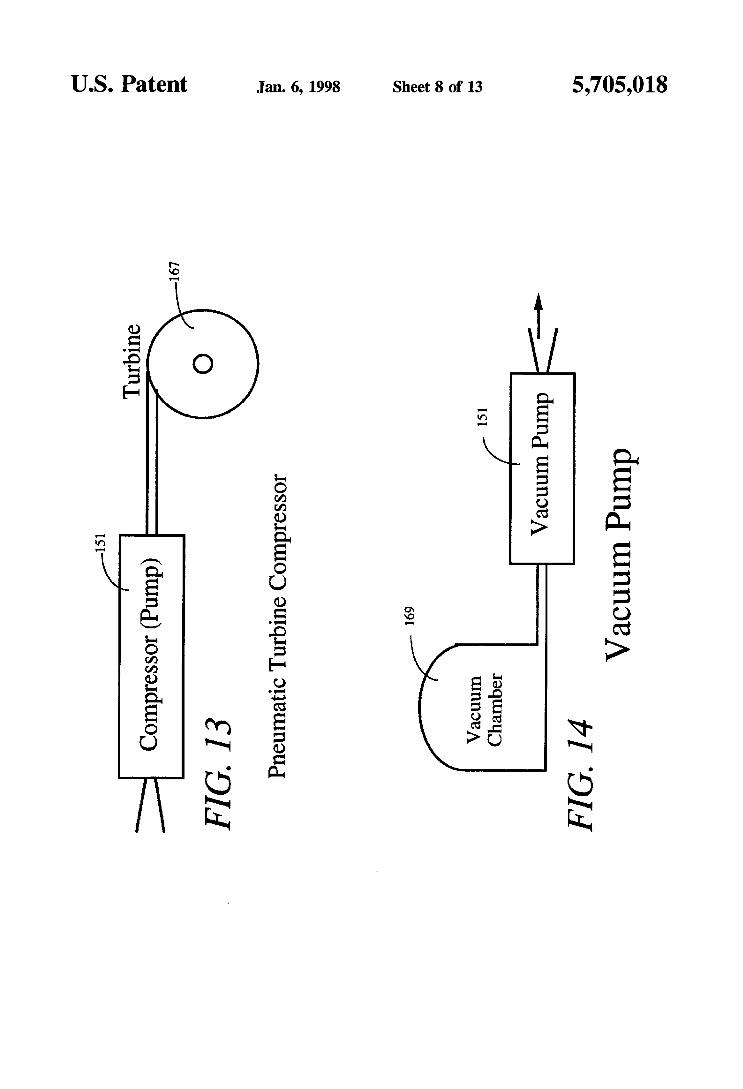
pressures the pump ~1 may function as a compressor (FIG. u). such a compressor
to pumps the membrane “valves” can isolate the cell against appreciable back pressure and for an indefinite period between successive deliveries of metered volumes of At high flow rates and
may drive a pneumatic m i n e 167 enabling a useM class of 5 Effective thermal conductivity of active heat pipes is small rotational mechanism. Examples of these meha- markedly Supfior to that of the best passive th- con-
ductive materials. A micropump 151 may be used to circu- late a fluid between a thermal source 181 and sink 183 as nisms are dental dr i l l s , miniature gyroscopes, rotating shut-
shown in FIG. 16, effectively transferring heat both within ter systems, etc. Such a compressor may also be used to m a t e small structures or via an isolation membrane or 1o the citculating medium by thermal Illifss transfer and
convective transfer. At high flow rates significant convective reagents. At hi@ membrane progression rates and high differential heat fluxes, and thus intimate thermal coupling. are achieved
pressures the device may function as a vacuum pump 151 for by the forced flow of fluids bough micrMhnnels within evacuating a chamber 169 (FIG. 14). In such applications 15 a solid surface metallization of polyurethane membranes would be transfer capacity is further enhanced by the
required to generate the greater electrostatic forces that are
plunger to dispense precise Of drugs between the medium and the and si& by waved
necessary to reduce ~ m s i ~ . Higher be absorption or &siption of latent heat generated from gas/liquid or liquid/gas phase transitions. These phase
required to overcome the high prosession rates requited (500 mlsec) to Pump
Pressures and sitions can be orchestrated by pumping where compression 2o liquefies and evacuation vaporizes. The ¬ vapor a m -
pression cycle defines such a heat engine. I n a microma- viscous gasses (vacuum pressures). actuators chined version of a closed loop sterling cycle as shown in
also be PrOgreSSiVelY increased to a staged Pressure FIG. 17, the whole engine, or a serial cascade of sterling build up along the channel. This compression bad-uP engines, may be fabricated from two fused wafers. A min- Would k PdCdarlY beneficial where gasfliquid Phase 25 iature peristaltic pump 151 draws refrigerant vapor and changes occur. compresses it into its liquid phase. The liquid, heated &om
The growing trend in biotechnology toward automation the hierated latent heat, is then cooled by convective and miniaturization of components and reagent consumption transfer into the surrounding substrate microchannel 181 and is elevating interest in miCro-fluidic~, partiCularly the need onto a h i m y thermally conductive heat exchanger 185 for physically small pumps, valves. and miXing chambers. 30 created in the substrate. Another microchannel 1238 conducts Microfabricated “labon-a-chip” instruments are emerging the cooled liquid refrigerant to an expansion nozzle 190 in for conducting electrophoresis, radiography, protein a thermally isolated cold pad 186, where the refrigerant sequencing, DNA diagnostics, and genotyping that require expands into its vapor phase, drawing the latent heat of sample and reagent delivery systems capable of regulating evaporation from the cold pad 186. This cold vapor is volumes in the 10-1000 nanoliter range. Miniature biosen- 35 conveyed in yet another microchannel 187 to the inlet port sors and drug delivery systems are other arenas requkhg 191 of the miniature peristaltic pump 151. The peristaltic microfluidic pumps, valves, pipes, and vessels. FIG. 15 pump 151 exhibits very low vibration, as it has no recipro- shows a pair of micromachined peristaltic pumps 151 cating parts. but instead has a very low mass membrane that arranged to deliver a reagent from a reservoir 171 and a rolls across the surfaces of the channels, e.g. 144, 145. A sample liquid specimen from a supply source 170 through 4o micromachined version is thus ideally suited to cooling long micro-machined delivery channel sections 172 to a reaction wavelength infrared detectors. Quipped with low porosity chamber 173. The reaction chamber 173 may output to a and low temperature membranes, micromachined peristaltic detector 174. pumped Carnot engines are capable of cooling imaging
In configurations like FIG. 15, such pumps 151 can detectors from room temperature to around 70” K. deliver and measure minuscule volumes of “incompress- 45 It is questionable whether a micromachined peristaltic ible” liquids and at precisely determined t i m e s or time pump could generate the hundreds of PSI required of the intervals, for example. by actuating the membrane at times hydrogen cycle cryogenic heat exchangers. The need for recorded in the memory of a pro&ammed digital processor tight thennal coupling between conventional cryogenic or computer. The precision with which volumes can be pumps and imaging objectives compromises the level of measured (or delivered) by the disclosed microperistaltic 50 pump vibration that an objective can endure. However, as pump is that associated with a single stepped advance of an shown in FIG. 18, a smal l peristaltic pump 151 can provide actuator strip. This minimum volume is thus defined by the the tight thermal coupling between a cryopump 201 and an product of the channel cross-section and actuator pitch. For objective (infrared detector) 203 without vibration coupling. example, a relatively large channel, by micromachining To operate at cryogenic temperatures a polymer membraned standards. with a cross-section of 0.5 mm2 and an actuator 55 peristaltic pump would be required. pitch of 0.1 mm has a minimumvolume displacement of 50 Conventional reaction wheels consist of electric motor nanoliters. By mimmachining standards, this is a @e driven fly wheels where the precession generated by fly Pump- wheel momentum changes, due to changes in angular
continuous flow microreaction cells, separate pumps velocity, provide corrective forces for stabilizing space crd. may be used for each reagent and respectively run at 60 There are no known existing methods of producing micron docking rates that are proportional to the required concen- scale motors or rotational members for incorporation in tration ratios. In batch mode operation, specific volumes of “micro” reaction wheels. A closed circUlar version 204 of a reagents may be metered by providing sufficient clock micromachined peristaltic pump may be manufactured as pulses to deliver the necessary numbex of minimum volume shown in FIG. 19, complete with convenient electrical displacements. When the pump is operated in the static or 65 interfacing, to provide an extensive range of flow rates. The intermittent mode the “across channel” membrane functions entire circular channel is lined with radially-arrayed con- as a valve. If reaction cells input ports are directly coupled ductor elements. e.g. 121, and driven by a shi f t register 208
For V a F Phase Pumps the pitch Of the
5.705,018 9 10
and cooperating oscillator/power supply 287,209. The cir- culation of a dense fluid in a smooth contoured isotropically etched circular channel of the pump 204 mimics the function of a reaction wheel. Precession forces now result from changes in fluid flow rates within the channel or channels.
The large electrostatic forces generated on a membrane across a thin layer of insulation has other applications aside from a peristaltic pump. If the membrane cross-section is small, then significant pressures are required to separate the membrane from or prevent the membrane attaching to the 10
withhold pressures and reduce propensity toward valve leakage. With 100 volts across insulation between the mem- bane and conductive strip actuators and a small membrane cross-section, a "normally open" valve, FIGS. 20 and 21, 15
over said channel; and realized. The closing pressure limit is determined by the effective area of the membrane and the electrostatic force means for attracting said membrane into said channel so
as to contact a region of said channel and for causing generated across the thin insulation layer. The valve ports 211.213 may be at either end of a pump-like channel 215, 20 the region of contact bemeen channel and said perpendicular to a channel and perforating a conductive strip membrane to move down said channel so as to create or one perpendicular and one parallel. Because the valve a pumping action. actuator is electrostatic and draws no current, little power, 10. The pump structure of claim 9 wherein said channel aside from Potential, is required to b e P the further includes an inlet end and an output end, said inlet end valve closed. 25 being arranged to receive an ambient gas atmosphere and
To summarize, some of the advantages and areas of said outlet end being connected to supply ambient gas application of the invention are as follows: pumped from said atmosphere to a means for analyzing the
1. The miniature peristaltic pump can be used to transport Chemical &UP Of Said gas ~ 0 S P h e ~ - fluids (or vapors) over an extensive range of flow rates. 11. The pump structure of claim 10 wherein said means
2. The suggested implementation of the pump doubles as 30 f o \ ~ $ ~ ~ ~ ~ ~ & ~ ~ c ~ 9 wherein said substrate
comprises a heated thermally conductive material and fur- a positive displacement flow meter, thus the mass flow
3- Microstructured pump-channe1 implementation On a circulation through said channel so as to effect convective substrate, complete with drive electronics. results in a coupling to the substrate, thereby enabling of the
substrate. microreaction wheel. 4. Many of these channels may be organized in concentric 13. The pump structure of claim 9 further including a
circles and some of them operated in opposite direc- pneumatic turbine having a driving port connected to an tions to maximize momentum change. output end of said channel and wherein said means for
5. The electrostatic actuator mechanism requires potential amacting further functions to P W air through said channel but no current thus it requires little power and therefore so as to drive said Pneumatic turbine.
has an inlet end connected to an output port of a vacuum constraints. no noise and no moving parts. chamber and wherein said means for attracting furtha
possible for maximum angular momen- In a fulfy 45 15. The structure of claim 9 further including means for connecting an inlet end of said channel to receive a liquid
substrate would be chemical input from a liquid chemical supply and means for connecting an outlet of said channel to a reaction chamber devices.
Those in the art will that various means, whereby said pump structure functions to transport
further including a second a second
3. The pump structure of claim 1 wherein said substrate comprises a semiconductor substrate.
4. The pump structure of claim 2 wherein said membrane comprises a graphite impregnated polyurethane membrane.
5. The pump structure of claim 2 wherein said membrane COmpfiSeS a polyurethane membrane metallization applied to at least one surface thereof.
6. The pump structure of claim 1 wherein said membrane has an
7. The pump s t r u m of claim 1 further including
succession so as to create a peristaltic pumping action.
comprises a flexible
Of 305b*
channel surface. Multiple strip c o n ~ c t o ~ increase for d y i n g a to each Of said in
8. The pump structure of claim wherein said membrane
9. The micro-ature pump structure comprising: a substrate having a channel formed therein;
strumem
capable Of hundreds Of Pressure be a flexible conductive me&ane affixed on said subs&&
rate and angular momentum can be including -s for supplying a cooling fluid for
35
generates v h d y no heat. There are no orientation 14. The Pump SmctUre of claim 9 wherein said channel
The pump-channe1 need be Of the largest diameter functions so as to evacuate said vacuum
Tam craft the inner area Of the for electronics Or Other
ada@&iOnS and modific&.iOllS Of the just-described preferred H) said to ebb. embodiment can be configured without departing from the scope and spirit of the invention. Therefore. it is to be 16. The of claim
pump structure comprising a second understood that, within the scope Of the the invention
claims* be pacticed Other than as specificauY
flexible m a n e , a second channel, and a second means for amacting said membrane into said second channel so as
55 to contact a region of said second channel and for causing the region of contact between said second channel and said membrane to move down said second channel so as to allocate a second chemical to said reaction chamber.
described herein. What is claimed is: 1. A miniature pump structure comprising: a substrate having a channel therein; a series of conductive strips separated by insulative bar- 17. The pump structure of claim 9 further including a
rim formed in Said channel, Said Strips and barriers 60 t h d sourw and a t h d si& and wherein said channel lying transverse to said channel;
nel; and
and between said strips and said membrane.
first and second sidewalls and a rounded boaom.
is disposed such that said means for attracting circulates a fluid between an output of said thermal source and an input of said thermal sink.
18. The pump s t ~ c t u r e of claim 9 wherein said channel 65 is connected to a source of refrigerant vapor and said means
for attracting further operates to compress said vapor into its liquid phase.
a flexible conductive membrane located over said chan-
an insulative layer positioned over said conductive strips
2. The pump structure of claim 1 wherein said channel has

5,705,018 11 12
19. The pump structure of claim 18 and fuither included
20. The pump structure of claim 9 including means for
a second array of conductive actuator elements located on said second substrate, each element traversing said second channel;
respective first and second insulation layers formed over
in a means for creating a closed loop sterling cycle.
adapting Said Pump structure to FOVide tight *ermal piing a cryogenic p q and an Objective. said first and second m y s of actuator elements;
as to create a fluidic reaction wheel. 22. The pump structure of claim 9 and wherein said means
for attracting is operated so as to selectively close and open 10 a fluid path between an inlet to said channel and an output created in said substrate. 23. The pump structure of claim 9 wherein said means for
amacting further generates a measure Of flow rate through said channel.
21. The pump structure of claim 9 wherein said channel is &ah and said means for amacting M e r opgates so a flexible d e c ~ c a u Y condu&h'e me&ane; and
means for connecting said substrates together such that the first and second channels lie opposite one another with said membrane sandwiched between said first and second insulation layers.
25. The pump of claim 24 wherein said means for
first and second bond metal trenches lying parallel, respectively, to said first and second channels; and
bond metal means in said first and second trenches for forming a hermetic seal between an insulation layer and a subslrate surface.
26. The pump of ~1- 25 firrtha including a respective 2o conductor channel means in each substrate for establishing
connecting comprises;
15 24. A miniature pump comprising: first and second substrates, having respective first and
second channels formed therein and positioned to lie opposite one another when said first and second sub- strates are positioned adjacent one another;
a first array of conductive actuator elements located on said first substrate, each element traversing said first channel: * * * * *
electrical connection to said membrane.